Surgical fastener applying apparatus, kits and methods for endoscopic procedures
Zhang , et al.
U.S. patent number 10,335,146 [Application Number 15/129,143] was granted by the patent office on 2019-07-02 for surgical fastener applying apparatus, kits and methods for endoscopic procedures. This patent grant is currently assigned to Coviden LP. The grantee listed for this patent is Covidien LP. Invention is credited to Shunhong Xu, Jiangfeng Zhang, Xiliang Zhang.


View All Diagrams
| United States Patent | 10,335,146 |
| Zhang , et al. | July 2, 2019 |
Surgical fastener applying apparatus, kits and methods for endoscopic procedures
Abstract
An endoscopic surgical device is provided and includes a handle assembly including a handle housing and a trigger operatively connected to the handle housing, and a drive mechanism actuatable by the trigger; and an endoscopic assembly selectively connectable to the handle assembly. The endoscopic assembly includes an outer tube defining a lumen therethrough and having a helical thread disposed within the lumen thereof; an inner tube rotatably supported in the outer tube and being operatively connectable to the drive mechanism, the inner tube defining a splined distal end, wherein the splined distal end of the inner tube is defined by a pair of opposed longitudinally extending tines and a pair of opposed longitudinally extending channels; and a plurality of surgical anchors loaded in the splined distal end of the inner tube.
| Inventors: | Zhang; Jiangfeng (Shanghai, CN), Xu; Shunhong (Shanghai, CN), Zhang; Xiliang (Shanghai, CN) | ||||||||||
|---|---|---|---|---|---|---|---|---|---|---|---|
| Applicant: |
|
||||||||||
| Assignee: | Coviden LP (Mansfield,
MA) |
||||||||||
| Family ID: | 54239276 | ||||||||||
| Appl. No.: | 15/129,143 | ||||||||||
| Filed: | April 2, 2014 | ||||||||||
| PCT Filed: | April 02, 2014 | ||||||||||
| PCT No.: | PCT/CN2014/074583 | ||||||||||
| 371(c)(1),(2),(4) Date: | September 26, 2016 | ||||||||||
| PCT Pub. No.: | WO2015/149292 | ||||||||||
| PCT Pub. Date: | October 08, 2015 |
Prior Publication Data
| Document Identifier | Publication Date | |
|---|---|---|
| US 20170128068 A1 | May 11, 2017 | |
| Current U.S. Class: | 1/1 |
| Current CPC Class: | A61B 17/064 (20130101); A61B 17/00234 (20130101); A61B 17/07207 (20130101); A61F 2/0063 (20130101); A61B 17/068 (20130101); A61B 2017/00407 (20130101); A61B 2017/0046 (20130101); A61B 2017/00477 (20130101); A61B 2017/0648 (20130101); A61B 2017/2946 (20130101); A61B 2017/2903 (20130101); A61B 2017/2923 (20130101); A61F 2002/0072 (20130101) |
| Current International Class: | A61F 2/00 (20060101); A61B 17/064 (20060101); A61B 17/068 (20060101); A61B 17/072 (20060101); A61B 17/29 (20060101); A61B 17/00 (20060101) |
References Cited [Referenced By]
U.S. Patent Documents
| 3596528 | August 1971 | Dittrich et al. |
| 3866510 | February 1975 | Eibes et al. |
| 4350491 | September 1982 | Steuer |
| 4884572 | December 1989 | Bays et al. |
| 5085661 | February 1992 | Moss |
| 5171247 | December 1992 | Hughett et al. |
| 5171249 | December 1992 | Stefanchik et al. |
| 5176306 | January 1993 | Heimerl et al. |
| 5207697 | May 1993 | Carusillo |
| 5228256 | July 1993 | Dreveny |
| 5236563 | August 1993 | Loh |
| 5246441 | September 1993 | Ross et al. |
| 5246450 | September 1993 | Thornton et al. |
| 5312023 | May 1994 | Green et al. |
| 5330487 | July 1994 | Thornton et al. |
| 5344061 | September 1994 | Crainich |
| 5356064 | October 1994 | Green et al. |
| 5382254 | January 1995 | McGarry et al. |
| 5398861 | March 1995 | Green |
| 5403327 | April 1995 | Thornton et al. |
| 5433721 | July 1995 | Hooven et al. |
| 5439468 | August 1995 | Schulze et al. |
| 5466243 | November 1995 | Schmieding et al. |
| 5467911 | November 1995 | Tsuruta et al. |
| 5474566 | December 1995 | Alesi et al. |
| 5474567 | December 1995 | Stefanchik et al. |
| 5522844 | June 1996 | Johnson |
| 5527319 | June 1996 | Green et al. |
| 5553765 | September 1996 | Knodel et al. |
| 5562685 | October 1996 | Mollenauer et al. |
| 5564615 | October 1996 | Bishop et al. |
| 5582615 | December 1996 | Foshee et al. |
| 5582616 | December 1996 | Bolduc et al. |
| 5584425 | December 1996 | Savage et al. |
| 5588581 | December 1996 | Conlon et al. |
| 5601571 | February 1997 | Moss |
| 5601573 | February 1997 | Fogelberg et al. |
| 5626613 | May 1997 | Schmieding |
| 5628752 | May 1997 | Asnis et al. |
| 5649931 | July 1997 | Bryant et al. |
| 5662662 | September 1997 | Bishop et al. |
| 5681330 | October 1997 | Hughett et al. |
| 5683401 | November 1997 | Schmieding et al. |
| 5685474 | November 1997 | Seeber |
| 5697935 | December 1997 | Moran et al. |
| 5709692 | January 1998 | Mollenauer et al. |
| 5730744 | March 1998 | Justin et al. |
| 5732806 | March 1998 | Foshee et al. |
| 5735854 | April 1998 | Caron |
| 5741268 | April 1998 | Schutz |
| 5762255 | June 1998 | Chrisman et al. |
| 5782844 | July 1998 | Yoon et al. |
| 5810882 | September 1998 | Bolduc et al. |
| 5811552 | September 1998 | Nishikata et al. |
| 5824008 | October 1998 | Bolduc et al. |
| 5830221 | November 1998 | Stein et al. |
| 5843087 | December 1998 | Jensen et al. |
| 5897564 | April 1999 | Schulze et al. |
| 5904693 | May 1999 | Dicesare |
| 5910105 | June 1999 | Swain et al. |
| 5911722 | June 1999 | Adler et al. |
| 5928244 | July 1999 | Tovey |
| 5928252 | July 1999 | Steadman et al. |
| 5931844 | August 1999 | Thompson et al. |
| 5941439 | August 1999 | Kammerer et al. |
| 5954259 | September 1999 | Viola |
| 5961524 | October 1999 | Crombie |
| 5964772 | October 1999 | Bolduc et al. |
| 5976160 | November 1999 | Crainich |
| 5997552 | December 1999 | Person et al. |
| 6010513 | January 2000 | Tormala et al. |
| 6013991 | January 2000 | Philipp |
| 6039753 | March 2000 | Meislin |
| 6074395 | June 2000 | Trott et al. |
| 6099537 | August 2000 | Sugai |
| 6126670 | October 2000 | Walker et al. |
| 6132435 | October 2000 | Young |
| 6146387 | November 2000 | Trott et al. |
| 6183479 | February 2001 | Tormala et al. |
| 6228098 | May 2001 | Kayan et al. |
| 6235058 | May 2001 | Huene |
| 6241736 | June 2001 | Sater et al. |
| 6261302 | July 2001 | Voegele et al. |
| 6296656 | October 2001 | Bolduc et al. |
| 6330964 | December 2001 | Kayan et al. |
| 6387113 | May 2002 | Hawkins et al. |
| 6402757 | June 2002 | Moore, III et al. |
| 6425900 | July 2002 | Knodel et al. |
| 6439446 | August 2002 | Perry et al. |
| 6440136 | August 2002 | Gambale et al. |
| 6450391 | September 2002 | Kayan et al. |
| 6457625 | October 2002 | Tormala et al. |
| 6551333 | April 2003 | Kuhns et al. |
| 6562051 | May 2003 | Bolduc et al. |
| 6572626 | June 2003 | Knodel et al. |
| 6589249 | July 2003 | Sater et al. |
| 6592593 | July 2003 | Parodi et al. |
| 6626916 | September 2003 | Yeung et al. |
| 6632228 | October 2003 | Fortier et al. |
| 6652538 | November 2003 | Kayan et al. |
| 6663656 | December 2003 | Schmieding et al. |
| 6666854 | December 2003 | Lange |
| 6695867 | February 2004 | Ginn et al. |
| 6733506 | May 2004 | McDevitt et al. |
| 6743240 | June 2004 | Smith et al. |
| 6749621 | June 2004 | Pantages et al. |
| 6755836 | June 2004 | Lewis |
| 6773438 | August 2004 | Knodel et al. |
| 6800081 | October 2004 | Parodi |
| 6824548 | November 2004 | Smith et al. |
| 6837893 | January 2005 | Miller |
| 6840943 | January 2005 | Kennefick et al. |
| 6843794 | January 2005 | Sixto, Jr. et al. |
| 6869435 | March 2005 | Blake, III |
| 6884248 | April 2005 | Bolduc et al. |
| 6887244 | May 2005 | Walker et al. |
| 6893446 | May 2005 | Sater et al. |
| 6905057 | June 2005 | Swayze et al. |
| 6929661 | August 2005 | Bolduc et al. |
| 6942674 | September 2005 | Belef et al. |
| 6945979 | September 2005 | Kortenbach et al. |
| 6960217 | November 2005 | Bolduc |
| 6966919 | November 2005 | Sixto, Jr. et al. |
| 6988650 | January 2006 | Schwemberger et al. |
| 7000819 | February 2006 | Swayze et al. |
| 7128754 | October 2006 | Bolduc |
| 7147657 | December 2006 | Chiang et al. |
| 7204847 | April 2007 | Gambale |
| 7261716 | August 2007 | Strobel et al. |
| 7491232 | February 2009 | Bolduc et al. |
| 7544198 | June 2009 | Parodi |
| 7591842 | September 2009 | Parodi |
| 7637932 | December 2009 | Bolduc et al. |
| 7670362 | March 2010 | Zergiebel |
| 7758612 | July 2010 | Shipp |
| 7823267 | November 2010 | Bolduc |
| 7828838 | November 2010 | Bolduc et al. |
| 7862573 | January 2011 | Darois et al. |
| 7867252 | January 2011 | Criscuolo et al. |
| 7905890 | March 2011 | Whitfield et al. |
| 7931660 | April 2011 | Aranyi et al. |
| 7959663 | June 2011 | Bolduc |
| 7959670 | June 2011 | Bolduc |
| 8002811 | August 2011 | Corradi et al. |
| 8034076 | October 2011 | Criscuolo et al. |
| 8075570 | December 2011 | Bolduc et al. |
| 8083752 | December 2011 | Bolduc |
| 8087142 | January 2012 | Levin et al. |
| 8092519 | January 2012 | Bolduc |
| 8114099 | February 2012 | Shipp |
| 8114101 | February 2012 | Criscuolo et al. |
| 8216272 | July 2012 | Shipp |
| 8231639 | July 2012 | Bolduc et al. |
| 8282670 | October 2012 | Shipp |
| 8292933 | October 2012 | Zergiebel |
| 8323314 | December 2012 | Blier |
| 8328823 | December 2012 | Aranyi et al. |
| 8343176 | January 2013 | Criscuolo et al. |
| 8343184 | January 2013 | Blier |
| 8382778 | February 2013 | Criscuolo et al. |
| 8414627 | April 2013 | Corradi et al. |
| 8465520 | June 2013 | Blier |
| 8474679 | July 2013 | Felix |
| 8506475 | August 2013 | Brannon |
| 8579919 | November 2013 | Bolduc et al. |
| 8579920 | November 2013 | Nering et al. |
| 8597311 | December 2013 | Criscuolo et al. |
| 8685044 | April 2014 | Bolduc et al. |
| 8690897 | April 2014 | Bolduc |
| 8728102 | May 2014 | Criscuolo et al. |
| 8728120 | May 2014 | Blier |
| 8777969 | July 2014 | Kayan |
| 8821514 | September 2014 | Aranyi |
| 8821522 | September 2014 | Criscuolo et al. |
| 8821557 | September 2014 | Corradi et al. |
| 8852215 | October 2014 | Criscuolo et al. |
| 8875971 | November 2014 | Hall |
| 8920439 | December 2014 | Cardinale et al. |
| 8926637 | January 2015 | Zergiebel |
| 9017345 | April 2015 | Taylor |
| 9023065 | May 2015 | Bolduc et al. |
| 9028495 | May 2015 | Mueller et al. |
| 9138225 | September 2015 | Huang |
| 9186138 | November 2015 | Corradi et al. |
| 9259221 | February 2016 | Zergiebel |
| 9282961 | March 2016 | Whitman et al. |
| 9332983 | May 2016 | Shipp |
| 9351728 | May 2016 | Sniffin |
| 9351733 | May 2016 | Fischvogt |
| 9358004 | June 2016 | Sniffin |
| 9358010 | June 2016 | Wenchell |
| 9364274 | June 2016 | Zergiebel |
| 9402623 | August 2016 | Kayan |
| 9486218 | November 2016 | Criscuolo et al. |
| 9526498 | December 2016 | Reed |
| 9655621 | May 2017 | Abuzaina |
| 9668730 | June 2017 | Sniffin |
| 9801633 | October 2017 | Sholev et al. |
| 9867620 | January 2018 | Fischvogt et al. |
| 9987010 | June 2018 | Zergiebel |
| 10070860 | September 2018 | Zergiebel |
| 2002/0087170 | July 2002 | Kuhns |
| 2003/0009441 | January 2003 | Holsten |
| 2003/0114839 | June 2003 | Looper et al. |
| 2004/0092937 | May 2004 | Criscuolo et al. |
| 2004/0111089 | June 2004 | Stevens et al. |
| 2004/0127916 | July 2004 | Bolduc et al. |
| 2004/0181222 | September 2004 | Culbert et al. |
| 2004/0193217 | September 2004 | Lubbers et al. |
| 2004/0243139 | December 2004 | Lewis |
| 2006/0129152 | June 2006 | Shipp |
| 2006/0129154 | June 2006 | Shipp |
| 2007/0038220 | February 2007 | Shipp |
| 2007/0088390 | April 2007 | Paz et al. |
| 2007/0162030 | July 2007 | Aranyi et al. |
| 2008/0086154 | April 2008 | Taylor |
| 2008/0097523 | April 2008 | Bolduc et al. |
| 2008/0147113 | June 2008 | Nobis et al. |
| 2008/0188868 | August 2008 | Weitzner et al. |
| 2008/0243106 | October 2008 | Coe et al. |
| 2008/0281336 | November 2008 | Zergiebel |
| 2008/0281353 | November 2008 | Aranyi |
| 2008/0312687 | December 2008 | Blier |
| 2009/0112234 | April 2009 | Crainich et al. |
| 2009/0118776 | May 2009 | Kelsch et al. |
| 2009/0188965 | July 2009 | Levin et al. |
| 2010/0030262 | February 2010 | McLean |
| 2010/0270354 | October 2010 | Rimer et al. |
| 2010/0292710 | November 2010 | Daniel et al. |
| 2010/0292713 | November 2010 | Cohn |
| 2010/0292715 | November 2010 | Nering et al. |
| 2011/0022065 | January 2011 | Shipp |
| 2011/0042441 | February 2011 | Shelton, IV et al. |
| 2011/0060349 | March 2011 | Cheng et al. |
| 2011/0071578 | March 2011 | Colesanti et al. |
| 2011/0079627 | April 2011 | Cardinale et al. |
| 2011/0087240 | April 2011 | Shipp |
| 2011/0295269 | December 2011 | Swensgard et al. |
| 2011/0295282 | December 2011 | Glick et al. |
| 2012/0059397 | March 2012 | Criscuolo et al. |
| 2012/0109157 | May 2012 | Criscuolo et al. |
| 2013/0110088 | May 2013 | Wenchell |
| 2013/0197591 | August 2013 | Corradi et al. |
| 2014/0114329 | April 2014 | Zergiebel |
| 2014/0200587 | July 2014 | Pompee et al. |
| 2014/0243855 | August 2014 | Sholev et al. |
| 2014/0276967 | September 2014 | Fischvogt et al. |
| 2014/0276969 | September 2014 | Wenchell et al. |
| 2014/0276972 | September 2014 | Abuzaina et al. |
| 2014/0316446 | October 2014 | Kayan |
| 2015/0001272 | January 2015 | Sniffin et al. |
| 2015/0005748 | January 2015 | Sniffin et al. |
| 2015/0005788 | January 2015 | Sniffin |
| 2015/0005789 | January 2015 | Sniffin |
| 2015/0018847 | January 2015 | Criscuolo et al. |
| 2015/0032130 | January 2015 | Russo |
| 2015/0080911 | March 2015 | Reed |
| 2015/0133970 | May 2015 | Ranucci et al. |
| 2015/0133971 | May 2015 | Ranucci et al. |
| 2015/0133972 | May 2015 | Ranucci et al. |
| 2015/0150558 | June 2015 | Zergiebel |
| 2015/0327859 | November 2015 | Bolduc |
| 2016/0007991 | January 2016 | Bolduc |
| 2016/0007996 | January 2016 | Bolduc |
| 2016/0066971 | March 2016 | Corradi et al. |
| 2016/0074034 | March 2016 | Shipp |
| 2016/0135807 | May 2016 | Zergiebel |
| 2016/0166255 | June 2016 | Fischvogt |
| 2016/0249912 | September 2016 | Fischvogt |
| 2016/0270778 | September 2016 | Zergiebel |
| 2016/0270835 | September 2016 | Reed |
| 2016/0278766 | September 2016 | Wenchell et al. |
| 2016/0338694 | November 2016 | Kayan |
| 2016/0345967 | December 2016 | Sniffin et al. |
| 2017/0181789 | June 2017 | Ding |
| 2017/0231631 | August 2017 | Abuzaina et al. |
| 2017/0265859 | September 2017 | Sniffin |
| 2017/0333092 | November 2017 | McGahan |
| 2018/0042591 | February 2018 | Russo et al. |
| 2018/0116670 | May 2018 | Fischvogt et al. |
| 2018/0242977 | August 2018 | Tan |
| 2999907 | May 2017 | CA | |||
| 3009420 | Jul 2017 | CA | |||
| 201438958 | Apr 2010 | CN | |||
| 102413863 | Apr 2012 | CN | |||
| 101933795 | Sep 2012 | CN | |||
| 10300787 | Sep 2004 | DE | |||
| 10 2010 015009 | Oct 2011 | DE | |||
| 0374088 | Jun 1990 | EP | |||
| 0834280 | Apr 1998 | EP | |||
| 1273272 | Jan 2003 | EP | |||
| 1908409 | Apr 2008 | EP | |||
| 1990013 | Nov 2008 | EP | |||
| 2 055 241 | May 2009 | EP | |||
| 1908409 | Dec 2010 | EP | |||
| 2399538 | Dec 2011 | EP | |||
| 2484294 | Aug 2012 | EP | |||
| 09149906 | Jun 1997 | JP | |||
| 00/16701 | Mar 2000 | WO | |||
| 2002/034140 | May 2002 | WO | |||
| 2003/034925 | May 2003 | WO | |||
| 2003/103507 | Dec 2003 | WO | |||
| 2004/112841 | Dec 2004 | WO | |||
| 2005004727 | Jan 2005 | WO | |||
| WO-2008130826 | Oct 2008 | WO | |||
| 2009/039506 | Mar 2009 | WO | |||
| WO-2010135325 | Nov 2010 | WO | |||
| 2012/064692 | May 2012 | WO | |||
| 2013/046115 | Apr 2013 | WO | |||
| WO-2015149292 | Oct 2015 | WO | |||
| WO-2016000245 | Jan 2016 | WO | |||
| WO-2016000246 | Jan 2016 | WO | |||
| WO-2016000255 | Jan 2016 | WO | |||
| WO-2016011594 | Jan 2016 | WO | |||
Other References
|
European Office Action corresponding to Patent Application EP 14 15 89465 dated Apr. 26, 2018. cited by applicant . Japanese Office Action corresponding to Patent Application JP 2014-132105 dated May 1, 2018. cited by applicant . Japanese Office Action corresponding to Patent Application JP 2014-047708 dated May 14, 2018. cited by applicant . Chinese Second Office Action corresponding to Patent Application CN 2014103559671 dated May 25, 2018. cited by applicant . Australian Examination Report No. 1 corresponding to Patent Application AU 2014302551 dated Jul. 16, 2018. cited by applicant . Japanese Office Action corresponding to Patent Application JP 2014-047708 dated Aug. 15, 2018. cited by applicant . Chinese Second Office Action corresponding to counterpart Chinese Appln. No. 201480077682.4 dated Mar. 21, 2018. cited by applicant . International Search Report for (PCT/CN2014/074583) date of completion is Dec. 4, 2014 (3 pages). cited by applicant . Extended European Search Report corresponding to counterpart application EP 10 01 2659.8, completed Dec. 21, 2010 and dated Jan. 3, 2011; 3 pages. cited by applicant . Extended European Search Report corresponding to counterpart application EP 10 01 26465, completed Feb. 11, 2011 and dated Feb. 22, 2011; 10 pages. cited by applicant . Extended European Search Report corresponding to counterpart application EP 11 25 0549.0, completed Sep. 9, 2013 and dated Sep. 17, 2013; 9 pages. cited by applicant . Extended European Search Report corresponding to counterpart application EP 14 15 9394.7, completed Apr. 16, 2014 and dated Apr. 29, 2014; 8 pages. cited by applicant . Extended European Search Report corresponding to counterpart application EP 14 15 89465, completed Jun. 20, 2014 and dated Jul. 8, 2014; (9 pp). cited by applicant . Extended European Search Report corresponding to counterpart application EP 14 17 8107.0, completed Nov. 24, 2014 and dated Dec. 3, 2014; (5 pp). cited by applicant . Extended European Search Report corresponding to counterpart application EP 14 17 4656.0, completed Jan. 16, 2015 and dated Jan. 26, 2015; (7 pp). cited by applicant . Extended European Search Report corresponding to counterpart application EP 14 18 49075, completed Jan. 12, 2015 and dated Jan. 27, 2015; (9 pp). cited by applicant . Extended European Search Report corresponding to counterpart Int'l Application No. EP 14 18 1900.3 dated Apr. 9, 2015. cited by applicant . Extended European Search Report corresponding to counterpart Int'l, Application No. EP 14 19 7885.8 dated Mar. 30, 2015. cited by applicant . Chinese First Office Action corresponding to Chinese Patent Appln. No. 201480037169.2 dated Jun. 29, 2017. cited by applicant . Chinese First Office Action corresponding to Chinese Patent Appln. No. 201410418879.1 dated Jun. 29, 2017. cited by applicant . European Office Action corresponding to European Patent Appln. No. 14 17 8107.0 dated Oct. 12, 2017. cited by applicant . Australian Examination Report No. 1 corresponding to Australian Patent Appln. No. 2014200870 dated Oct. 26, 2017. cited by applicant . Chinese Second Office Action corresponding to Chinese Patent Appln. No. 201410090675 dated Nov. 6, 2017. cited by applicant . Japanese Office Action corresponding to Japanese Patent Appln. No. 2014-048652 dated Nov. 14, 2017. cited by applicant . Japanese Office Action corresponding to Japanese Patent Appln. No. 2014-047708 dated Nov. 14, 2017. cited by applicant . Chinese Second Office Action corresponding to Chinese Patent Appln. No. 2014103063407 dated Feb. 1, 2018. cited by applicant . Australian Examination Report No. 1 corresponding to Australian Patent Appln. No. 2014202970 dated Mar. 9, 2018. cited by applicant . Japanese Office Action corresponding to Japanese Patent Appln. No. 2014-048652 dated Mar. 15, 2018. cited by applicant . Chinese Second Office Action corresponding to Chinese Patent Appln. No. 2014800776824 dated Mar. 21, 2018. cited by applicant . Australian Examination Report No. 1 corresponding to Australian Patent Appln. No. 2014202972 dated Mar. 27, 2018. cited by applicant . Extended European Search Report corresponding to Int'l, Application No. EP 14 15 1663.3 dated Jun. 7, 2016. cited by applicant. |
Primary Examiner: Desai; Hemant
Assistant Examiner: Martin; Veronica
Claims
What is claimed is:
1. An endoscopic surgical device, comprising; a handle assembly including a handle housing and a trigger operatively connected to the handle housing, and a drive mechanism actuatable by the trigger, wherein the handle housing includes a tooth projecting from a surface thereof, wherein the handle assembly includes a ferrule removably and rotatably connected to the handle housing, the ferrule defining an aperture therein that is in operative alignment with the drive mechanism of the handle assembly, the ferrule including a tooth projecting radially into the aperture of the ferrule, the ferrule having: a first position wherein the tooth of the ferrule is radially aligned with the tooth of the handle housing; and a second position wherein the tooth of the ferrule is radially out of alignment with the tooth of the handle housing; and an endoscopic assembly selectively connectable to the handle assembly, the endoscopic assembly including: an outer tube defining a lumen therethrough and having an outer helical thread disposed within the lumen thereof, the outer tube defining a proximal end and a distal end; an inner tube rotatably supported in the outer tube, the inner tube defining a lumen therethrough and having a proximal end and a splined distal end, wherein the splined distal end of the inner tube is defined by a pair of opposed longitudinally extending tines and a pair of opposed longitudinally extending channels; a plurality of surgical anchors loaded in the lumen of the inner tube of the endoscopic assembly, wherein each anchor of the plurality of surgical anchors includes a threaded body portion, and a head portion defining a pair of opposed radially outer threads and a pair of opposed radial recesses, wherein the pair of radial recesses of each head portion receives a respective tine of the pair of opposed longitudinally extending channel of the inner tube and wherein the pair of opposed radially outer threads of each head portion projects from the pair of opposed longitudinally extending channels of the inner tube and engage the inner helical thread of the outer tube; and a connector having: an outer connector member non-rotatably connected to the proximal end of the outer tube and being non-rotatably connectable to the handle assembly, the outer connector member including a channel formed therein, wherein: the channel of the outer connector member receives the tooth of the handle housing when the endoscopic assembly is connected to the handle assembly; and the tooth inhibits rotation of the outer connector member when the trigger is actuated to rotate the inner connector member of the endoscopic assembly; and an inner connector member non-rotatably connected to the proximal end of the inner tube and being non-rotatably connectable to the drive mechanism, wherein the outer connector member and the inner connector member are rotatable with respect to one another.
2. The endoscopic surgical device according to claim 1, wherein when the ferrule is in the second position the endoscopic assembly is connectable to and disconnectable from the handle assembly.
3. The endoscopic surgical device according to claim 2, wherein the channel of the outer connector member is formed in an outer radial surface thereof and extends axially along an entire length thereof, and wherein during connection of the endoscopic assembly to the handle assembly and disconnection of the endoscopic assembly from the handle assembly, the tooth of the ferrule passes along the channel of the outer connector member.
4. The endoscopic surgical device according to claim 3, wherein the outer channel of the outer connector member defines a length, wherein when the endoscopic assembly is connected to the handle assembly, the tooth of the ferrule is disposed outside of the channel of the outer connector member, and wherein the ferrule is rotatable to the first position such that the tooth of the ferrule inhibits disconnection of the endoscopic assembly and handle assembly from one another.
5. The endoscopic surgical device according to claim 1, wherein the ferrule is rotatable to a third position wherein the ferrule is disconnectable from the handle housing.
6. The endoscopic surgical device according to claim 1, wherein the handle assembly includes a safety lock assembly supported on the handle housing, the safety lock assembly includes a proximal end disposed within the handle housing and being in operative association with the drive mechanism, and a distal end projecting from the handle housing and being in operative association with the ferrule.
7. The endoscopic surgical device according to claim 6, wherein: when the ferrule is in the first position, the safety lock assembly is in a first position such that the proximal end of the safety lock assembly engages the drive mechanism to block operation of the drive mechanism; and when the ferrule is in the second position, the safety lock assembly is in a second position such that the proximal end of the safety lock assembly is disengaged from the drive mechanism to permit operation of the drive mechanism.
8. The endoscopic surgical device according to claim 7, wherein the ferrule is dimensioned to actuate the safety lock assembly between the first and second positions thereof as the ferrule is moved between respective first and second positions thereof.
9. The endoscopic surgical device according to claim 7, wherein the safety lock assembly includes a lock plate supported on and extending radially from the proximal end thereof, wherein the drive mechanism includes a gear defining a slot therein, and wherein the lock plate of the safety lock assembly is disposed within the slot of the gear of the drive mechanism when the ferrule is in the first position.
10. The endoscopic surgical device according to claim 9, wherein the drive mechanism includes a plurality of gears, wherein at least one gear is actuated by the trigger, and wherein at least one gear actuates a drive shaft extending from the handle housing, wherein the drive shaft is keyed for selective connection to the inner connector member supported at the proximal end of the inner tube.
Description
CROSS-REFERENCE TO RELATED APPLICATIONS
This application is a U.S. National Stage Application filed under 35 U.S.C. .sctn. 371(a), which claims priority and benefit of International Patent Application Serial No. PCT/CN2014/074583, filed Apr. 2, 2014, the entire disclosure of which is incorporated by reference herein.
BACKGROUND
1. Technical Field
The present disclosure relates to a surgical apparatus, device and/or system for performing endoscopic surgical procedures and methods of use thereof. More specifically, the present disclosure relates to a surgical fastener applying apparatus, device and/or system for performing endoscopic surgical procedures, which is loadable with disposable endoscopic loading units containing absorbable or permanent surgical fasteners, to kits, and methods of use thereof.
2. Background of Related Art
Various surgical procedures require instruments capable of applying fasteners to tissue to form tissue connections or to secure objects to tissue. For example, during hernia repair it is often desirable to fasten a mesh to body tissue. In certain hernias, such as direct or indirect inguinal hernias, a part of the intestine protrudes through a defect in the abdominal wall to form a hernial sac. The defect may be repaired using an open surgery procedure in which a relatively large incision is made and the hernia is closed outside the abdominal wall by suturing. The mesh is attached with sutures over the opening in the abdominal wall to provide reinforcement.
Minimally invasive, e.g., endoscopic or laparoscopic, surgical procedures are currently available to repair a hernia. In laparoscopic procedures, surgery is performed in the abdomen through a small incision while in endoscopic procedures, surgery is performed through narrow endoscopic tubes or cannulas inserted through small incisions in the body. Laparoscopic and endoscopic procedures generally utilize long and narrow instruments capable of reaching remote regions within the body and configured to seal with the incision or tube they are inserted through. Additionally, the instruments must be capable of being actuated remotely, that is, from outside the body.
Currently, minimally invasive surgical techniques for hernia repair utilize surgical fasteners, e.g., surgical tacks, staples, and clips, to secure the mesh to the tissue to provide reinforcement and structure for encouraging tissue ingrowth. Surgical fasteners are often applied through an elongate instrument for delivery to the mesh, and are manipulated from outside a body cavity.
In some procedures permanent fasteners may be required, while in other procedures bioabsorbable fasteners may be required, or both. The laparoscopic or endoscopic instruments are typically loaded with either permanent fasteners or bioabsorbable fasteners. Additionally, following a surgical procedure, these laparoscopic or endoscopic instruments are typically disposed.
Accordingly, a need exists for endoscopic or laparoscopic surgical devices which can be loaded with either permanent fasteners or bioabsorbable fasteners as needed or desired, and which may be at least partially sterilized for re-use following a surgical procedure.
SUMMARY
The present disclosure relates to surgical devices for performing endoscopic surgical procedures which are loadable with disposable endoscopic loading units loaded with absorbable or permanent surgical fasteners, kits, and methods of use thereof.
According to an aspect of the present disclosure, an endoscopic surgical device is provided and includes a handle assembly including a handle housing and a trigger operatively connected to the handle housing, and a drive mechanism actuatable by the trigger; and an endoscopic assembly selectively connectable to the handle assembly. The endoscopic assembly includes an outer tube defining a lumen therethrough and having a helical thread disposed within the lumen thereof, the outer tube defining a proximal end and a distal end; an inner tube rotatably supported in the outer tube, the inner tube defining a lumen therethrough and having a proximal end and a splined distal end, wherein the splined distal end of the inner tube is defined by a pair of opposed longitudinally extending tines and a pair of opposed longitudinally extending channels; a plurality of surgical anchors loaded in the lumen of the inner tube of the endoscopic assembly, wherein each anchor includes a threaded body portion, and a head portion defining a pair of opposed radially outer threads and a pair of opposed radial recesses, wherein the pair of radial recesses of each head portion receives respective tines of the inner tube and wherein the pair of opposed radially outer threads of each head portion projects from the pair of opposed longitudinally extending channels of the inner tube and engage the inner helical thread of the outer tube; and a connector.
The connector includes an outer connector member non-rotatably connected to the proximal end of the outer tube and being non-rotatably connectable to the handle assembly; and an inner connector member non-rotatably connected to the proximal end of the inner tube and being non-rotatably connectable to the drive mechanism, wherein the outer connector member and the inner connector member are rotatable with respect to one another.
The handle housing may include a tooth projecting from a surface thereof, and wherein the outer connector member may include a channel formed therein. The channel of the outer connector member may receive the tooth of the handle housing when the endoscopic assembly is connected to the handle assembly. The tooth may inhibit rotation of the outer connector member when the trigger is actuated to rotate the inner connector member of the endoscopic assembly.
The handle assembly may include a ferrule removably and rotatably connected to the handle housing. The ferrule may define an aperture therein that is in operative alignment with the drive mechanism of the handle assembly. The ferrule may include a tooth projecting radially into the aperture of the ferrule.
The ferrule may have a first position wherein the tooth of the ferrule is radially aligned with the tooth of the handle housing; and a second position wherein the tooth of the ferrule is radially out of alignment with the tooth of the handle housing.
In use, when the ferrule is in the first position the endoscopic assembly may be connectable to and disconnectable from the handle assembly.
The channel of the outer connector member may be formed in an outer radial surface thereof and may extend axially along an entire length thereof. During connection of the endoscopic assembly to the handle assembly and disconnection of the endoscopic assembly from the handle assembly, the tooth of the ferrule may pass along the channel of the outer connector member.
The outer channel of the outer connector member may define a length. In use, when the endoscopic assembly is connected to the handle assembly, the tooth of the ferrule may be disposed distally of the channel of the outer connector member, and wherein the ferrule may be rotatable to the second position such that the tooth of the ferrule may inhibit disconnection of the endoscopic assembly and handle assembly from one another.
The ferrule may be rotatable to a third position wherein the ferrule may be disconnectable from the handle housing.
The handle assembly may include a safety lock assembly supported on the handle housing. The safety lock assembly may include a proximal end disposed within the handle housing and being in operative association with the drive mechanism, and a distal end projecting from the handle housing and being in operative association with the ferrule.
In use, when the ferrule is in the first position, the safety lock assembly may be in a first position such that the proximal end of the safety lock assembly may engage the drive mechanism to block operation of the drive mechanism. Also in use, when the ferrule is in the second position, the safety lock assembly may be in a second position such that the proximal end of the safety lock assembly is disengaged from the drive mechanism to permit operation of the drive mechanism.
The ferrule may actuate the safety lock assembly between the first and second positions thereof as the ferrule is moved between respective first and second positions thereof.
The safety lock assembly may include a lock plate supported on and extending radially from the proximal end thereof. The lock plate may have a generally pie-shaped profile. The drive mechanism may include a gear defining a slot therein. In use, the lock plate of the safety lock assembly may be disposed within the slot of the gear of the drive mechanism when the ferrule is in the first position.
The drive mechanism may include a plurality of gears, wherein at least one gear is actuated by the trigger, and wherein at least one gear actuates a drive shaft extending from the handle housing. The drive shaft may be keyed for selective connection to the inner connector member supported at the proximal end of the inner tube.
According to another aspect of the present disclosure, an endoscopic surgical device is provided and includes a handle assembly including a handle housing and a trigger operatively connected to the handle housing, and a drive mechanism actuatable by the trigger; and an endoscopic assembly selectively connectable to the handle assembly.
The endoscopic assembly includes an outer tube defining a lumen therethrough; an inner tube rotatably supported in the outer tube and defining a lumen therethrough; a plurality of surgical anchors loaded in the lumen of the inner tube of the endoscopic assembly, wherein each anchor includes a threaded body portion and a head portion acted upon by the inner tube to axially advanced the fire the surgical anchors from the endoscopic assembly; and a connector.
The connector includes an outer connector member non-rotatably connected to a proximal end of the outer tube and being non-rotatably connectable to the handle assembly; and an inner connector member non-rotatably connected to a proximal end of the inner tube and being non-rotatably connectable to the drive mechanism, wherein the outer connector member and the inner connector member are rotatable with respect to one another.
The handle housing may include a tooth projecting from a surface thereof, and the outer connector member may include a channel formed therein. The channel of the outer connector member may receive the tooth of the handle housing when the endoscopic assembly is connected to the handle assembly. In use, the tooth may inhibit rotation of the outer connector member when the trigger is actuated to rotate the inner connector member of the endoscopic assembly.
The handle assembly may include a ferrule removably and rotatably connected to the handle housing. The ferrule may define an aperture therein that is in operative alignment with the drive mechanism of the handle assembly. The ferrule may include a tooth projecting radially into the aperture of the ferrule. The ferrule may have a first position wherein the tooth of the ferrule is radially aligned with the tooth of the handle housing; and a second position wherein the tooth of the ferrule is radially out of alignment with the tooth of the handle housing.
In use, when the ferrule is in the first position the endoscopic assembly may be connectable to and disconnectable from the handle assembly.
The channel of the outer connector member may be formed in an outer radial surface thereof and may extend axially along an entire length thereof. In use, during connection of the endoscopic assembly to the handle assembly and disconnection of the endoscopic assembly from the handle assembly, the tooth of the ferrule may pass along the channel of the outer connector member.
The outer channel of the outer connector member may define a length. In use, when the endoscopic assembly is connected to the handle assembly, the tooth of the ferrule may be disposed distally of the channel of the outer connector member, and wherein the ferrule may be rotatable to the second position such that the tooth of the ferrule inhibits disconnection of the endoscopic assembly and handle assembly from one another.
The ferrule may be rotatable to a third position wherein the ferrule is disconnectable from the handle housing.
The handle assembly may include a safety lock assembly supported on the handle housing. The safety lock assembly may include a proximal end disposed within the handle housing and being in operative association with the drive mechanism, and a distal end projecting from the handle housing and being in operative association with the ferrule.
In use, when the ferrule is in the first position, the safety lock assembly may be in a first position such that the proximal end of the safety lock assembly engages the drive mechanism to block operation of the drive mechanism. Also in use, when the ferrule is in the second position, the safety lock assembly may be in a second position such that the proximal end of the safety lock assembly is disengaged from the drive mechanism to permit operation of the drive mechanism.
The ferrule may actuate the safety lock assembly between the first and second positions thereof as the ferrule is moved between respective first and second positions thereof.
The safety lock assembly may include a lock plate supported on and extending radially from the proximal end thereof. The lock plate may have a generally pie-shaped profile. The drive mechanism may include a gear defining a slot therein. In use, wherein the lock plate of the safety lock assembly may be disposed within the slot of the gear of the drive mechanism when the ferrule is in the first position.
The drive mechanism may include a plurality of gears, wherein at least one gear is actuated by the trigger, and wherein at least one gear actuates a drive shaft extending from the handle housing. The drive shaft may be keyed for selective connection to the inner connector member supported at the proximal end of the inner tube.
The outer tube may include a helical thread disposed within the lumen thereof. The inner tube may define a splined distal end, wherein the splined distal end of the inner tube is defined by a pair of opposed longitudinally extending tines and a pair of opposed longitudinally extending channels. The head portion of each of the plurality of surgical anchors may define a pair of opposed radially outer threads and a pair of opposed radial recesses, wherein the pair of radial recesses of each head portion receives respective tines of the inner tube and wherein the pair of opposed radially outer threads of each head portion projects from the pair of opposed longitudinally extending channels of the inner tube and engage the inner helical thread of the outer tube.
According to yet another aspect of the present disclosure, an endoscopic surgical device is provided and includes a handle assembly including a handle housing and a trigger operatively connected to the handle housing, wherein the handle housing includes a tooth projecting from a surface thereof; a drive mechanism actuatable by the trigger; and a ferrule removably and rotatably connected to the handle housing, the ferrule defining an aperture therein that is in operative alignment with the drive mechanism of the handle assembly, the ferrule including a tooth projecting radially into the aperture of the ferrule.
The ferrule has a first position wherein the tooth of the ferrule is radially aligned with the tooth of the handle housing; and a second position wherein the tooth of the ferrule is radially out of alignment with the tooth of the handle housing.
The endoscopic surgical device further includes an endoscopic assembly extending from the handle assembly. The endoscopic assembly includes an outer tube defining a lumen therethrough and a helical inner coil; an inner tube rotatably supported in the outer tube and defining a lumen therethrough; a plurality of surgical anchors loaded in the lumen of the inner tube of the endoscopic assembly, wherein each anchor includes a threaded body portion and a head portion extending radially beyond the inner tube and engaging the helical inner coil; and a connector.
The connector has an outer connector member non-rotatably connected to a proximal end of the outer tube, being insertable through the aperture of the ferrule and being non-rotatably connectable to the handle assembly, wherein the outer connector member defines a channel formed therein that is configured to receive the tooth of the ferrule when the endoscopic assembly is connected to the handle assembly; and an inner connector member non-rotatably connected to a proximal end of the inner tube and being non-rotatably connectable to the drive mechanism, wherein the outer connector member and the inner connector member are rotatable with respect to one another.
In use, the channel of the outer connector member may receive the tooth of the handle housing when the endoscopic assembly is connected to the handle assembly. Further in use, the tooth may inhibit rotation of the outer connector member when the trigger is actuated to rotate the inner connector member of the endoscopic assembly.
In use, when the ferrule is in the first position the endoscopic assembly may be connectable to and disconnectable from the handle assembly.
The channel of the outer connector member may be formed in an outer radial surface thereof and may extend axially along an entire length thereof. In use, during connection of the endoscopic assembly to the handle assembly and disconnection of the endoscopic assembly from the handle assembly, the tooth of the ferrule may pass along the channel of the outer connector member.
The outer channel of the outer connector member may define a length. In use, when the endoscopic assembly is connected to the handle assembly, the tooth of the ferrule may be disposed distally of the channel of the outer connector member, and wherein the ferrule is rotatable to the second position such that the tooth of the ferrule may inhibit disconnection of the endoscopic assembly and handle assembly from one another.
The ferrule may be rotatable to a third position wherein the ferrule is disconnectable from the handle housing.
The handle assembly may include a safety lock assembly supported on the handle housing. The safety lock assembly may include a proximal end disposed within the handle housing and being in operative association with the drive mechanism, and a distal end projecting from the handle housing and being in operative association with the ferrule.
In use, when the ferrule is in the first position, the safety lock assembly may be in a first position such that the proximal end of the safety lock assembly engages the drive mechanism to block operation of the drive mechanism. Also in use, when the ferrule is in the second position, the safety lock assembly may be in a second position such that the proximal end of the safety lock assembly is disengaged from the drive mechanism to permit operation of the drive mechanism.
The ferrule may actuate the safety lock assembly between the first and second positions thereof as the ferrule is moved between respective first and second positions thereof.
The safety lock assembly may include a lock plate supported on and extending radially from the proximal end thereof. The lock plate may have a generally pie-shaped profile. The drive mechanism may include a gear defining a slot therein. In use, the lock plate of the safety lock assembly may be disposed within the slot of the gear of the drive mechanism when the ferrule is in the first position.
The drive mechanism may include a plurality of gears, wherein at least one gear may be actuated by the trigger, and wherein at least one gear may actuate a drive shaft extending from the handle housing. The drive shaft may be keyed for selective connection to the inner connector member supported at the proximal end of the inner tube.
The outer tube may include a helical thread disposed within the lumen thereof. The inner tube may define a splined distal end, wherein the splined distal end of the inner tube is defined by a pair of opposed longitudinally extending tines and a pair of opposed longitudinally extending channels. The head portion of each of the plurality of surgical anchors may define a pair of opposed radially outer threads and a pair of opposed radial recesses, wherein the pair of radial recesses of each head portion receives respective tines of the inner tube and wherein the pair of opposed radially outer threads of each head portion projects from the pair of opposed longitudinally extending channels of the inner tube and engage the inner helical thread of the outer tube.
According to yet another aspect of the present disclosure, an endoscopic surgical device is provided and includes a handle assembly including a handle housing and a trigger operatively connected to the handle housing, wherein the handle housing includes a tooth projecting from a surface thereof; a drive mechanism actuatable by the trigger; and a ferrule removably and rotatably connected to the handle housing, the ferrule defining an aperture therein that is in operative alignment with the drive mechanism of the handle assembly, the ferrule including a tooth projecting radially into the aperture of the ferrule.
The ferrule has a first position wherein the tooth of the ferrule is radially aligned with the tooth of the handle housing; and a second position wherein the tooth of the ferrule is radially out of alignment with the tooth of the handle housing.
The handle assembly further includes a safety lock assembly supported on the handle housing, the safety lock assembly includes a proximal end disposed within the handle housing and being in operative association with the drive mechanism, and a distal end projecting from the handle housing and being in operative association with the ferrule.
In use, when the ferrule is in the first position, the safety lock assembly is in a first position such that the proximal end of the safety lock assembly engages the drive mechanism to block operation of the drive mechanism; and when the ferrule is in the second position, the safety lock assembly is in a second position such that the proximal end of the safety lock assembly is disengaged from the drive mechanism to permit operation of the drive mechanism.
The ferrule may actuate the safety lock assembly between the first and second positions thereof as the ferrule is moved between respective first and second positions thereof.
The safety lock assembly may include a lock plate supported on and extending radially from the proximal end thereof. The lock plate may have a generally pie-shaped profile. The drive mechanism may include a gear defining a slot therein. In use, the lock plate of the safety lock assembly may be disposed within the slot of the gear of the drive mechanism when the ferrule is in the first position.
The endoscopic surgical device may further include an endoscopic assembly extending from the handle assembly. The endoscopic assembly may include an outer tube defining a lumen therethrough and a helical inner coil; an inner tube rotatably supported in the outer tube and defining a lumen therethrough; a plurality of surgical anchors loaded in the lumen of the inner tube of the endoscopic assembly, wherein each anchor includes a threaded body portion and a head portion extending radially beyond the inner tube and engaging the helical inner coil; and a connector.
The connector may have an outer connector member non-rotatably connected to a proximal end of the outer tube and which is insertable through the aperture of the ferrule and being non-rotatably connectable to the handle assembly, wherein the outer connector member defines a channel formed therein that is configured to receive the tooth of the ferrule and the tooth of the handle housing when the endoscopic assembly is connected to the handle assembly. The connector may also have an inner connector member non-rotatably connected to a proximal end of the inner tube and being non-rotatably connectable to the drive mechanism. The outer connector member and the inner connector member may be rotatable with respect to one another.
The drive mechanism may include a plurality of gears, wherein at least one gear is actuated by the trigger, and wherein at least one gear actuates a drive shaft extending from the handle housing, wherein the drive shaft is keyed for selective connection to the inner connector member supported at the proximal end of the inner tube.
The outer tube may include a helical thread disposed within the lumen thereof; the inner tube may define a splined distal end, wherein the splined distal end of the inner tube is defined by a pair of opposed longitudinally extending tines and a pair of opposed longitudinally extending channels; and the head portion of each of the plurality of surgical anchors may define a pair of opposed radially outer threads and a pair of opposed radial recesses. The pair of radial recesses of each head portion may receive respective tines of the inner tube and the pair of opposed radially outer threads of each head portion may project from the pair of opposed longitudinally extending channels of the inner tube and engage the inner helical thread of the outer tube.
Further details and aspects of exemplary embodiments of the present disclosure are described in more detail below with reference to the appended figures.
BRIEF DESCRIPTION OF THE DRAWINGS
Embodiments of the present disclosure are described herein with reference to the accompanying drawings, wherein:
FIG. 1 is a perspective view of a surgical anchor for use in an endoscopic surgical device in accordance with the present disclosure;
FIG. 2 is a side, elevational view of the surgical anchor of FIG. 1;
FIG. 3 is a distal, end view of the surgical anchor of FIGS. 1 and 2;
FIG. 4 is a side, elevational view, partially broken away, of the surgical anchor of FIGS. 1-3;
FIG. 5 is a perspective view of an endoscopic surgical device according to an aspect of the present disclosure;
FIG. 6 is a top, plan view of the surgical device of FIG. 5;
FIG. 7 is a side, elevational view of the surgical device of FIGS. 5 and 6;
FIG. 8 is a rear, perspective view of the surgical device of FIGS. 5-7, illustrating a handle assembly and an endoscopic assembly thereof separated from one another;
FIG. 9 is a right, front, perspective view of the surgical device of FIGS. 5-8, illustrating a first half-section of the handle assembly removed therefrom;
FIG. 10 is a left, front, perspective view of the surgical device of FIGS. 5-8, illustrating a second half-section of the handle assembly removed therefrom;
FIG. 11 is a left, front, perspective view, with parts separated, of the surgical device of FIGS. 5-8, illustrating a second half-section of the handle assembly removed therefrom;
FIG. 12 is a front, perspective view of the surgical device of FIGS. 5-8, illustrating a ferrule removed therefrom;
FIG. 13 is an enlarged view of the indicated area of detail of FIG. 12;
FIG. 14 is an enlarged view of the indicated area of detail of FIG. 5, illustrating the ferrule in a lock position;
FIG. 15 is an enlarged view of the indicated area of detail of FIG. 6, illustrating the ferrule in the lock position;
FIG. 16 is a cross-sectional view as taken through section line 16-16 of FIG. 6;
FIG. 17 is a front, perspective view of a lock out assembly and a first bevel gear of a gear train of the present disclosure;
FIG. 18 is a rear, perspective view of the lock out assembly and the first bevel gear of the gear train of the present disclosure;
FIG. 19 is a front, plan view of the lock out assembly and the first bevel gear of the gear train of the present disclosure;
FIG. 20 is a perspective view, with parts separated, of the endoscopic assembly of the surgical device of the present disclosure;
FIG. 21 is a rear, perspective view of the endoscopic assembly of the present disclosure;
FIG. 22 is a rear, perspective view of the endoscopic assembly of the present disclosure, illustrating a shipping plug connected thereto;
FIG. 23 is a perspective view of the shipping plug of the present disclosure;
FIG. 24 is a perspective view of a distal end portion of the endoscopic assembly with an outer tube and a coil removed therefrom, shown with surgical anchors loaded therein;
FIG. 25 is a perspective view of the distal end portion of the endoscopic assembly with the outer tube and the coil removed therefrom, shown with surgical anchors separated therefrom;
FIG. 26 is a side elevational view of the handle assembly, with a housing half-section removed therefrom, illustrating the handle assembly during a firing stroke of the endoscopic surgical device;
FIG. 27 is an enlarged view of the indicated area of detail of FIG. 26;
FIG. 28 is a cross-sectional view of the distal end portion of the endoscopic assembly, as taken through section line 28-28 of FIG. 8, illustrating the endoscopic assembly during a firing stroke of the endoscopic surgical device;
FIG. 29 is an illustration of surgical anchors of the present disclosure fixing a surgical mesh in place;
FIG. 30 is an enlarged view of the indicated area of detail of FIG. 6, illustrating the ferrule being rotated from the lock position to an exchange position;
FIG. 31 is a cross-sectional view as taken through section line 31-31 of FIG. 6, illustrating the ferrule being rotated from the lock position to the exchange position;
FIG. 32 is an enlarged view of the indicated area of detail of FIG. 6, illustrating the ferrule rotated to the exchange position;
FIG. 33 is a cross-sectional view as taken through section line 33-33 of FIG. 6, illustrating the ferrule rotated to the exchange position;
FIG. 34 is a rear, perspective view of the lock out assembly and the first bevel gear of the gear train of the present disclosure, illustrating the ferrule rotated to the exchange position;
FIG. 35 is a front, plan view of the lock out assembly and the first bevel gear of the gear train of the present disclosure, illustrating the ferrule rotated to the exchange position;
FIG. 36 is a front, perspective view of the handle assembly, illustrating the ferrule rotated to the exchange position;
FIG. 37 is a front, perspective view of the handle assembly and the endoscopic assembly, illustrating a connection of the endoscopic assembly to the handle assembly;
FIG. 38 is a front, perspective view of the handle assembly and the endoscopic assembly, illustrating the endoscopic assembly fully connected to the handle assembly;
FIG. 39 is a front, perspective view of the handle assembly (with the ferrule removed therefrom) and the endoscopic assembly, illustrating the endoscopic assembly fully connected to the handle assembly;
FIG. 40 is a front, perspective view of the handle assembly and the endoscopic assembly, illustrating the endoscopic assembly fully connected to the handle assembly, and illustrating the ferrule being rotated to the lock position;
FIG. 41 is an enlarged view of the indicated area of detail of FIG. 6, illustrating the ferrule rotated to a release position;
FIG. 42 is a cross-sectional view as taken through section line 42-42 of FIG. 6, illustrating the ferrule rotated to the release position;
FIG. 43 is a rear, perspective view of the lock out assembly and the first bevel gear of the gear train of the present disclosure, illustrating the ferrule rotated to the release position;
FIG. 44 is a front, plan view of the lock out assembly and the first bevel gear of the gear train of the present disclosure, illustrating the ferrule rotated to the release position;
FIG. 45 is a front, perspective view of the surgical device of FIGS. 5-8, illustrating a ferrule removed therefrom;
FIG. 46 is a rear, perspective view of the ferrule, illustrating internal features thereof; and
FIG. 47 is an enlarged, plan view (with portions in phantom) illustrating the ferrule in the release position relative to a handle housing of the handle assembly.
DETAILED DESCRIPTION OF EMBODIMENTS
Embodiments of the presently disclosed endoscopic surgical device is described in detail with reference to the drawings, in which like reference numerals designate identical or corresponding elements in each of the several views. As used herein the term "distal" refers to that portion of the endoscopic surgical device, that is farther from the user, while the term "proximal" refers to that portion of the endoscopic surgical device that is closer to the user.
Referring initially to FIGS. 1-4, a surgical anchor for use with the surgical tack applier of the present disclosure is illustrated and generally designated as anchor 100. As illustrated in FIGS. 1-4, anchor 100 includes a head section 110, a mesh retention section 120, and a threaded tissue-snaring section 130. Head section 110 includes a pair of opposing threaded sections 112a, 112b having respective radially, outer, helical head threads 114a, 114b, and a pair of opposing open or slotted sections 116a, 116b. A distal surface of head section 110 is formed onto or integral with a proximal end of mesh retention section 120.
Mesh retention section 120 of anchor 100 extends from and between a distal end or surface of head section 110 and a proximal end of tissue-snaring section 130. Mesh retention section 120 functions to lock, anchor or otherwise retain a surgical mesh (not shown) on to anchor 100 when anchor 100 is screwed into the mesh to a depth past a proximal-most segment 138 of tissue-snaring thread 132 of tissue-snaring section 130. This is achieved because there is no thread located in mesh retention section 120 that would allow anchor 100 to be unscrewed or backed out from the mesh.
Mesh retention section 120 has a cylindrical or conical transverse cross-sectional profile. Mesh retention section 120 includes a transverse radial dimension, relative to a central longitudinal axis of anchor 100, that is smaller than a transverse radial dimension of head section 110, and smaller than a transverse radial dimension of proximal-most segment 138 of tissue-snaring thread 138.
Threaded tissue-snaring section 130 of anchor 100 includes helical threads 132 formed onto a tapered truncated body section 134. A distal point or tip 136 defines the terminus of the distal most tissue-snaring thread 132.
As shown in FIG. 4, body section 134 of tissue-snaring section 130 is tapered, i.e., becoming smaller toward the distal end of threaded tissue-snaring section 130, and terminates or truncates to a distal truncation point "TP", prior to reaching an apex or tip of anchor 100. Body section 134 includes a concave taper such that, for a given length, a minimum diameter body section 134 is defined upon truncation thereof which is approximately less than 0.01 inches.
Anchor 100 includes a transverse dimension "D", of a distal-most thread in the threaded tissue-snaring section 130 which is as large as design constraints will allow or approximately greater than 0.040 inches. In accordance with the present disclosure, a small truncated body diameter and a large value of "D" minimizes tissue indentation. The tissue-snaring threads 132 terminate at distal tip 136, which is distal of the truncation point "TP" of body section 134.
By providing a distal tip 136 extending distally of truncation point "TP" of tissue-snaring section 130, a penetration of the mesh, by anchor 100, is eased; and an indentation of the mesh into relatively soft tissue, by anchor 100, is minimized, as compared to an anchor having a non-truncated body with tapered threads.
For a given force applied to a surgical mesh by the surgeon, exerting a distal force on a tack applier, the larger the dimension "D" of anchor 100, the less the distal force that needs to be exerted in order to cause indentation of an underlying tissue and surgical mesh.
Anchor 100 is non-cannulated and is constructed from a suitable bioabsorbable material, such as, for example, polylactide, polyglycolide. Anchor 100 is formed from a proprietary biocompatible co-polymer (Lactomer USS L1, Boehringer Ingelheim LR 704 S, or Boehringer Ingelheim LG-857). Anchor may also be constructed from suitable non-bioabsorbable materials, or permanent material, such as, for example, stainless steel, titanium and the like.
Turning now to FIGS. 5-47, an endoscopic surgical device, in the form of an endoscopic surgical tack applier or tacker, is shown generally as 200. Tack applier 200 includes a handle assembly 210, and a removable endoscopic assembly 300 (e.g., single use loading unit SULU) extending from handle assembly 210 and configured to store and selectively release or fire a plurality of anchors 100 therefrom and into mesh "M" overlying tissue "T". (FIG. 29).
As illustrated in FIGS. 5-15, handle assembly 210 includes a handle housing 212 formed from a first half-section 212a and a second half section 212b joined to one another. First half-section 212a and second half section 212b of handle housing 212 may be joined to one another using know methods by those of skill in the art, including and not limited to ultrasonic welding, fasteners (i.e., screws) and the like. First half-section 212a and second half section 212b of handle housing 212 are joined to one another such that a fluid-tight seal is provided therebetween.
Handle housing 212 defines a fixed handle portion 216 having a free end 216a. Handle assembly 210 includes a trigger 214 pivotably connected to handle housing 212, at a pivot point disposed within handle housing 212. Trigger 214 includes a free end 214a spaced a distance from fixed handle portion 216 when trigger 214 is in an extended or un-actuated condition. Trigger 214 includes a pivot end 214b extending therefrom and extending into handle housing 212 through a side of handle housing 212.
A fluid-tight seal may be provided between pivot end 214b of trigger 214 and handle housing 212. In accordance with the present disclosure, an X-ring or the like, including an o-ring, etc., (not shown) may be used between pivot end 214b of trigger 214 and handle housing 212.
As illustrated in FIGS. 9-19, handle assembly 210 supports a gear train 220 within handle housing 212. Gear train 220 includes a trigger or drive gear 222 keyed to or non-rotatably connected to pivot end 214b of trigger 214. Drive gear 222 is a two tiered gear including a first drive gear 222a, and a second drive gear 222b. First drive gear 222a may be in the form of a quadrant gear or the like having a plurality of gear teeth 222a.sub.1 formed along a radial outer edge thereof and extending along an arcuate length of first drive gear 222a. First drive gear 222a includes a stem or stopper 223a extending radially therefrom, at a location proximal of gear teeth 222a.sub.1. Second drive gear 222b defines a plurality of gear teeth 222b.sub.1 formed along a radial outer edge thereof.
Gear train 220 further includes a transmission gear assembly 224 pivotably supported in handle housing 212. Transmission gear assembly 224 is a three tiered gear including a first transmission gear 224a, a second transmission gear 224b, and third transmission gear 224c each rotatably supported on a common pivot axis. First transmission gear 224a may be in the form of a pinion gear or the like having a plurality of gear teeth 224a.sub.1 formed along a radial outer edge thereof and being in meshing engagement with gear teeth 222a.sub.1 of first drive gear 222a. Second transmission gear 224b may be in the form of a quadrant gear or the like having a plurality of gear teeth 224b.sub.1 formed along a radial outer edge thereof and extending along an arcuate length of second transmission gear 224b. Third transmission gear 224c may be in the form of a pinion gear or the like having a plurality of gear teeth 224c.sub.1 formed along a radial outer edge thereof and being in meshing engagement with gear teeth 224b.sub.1 of second transmission gear 224b.
Gear train 220 also includes a clutch gear 226 pivotably and slidably supported on a pivot axis 227a in handle housing 212. Clutch gear 226 may be in the form of a pinion gear or the like having a plurality of gear teeth 226a.sub.1 formed along a radial outer edge thereof and being in meshing engagement with gear teeth 224b.sub.1 of second transmission gear 224b. Clutch gear 226 is biased into meshing engagement with second transmission gear 224b by a biasing member 227b (FIGS. 10 and 11). Clutch gear 226 includes an arm 226b extending radially therefrom, and a cam or ramp 226c (FIG. 11) extending/projecting from arm 226b. Cam 226c includes a front end having a height defining a shoulder, and a tail end tapering into arm 226b.
Gear train 220 further includes a first bevel gear 228 pivotably and slidably supported on pivot axis 227a in handle housing 212. First bevel gear 228 may be in the form of a crown gear or the like. First bevel gear 228 is operatively engaged/associated with clutch gear 226. First bevel gear 228 defines an arcuate slot 228a formed in first face 228d thereof for selectively receiving and engaging cam 226c of clutch gear 226. Slot 228a includes a front end wall configured to engage the front end of cam 226c of clutch gear 226, and tapers along a length thereof to be flush with the first face of first bevel gear 228.
In operation, as trigger 214 of tacker 200 is actuated, trigger 214 causes drive gear 222 to be rotated, in a first direction. As drive gear 222 is rotated in the first direction, drive gear 222 causes first transmission gear 224a and second transmission gear 224b to be rotated, in a first direction, about the pivot axis thereof. As second transmission gear 224b is rotated in the first direction, second transmission gear 224b causes clutch gear 226 to be rotated, in a first direction, about a pivot axis thereof.
As clutch gear 226 is rotated in the first direction, the front end of cam 226c of clutch gear 226 is rotated in a first direction until the front end of cam 226c engages or contacts the front end wall of slot 228a of first bevel gear 228. After the front end of cam 226c of clutch gear 226 engages or contacts the front end wall of slot 228a of first bevel gear 228, continued rotation of clutch gear 226, in the first direction, results in concomitant rotation of first bevel gear 228 in a first direction. At this point, first bevel gear 228 continues to rotate in the first direction so long as trigger 214 is being actuated to a closed or fully actuated condition.
When actuation of trigger 214 is stopped, either prior to complete actuation or following complete actuation, rotation of first bevel gear 228, in the first direction, is also stopped. Upon the completion of a partial or complete actuation of trigger 214 and a release thereof, trigger 214 causes drive gear 222 to be rotated, in a second direction (opposite the first direction). As drive gear 222 is rotated in the second direction, drive gear 222 causes first transmission gear 224a and second transmission gear 224b to be rotated, in a second direction, about the pivot axis thereof. As second transmission gear 224b is rotated in the second direction, second transmission gear 224b causes clutch gear 226 to be rotated, in a second direction, about pivot axis 227a. As clutch gear 226 is rotated in the second direction, the tail end of cam 226c thereof slides along slot 228a of first bevel gear 228, and, if the rotation in the second direction is sufficient, slides out of slot 228a of first bevel gear 228 and along first face 228d of first bevel gear 228. As cam 226c of clutch gear 226 slides along slot 228a of first bevel gear 228, clutch gear 226 slides axially along pivot axis 227a and compresses biasing member 227b.
If trigger 214 was fully actuated, a complete release of trigger 214, will result in clutch gear 226 making a complete revolution, in the second direction, until the front end of cam 226c of clutch gear 226 clears the front end wall of slot 228b of first bevel gear 228 to thereby re-enter slot 228b of first bevel gear 228. Specifically, as the front end of cam 226c of clutch gear 226 clears the front end wall of slot 228b of first bevel gear 228, biasing member 227b forces clutch gear 226 axially along pivot axis 227a and cam 226c of clutch gear 226 back into slot 228b of first bevel gear 228.
As illustrated in FIGS. 11 and 26, handle assembly 210 includes a biasing member 225 configured for maintaining trigger 214 in an extended or un-actuated position. Biasing member 225 is also configured to have a spring constant sufficient to return trigger 214 to the un-actuated position following a partial or complete actuation of trigger 214. Biasing member 225 includes a first end 225a fixedly connected in handle housing 212 and a second end 225b connected to stem 223a extending from first drive gear 222a.
With reference to FIGS. 9-11, 26 and 27, handle assembly 210 includes an audible/tactile feedback mechanism 250 supported within handle housing 212 and in operative association with drive gear 222. Specifically, audible/tactile feedback mechanism 250 includes a dial 252 rotatably supported in handle housing 212. Dial 252 includes a tooth 252a extending therefrom. Dial 252 is spring biased to a home position. Audible/tactile feedback mechanism 250 further includes a tooth or stem 223b extending from second drive gear 222b. In operation, as trigger 214 is actuated and second drive gear 222b rotated, stem 223b of second drive gear 222b contacts tooth 252a of dial 252 causing dial 252 to rotate against the bias of a spring member 254. When stem 223b of second drive gear 222b clears tooth 252a of dial 252, dial 252 is returned to or snapped back to the home position thereof due to the bias of spring member 254. When dial 252 is snapped back to the home position thereof, dial 252 creates an audible and/or tactile response.
As shown in FIGS. 9, 11, 18 and 19, handle assembly 210 of tack applier 200 is provided with a ratchet mechanism 260 which is configured to inhibit or prevent inner tube 320 (FIGS. 20, 24 and 25) from backing-out or reversing after anchor 100 has been at least partially driven into tissue. Ratchet mechanism 260 includes, as seen in FIGS. 9 and 11, a series of ratchet teeth 228f formed on a rear or second face of first bevel gear 228.
Ratchet mechanism 260 further includes a spring clip 262 secured within handle assembly 210. Spring clip 262 includes a resilient finger 262a configured for engagement with ratchet teeth 228f formed on rear surface of first bevel gear 228.
In operation, resilient finger 262a of spring clip 262 engages with ratchet teeth 228f of first bevel gear 228 in such a manner that as first bevel gear 228 is rotated, in a first direction, resilient finger 262a of spring clip 262 cams over ratchet teeth 228f and permits rotation of first bevel gear 228. Also, if first bevel gear 228 starts to rotate in a second direction (opposite to the first direction), resilient finger 262a of spring clip 262 stops along ratchet teeth 228f thereby preventing or inhibiting first bevel gear 228 from rotating in the second direction. As such, any reverse rotation or "backing-out" of anchor 100 or inner tube 320 of endoscopic assembly 300 (tending to cause first bevel gear 228 to rotate in the second direction), during a driving or firing stroke, is inhibited or prevented.
With reference to FIGS. 10, 11 and 26, handle assembly 210 further includes a second or pinion-bevel gear 230 rotatably supported in a distal end of handle housing 212. Pinion-bevel gear 230 includes gear teeth 230a operatively engaged or meshed with gear teeth 228c formed on the front face of first bevel gear 228. Pinion-bevel gear 230 is non-rotatably secured to a drive shaft 232 extending distally from handle housing 212. Drive shaft 232 is configured and dimensioned to engage an inner connector member 344 of endoscopic assembly 300 (FIGS. 20 and 21). In an embodiment, drive shaft 232 defines a plurality of axially extending ribs 232a at a distal end thereof.
In operation, upon squeezing of trigger 214, gear train 220 causes pinion-bevel gear 230 to rotate in a first direction. As pinion-bevel gear 230 is rotated in the first direction, pinion-bevel gear 230 transmits the rotation to inner tube 320 of endoscopic assembly 300.
With reference to FIGS. 5-16, handle assembly 210 includes a ferrule or collar 234 rotatably and removably supported on handle housing 212. Ferrule 234 defines a distal opening 234a that is axially aligned with drive shaft 232. Ferrule 234 includes a stopper or tooth 234b extending radially into distal opening 234a.
Ferrule 234 is rotatable between a lock position (anchor retaining/advancing assembly 300 is locked to handle assembly 212, and tacker 200 is ready to fire, FIGS. 14-16); an exchange position (anchor retaining/advancing assembly 300 can be connected/disconnected to/from handle assembly 212, and tacker 200 can not be fired, FIGS. 30-33); and a ferrule release position (ferrule 234 can be removed from handle housing 212, and handle housing 212 may be cleaned or sterilized, FIGS. 41 and 42).
Handle housing 212 and ferrule 234, as illustrated in FIGS. 45-47, may include complementary inter-engaging features and/or structures which lock or fix a position/orientation of ferrule 234 relative to handle housing 212. Ferrule 234 includes opposed radially inwardly extending nubs 234c and handle housing 212 includes a pair of L-shaped slots 212d formed in an outer surface of a nose 212c thereof. Housing defines an annular shoulder 212e around a proximal end of nose 212c. Shoulder 212e defines a pair of recesses 212f, 212g formed in a distal face of shoulder 212e.
Turning now to FIGS. 10, 12, 13 and 36-40, nose 212c of handle housing 212 includes a distally extending annular wall 212h surrounding the distal end of drive shaft 232. Annular wall 212h includes a tooth 212i projecting radially inward therefrom. When ferrule 234 is in the exchange position, stopper or tooth 234b of ferrule 234 is radially aligned with tooth 212i of annular wall 212h. When ferrule 234 is in the lock position, stopper or tooth 234b of ferrule 234 is radially out of alignment with tooth 212i of annular wall 212h.
Ferrule 234 includes a second tooth 234d projecting from a proximal surface thereof. Tooth 234d is configured to engage a selected one of recesses 212f, 212g of housing 212 as ferrule 234 is rotated relative to housing 212. Tooth 234d is biased to project from proximal end of ferrule 234.
As shown in FIGS. 9-13, 16-19, 30-35 and 42-44, handle assembly 210 includes a safety lock assembly 240 supported on handle housing 212 and being configured to permit and inhibit actuation of trigger 214, and for effectuating a loading/retention and a release/removal of endoscopic assembly 300 to handle housing 212. Safety lock assembly 240 is in operative association with ferrule 234 and is actuatable upon a rotation of ferrule 234 relative to handle housing 212. Safety lock assembly 240 includes a lock pin 242 slidably supported in and projecting distally from handle housing 212. Pin 242 includes a transverse head 242a extending therefrom. Head 242a of lock pin 242 is operatively disposed within or between internal walls 234e (FIGS. 16, 31, 33, 42 and 46) provided in ferrule 234.
Safety lock assembly 240 includes a lock plate 244 supported on a proximal end 242b of lock pin 242. Lock plate 244 has a generally pie-shaped profile. In use, lock plate 244 is caused to be rotated as lock pin 242 is rotated, due to internal walls 234e of ferrule 234 acting on head 242a of pin 242 as ferrule 234 is rotated relative to handle housing 212. In operation, when ferrule 234 is rotated to the exchange position or the ready-to-fire position, with trigger 214 in a fully un-actuated position, lock plate 244 is rotated into a radial slot 228g formed in first bevel gear 228, thereby preventing first bevel gear 228 from rotating. Moreover, when ferrule 234 is rotated to the lock position, lock plate 244 is rotated out of radial slot 228g of first bevel gear 228, thereby allowing first bevel gear 228 to rotate.
Safety lock assembly 240 further includes a biasing member 246 configured to bias head 242a of pin 242 and lock plate 244 to the rotated lock position.
Turning now to FIGS. 5, 8-10 and 20-25, as illustrated therein, endoscopic assembly 300 includes an outer tube 310, an inner tube 320 rotatably disposed within outer tube 310, a guide coil or spring 330 disposed between outer tube 310 and inner tube 320, a plurality of anchors 100 loaded within inner tube 310, and a connector 340 supported at a proximal end of outer tube 310 and inner tube 320.
Outer tube 310 of endoscopic assembly 300 includes a proximal end 310a and a distal end 310b, and defines a lumen 310c therethrough. As described briefly above, endoscopic assembly 300 further includes a guide coil or spring 330 fixedly disposed within at least a distal portion of outer tube 310.
Endoscopic assembly 300 also includes an inner tube 320 rotatably disposed within coil 330. Inner tube 320 includes a proximal end portion 320a and a splined distal end portion 320b, and defines a lumen 320c therethrough.
Distal end portion 320b of inner tube 320 is slotted, defining a pair of opposed tines 320b.sub.1 and a pair of opposed channels 320b.sub.2. Distal end portion 320b of inner tube 320 is capable of accepting a plurality of anchors 100 within inner tube 320. In particular, anchors 100 are loaded into endoscopic assembly 300 such that the pair of opposing threaded sections 112a, 112b of anchors 100 extend through respective channels 320b.sub.2 of distal end portion 320b of inner tube 320 and are slidably disposed within the groove of coil 330, and the pair of tines 320b.sub.1 of distal end portion 320b of inner tube 320 are disposed within the pair of slotted sections 116a, 116b of anchors 100.
In use, as inner tube 320 is rotated, about its longitudinal axis, with respect to coil 330, the pair of tines 320b.sub.1 of inner tube 320 transmit the rotation to anchors 100 and advance anchors 100 distally owing to head threads 114a, 114b of anchors 100 engaging with coil 330.
As illustrated specifically in FIGS. 20 and 21, endoscopic assembly 300 includes a connector 340 having an outer connector member 342 non-rotatably connected to proximal end 310a of outer tube 310, and an inner connector member 344 non-rotatably connected to proximal end 320a of inner tube 320. Inner connector member 344 is nested within outer connector member 342. Outer connector member 342 is substantially cylindrical and defines at least one longitudinally extending outer radial groove 342a that extends through a proximal end thereof, and at least one longitudinally extending inner groove 342b. Outer connector member 342 is sized and shaped to be inserted into distal opening 234a of ferrule 234 of handle assembly 210 and into annular wall 212h of nose 212c of handle housing 212.
Inner connector member 344 is substantially cylindrical and defines at least one longitudinally extending inner rib 344a projecting radially into a lumen thereof.
In order to connect endoscopic assembly 300 to handle assembly 210, with ferrule 234 in the exchange position, outer radial groove 342a of outer connector member 342 is first aligned with stopper or tooth 234b of ferrule 234 and with tooth 212i of annular wall 212h of nose 212c. Then, outer connector member 342 is fully inserted into ferrule 234 and annular wall 212h, tooth 212i of annular wall 212h of nose 212c is disposed within outer radial groove 342a of outer connector member 342, and stopper or tooth 234b of ferrule 234 is disposed distally of outer connector member 342.
When outer connector member 342 is fully inserted into ferrule 234 and annular wall 212h, the distal end of drive shaft 232 enters into inner connector member 344 such that the at least one longitudinally extending inner rib 344a of inner connector member 344 mechanically engages or meshes with the plurality of axially extending ribs 232a provided at the distal end of drive shaft 232.
With outer connector member 342 is fully inserted into ferrule 234 and annular wall 212h, ferrule 234 is rotated from the exchange position to the lock position, whereby stopper or tooth 234b of ferrule 234 is rotated to a radial position, out of alignment with outer radial groove 342a of outer connector member 342, to block withdrawal of outer connector member 342 from within ferrule 234 and from within annular wall 212h of nose 212c of handle housing 212.
As illustrated in FIGS. 20-23, endoscopic assembly 300 includes a shipping wedge, plug or cap 350 configured and adapted for selective connection to connector 340. Cap 350 includes an end wall 352, at least one leg 354 extending from end wall 352 and being configured and dimensioned for selective receipt in a respective longitudinally extending outer radial groove 342a (FIG. 21) of outer connector member 342, and a stem (not shown) extending from end wall 352 and being configured and dimensioned for selective receipt into inner connector member 344 for engagement with longitudinally extending inner rib(s) 344a of inner connector member 344. When cap 350 is secured to connector 340, the at least one leg 354 and the stem of cap 350 engage outer connector member 342 and inner connector member 344 to prevent their rotation relative to one another.
Cap 350 is used to fix the radial position of inner tube 320 relative to outer tube 310 and thus ensure that the stack of surgical anchors 100 are not prematurely advanced through endoscopic assembly 300 prior to connection of endoscopic assembly 300 to handle assembly 210. If the stack of surgical anchors 100 are advanced through endoscopic assembly 300, prior to connection of endoscopic assembly 300 to handle assembly 210, a timing of the firing of tack applier 200 may be effected, whereby each fully stroke of trigger 214 may either not fully fire a surgical anchor 100 from endoscopic assembly 300 or may begin to fire a second surgical anchor 100 from endoscopic assembly 300.
In an operation of surgical tacker 200, as illustrated in FIGS. 26-28, 36 and 37, with endoscopic assembly 300 operatively connected and locked to handle assembly 210, as described above, as drive shaft 232 is rotated due to an actuation of trigger 214, also as described above, said rotation is transmitted to inner tube 320 of endoscopic assembly 300 via the engagement of the plurality of axially extending ribs 232a provided at the distal end of drive shaft 232 with the at least one longitudinally extending inner rib 344a of inner connector member 344.
Again, as inner tube 320 is rotated, about its longitudinal axis, with respect to coil 330, the pair of tines 320a.sub.1 of inner tube 320 transmit the rotation to the entire stack of anchors 100 and advance the entire stack of anchors 100 distally, owing to head threads 114a, 114b of anchors 100 engaging with coil 330.
In accordance with the present disclosure, the components of surgical tacker 200, and anchors 100 are dimensioned such that a single complete and full actuation of trigger 214 results in a firing of a singe anchor 100 (i.e., the distal-most anchor of the stack of anchors 100 loaded in endoscopic assembly 300) from endoscopic assembly 300.
Surgical tacker 200 may be repeatedly fired to fire anchors from endoscopic assembly 300 until the surgical procedure is complete or until endoscopic assembly 300 is spent of anchors 100. If endoscopic assembly 300 is spent of anchors 100, and if additional anchors 100 are required to complete the surgical procedure, spent endoscopic assembly 300 may be replaced with a new (i.e., loaded with anchors 100) endoscopic assembly 300. Alternatively, is it is desired to change the types of anchors 100 that are being used in the surgical procedure, non-spent endoscopic assembly 300 (loaded with a first type of anchors 100) may be replaced with another endoscopic assembly 300 (loaded with a second, different type of anchors 100).
As shown in FIGS. 14-19 and 30-33, in order to replace an endoscopic assembly 300 with another endoscopic assembly 300, with trigger 214 in the fully un-actuated position, as described above, the surgeon actuates or rotates ferrule 234 from the locked position (FIGS. 14-19) to the exchange position (FIGS. 30-33) to release the loaded or connected endoscopic assembly 300, decouples or withdraws endoscopic assembly 300 from handle assembly 210, loads or connects a new endoscopic assembly 300 to handle assembly 210, and actuates or rotates ferrule 234 from the exchange position to the locked position to retain the new endoscopic assembly 300 in handle assembly 210.
Following a surgical procedure, ferrule 234 may be removed or disconnected from handle housing 212 such that the ferrule 234 and the remainder of handle assembly 210 may by cleaned by sterilization, washing, wiping, autoclaving, chemical processing and the like. With reference to FIGS. 30-33 and 41-47, in order to disconnect ferrule 234 from handle housing 212, ferrule 234 is rotated from the exchange position (FIGS. 30-33) to the release position (FIGS. 41-44), wherein ferrule 234 is rotated relative to handle housing 212 until radially inwardly extending nubs 234c of ferrule 234 are at the end of a long leg of L-shaped slots 212d of nose 212c of handle housing 212. At this point, ferrule 234 may be axially separated from handle housing 212.
In accordance with the present disclosure, it is contemplated that a plurality of different endoscopic assemblies 300 may be provided, wherein endoscopic assemblies may be available which are loaded with surgical anchors fabricated from different materials (e.g., bioabsorbable, permanent, etc.), or endoscopic assemblies may be available having different lengths (e.g., short, medium, long, etc.) wherein the particular length endoscopic assembly is loaded with a respective number of surgical anchors. Accordingly, depending on the particular surgical procedure (i.e., hernia procedure), the surgeon may select any one or combination of endoscopic assemblies desired or needed, and the surgeon may interchange or exchange endoscopic assemblies as needed or desired during the surgical procedure.
In an embodiment, it is contemplated that all the endoscopic assemblies may have the same length, but be loaded with varying numbers of surgical anchors therein. In this manner, the surgeon may choose an endoscopic assembly loaded with fewer or more surgical anchors depending on the type of surgical procedure to be performed.
In accordance with the present disclosure, it is also contemplated that handle assembly 100 may be replaced by an electromechanical control module configured and adapted to drive the inner tube of anchor retaining/advancing assembly to fire or actuate the surgical device. The electromechanical control module may include at least one microprocessor, at least one drive motor controllable by the at least one microprocessor, and a source of power for energizing the at least one microprocessor and the at least one drive motor.
An embodiment is an endoscopic surgical device, comprising; a handle assembly including a handle housing and a trigger operatively connected to the handle housing, and a drive mechanism actuatable by the trigger; and an endoscopic assembly selectively connectable to the handle assembly, the endoscopic assembly including: an outer tube defining a lumen therethrough; an inner tube rotatably supported in the outer tube and defining a lumen therethrough; a plurality of surgical anchors loaded in the lumen of the inner tube of the endoscopic assembly, wherein each anchor includes a threaded body portion and a head portion acted upon by the inner tube to axially advanced the fire the surgical anchors from the endoscopic assembly; and a connector having: an outer connector member non-rotatably connected to a proximal end of the outer tube and being non-rotatably connectable to the handle assembly; and an inner connector member non-rotatably connected to a proximal end of the inner tube and being non-rotatably connectable to the drive mechanism, wherein the outer connector member and the inner connector member are rotatable with respect to one another. Additionally wherein the handle housing includes a tooth projecting from a surface thereof, and wherein the outer connector member includes a channel formed therein, wherein the channel of the outer connector member receives the tooth of the handle housing when the endoscopic assembly is connected to the handle assembly, wherein the tooth inhibits rotation of the outer connector member when the trigger is actuated to rotate the inner connector member of the endoscopic assembly. Additionally wherein the handle assembly includes a ferrule removably and rotatably connected to the handle housing, the ferrule defining an aperture therein that is in operative alignment with the drive mechanism of the handle assembly, the ferrule including a tooth projecting radially into the aperture of the ferrule, the ferrule having: a first position wherein the tooth of the ferrule is radially aligned with the tooth of the handle housing; and a second position wherein the tooth of the ferrule is radially out of alignment with the tooth of the handle housing. Additionally wherein when the ferrule is in the first position the endoscopic assembly is connectable to and disconnectable from the handle assembly. Additionally wherein the channel of the outer connector member is formed in an outer radial surface thereof and extends axially along an entire length thereof, and wherein during connection of the endoscopic assembly to the handle assembly and disconnection of the endoscopic assembly from the handle assembly, the tooth of the ferrule passes along the channel of the outer connector member. Additionally wherein the outer channel of the outer connector member defines a length, wherein when the endoscopic assembly is connected to the handle assembly, the tooth of the ferrule is disposed distally of the channel of the outer connector member, and wherein the ferrule is rotatable to the second position such that the tooth of the ferrule inhibits disconnection of the endoscopic assembly and handle assembly from one another. Additionally wherein the ferrule is rotatable to a third position wherein the ferrule is disconnectable from the handle housing. Additionally wherein the handle assembly includes a safety lock assembly supported on the handle housing, the safety lock assembly includes a proximal end disposed within the handle housing and being in operative association with the drive mechanism, and a distal end projecting from the handle housing and being in operative association with the ferrule. Additionally wherein: when the ferrule is in the first position, the safety lock assembly is in a first position such that the proximal end of the safety lock assembly engages the drive mechanism to block operation of the drive mechanism; and when the ferrule is in the second position, the safety lock assembly is in a second position such that the proximal end of the safety lock assembly is disengaged from the drive mechanism to permit operation of the drive mechanism. Additionally wherein the ferrule is dimensioned to actuate the safety lock assembly between the first and second positions thereof as the ferrule is moved between respective first and second positions thereof. Additionally wherein the safety lock assembly includes a lock plate supported on and extending radially from the proximal end thereof, wherein the lock plate has a generally pie-shaped profile, wherein the drive mechanism includes a gear defining a slot therein, and wherein the lock plate of the safety lock assembly is disposed within the slot of the gear of the drive mechanism when the ferrule is in the first position. Additionally wherein the drive mechanism includes a plurality of gears, wherein at least one gear is actuated by the trigger, and wherein at least one gear actuates a drive shaft extending from the handle housing, wherein the drive shaft is keyed for selective connection to the inner connector member supported at the proximal end of the inner tube. Additionally wherein the outer tube includes a helical thread disposed within the lumen thereof wherein the inner tube defines a splined distal end, wherein the splined distal end of the inner tube is defined by a pair of opposed longitudinally extending tines and a pair of opposed longitudinally extending channels; and wherein the head portion of each of the plurality of surgical anchors defines a pair of opposed radially outer threads and a pair of opposed radial recesses, wherein the pair of radial recesses of each head portion receives respective tines of the inner tube and wherein the pair of opposed radially outer threads of each head portion projects from the pair of opposed longitudinally extending channels of the inner tube and engage the inner helical thread of the outer tube.
An embodiment is an endoscopic surgical device, comprising; a handle assembly including: a handle housing and a trigger operatively connected to the handle housing, wherein the handle housing includes a tooth projecting from a surface thereof a drive mechanism actuatable by the trigger; and a ferrule removably and rotatably connected to the handle housing, the ferrule defining an aperture therein that is in operative alignment with the drive mechanism of the handle assembly, the ferrule including a tooth projecting radially into the aperture of the ferrule, the ferrule having: a first position wherein the tooth of the ferrule is radially aligned with the tooth of the handle housing; and a second position wherein the tooth of the ferrule is radially out of alignment with the tooth of the handle housing; and an endoscopic assembly extending from the handle assembly, the endoscopic assembly including: an outer tube defining a lumen therethrough and a helical inner coil; an inner tube rotatably supported in the outer tube and defining a lumen therethrough; a plurality of surgical anchors loaded in the lumen of the inner tube of the endoscopic assembly, wherein each anchor includes a threaded body portion and a head portion extending radially beyond the inner tube and engaging the helical inner coil; and a connector having: an outer connector member non-rotatably connected to a proximal end of the outer tube, being insertable through the aperture of the ferrule and being non-rotatably connectable to the handle assembly, wherein the outer connector member defines a channel formed therein that is configured to receive the tooth of the ferrule when the endoscopic assembly is connected to the handle assembly; and an inner connector member non-rotatably connected to a proximal end of the inner tube and being non-rotatably connectable to the drive mechanism, wherein the outer connector member and the inner connector member are rotatable with respect to one another. Additionally wherein the channel of the outer connector member receives the tooth of the handle housing when the endoscopic assembly is connected to the handle assembly, wherein the tooth inhibits rotation of the outer connector member when the trigger is actuated to rotate the inner connector member of the endoscopic assembly. Additionally wherein when the ferrule is in the first position the endoscopic assembly is connectable to and disconnectable from the handle assembly. Additionally wherein the channel of the outer connector member is formed in an outer radial surface thereof and extends axially along an entire length thereof, and wherein during connection of the endoscopic assembly to the handle assembly and disconnection of the endoscopic assembly from the handle assembly, the tooth of the ferrule passes along the channel of the outer connector member. Additionally wherein the outer channel of the outer connector member defines a length, wherein when the endoscopic assembly is connected to the handle assembly, the tooth of the ferrule is disposed distally of the channel of the outer connector member, and wherein the ferrule is rotatable to the second position such that the tooth of the ferrule inhibits disconnection of the endoscopic assembly and handle assembly from one another. Additionally wherein the ferrule is rotatable to a third position wherein the ferrule is disconnectable from the handle housing. Additionally wherein the handle assembly includes a safety lock assembly supported on the handle housing, the safety lock assembly includes a proximal end disposed within the handle housing and being in operative association with the drive mechanism, and a distal end projecting from the handle housing and being in operative association with the ferrule. Additionally wherein: when the ferrule is in the first position, the safety lock assembly is in a first position such that the proximal end of the safety lock assembly engages the drive mechanism to block operation of the drive mechanism; and when the ferrule is in the second position, the safety lock assembly is in a second position such that the proximal end of the safety lock assembly is disengaged from the drive mechanism to permit operation of the drive mechanism. Additionally wherein the ferrule is dimensioned to actuate the safety lock assembly between the first and second positions thereof as the ferrule is moved between respective first and second positions thereof. Additionally wherein the safety lock assembly includes a lock plate supported on and extending radially from the proximal end thereof, wherein the lock plate has a generally pie-shaped profile, wherein the drive mechanism includes a gear defining a slot therein, and wherein the lock plate of the safety lock assembly is disposed within the slot of the gear of the drive mechanism when the ferrule is in the first position. Additionally wherein the drive mechanism includes a plurality of gears, wherein at least one gear is actuated by the trigger, and wherein at least one gear actuates a drive shaft extending from the handle housing, wherein the drive shaft is keyed for selective connection to the inner connector member supported at the proximal end of the inner tube. Additionally wherein the outer tube includes a helical thread disposed within the lumen thereof; wherein the inner tube defines a splined distal end, wherein the splined distal end of the inner tube is defined by a pair of opposed longitudinally extending tines and a pair of opposed longitudinally extending channels; and wherein the head portion of each of the plurality of surgical anchors defines a pair of opposed radially outer threads and a pair of opposed radial recesses, wherein the pair of radial recesses of each head portion receives respective tines of the inner tube and wherein the pair of opposed radially outer threads of each head portion projects from the pair of opposed longitudinally extending channels of the inner tube and engage the inner helical thread of the outer tube.
An embodiment is an endoscopic surgical device, comprising; a handle assembly including: a handle housing and a trigger operatively connected to the handle housing, wherein the handle housing includes a tooth projecting from a surface thereof; a drive mechanism actuatable by the trigger; a ferrule removably and rotatably connected to the handle housing, the ferrule defining an aperture therein that is in operative alignment with the drive mechanism of the handle assembly, the ferrule including a tooth projecting radially into the aperture of the ferrule, the ferrule having: a first position wherein the tooth of the ferrule is radially aligned with the tooth of the handle housing; and a second position wherein the tooth of the ferrule is radially out of alignment with the tooth of the handle housing; and a safety lock assembly supported on the handle housing, the safety lock assembly includes a proximal end disposed within the handle housing and being in operative association with the drive mechanism, and a distal end projecting from the handle housing and being in operative association with the ferrule; when the ferrule is in the first position, the safety lock assembly is in a first position such that the proximal end of the safety lock assembly engages the drive mechanism to block operation of the drive mechanism; and when the ferrule is in the second position, the safety lock assembly is in a second position such that the proximal end of the safety lock assembly is disengaged from the drive mechanism to permit operation of the drive mechanism. Additionally wherein the ferrule is dimensioned to actuate the safety lock assembly between the first and second positions thereof as the ferrule is moved between respective first and second positions thereof. Additionally wherein the safety lock assembly includes a lock plate supported on and extending radially from the proximal end thereof, wherein the lock plate has a generally pie-shaped profile, wherein the drive mechanism includes a gear defining a slot therein, and wherein the lock plate of the safety lock assembly is disposed within the slot of the gear of the drive mechanism when the ferrule is in the first position. Additionally further comprising: an endoscopic assembly extending from the handle assembly, the endoscopic assembly including: an outer tube defining a lumen therethrough and a helical inner coil; an inner tube rotatably supported in the outer tube and defining a lumen therethrough; a plurality of surgical anchors loaded in the lumen of the inner tube of the endoscopic assembly, wherein each anchor includes a threaded body portion and a head portion extending radially beyond the inner tube and engaging the helical inner coil; and a connector having: an outer connector member non-rotatably connected to a proximal end of the outer tube, and being insertable through the aperture of the ferrule and being non-rotatably connectable to the handle assembly, wherein the outer connector member defines a channel formed therein that is configured to receive the tooth of the ferrule and the tooth of the handle housing when the endoscopic assembly is connected to the handle assembly; and an inner connector member non-rotatably connected to a proximal end of the inner tube and being non-rotatably connectable to the drive mechanism, wherein the outer connector member and the inner connector member are rotatable with respect to one another. Additionally wherein the drive mechanism includes a plurality of gears, wherein at least one gear is actuated by the trigger, and wherein at least one gear actuates a drive shaft extending from the handle housing, wherein the drive shaft is keyed for selective connection to the inner connector member supported at the proximal end of the inner tube. Additionally wherein the outer tube includes a helical thread disposed within the lumen thereof; wherein the inner tube defines a splined distal end, wherein the splined distal end of the inner tube is defined by a pair of opposed longitudinally extending tines and a pair of opposed longitudinally extending channels; and wherein the head portion of each of the plurality of surgical anchors defines a pair of opposed radially outer threads and a pair of opposed radial recesses, wherein the pair of radial recesses of each head portion receives respective tines of the inner tube and wherein the pair of opposed radially outer threads of each head portion projects from the pair of opposed longitudinally extending channels of the inner tube and engage the inner helical thread of the outer tube.
It will be understood that various modifications may be made to the embodiments disclosed herein. For example, the length of the linear row of staples or fasteners may be modified to meet the requirements of a particular surgical procedure. Thus, the length of the linear row of staples and/or fasteners within a staple cartridge assembly may be varied accordingly. Therefore, the above description should not be construed as limiting, but merely as exemplifications of various embodiments. Those skilled in the art will envision other modifications within the scope and spirit of the claims appended thereto.
* * * * *
D00000
D00001
D00002
D00003
D00004
D00005
D00006
D00007
D00008
D00009
D00010
D00011
D00012

D00013

D00014

D00015
D00016

D00017
D00018

D00019

D00020

D00021

D00022
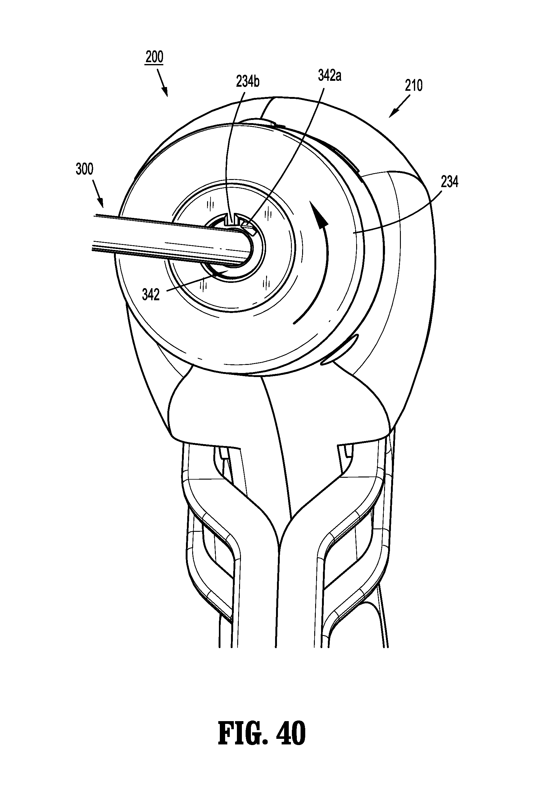
D00023

D00024
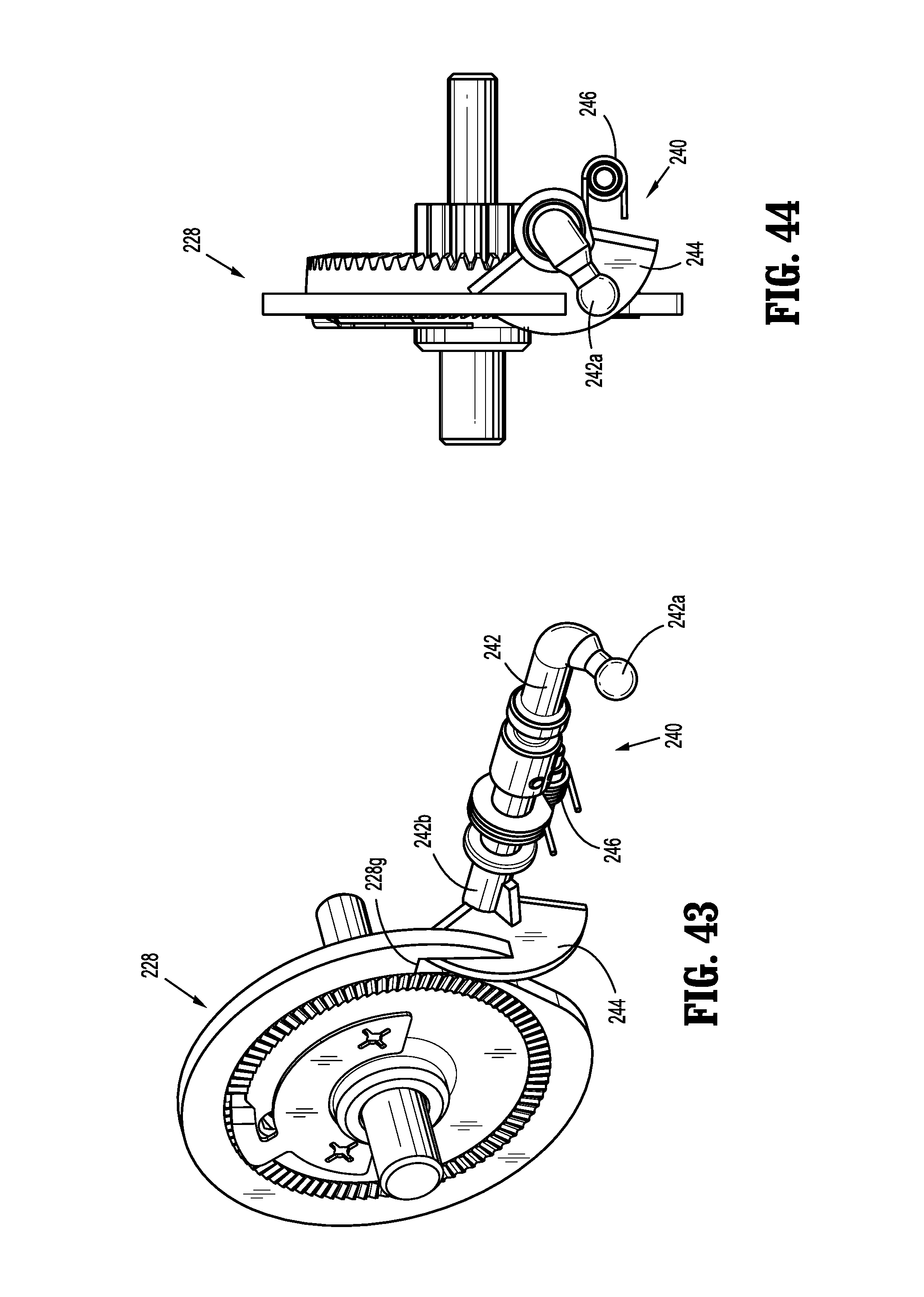
D00025

D00026

XML
uspto.report is an independent third-party trademark research tool that is not affiliated, endorsed, or sponsored by the United States Patent and Trademark Office (USPTO) or any other governmental organization. The information provided by uspto.report is based on publicly available data at the time of writing and is intended for informational purposes only.
While we strive to provide accurate and up-to-date information, we do not guarantee the accuracy, completeness, reliability, or suitability of the information displayed on this site. The use of this site is at your own risk. Any reliance you place on such information is therefore strictly at your own risk.
All official trademark data, including owner information, should be verified by visiting the official USPTO website at www.uspto.gov. This site is not intended to replace professional legal advice and should not be used as a substitute for consulting with a legal professional who is knowledgeable about trademark law.