Clinching punch and apparatus
Koenigbauer , et al.
U.S. patent number 10,328,481 [Application Number 14/217,870] was granted by the patent office on 2019-06-25 for clinching punch and apparatus. This patent grant is currently assigned to BTM Company LLC. The grantee listed for this patent is BTM Corporation. Invention is credited to Paul D. Boyes, Glenn R. Koenigbauer, Steven J. Sprotberry.


| United States Patent | 10,328,481 |
| Koenigbauer , et al. | June 25, 2019 |
Clinching punch and apparatus
Abstract
A clinching apparatus includes a clinching punch having a specifically dimensioned tapered surface which improves the strength of a clinch joint created therewith. In another aspect, a tapered surface adjacent a distal end of a clinching punch has an angle of 20-35.degree. relative to a distal end. A further aspect of a clinching apparatus provides a tapered surface adjacent a distal end which is configured in accordance with a specific formula.
| Inventors: | Koenigbauer; Glenn R. (Marine City, MI), Sprotberry; Steven J. (Marysville, MI), Boyes; Paul D. (Hillsborough, NZ) | ||||||||||
|---|---|---|---|---|---|---|---|---|---|---|---|
| Applicant: |
|
||||||||||
| Assignee: | BTM Company LLC (Marysville,
MI) |
||||||||||
| Family ID: | 52633172 | ||||||||||
| Appl. No.: | 14/217,870 | ||||||||||
| Filed: | March 18, 2014 |
Prior Publication Data
| Document Identifier | Publication Date | |
|---|---|---|
| US 20150266080 A1 | Sep 24, 2015 | |
| Current U.S. Class: | 1/1 |
| Current CPC Class: | B21D 37/20 (20130101); B21D 39/031 (20130101); Y10T 29/53996 (20150115) |
| Current International Class: | B23Q 1/00 (20060101); B21D 39/03 (20060101); B21D 37/20 (20060101) |
| Field of Search: | ;29/243.5,283.5 |
References Cited [Referenced By]
U.S. Patent Documents
| 567606 | September 1896 | McCool |
| 679137 | July 1901 | Baxter |
| 988154 | March 1911 | Thiemer |
| 1190696 | July 1916 | Wilzin |
| 1283799 | November 1918 | Kerr |
| 1456079 | May 1923 | Stuebner |
| 1509997 | September 1924 | Fry |
| 1919999 | July 1933 | Borton |
| 1926686 | September 1933 | Newton |
| 1969214 | August 1934 | Dit Daude |
| 1985333 | December 1934 | Wiley |
| 2004182 | June 1935 | Arey |
| 2254558 | September 1941 | Williams |
| 2278293 | March 1942 | Watson |
| 2333966 | November 1943 | Weiss |
| 2393986 | February 1946 | Gullberg |
| 2404197 | July 1946 | Sirp |
| 2430377 | November 1947 | Vorreyer |
| 2467969 | April 1949 | Debrot, Jr. |
| 2555836 | June 1951 | Werich |
| 2619855 | December 1952 | Williams |
| 2626687 | January 1953 | Williams |
| 2632929 | March 1953 | Poupitch |
| 2663072 | December 1953 | Pfistershamer |
| 2671361 | March 1954 | Sandberg |
| 2685719 | August 1954 | Golden |
| 2688890 | September 1954 | Wiiliams |
| 2713197 | July 1955 | Schmidt |
| 2811880 | November 1957 | Williams |
| 2865451 | December 1958 | Ihrig |
| 2924312 | February 1960 | Williams |
| 2937681 | May 1960 | Patten |
| 3022687 | February 1962 | Richards |
| 3157942 | November 1964 | MacLean, Jr. |
| 3177914 | April 1965 | MacLean |
| 3178749 | April 1965 | Heepe |
| 3187796 | June 1965 | Double |
| 3198155 | August 1965 | Fraze |
| 3202112 | August 1965 | Oakley |
| 3315345 | April 1967 | Double et al. |
| 3324491 | June 1967 | Gutshall |
| 3338463 | August 1967 | Henrickson |
| 3357388 | December 1967 | Dunn |
| 3359935 | December 1967 | Rosbottom |
| 3404648 | October 1968 | Rosbottom |
| 3439723 | April 1969 | Double et al. |
| 3451367 | June 1969 | Henrickson |
| 3465410 | September 1969 | Ernest et al. |
| 3469613 | September 1969 | Steward |
| 3470596 | October 1969 | Belada |
| 3506050 | April 1970 | Pouch et al. |
| 3579809 | May 1971 | Wolf et al. |
| 3599318 | August 1971 | Behlen |
| 3615274 | October 1971 | Belada |
| 3726000 | April 1973 | Hafner |
| 3730044 | May 1973 | Sawdon |
| 3740818 | June 1973 | Grube |
| 3771216 | November 1973 | Johnson |
| 3791016 | February 1974 | Eberhardt et al. |
| 3810290 | May 1974 | Grube |
| 3828517 | August 1974 | Johnson |
| 3829957 | August 1974 | Pouch et al. |
| 3862485 | January 1975 | Hafner |
| 3865047 | February 1975 | Hlinsky et al. |
| 3877133 | April 1975 | Grube |
| 3885299 | May 1975 | Hafner |
| 3900937 | August 1975 | Schleicher |
| 3919955 | November 1975 | DuVernay |
| 3920059 | November 1975 | Grube |
| 3921276 | November 1975 | Oaks |
| 3924378 | December 1975 | Hafner |
| 3934327 | January 1976 | Hafner |
| 3969808 | July 1976 | Goodsmith et al. |
| 3981064 | September 1976 | Hafner |
| 3999659 | December 1976 | Grube |
| 4035901 | July 1977 | Lux et al. |
| 4059897 | November 1977 | Marquis |
| 4064617 | December 1977 | Oaks |
| 4069902 | January 1978 | Zdeb |
| 4094352 | June 1978 | Hlinsky |
| 4153989 | May 1979 | Shinjo |
| 4196944 | April 1980 | Simatovich |
| 4203187 | May 1980 | Grube |
| 4208776 | June 1980 | Schleicher |
| 4237567 | December 1980 | Grube |
| 4242793 | January 1981 | Matthews et al. |
| 4269248 | May 1981 | MacLean et al. |
| 4281699 | August 1981 | Grube |
| 4306511 | December 1981 | Ashby et al. |
| 4384667 | May 1983 | Smallegan et al. |
| 4394794 | July 1983 | Shirey |
| 4410103 | October 1983 | Fuhrmeister |
| RE31535 | March 1984 | Schleicher |
| 4459735 | July 1984 | Sawdon |
| 4484385 | November 1984 | Woods |
| 4525912 | July 1985 | Kazino et al. |
| 4531279 | July 1985 | Gunter |
| 4569111 | February 1986 | Mutou |
| 4574453 | March 1986 | Sawdon |
| 4574473 | March 1986 | Sawdon |
| 4584753 | April 1986 | Eckold et al. |
| 4601090 | July 1986 | Gunter |
| 4610072 | September 1986 | Muller |
| 4614017 | September 1986 | Eckold et al. |
| 4633559 | January 1987 | Loren |
| 4658502 | April 1987 | Eckold et al. |
| 4660403 | April 1987 | Slasinski |
| 4688316 | August 1987 | La Barge et al. |
| 4722647 | February 1988 | Sawdon |
| 4752993 | June 1988 | Oaks |
| 4757609 | July 1988 | Sawdon |
| 4803767 | February 1989 | Obrecht et al. |
| 4825525 | May 1989 | Obrecht et al. |
| 4831704 | May 1989 | Rapp |
| 4831711 | May 1989 | Rapp |
| 4878284 | November 1989 | Sawdon |
| 4905362 | March 1990 | Obrecht et al. |
| 4910853 | March 1990 | Sawdon |
| 4928370 | May 1990 | Eckold et al. |
| 4930203 | June 1990 | Obrecht et al. |
| 4947719 | August 1990 | Whistler |
| 4972565 | November 1990 | Eckold et al. |
| 5010714 | April 1991 | Medwed et al. |
| 5027503 | July 1991 | Sawdon |
| 5031442 | July 1991 | Kynl |
| 5046228 | September 1991 | Eckold et al. |
| 5051020 | September 1991 | Schleicher |
| 5138758 | August 1992 | Gubbiotti et al. |
| 5150513 | September 1992 | Sawdon |
| 5155897 | October 1992 | Schleicher |
| 5177861 | January 1993 | Sawdon |
| 5207086 | May 1993 | Kynl |
| 5208973 | May 1993 | Sawdon |
| 5208974 | May 1993 | Sawdon et al. |
| 5230136 | July 1993 | Cronn et al. |
| 5259102 | November 1993 | Obrecht |
| 5267383 | December 1993 | Sawdon |
| 5305517 | April 1994 | Schleicher |
| 5315743 | May 1994 | Schleicher |
| 5338599 | August 1994 | Barrett |
| 5339509 | August 1994 | Sawdon et al. |
| 5408735 | April 1995 | Schleicher |
| 5425262 | June 1995 | Dubugnon |
| 5431089 | July 1995 | Sawdon |
| 5432989 | July 1995 | Turek |
| 5435049 | July 1995 | Sawdon |
| 5438897 | August 1995 | Chun |
| 5479687 | January 1996 | Sawdon |
| 5490310 | February 1996 | Schleicher |
| 5509290 | April 1996 | Faivre |
| 5528815 | June 1996 | Webb |
| 5581860 | December 1996 | Sawdon |
| 5621961 | April 1997 | Schleicher |
| 5622442 | April 1997 | Schleicher |
| 5695867 | December 1997 | Saitoh et al. |
| 5709019 | January 1998 | Sawdon |
| 5727302 | March 1998 | Sawdon |
| 5737819 | April 1998 | Sawdon et al. |
| 5782130 | July 1998 | Sawdon |
| 5806362 | September 1998 | Dubugnon |
| 5860315 | January 1999 | Sawdon |
| 5901601 | May 1999 | Fujimoto |
| 5946782 | September 1999 | Dubugnon et al. |
| 5984563 | November 1999 | Wu |
| 6062413 | May 2000 | Redmond |
| 6092270 | July 2000 | Sawdon |
| 6115898 | September 2000 | Sawdon |
| 6205640 | March 2001 | Dubugnon |
| 6430794 | August 2002 | McKee |
| 6430795 | August 2002 | Sawdon et al. |
| 6450082 | September 2002 | Sawdon |
| 6612007 | September 2003 | Wade |
| 6684479 | February 2004 | Wang et al. |
| 6757951 | July 2004 | Sawdon et al. |
| 6785959 | September 2004 | Sawdon et al. |
| 6961986 | November 2005 | Muller |
| 7003861 | February 2006 | Sawdon et al. |
| 7681296 | March 2010 | Rapp |
| 7694399 | April 2010 | Sawdon et al. |
| 8142098 | March 2012 | Hashimoto |
| 8261424 | September 2012 | Thomeczek |
| 8650730 | February 2014 | Sawdon |
| 8955364 | February 2015 | Breen |
| 2004/0045153 | March 2004 | Rapp |
| 2005/0252269 | November 2005 | Sawdon et al. |
| 2006/0096075 | May 2006 | Robinson |
| 2010/0018278 | January 2010 | Trojer et al. |
| 206465 | Jan 1957 | AU | |||
| 1237574 | Jun 1988 | CA | |||
| 98517 | Oct 1897 | DE | |||
| 2852909 | Jun 1980 | DE | |||
| 3021332 | Dec 1981 | DE | |||
| 3210208 | Sep 1983 | DE | |||
| 3613324 | Oct 1987 | DE | |||
| 3726392 | Feb 1989 | DE | |||
| 4214475 | Nov 1993 | DE | |||
| 4317278 | Dec 1993 | DE | |||
| 4335318 | Apr 1994 | DE | |||
| 642853 | Mar 1995 | EP | |||
| 2371252 | Jun 1978 | FR | |||
| 664979 | Jan 1952 | GB | |||
| 708236 | Apr 1954 | GB | |||
| 713625 | Aug 1954 | GB | |||
| 895561 | May 1962 | GB | |||
| 930164 | Jul 1963 | GB | |||
| 934101 | Aug 1963 | GB | |||
| 945110 | Dec 1963 | GB | |||
| 1008914 | Nov 1965 | GB | |||
| 1041119 | Sep 1966 | GB | |||
| 1101795 | Jan 1968 | GB | |||
| 1114826 | May 1968 | GB | |||
| 1551353 | Aug 1979 | GB | |||
| 2055648 | Mar 1981 | GB | |||
| S54107868 | Aug 1979 | JP | |||
| S54113753 | Sep 1979 | JP | |||
| S5659540 | May 1981 | JP | |||
| S62148035 | Jul 1987 | JP | |||
| S62148036 | Jul 1987 | JP | |||
| S62148039 | Jul 1987 | JP | |||
| S62148040 | Jul 1987 | JP | |||
| S63177931 | Jul 1988 | JP | |||
| S63192524 | Aug 1988 | JP | |||
| H04284928 | Oct 1992 | JP | |||
| 1299699 | Mar 1987 | SU | |||
| WO-9115316 | Oct 1991 | WO | |||
| WO-9314893 | Aug 1993 | WO | |||
| WO-9422613 | Oct 1994 | WO | |||
| WO-0136124 | May 2001 | WO | |||
Other References
|
Attexor Clinch Systems SA, "Clinching Products," .COPYRGT. 2002 [online], [retrieved on Nov. 7, 2008]. Retrieved from the Internet: http://www.clinchsystems.com/html, 22 pages. cited by applicant . Attexor Clinch Systems SA, "Clinching Tool Kits," .COPYRGT. 2002 [online], [retrieved on Oct. 28, 2008]. Retrieved from the Internet: http://www.clinchsystems.com/html. cited by applicant . Attexor Equipment, S.A., "Spot Clinch 67," 2 pages (prior to Jul. 22, 1994). cited by applicant . Attexor Supertagger, Sofort verbinden, ohne nieten, schrauben oder punktschweissen, 2 pages (published before Mar. 2014). cited by applicant . Bollhoff & Co, Verbindungs--und Montagetechnik, RIVSET.RTM. Stanzniettechnik, Standardsetzwerkzeuge, 2 pages (published before Mar. 2014). cited by applicant . Bollhoff & Co, Verbindungs--und Montagetechnik, RIVSET.RTM. Verbindung von Blechen und Profilen, 4 pages (published before Mar. 2014). cited by applicant . Bollhoff & Co, Verbindungs--und Montagetechnik, RIVSET-Stanzniettechnik, Proze uberwachung, 4 pages (published before Mar. 2014). cited by applicant . Bollhoff & Co, Verbindungs--und Montagetechnik, Systembeschreibung, RIVSET Magazinierte Stanzniete, 4 pages (published before Mar. 2014). cited by applicant . Bollhoff zum Thema Stanznieten, Warum sollen wir uns selbst loben, 4 pages (published before Mar. 2014). cited by applicant . BTM--Punch Tech Brochure, published Sep. 1983, 4 pages. cited by applicant . BTM Corporation Engineering Standards Manual--Section: D, Tog-L-Loc/Lance-N-Loc Information, Revised: Dec. 16, 2008, Rev 11, 46 pages. cited by applicant . BTM Corporation, "Typical Tog-L-Loc.RTM. Design Configurations," .COPYRGT. 2009 BTM Corporation, [online], [retrieved on Feb. 2, 2009]. Retrieved from the Internet: http://www.btmcorp.com/tlconfigure.html, 4 pages (published before Mar. 2014). cited by applicant . BTM Lance-N-Loc and Tog-L-Loc Brochure, published prior to May 10, 1994, 1 page. cited by applicant . BTM's Tog-L-Loc and Lance-N-Loc Brochure, "Sheet Metal Joining Systems," published 1999. 16 pages. cited by applicant . De-Sta-Co, Durchsetzfuge-Technik Brochure, published 1993, 4 pages. cited by applicant . J.M. Sawhill, Jr. and S.E. Sawdon, A New Mechanical Joining Technique for Steel Compared with Spot Welding, SAE Technical Paper Series 830128, Feb. 28-Mar. 4, 1983, 16 pages. cited by applicant . Pressotechnik GmbH, "TOX Druckfugetechnik," 2 pages, (prior to Jul. 22, 1994). cited by applicant . Pressotechnik, "TOX Sammanfogningssystem," 2 pages, (prior to Jul. 22, 1994). cited by applicant . Pressotechnik, "TOX-Clinch Technik," 4 pages, (prior to Jul. 22, 1994). cited by applicant . Tool Engineers Handbook, American Society of Tool Engineers Handbook Committee, Detroit MI, First Edition, 1949, Section 97 (Punches and Dies) and Section 98 (Jigs and Fixtures), 86 pages. cited by applicant . TOX--Sheet Metal Joining System: Riveting without Rivets Brochure, published Sep. 2005, 23 pages. cited by applicant . TOX publication 262 Nr 4.1 entitled "Werkzeuge und Werkzeugkenngro.beta.en," "Neue' Verbindungs-Verfahren im Vergleich," 2 pages (prior to Jul. 22, 1994). cited by applicant . BTM.RTM. Corporation; "Tog-L-Loc.RTM. Sheet Metal Joining System--Operating & Maintenance Manual;" 1988; 17 pages. cited by applicant . TOX.RTM. Pressotechnick L.L.C., "Overview of the TOX.RTM.--Clinching Technology--Data Sheet 80.100;" May 2008; 24 pages. cited by applicant . BTM Drawing No. 713800A entitiled "TL-3.0-940-N Punches" dated Nov. 21, 2013 (offered for sale in U.S. prior to Mar. 2014). cited by applicant. |
Primary Examiner: Hail; Joseph J
Assistant Examiner: McDonald; Shantese L
Attorney, Agent or Firm: Harness, Dickey & Pierce, PLC
Claims
The invention claimed is:
1. A clinching apparatus comprising: a linearly movable clinching punch including a side and an end, a taper located between the side and the end, the taper having an angle of 20-35 degrees relative to the end and the taper including an annular end view shape; the side, which is adapted to form an inside cavity of a clinch joint, being free of any step thereon; a holder secured to a proximal end of the punch; a stripper located adjacent a portion of the punch; a resilient member biasing the stripper away from the holder; a clinching die including a central anvil coaxially aligned with the punch, and upstanding die blades surrounding the anvil; and a clinch joint in multiple sheet metal workpieces created between the punch and the die; wherein the side and taper are dimensioned according to: .times..times..times. ##EQU00002## where 2E is a minor diameter of the side where the taper intersects the end, B is a major diameter of the side where the taper intersects the side, P.sub.thk is a nominal punch side-workpiece material thickness, and F is the angle of the taper.
2. The clinching apparatus of claim 1, wherein the multiple sheet metal workpieces are multiple appliance workpieces.
3. The clinching apparatus of claim 1, wherein: the multiple sheet metal workpieces are sheet steel workpieces; and an inside corner of the clinch joint includes a frusto-conical taper.
4. The clinching apparatus of claim 1, wherein the multiple sheet metal workpieces are sheet aluminum.
5. The clinching apparatus of claim 1, wherein the angle of the taper is 28-32 degrees relative to the end.
6. The clinching apparatus of claim 1, wherein the clinching end of the punch facing the die has a first peripheral diameter less than half of a second peripheral diameter of the proximal end of the punch opposite that of the clinching end.
7. The clinching apparatus of claim 1, wherein the multiple sheet metal workpieces are sheet steel workpieces of differing thicknesses clinched together by the punch and the die, and the clinch joint formed therebetween withstanding a peel force of at least twenty-five pounds, the workpieces being part of a washer or dryer appliance.
8. A clinching apparatus comprising: a linearly movable clinching punch including a side and an end, a taper located between the side and the end, the taper having an angle of 20-35 degrees relative to the end and the taper including an annular end view shape; a stripper located adjacent a portion of the punch; a resilient member biasing the stripper; a clinching die including a central anvil coaxially aligned with the punch, and upstanding die blades surrounding the anvil; and a clinch joint in multiple sheet metal workpieces created between the punch and the die; wherein the side and taper are dimensioned according to: .times..times..times. ##EQU00003## where 2E is a minor diameter of the side where the taper intersects the end, B is a major diameter of the side where the taper intersects the side, P.sub.thk is a nominal punch side-workpiece material thickness, and F is the angle of the taper.
9. The clinching apparatus of claim 8, wherein the multiple sheet metal workpieces are multiple appliance workpieces.
10. The clinching apparatus of claim 8, wherein: the multiple sheet metal workpieces are sheet steel workpieces; and an inside corner of the clinch joint includes a frusto-conical taper.
11. The clinching apparatus of claim 8, wherein the multiple sheet metal workpieces are sheet aluminum.
12. The clinching apparatus of claim 8, wherein the angle of the taper is 28-32 degrees relative to the end.
13. The clinching apparatus of claim 8, wherein the clinching end of the punch facing the die has a first peripheral diameter less than half of a second peripheral diameter of the proximal end of the punch opposite that of the clinching end.
14. The clinching apparatus of claim 8, wherein the multiple sheet metal workpieces are sheet steel workpieces of differing thicknesses clinched together by the punch and the die, and the clinch joint formed therebetween withstanding a peel force of at least twenty-five pounds, the workpieces being part of a washer or dryer appliance.
15. The clinching apparatus of claim 8, wherein the anvil is stationary relative to a surrounding cylindrical shield, and the die blades are moveable relative to the anvil and the shield.
16. The clinching apparatus of claim 8, wherein at least one of the workpieces is pre-painted prior to clinching contact between the punch and the die.
Description
BACKGROUND AND SUMMARY
The present invention relates generally to clinching apparatuses and more particularly to a clinching punch and joint formed therewith.
It is known to use a punch and die to create a clinch joint between workpiece sheets. Such a device is disclosed in U.S. Pat. No. 5,177,861 entitled "Apparatus for Joining Sheet Material" which issued to Sawdon on Jan. 12, 1993, and is commonly owned with the present application. This patent is incorporated by reference herein. This prior device was a significant step in the industry but there is still room for further improvements.
Another clinching construction is disclosed in U.S. Pat. No. 5,727,302 entitled "Die and Punch for Forming a Joint and Method of Making the Die" which issued to Sawdon on Mar. 17, 1998, and is commonly owned with the present application. This is also incorporated by reference herein. This prior punch includes a 5.degree. frusto-conical taper which was intended to advantageously prevent high stress concentrations and to improve the tool life during high pressure tool flexure misalignments.
In accordance with the present invention, a clinching apparatus includes a clinching punch having a specifically dimensioned tapered surface which improves the strength of a clinch joint created therewith. In another aspect, a tapered surface adjacent a distal end of a clinching punch has an angle of 20-35 degrees relative to a distal end. A further aspect of a clinching apparatus provides a tapered surface adjacent a distal end which is configured in accordance with a specific formula. Additional advantages and features of the present clinching apparatus can be ascertained from the following description and appended claims taken in conjunction with the present drawings.
BRIEF DESCRIPTION OF THE DRAWINGS
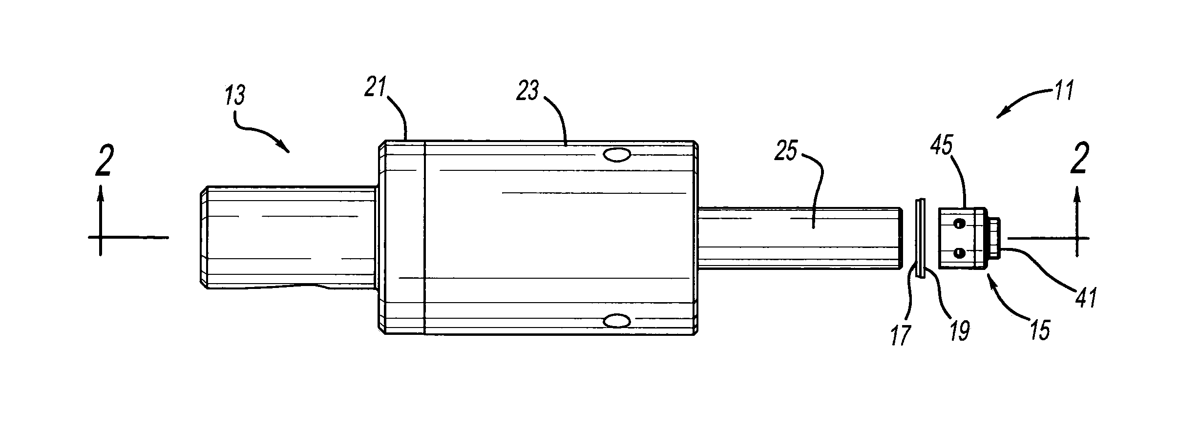
FIG. 1 is a side elevational view showing a clinching apparatus;
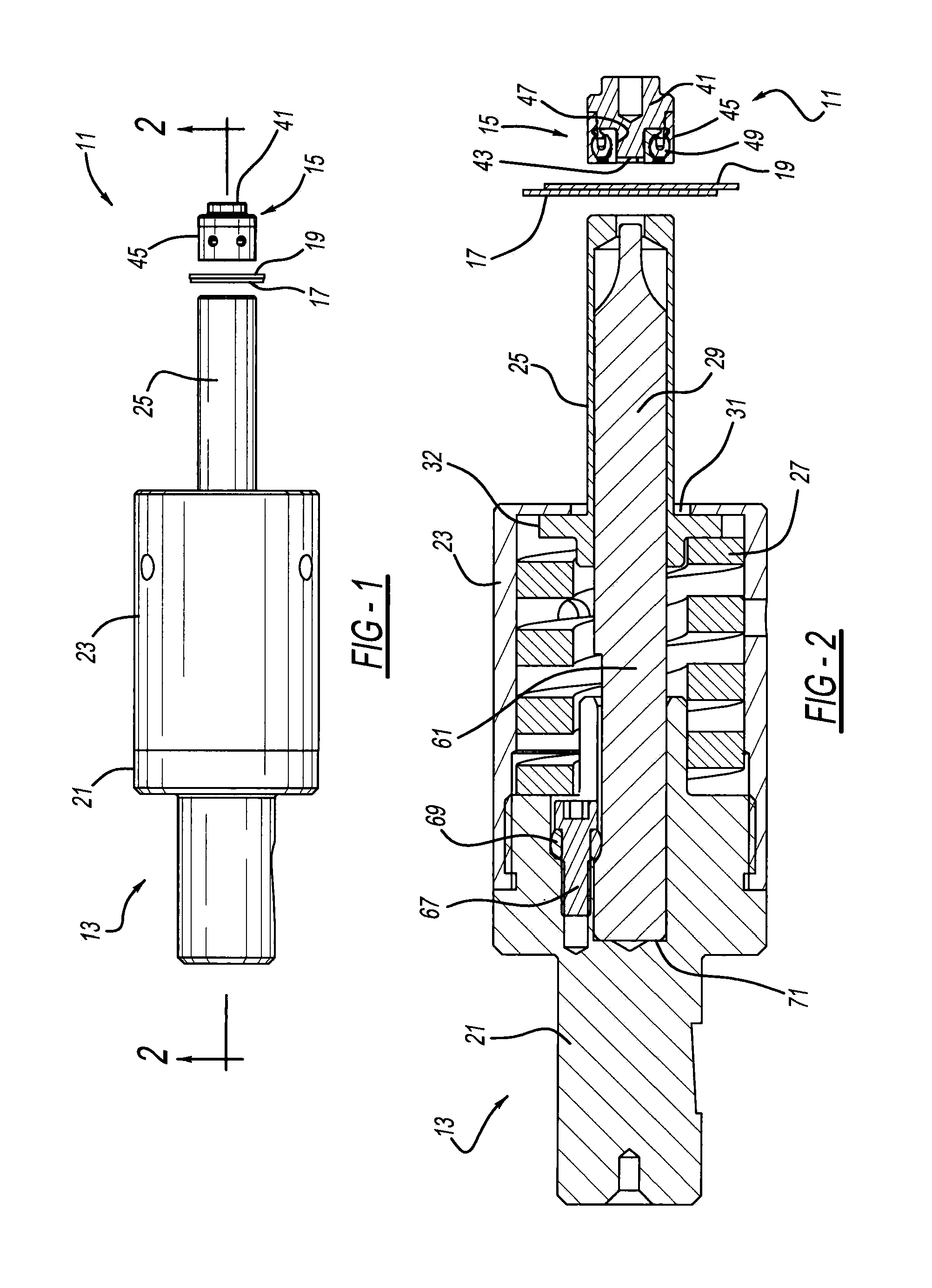
FIG. 2 is a cross-sectional view, taking along line 2-2 from FIG. 1, showing the clinching apparatus;
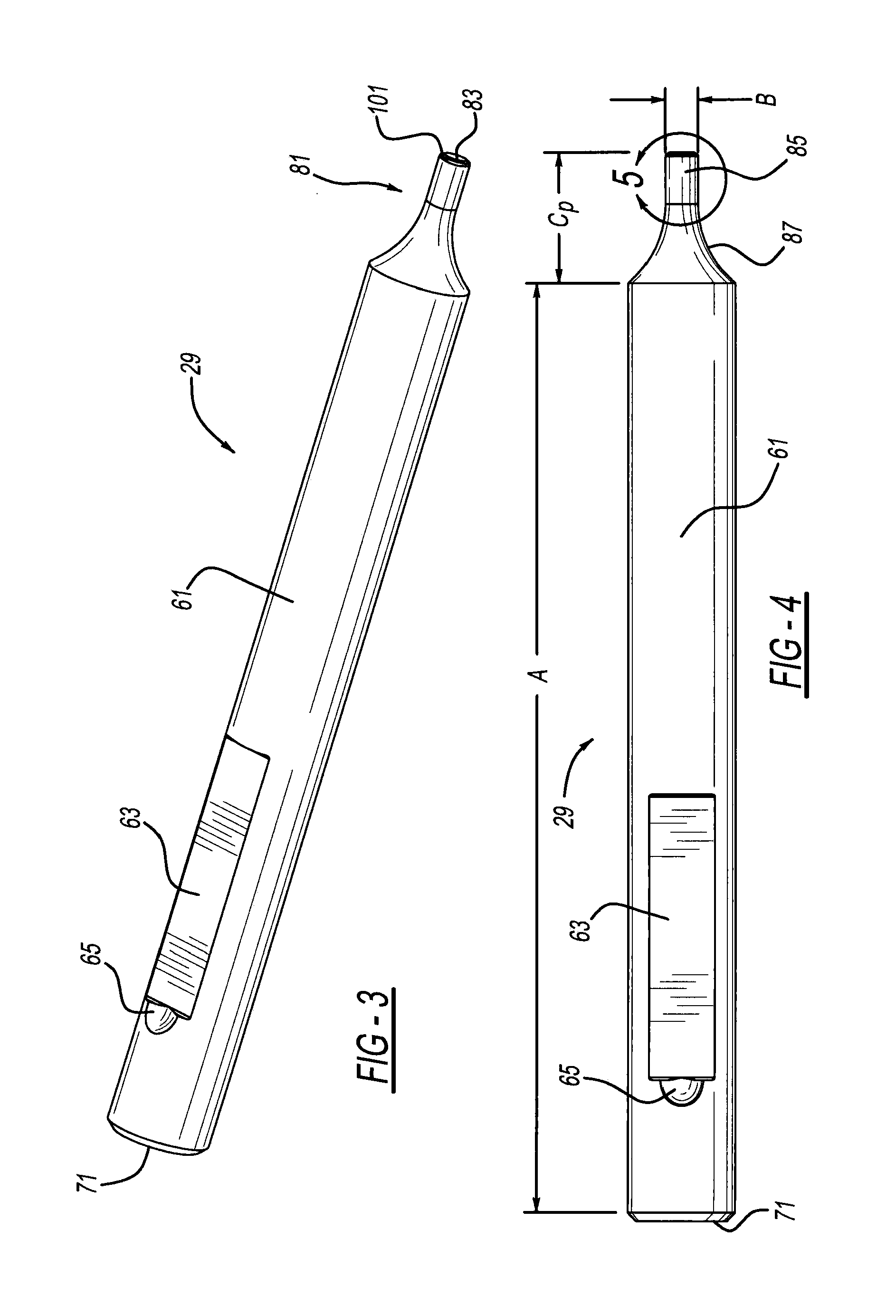
FIG. 3 is a perspective view showing a punch employed in the clinching apparatus;
FIG. 4 is a side elevational view showing the punch;
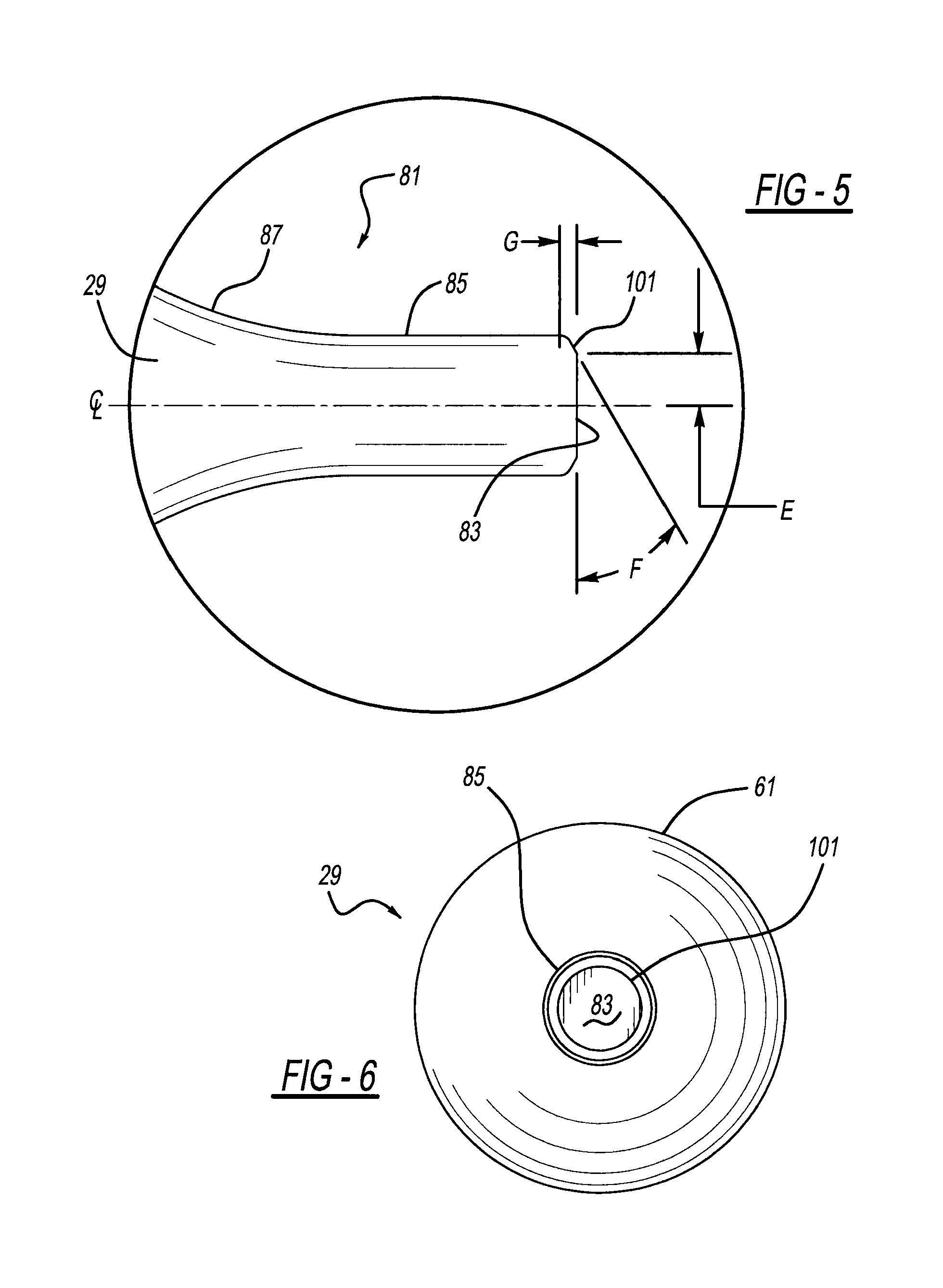
FIG. 5 is an enlarged side elevational view, taken within circle 5 from FIG. 4, showing the punch;
FIG. 6 is an end elevational view showing the punch; and
FIG. 7 is an enlarged diagrammatic view showing a clinch joint formed using the clinching apparatus.
DETAILED DESCRIPTION
Referring to FIGS. 1 and 2, a clinching apparatus 11 includes a punch assembly 13, a die assembly 15 and material workpiece sheets 17 and 19. Punch assembly 13 includes a punch holder 21, a hollow stripper retainer 23, a stripper 25, a helically coiled spring 27 and a punch 29. Retainer 23 is affixed to a periphery of holder 21, and stripper 25 is a hollow member, a section of which is linearly moveable through an aperture 31 of retainer 23. An axial length of stripper 25 is preferably greater than twice the diameter of an abutment flange 32 thereof. Spring 27 is located between flange 32 of stripper 25 and a facing surface of holder 21 so as to urge stripper 25 axially away from holder 21 but also allow stripper 25 to be compressed toward holder 21 during clinch joint forming when punch 29 is linearly advanced along its centerline and axial direction by a fluid powered actuator moving holder 21 and/or its attached frame. Exemplary actuators for moving either the punch or die are discussed in U.S. Pat. No. 6,115,898 entitled "Force Multiplying Apparatus for Clamping a Workpiece and Forming a Joint Therein" which issued to Sawdon on Sep. 12, 2000, and U.S. Pat. No. 8,650,730 entitled "Clinching Tool" which issued to Sawdon on Feb. 18, 2014, both of which are incorporated by reference herein.
Die 15 includes a body 41, and a fixed and stationary anvil 43 integrally upstanding from body 41. Furthermore, die 15 additionally includes a circular-cylindrical shield 45 attached to body 41 with a set of three movable die blades 47 located between a generally cylindrical side of anvil 43 and shield 45. A coiled spring 49, elastomeric O-ring or other biasing member is located between shield 45 and blades 47 so as to urge distal ends of the die blades toward the side of anvil 43. Punch holder 21 and die body 41 are fastened to a C-frame, fixture or other mechanism such that punch 29 and anvil 43 are always intended to be aligned with each other in all joint forming operating conditions in the preferred embodiment of the present punching apparatus.
Reference should now be made to FIGS. 2-6. Punch 29 includes a generally circular-cylindrical body 61 which is elongated in an axial direction defined by a centerline CL of the punch. A recess 63 has an axially elongated shape machined in a peripheral surface of body 61 with a partially spherical depression 65 located at a trailing end thereof. A threaded fastener 67 and surrounding partially spherical retention ball or collar 69 engage with recess 65 to secure punch 29 to holder 21 in a removable manner such that a proximal or trailing end 71 of punch 29 firmly abuts against holder 21.
Punch 29 further includes a clinch joint-forming tip 81 which ends in a distal or leading end 83. Tip 81 of punch 29 further includes a generally circular-cylindrical peripheral side surface 85 which is located between distal end 83 and an arcuately curved transition section 87. Distal end 83 and a section with surface 85 are the portions of punch 29 that enter into and create a recessed cup for the clinch joint in a punching and deforming action. It is noteworthy that surface 85 has a generally constant diameter B without any discontinuities or steps therein. Alternately, a very small draft angle can be provided on surface 85, but generally equal to 5.degree. relative to the punch centerline. Moreover, arcuately curved section 87 may alternately have a frusto-conical shape thereto although various workpiece deformation or punch strength benefits may not be achieved.
A frusto-conical taper 101, annular in an end view, is located between distal end 83 and cylindrical side surface 85. Taper 101 preferably has an angle F of 20-35 degrees relative to end 83, more preferably 28-32 degrees, and most preferably 30 degrees for two workpieces 17 and 19 of differing thicknesses. Intersecting lines defined between sidewall surface 85, taper 101 and distal end 83 all have angular corners in one version, however, it is alternately envisioned that one or both of the intersecting corners can employ a radius no greater than 0.02 inch. Furthermore, N is a sidewall neck thickness NL or NR of punch-side workpiece 17, A is an axial length of body 61 of punch 29, E is a minor radius measured between centerline CL of punch 29 and an intersection between tapered surface 101 and distal end 83, t.sub.1 is a minimum thickness of punch-side workpiece 17 at the bottom or button of the final clinch joint, and t.sub.2 is a minimum thickness of die-side workpiece 19 at the bottom or button of the final clinch joint.
Additionally, angle F for taper 101 of punch 29 is preferably determined according to the following formula regarding the desired final clinch joint 111 as illustrated in FIG. 7:
.times..times..times. ##EQU00001## where 2E is a minor diameter of side surface 85 where the tapered surface intersects distal end 83, B is a major diameter of side surface 85 where tapered surface 101 intersects side surface 85, P.sub.thk is a nominal (unclinched) punch-side workpiece 17 material thickness, and F is the angle of tapered surface 101.
The angular dimensions for the present taper 101 have been found to be significantly superior in joint performance as compared to conventional punch tips which have no taper or a mere 5.degree. transitional taper, especially for a workpiece arrangement where punch-side workpiece 17 is less than half the nominal thickness of die-side workpiece 19 as measured prior to joint formation. One such arrangement is where workpieces 17 and 19 are mating components or housings in a refrigerator appliance, or alternately an oven appliance, a dish washer appliance, a clothes washer appliance, a clothes dryer appliance or the like. The specific tip dimensional ranges disclosed herein have been found to better control the workpiece material flow throughout the duration of the material joining process, especially creating a more constant and thicker punch-side workpiece thickness NL and NR at the most inwardly constricted diameter 113 of die-side workpiece 19 where the workpieces interlock together after full clinch joint formation. The further interlocking deformation areas are at LL and LR. In contrast, a traditional punch with no taper at the end-to-sidewall transition is prone to causing undesired tearing or piercing of the punch-side workpiece adjacent constricted diameter 113.
By way of further comparison for one example of the present apparatus, workpieces 17 (HRB 55, textured pre-painted) and 19 (HRB 60) are both steel, where the punch-side workpiece has a nominal thickness of 0.19 inch and the die-side workpiece has a nominal thickness of 0.40 inch, clinched together by a punch with taper angle F of 30.degree.. This construction was found to have a finished clinch joint peel strength of at least 25 pounds of force and with a shear strength of at least 75 pounds, while the conventional and untapered punch version had a peel strength of less than 15 pounds of force. In another example, 0.026 inch nominally thick stainless steel (HRB 71) was used for punch-side workpiece 17 with HRB 55 steel of 0.40 inch nominal thickness for die-side workpiece 19; this generated a peel strength of at least 60 pounds and a shear strength of at least 185 pounds for a 30.degree. taper angle F on punch 29. In these examples, a diameter C.sub.B of a clinch joint outer button circular periphery is 0.188 inch, a button cap height Z is 0.038 inch, and a total button bottom thickness X is 0.021 inch. Furthermore, the preceding examples employed punch 29 with dimensions of A=3.937 inch, B=0.120 inch, C.sub.p=0.480, E=0.044, F=30.degree. and G=0.015 inch. It should be appreciated that these dimensions are simply exemplary and the dimensions may vary (although the joint performance may also then vary).
While the preferred embodiment of the present clinching apparatus has been disclosed, it should be appreciated that other variations are possible. For example, while three movable die blades have been disclosed, it should be appreciated that two, four or other quantities of die blades surrounding or partially surrounding an anvil of the die assembly may be employed although certain advantages of the present die may not be realized. Furthermore, a punch of a polygonal body periphery can alternately be used although certain manufacturing and cost advantages may not be obtained. The shapes of the punch holder, stripper, spring and stripper retainer can be varied, however, various advantages may not be realized. A moving anvil, fixed die blades, and the absence of the disclosed shield may alternately be used, although such an arrangement would forego many advantageous features of the present device. Additionally, aluminum and other workpiece materials may be employed with the present clinching apparatus although the exact dimensions may need to be slightly varied to account for the material flow differences. It should be appreciated that other modifications and variations may be made to the preferred apparatus without departing from the spirit and scope of the present invention.
* * * * *
References
D00000
D00001
D00002
D00003
D00004
M00001
M00002
M00003
XML
uspto.report is an independent third-party trademark research tool that is not affiliated, endorsed, or sponsored by the United States Patent and Trademark Office (USPTO) or any other governmental organization. The information provided by uspto.report is based on publicly available data at the time of writing and is intended for informational purposes only.
While we strive to provide accurate and up-to-date information, we do not guarantee the accuracy, completeness, reliability, or suitability of the information displayed on this site. The use of this site is at your own risk. Any reliance you place on such information is therefore strictly at your own risk.
All official trademark data, including owner information, should be verified by visiting the official USPTO website at www.uspto.gov. This site is not intended to replace professional legal advice and should not be used as a substitute for consulting with a legal professional who is knowledgeable about trademark law.