Apparatus and method of charging mobile terminal using energy harvesting device
Kim , et al.
U.S. patent number 10,326,312 [Application Number 15/351,651] was granted by the patent office on 2019-06-18 for apparatus and method of charging mobile terminal using energy harvesting device. This patent grant is currently assigned to Industry-Academic Cooperation Foundation, Chosun University. The grantee listed for this patent is Industry-Academic Cooperation Foundation, Chosun University. Invention is credited to Jong Jin Baek, Min Joo Jeong, Se Woong Kim, Youn Tae Kim, Jang Hyun Lee, Kun Ho Park.


| United States Patent | 10,326,312 |
| Kim , et al. | June 18, 2019 |
Apparatus and method of charging mobile terminal using energy harvesting device
Abstract
An apparatus for charging a mobile terminal includes an energy harvesting device provided in shoes and generating energy generated by a movement of a human body, a charge control module attached to trousers and controlling charging of a mobile terminal using energy harvested by the energy harvesting device, and a resonant coil module wirelessly transmitting energy harvested by the energy harvesting device to the charge control module, wherein the resonant coil module includes a transmission resonant coil unit provided in the shoes and a reception resonant coil unit provided in the trousers, spaced apart from the transmission resonant coil unit by a predetermined distance, and magnetically coupled to the transmission resonant coil unit.
| Inventors: | Kim; Youn Tae (Daejeon, KR), Jeong; Min Joo (Gwangju, KR), Park; Kun Ho (Goheung-gun, KR), Baek; Jong Jin (Gwangyang-si, KR), Lee; Jang Hyun (Siheung-si, KR), Kim; Se Woong (Gwangju, KR) | ||||||||||
|---|---|---|---|---|---|---|---|---|---|---|---|
| Applicant: |
|
||||||||||
| Assignee: | Industry-Academic Cooperation
Foundation, Chosun University (Gwangju, KR) |
||||||||||
| Family ID: | 59856077 | ||||||||||
| Appl. No.: | 15/351,651 | ||||||||||
| Filed: | November 15, 2016 |
Prior Publication Data
| Document Identifier | Publication Date | |
|---|---|---|
| US 20170271922 A1 | Sep 21, 2017 | |
Foreign Application Priority Data
| Mar 17, 2016 [KR] | 10-2016-0032004 | |||
| Current U.S. Class: | 1/1 |
| Current CPC Class: | H02J 7/35 (20130101); H02J 50/001 (20200101); A43B 3/0005 (20130101); H02J 50/12 (20160201); H02N 2/186 (20130101); H02J 7/025 (20130101); A43B 3/0015 (20130101); H02N 2/188 (20130101); H01L 35/28 (20130101) |
| Current International Class: | H02J 7/02 (20160101); H02J 50/12 (20160101); H02J 7/35 (20060101); H01L 35/28 (20060101); H02N 2/18 (20060101); A43B 3/00 (20060101) |
| Field of Search: | ;320/108 |
References Cited [Referenced By]
U.S. Patent Documents
| 4760355 | July 1988 | Dash |
| 6411016 | June 2002 | Umeda |
| 7078850 | July 2006 | Sakai |
| 7154449 | December 2006 | Liu |
| 8308489 | November 2012 | Lee |
| 8319401 | November 2012 | McKenna |
| 8348504 | January 2013 | Gregory |
| 8476778 | July 2013 | Weinberger |
| 8568026 | October 2013 | Gregory |
| 8663106 | March 2014 | Stivoric |
| 9143060 | September 2015 | Tseng |
| 9204806 | December 2015 | Stivoric |
| 9232331 | January 2016 | Priyantha |
| 9279734 | March 2016 | Walker |
| 9297709 | March 2016 | Dojan |
| 9331559 | May 2016 | Shastry |
| 9360946 | June 2016 | Priyantha |
| 9410857 | August 2016 | Walker |
| 9520921 | December 2016 | Pagani |
| 9541941 | January 2017 | Ramorini |
| 9572395 | February 2017 | Roser |
| 9614371 | April 2017 | Farkas |
| 9762710 | September 2017 | Lee |
| 9810591 | November 2017 | Walker |
| 9859747 | January 2018 | Hwang |
| 9888337 | February 2018 | Zalewski |
| 9894471 | February 2018 | Zalewski |
| 10015294 | July 2018 | Lee |
| 10148118 | December 2018 | Hwang |
| 2004/0041498 | March 2004 | Sakai |
| 2005/0179604 | August 2005 | Liu |
| 2005/0245839 | November 2005 | Stivoric |
| 2006/0017353 | January 2006 | Sakai |
| 2007/0100666 | May 2007 | Stivoric |
| 2008/0161715 | July 2008 | Stivoric |
| 2008/0167535 | July 2008 | Stivoric |
| 2008/0167572 | July 2008 | Stivoric |
| 2008/0167573 | July 2008 | Stivoric |
| 2008/0214949 | September 2008 | Stivoric |
| 2010/0100997 | April 2010 | Lee et al. |
| 2010/0201312 | August 2010 | Kirby |
| 2011/0280279 | November 2011 | Gregory |
| 2012/0049538 | March 2012 | Periasamy |
| 2013/0019503 | January 2013 | Vogt |
| 2013/0020986 | January 2013 | Linzon |
| 2013/0125386 | May 2013 | Gregory |
| 2013/0188341 | July 2013 | Tseng |
| 2013/0263349 | October 2013 | Roser |
| 2013/0324041 | December 2013 | Pagani |
| 2014/0015470 | January 2014 | Lim |
| 2014/0203797 | July 2014 | Stivoric |
| 2014/0232516 | August 2014 | Stivoric |
| 2014/0312834 | October 2014 | Tanabe |
| 2015/0200554 | July 2015 | Marks |
| 2015/0214823 | July 2015 | Shastry |
| 2015/0234416 | August 2015 | Ramorini |
| 2015/0326985 | November 2015 | Priyantha |
| 2016/0058076 | March 2016 | Reho |
| 2016/0116988 | April 2016 | Priyantha |
| 2016/0190860 | June 2016 | Swift |
| 2016/0211064 | July 2016 | Choi |
| 2016/0248312 | August 2016 | Shastry |
| 2016/0250099 | September 2016 | Eim |
| 2016/0351771 | December 2016 | Schneider |
| 2017/0025857 | January 2017 | Matthews |
| 2017/0027278 | February 2017 | Roser |
| 2017/0048363 | February 2017 | Lee |
| 2017/0070078 | March 2017 | Hwang |
| 2017/0093024 | March 2017 | Pagani |
| 2017/0106277 | April 2017 | Perdigon Rodriguez |
| 2017/0156594 | June 2017 | Stivoric |
| 2017/0201099 | July 2017 | Savanth |
| 2017/0374182 | December 2017 | Lee |
| 2018/0069420 | March 2018 | Hwang |
| 2018/0073168 | March 2018 | Gladish |
| 2018/0146739 | May 2018 | Malhotra |
| 2018/0188114 | July 2018 | Ou Yang |
| 1020130092758 | Aug 2013 | KR | |||
| 2016-0019249 | Feb 2016 | KR | |||
Assistant Examiner: Trischler; John T
Attorney, Agent or Firm: Renner, Otto, Boisselle & Sklar, LLP
Claims
What is claimed is:
1. An apparatus for charging a mobile terminal, the apparatus comprising: an energy harvesting device provided in shoes and generating energy generated by a movement of a human body; a charge control module attached to trousers and controlling charging of a mobile terminal using energy harvested by the energy harvesting device; and a resonant coil module wirelessly transmitting energy harvested by the energy harvesting device to the charge control module, wherein the resonant coil module includes a transmission resonant coil unit provided in the shoes and a reception resonant coil unit provided in the trousers, spaced apart from the transmission resonant coil unit, and magnetically coupled to the transmission resonant coil unit, and wherein the transmission resonant coil unit is wound along a circumference of the topline of the shoes; wherein the reception resonant coil unit is wound along a circumference of the cuffs of the trousers; wherein the transmission resonant coil is wound in at least one of a spiral shape, an up/down zigzag shape, and a helical shape; and wherein the reception resonant coil is wound in at least one of a spiral shape, an up/down zigzag shape, and a helical shape.
2. The apparatus of claim 1, further comprising a conductive thread transmitting energy wirelessly received by the reception resonant coil unit to the charge control module, wherein the conductive thread is formed by doubling and twisting a copper wire and thread, and woven in the trousers in fabric form.
3. The apparatus of claim 1, further comprising: a rectifying unit converting energy harvested by the energy harvesting device into direct current (DC) power; and an oscillation unit oscillating the DC power rectified by the rectifying unit to have the same frequency as a resonant frequency of the transmission resonant coil unit.
4. The apparatus of claim 1, wherein the energy harvesting device includes at least one of a piezoelectric device converting pressure applied according to a movement of the human body into energy and a capacitive device converting state electricity generated according to a movement of the human body into energy.
5. The apparatus of claim 1, wherein the transmission resonant coil unit and the reception resonant coil unit include a conductive thread obtained by doubling and twisting a copper wire and thread and woven in the shoes or the trousers in fabric form.
6. The apparatus of claim 1, wherein a resonant frequency of the transmission resonant coil unit is in inverse proportion to a length of the transmission resonant coil unit.
7. The apparatus of claim 1, wherein the transmission resonant coil unit includes a primary coil having one winding and a transmission resonant coil disposed to be spaced apart from the primary coil by a predetermined distance and having at least two windings, and the reception resonant coil unit includes a reception resonant coil having at least two windings and a secondary coil disposed to be spaced apart from the reception resonant coil by a predetermined distance and having one winding.
8. The apparatus of claim 1, wherein the charge control module comprises: a controller controlling charging of the mobile terminal using energy harvested by the energy harvesting device; and a sensing unit sensing contact with the human body, wherein the controller starts or stops charging according to a sensing result from the sensing unit.
9. The apparatus of claim 8, wherein the sensing unit senses a change in a resistance value due to contact with the human body or a change in capacitance due to contact with the human body.
10. A method of charging a mobile terminal, the method comprising: generating, by an energy harvesting device provided in shoes, energy generated by a movement of a human body; wirelessly transmitting, by a resonant coil module, energy harvested by the energy harvesting device, to a charge control module; and controlling, by the charge control module attached to trousers, charging of a mobile terminal using energy harvested by the energy harvesting device, wherein the resonant coil module includes a transmission resonant coil unit provided in the shoes and a reception resonant coil unit provided in the trousers, spaced apart from the transmission resonant coil unit, and magnetically coupled to the transmission resonant coil unit, a conductive thread is provided between the resonant coil module and the wireless charge module, the conductive thread is obtained by doubling and twisting a copper wire and thread, and woven in the trousers in fabric form, and wherein the transmission resonant coil unit is wound along a circumference of the topline of the shoes; wherein the reception resonant coil unit is wound along a circumference of the cuffs of the trousers; wherein the transmission resonant coil is wound in at least one of a spiral shape, an up/down zigzag shape, and a helical shape; and wherein the reception resonant coil is wound in at least one of a spiral shape, an up/down zigzag shape, and a helical shape.
Description
CROSS-REFERENCE TO RELATED APPLICATION
This application claims benefit of priority to Korean Patent Application No. 10-2016-0032004 filed on Mar. 17, 2016 in the Korean Intellectual Property Office, the disclosure of which is incorporated herein by reference in its entirety.
BACKGROUND
1. Field
The present disclosure relates to an apparatus and method of charging a mobile terminal using an energy harvesting device.
The present disclosure is derived from (i) research conducted by a university ICT research center fostering work by the Ministry of Science ICT and Future Planning: [Project No.: 1711026714(R0992-15-1021), Project title: Development of Technology of Energy Harvesting for Wearable Device and Wireless Power Transmission] and (ii) research conducted by National Research Foundation(NRF) of KOREA grant founded by the Ministry of Education and Science Technology (MEST) through Mid-career Research Program: [Project No.: 2016R1A2B3009423].
2. Description of Related Art
Energy harvesting technology, harvesting energy discarded nearby and converting it into electrical energy to use, is expected to be prominent as a future industrial technology field promoting the preservation of the natural environment.
When used in existing electronic devices, or the like, such technology may allow electronic devices to be independently driven using nearby energy without the necessity of charging a battery using a separate power source, as well as significantly enhancing energy efficiency. Also, this technology has potentially wide application coverage for use as a power source or an auxiliary power source for various sensors and communication devices using the same.
The energy harvesting technology may be classified as harvesting solar energy from sunlight, harvesting thermoelectric energy to produce electrical energy using the Seebeck effect, based on a temperature difference, and harvesting piezoelectric energy to obtain electrical energy from sources of kinetic energy such as ambient vibrations or impacts.
Here, piezoelectric energy harvesting technology in which energy is obtained from a movement (or a motion) of a human body using a piezoelectric material attached to a user's skin or a user's clothes or footwear, such as shoes, converts vibrations or impacts, far smaller than those found in existing waterpower generation, thermal power generation, wind power generation, and tidal power generation using magnets, into electric energy, even in dark areas or a night without the presence of sunlight, and has high energy conversion efficiency.
Piezoelectric energy harvesting technology is commonly encountered in the igniters of gas lighters and gas stoves that people frequently use, and is anticipated to be extensively applied to applications in devices such as power storage devices of mobile devices, power generators of streetlights or emergency stairways, micropiezoelectric generators of micro-miniature devices, artificial internal organs as well as health examination devices, office remote control systems, structure diagnosing systems using wireless sensors, and the like.
Similar to the piezoelectric energy harvesting technology is an electrostatic energy harvesting technology obtaining energy by repetitively inducing triboelectrification in objects. According to this technology, electricity is generated on a contact surface through friction and the electricity generated thereby is stored and utilized in generators, having advantages in allowing harvesting devices obtaining a high energy output to be manufactured at relatively low cost, without an environmental contamination element.
Such harvesting technology may be applied to energy harvesting based on activities of the human body, and to this end, the piezoelectric energy harvesting technology and the electrostatic energy harvesting technology, among various harvesting technologies, may be used. A great amount of energy may be obtained from the motions of walking or running from among various human body activities, and piezoelectric devices formed of materials such as dielectric elastic composites, dielectric elastomers, polyvinylidene fluoride (PVDF), and the like, may be placed on the bottom of shoes to convert pressure applied to the devices due to the motions of walking or running into energy to thus harvest the energy. When a device with a high degree of electrification (or chargeability) is positioned in shoes and repetitive friction based on human body activities is induced, electricity may be generated on a contact surface of the device with high electrification through interfacial friction of a material, thereby allowing energy to be harvested. Related art is Korean Patent Laid-Open Publication No. 2013-0092758 (Entitled: "Self-power Generation Device of Shoe Sole, publication date: Aug. 21, 2013).
RELATED ART DOCUMENT
(Patent Document 1) Korean Patent Laid-Open Publication No. 2013-0092758 (Entitled: "Self-power Generation Device of Shoe Sole, publication date: Aug. 21, 2013)
SUMMARY
An aspect of the present disclosure may provide an apparatus and method of charging a mobile terminal using an energy harvesting device, capable of effectively charging a mobile terminal using energy generated according to a movement of a human body and minimizing discomfort that users may feel in charging the mobile terminal.
According to an aspect of the present disclosure, an apparatus for charging a mobile terminal may include: an energy harvesting device provided in shoes and generating energy generated by a movement of a human body; a charge control module attached to trousers and controlling charging of a mobile terminal using energy harvested by the energy harvesting device; and a resonant coil module wirelessly transmitting energy harvested by the energy harvesting device to the charge control module, wherein the resonant coil module includes a transmission resonant coil unit provided in the shoes and a reception resonant coil unit provided in the trousers, spaced apart from the transmission resonant coil unit by a predetermined distance, and magnetically coupled to the transmission resonant coil unit.
The apparatus may further include: a conductive thread transmitting energy wirelessly received by the reception resonant coil unit to the charge control module, wherein the conductive thread may be formed by doubling and twisting a copper wire and thread, and woven in the trousers in fabric form.
The apparatus may further include: a rectifying unit converting energy harvested by the energy harvesting device into direct current (DC) power; and an oscillation unit oscillating the DC power rectified by the rectifying unit to have the same frequency as a resonant frequency of the transmission resonant coil unit.
The energy harvesting device may include at least one of a piezoelectric device converting pressure applied according to a movement of the human body into energy and a capacitive device converting state electricity generated according to a movement of the human body into energy.
The transmission resonant coil unit and the reception resonant coil unit may include a conductive thread obtained by doubling and twisting a copper wire and thread and woven in the shoes or the trousers in fabric form.
The transmission resonant coil unit may be provided in a topline of the shoes to surround an ankle of the wearer, and the reception resonant coil unit may be provided in cuffs of the trousers.
The transmission resonant coil unit may be provided on an inner or outer side of the shoes, and the reception resonant coil unit may be provided in a position corresponding to a position of the transmission resonant coil unit, on an inner or outer side of the trousers.
The transmission resonant coil unit and the reception resonant coil unit may be wound in at least one of a spiral shape, an up/down zigzag shape, and a helical shape along a circumference of the topline of the shoes or the cuffs of the trousers.
The transmission resonant coil unit and the reception resonant coil unit may be spirally wound a plurality of times along a quadrangular or circular circumference on a plane.
A resonant frequency of the transmission resonant coil unit may be in inverse proportion to a length of the transmission resonant coil unit.
The charge control module may include: a controller controlling charging of the mobile terminal using energy harvested by the energy harvesting device; and a sensing unit sensing contact with the human body, wherein the controller may start or stop charging according to a sensing result from the sensing unit.
The sensing unit may sense a change in a resistance value due to contact with the human body or a change in capacitance due to contact with the human body.
According to another aspect of the present disclosure, a method of charging a mobile terminal may include: generating, by an energy harvesting device provided in shoes, energy generated by a movement of a human body; wirelessly transmitting, by a resonant coil module, energy harvested by the energy harvesting device, to a charge control module; and controlling, by the charge control module attached to trousers, charging of a mobile terminal using energy harvested by the energy harvesting device, wherein the resonant coil module includes a transmission resonant coil unit provided in the shoes and a reception resonant coil unit provided in the trousers, spaced apart from the transmission resonant coil unit by a predetermined distance, and magnetically coupled to the transmission resonant coil unit, a conductive thread is provided between the resonant coil module and the wireless charge module, and the conductive thread is obtained by doubling and twisting a copper wire and thread, and woven in the trousers in fabric form.
BRIEF DESCRIPTION OF DRAWINGS
The above and other aspects, features and other advantages of the present disclosure will be more clearly understood from the following detailed description taken in conjunction with the accompanying drawings, in which:
FIGS. 1A AND 1B are a view illustrating a configuration of a charging device of a mobile terminal using an energy harvesting device according to an exemplary embodiment in the present disclosure;
FIGS. 2A-2G are a view illustrating various exemplary embodiments of a resonant coil module according to an exemplary embodiment in the present disclosure;
FIG. 3 is a view illustrating a configuration of a charge control module according to an exemplary embodiment in the present disclosure; and
FIG. 4 is a flow chart illustrating a method of charging a mobile terminal using an energy harvesting device according to an exemplary embodiment in the present disclosure.
DETAILED DESCRIPTION
Exemplary embodiments of the present disclosure will now be described in detail with reference to the accompanying drawings.
FIGS. 1A and 1B are a view illustrating a configuration of a charging device of a mobile terminal using an energy harvesting device according to an exemplary embodiment in the present disclosure, FIGS. 2A-2G are a view illustrating various exemplary embodiments of a resonant coil module according to an exemplary embodiment in the present disclosure, and FIG. 3 is a view illustrating a configuration of a charge control module according to an exemplary embodiment in the present disclosure.
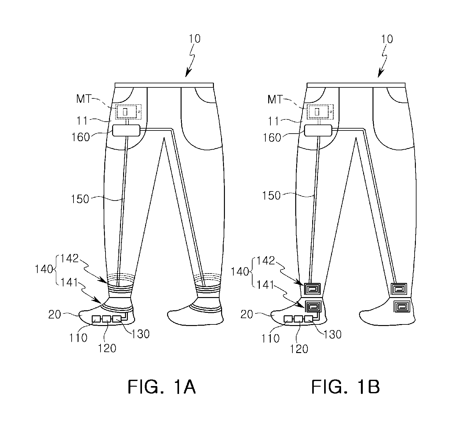
As illustrated in FIGS. 1A and 1B, according to an apparatus for charging a mobile terminal of an exemplary embodiment, shoes 20 may include an energy harvesting device 110, a rectifying unit 120, and an oscillation unit 130, and the trousers 10 may include a conductive thread 150 and a charge control module 160 and may further include a resonant coil module 140 wirelessly transmitting energy harvested by the energy harvesting device 110 to the charge control module 160.
The resonant coil module 140 may include a transmission resonant coil unit 141 provided in a topline of the shoes 20 and a reception resonant coil unit 142 provided in cuffs of the trousers 10. FIG. 1A illustrates a configuration in which the resonant coil module 140 is wound to have a circular shape and FIG. 1B illustrates a configuration in which the resonant coil 140 is wound on a plane. In FIG. 1B, the transmission resonant coil unit 141 and the reception resonant coil unit 142 are separately illustrated to help understanding, but in actuality, the cuffs of the trousers 10 may be placed further down such that positions of centers of the transmission resonant coil unit 141 and the reception resonant coil unit 142 correspond to each other.
In detail, the energy harvesting device 110, which is provided in the shoes 20 to generate energy generated by a movement of a human body, may include at least one of a piezoelectric device converting pressure applied according to a movement of a human body into energy and an electrostatic device converting static electricity generated according to a movement of a human body into energy.
The rectifying unit 120 may convert energy harvested by the energy harvesting device 110 into DC power, and the oscillation unit 130 may oscillate the converted DC power from the rectifying unit 120 such that the DC power has the same frequency as a resonant frequency of a transmission coil resonating unit (to be described hereinafter). Here, the resonant frequency may be in inverse proportion to a length of the transmission resonant coil unit 141.
As mentioned above, the resonant coil module 140 may include the transmission resonant coil unit 141 provided in the topline of the shoes 20 and the reception resonant coil unit 142 provided in the cuffs of the trousers 10.
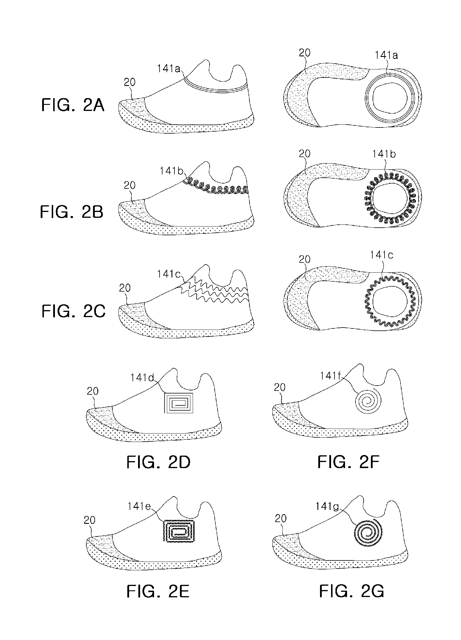
FIGS. 2A-2G illustrate various shapes of the transmission resonant coil unit 141 provided in the topline of the shoes 20. In FIG. 2A-2G, only the transmission resonant coil unit 141 provided in the topline of the shoes 20 is illustrated, but the reception resonant coil unit 142 provided in the cuffs of the trousers 10 may also be configured to correspond thereto.
As illustrated in FIGS. 2A-2C, the transmission resonant coil unit 141 may be provided in the topline of the shoes 20 to surround the ankle of the wearer. As illustrated in FIGS. 2D-2G, the transmission resonant coil unit 141 may have a planar shape provided on an inner or outer side of the shoes 20.
In detail, in the former case (FIGS. 2A-2C), the transmission resonant coil unit 141 may be wound in at least one of a spiral shape 141a (please refer to FIG. 2A), an up/down zigzag shape 141b (please refer to FIG. 2B), and a helical shape 141c (please refer to FIG. 2C) along a topline. In FIGS. 2A-2C, the left side shows side views and the right side shows plan views. Here, FIGS. 2B-2C may be designated to have an indented shape.
In the case of FIGS. 2A-2C, the user's ankle is positioned at a central portion of the transmission resonant coil unit 141, and here, a diameter of the reception resonant coil unit 142 may be greater than that of the transmission resonant coil unit 141. Since the transmission resonant coil unit 141 is positioned to be centered on the user's ankle, there is not much change in a shape and a position of the transmission resonant coil unit 141 in spite of a user's movement, maintaining predetermined transmission efficiency.
In particular, the case of FIG. 2A is useful when the topline of the shoes 20 and the cuffs of the trousers (10) have a conical shape, and the cases of FIGS. 2B-2C are advantageous in that a frequency resonance may be easily adjusted by adjusting a length of a coil even when diameters of the topline of the shoes 20 in which the transmission resonant coil unit 141 is installed and the cuffs of the trousers (1) are small.
In the cases of FIGS. 2A-2C, the reception resonant coil unit 142 may be provided in the cuffs of the trousers 10 and may be wound in at least one of the spiral shape, the up/down zigzag shape, or the helical shape along the circumference of the trousers (10) (not shown), the same shapes as those of FIGS. 2A-2C.
Meanwhile, in the cases of FIGS. 2D-2G, the transmission resonant coil unit 141 may have a planar shape provided on an inner or outer side of the shoes 20 and may be spirally wound in a quadrangular shape 141d and 141e (please refer to FIGS. 2D-2E) or in a circular shape 141f and 141g (please refer to FIGS. 2F-2G) a plurality of times or may additionally have an indented shape. Here, the indented shape refers to a shape in which the transmission resonant coil unit 141 is wound around in a zigzag manner up and down as illustrated in FIG. 2E or is wound in a helical shape along the circumference as illustrated in FIG. 2F.
In the cases of FIGS. 2D-2F), the transmission resonant coil unit 141 may be designed to have a diameter smaller than that of the cases of FIGS. 2A-2C), and a reduction in transmission efficiency that occurs due to contact with a human body may be minimized.
In particular, the cases of FIGS. 2D-2F are advantageous in that the transmission resonant coil unit 141 may have a size smaller than that of FIGS. 2A-2C) described above, regardless of shapes of the topline of the shoes 20 and the cuffs of the trousers 10. Also, the cases of FIGS. 2E-2G) are advantageous in that a resonant frequency may be easily adjusted by adjusting a length of a coil without having to increase a size of the transmission resonant coil unit 141.
Similarly, in the cases of FIGS. 2D-2G), the reception resonant coil unit 142 may be provided in a position corresponding to a position of the transmission resonant coil unit 141, on an inner or outer side of the trousers 10 and may have the same shape as those of FIGS. 2D-2G (not shown).
As described above, the resonant coil module 140 includes the transmission resonant coil unit 141 provided in the shoes 20 and the reception resonant coil unit 142 provided on the cuffs of the trousers 10, spaced apart from the transmission resonant coil unit 141 by a predetermined distance, and configured to be magnetically coupled to the transmission resonant coil unit 141, and energy harvested by the energy harvesting device 110 may be wirelessly transmitted to the charge control module 160.
The aforementioned transmission resonant coil unit 141 may include a primary coil having one winding (one turn) and a transmission resonant coil disposed to be spaced apart from the primary coil by a predetermined distance and having at least two windings, and the reception resonant coil unit 142 may include a reception resonant coil having at least two windings and a secondary coil disposed to be spaced apart from the reception resonant coil by a predetermined distance and having one winding (one turn).
The aforementioned transmission resonant coil unit 141 may be a conductive thread obtained by doubling and twisting a copper wire and thread and weaving the same in the shoes 20 in fabric form, and the reception resonating coil unit 142 may also be conductive thread obtained by doubling and twisting a copper wire and thread and weaving the same in the trousers 10 in fabric form.
Also, as illustrated in FIG. 1, the conductive thread 150 may be connected to the resonant coil module 140, specifically, to the reception resonant coil unit 142 and transmit energy wirelessly received from the transmission resonant coil unit 141 to the charge control module 160.
The aforementioned conductive thread 150 may also be a conductive thread obtained by doubling and twisting a copper wire and thread and weaving the same in the trousers 10 in fabric form.
Meanwhile, the charge control module 160 may be attached to the trousers 10 and control charging of a mobile terminal MT using energy harvested by the energy harvesting device 110.
The charge control module 160 will be described in detail with reference to FIG. 3.
As illustrated in FIG. 3, the charge control module 160 may include a controller 161, a sensing unit 162, and an LED 163. The controller 161 may charge the mobile terminal MT using energy transmitted in a wired manner through the conductive thread 150. The controller 161 may include an AC/DC converter, or the like, and a detailed description thereof will be omitted.
Meanwhile, the charge control module may further include the sensing unit 162.
The sensing unit 162, an element for sensing contact with a human body, may serve to sense capacitance based on contact with a finger 1 or a change in a resistance value due to contact with the finger 1. When a change in capacitance or a change in a resistance value is sensed, the sensing unit 162 may transmit the sensed change to the controller 161, and the controller 162 may start charging of the mobile terminal MT or stop ongoing charging accordingly. Meanwhile, the LED 163 for displaying a charging state of the mobile terminal MT may be further provided.
The conductive thread 150 and the charge control module 160 and the conductive thread 150 and the mobile terminal MT may be connected by connectors C. In FIG. 1, it is illustrated that the mobile terminal MT is positioned within a pocket 11 of the trousers 10, but the mobile terminal MT may also be connected from outside.
As described above, according to an exemplary embodiment of the present disclosure, since the energy harvesting device is provided in the shoes and energy generated by the harvesting device is wirelessly transmitted using the resonant coil module provided in the shoes and trousers, whereby the mobile terminal MT may be effectively charged using energy generated according to a movement of a human body.
Also, according to another exemplary embodiment of the present disclosure, since the resonant coil module uses a conductive thread obtained by doubling and twisting a copper wire and thread and weaving the same in the shoes or trousers in fabric form, discomfort that users may feel in charging the mobile terminal may be minimized.
FIG. 4 is a flow chart illustrating a method of charging a mobile terminal using an energy harvesting device according to an exemplary embodiment in the present disclosure. In order to clarify the present disclosure, a description regarding the same parts as those described above with reference to FIGS. 1 to 3 will be omitted.
As illustrated in FIGS. 1A to 4, first, the energy harvesting device 110 provided in the shoes 20 may generate energy generated by a movement of a human body in operation S401.
As mentioned above, the energy harvesting device 110 may be provided in the shoes 20 to generate energy generated by a movement of a human body and include at least one of a piezoelectric device converting pressure applied according to a movement of a human body into energy or a capacitive device converting static electricity generated according to a movement of a human body into energy, for example.
In addition, as mentioned above, the rectifying unit 120 may convert energy harvested by the energy harvesting device 110 into DC power, and the oscillation unit 130 may oscillate the DC power converted by the rectifying unit 120 to have the same frequency as the resonant frequency of the transmission resonant coil unit 141.
Thereafter, the resonant coil module 140 may wirelessly transmit energy harvested by the energy harvesting device 110 to the charge control module 160 in operation S402.
The resonant coil module 140 may include the transmission resonant coil unit 141 provided in the topline of the shoes 20 and the reception resonant coil unit 142 provided on the cuffs of the trousers 10, and various configurations thereof have been described with reference to FIGS. 2A-2G.
In addition, the aforementioned resonant coil module 140 may be a conductive thread obtained by doubling and twisting a copper wire and thread and weaving the same in the shoes 20 or trousers 10 in fabric form, as mentioned above.
Finally, the charge control module 160 attached to the trousers 10 may control charging the mobile terminal MT using energy harvested by the energy harvesting device 110 in operation S403.
In addition, when a change in capacitance or a change in a resistance value is sensed, the sensing unit 162 may transmit the same to the controller 161, and the controller 161 may start charging the mobile terminal MT or may stop ongoing charging accordingly, as mentioned above.
As set forth above, according to exemplary embodiments of the present disclosure, since the energy harvesting device is provided in the shoes and energy generated by the harvesting device is wirelessly transmitted using the resonant coil module provided in the shoes and trousers, whereby the mobile terminal MT may be effectively charged using energy generated according to a movement of a human body.
In addition, according to another exemplary embodiment of the present disclosure, since the resonant coil module uses a conductive thread obtained by doubling and twisting a copper wire and thread and weaving the same in the shoes or trousers in fabric form, discomfort that users may feel in charging the mobile terminal may be minimized.
While exemplary embodiments have been shown and described above, it will be apparent to those skilled in the art that modifications and variations could be made without departing from the scope of the present invention as defined by the appended claims.
* * * * *
D00000
D00001
D00002
D00003
D00004
XML
uspto.report is an independent third-party trademark research tool that is not affiliated, endorsed, or sponsored by the United States Patent and Trademark Office (USPTO) or any other governmental organization. The information provided by uspto.report is based on publicly available data at the time of writing and is intended for informational purposes only.
While we strive to provide accurate and up-to-date information, we do not guarantee the accuracy, completeness, reliability, or suitability of the information displayed on this site. The use of this site is at your own risk. Any reliance you place on such information is therefore strictly at your own risk.
All official trademark data, including owner information, should be verified by visiting the official USPTO website at www.uspto.gov. This site is not intended to replace professional legal advice and should not be used as a substitute for consulting with a legal professional who is knowledgeable about trademark law.