Zoom lens, projection display device, and imaging apparatus
Amano , et al.
U.S. patent number 10,324,278 [Application Number 15/687,594] was granted by the patent office on 2019-06-18 for zoom lens, projection display device, and imaging apparatus. This patent grant is currently assigned to FUJIFILM Corporation. The grantee listed for this patent is FUJIFILM Corporation. Invention is credited to Masaru Amano, Kazuki Inoue, Akiko Nagahara, Yukiko Nagatoshi.


View All Diagrams
| United States Patent | 10,324,278 |
| Amano , et al. | June 18, 2019 |
Zoom lens, projection display device, and imaging apparatus
Abstract
A zoom lens forms an intermediate image at a position conjugate to a reduction side imaging plane and forms the intermediate image again on a magnification side imaging plane. The zoom lens includes a plurality of lens groups including at least two movable lens groups, which move by changing spacings between the groups adjacent to each other in a direction of an optical axis during zooming, at a position closer to the reduction side than the intermediate image. Among the plurality of lens groups, a final lens group closest to the reduction side has a positive refractive power, and remains stationary with respect to the reduction side imaging plane during zooming. The zoom lens satisfies predetermined conditional expressions (1) and (2).
| Inventors: | Amano; Masaru (Saitama, JP), Nagahara; Akiko (Saitama, JP), Nagatoshi; Yukiko (Saitama, JP), Inoue; Kazuki (Saitama, JP) | ||||||||||
|---|---|---|---|---|---|---|---|---|---|---|---|
| Applicant: |
|
||||||||||
| Assignee: | FUJIFILM Corporation (Tokyo,
JP) |
||||||||||
| Family ID: | 61242314 | ||||||||||
| Appl. No.: | 15/687,594 | ||||||||||
| Filed: | August 28, 2017 |
Prior Publication Data
| Document Identifier | Publication Date | |
|---|---|---|
| US 20180059385 A1 | Mar 1, 2018 | |
Foreign Application Priority Data
| Aug 30, 2016 [JP] | 2016-168096 | |||
| Current U.S. Class: | 1/1 |
| Current CPC Class: | G02B 15/173 (20130101); G02B 15/14 (20130101) |
| Current International Class: | G02B 15/14 (20060101); G02B 15/173 (20060101) |
References Cited [Referenced By]
U.S. Patent Documents
| 2014/0362452 | December 2014 | Obama |
| 2015-152890 | Aug 2015 | JP | |||
Assistant Examiner: Sumlar; Journey F
Attorney, Agent or Firm: Studebaker & Brackett PC
Claims
What is claimed is:
1. A zoom lens that forms an intermediate image at a position conjugate to a reduction side imaging plane and forms the intermediate image again on a magnification side imaging plane, the zoom lens comprising a plurality of lens groups including at least two movable lens groups, which move by changing spacings between the groups adjacent to each other in a direction of an optical axis during zooming, at a position closer to the reduction side than the intermediate image, wherein among the plurality of lens groups, a final lens group closest to the reduction side has a positive refractive power, and remains stationary with respect to the reduction side imaging plane during zooming, and wherein the following conditional expressions (1) and (2) are satisfied, 6.8<fM/|fw| (1), and 0<Ymax/|exPw|<0.1 (2), where fM is a focal length of the final lens group, fw is a focal length of the whole system at a wide-angle end, Ymax is an effective image circle radius on the reduction side, and exPw is a distance on the optical axis from the reduction side imaging plane to a paraxial exit pupil position at the wide-angle end in a case where the reduction side is set as an exit side.
2. The zoom lens according to claim 1, comprising four or five lens groups as a whole, wherein a lens group closest to the magnification side and the final lens group closest to the reduction side remain stationary with respect to the reduction side imaging plane during zooming, and wherein among lens groups between the lens group closest to the magnification side and the final lens group closest to the reduction side, at least two lens groups move by changing spacings between the groups adjacent to each other in the direction of the optical axis during zooming.
3. The zoom lens according to claim 1, wherein the following conditional expression (3) is satisfied, 0<|fw|/fA<0.145 (3), where fA is a focal length of a movable lens group closest to the reduction side among the plurality of movable lens groups.
4. The zoom lens according to claim 3, wherein the following conditional expression (3-1) is satisfied. 0<|fw|/fA<0.14 (3-1).
5. The zoom lens according to claim 1, wherein the following conditional expression (4) is satisfied, 0.01<|fw|/fB<0.2 (4), where fB is a focal length of a second movable lens group from the reduction side among the plurality of movable lens groups.
6. The zoom lens according to claim 5, wherein the following conditional expression (4-1) is satisfied. 0.03<|fw|/fB<0.16 (4-1).
7. The zoom lens according to claim 1, wherein the following conditional expression (5) is satisfied, 2<Bfw/|fw| (5), where Bfw is a back focal length of the whole system as an air conversion length at the wide-angle end.
8. The zoom lens according to claim 7, wherein the following conditional expression (5-1) is satisfied. 3<Bfw/|fw|<11 (5-1).
9. The zoom lens according to claim 1, wherein the final lens group is formed as one single lens.
10. The zoom lens according to claim 1, wherein the following conditional expression (1-1) is satisfied. 7<fM/|fw|<20 (1-1).
11. The zoom lens according to claim 1, wherein the following conditional expression (2-1) is satisfied. 0<Ymax/|exPw|<0.07 (2-1).
12. A projection display device comprising: a light source; a light valve into which light originating from the light source is incident; and the zoom lens according to claim 1, the zoom lens projecting an optical image, which is formed by light modulated through the light valve, onto a screen.
13. An imaging apparatus comprising the zoom lens according to claim 1.
Description
CROSS REFERENCE TO RELATED APPLICATIONS
The present application claims priority under 35 U.S.C. .sctn. 119 to Japanese Patent Application No. 2016-168096 filed on Aug. 30, 2016. The above application is hereby expressly incorporated by reference, in its entirety, into the present application.
BACKGROUND OF THE INVENTION
1. Field of the Invention
The present invention relates to a zoom lens forming an intermediate image, a projection display device comprising the zoom lens, and an imaging apparatus comprising the zoom lens.
2. Description of the Related Art
In the past, projection display devices, each of which uses a light valve such as a liquid crystal display element or a Digital Micromirror Device (DMD.RTM.) display element, have come into widespread use. In particular, some widely used devices adopt a configuration in which three light valves are used, illumination light beams with three primary colors of red, green, and blue respectively correspond to the light valves, synthesizes the light beams, which are modulated through the respective light valves, through a prism or the like, and displays an image onto a screen through a zoom lens.
In such a zoom lens used in a type of the projection display device that synthesizes the light beams modulated through the three light valves through a color synthesis optical system and projects the light beams, as described above, in order for a prism or the like for performing color synthesis to be disposed therein and in order to avoid a thermal problem, a long back focal length is necessary. Further, since spectral characteristics of the color synthesizing prism change depending on an angle of incident light, it is necessary for the projection lens to have the characteristic that the entrance pupil is at a sufficiently far position in a case where the reduction side is set as the incident side, that is, to be telecentric on the reduction side.
It has become necessary for such a type of the zoom lens to perform favorable aberration correction appropriate for the resolutions of light valves. Further, from the viewpoint of installability, in order to cope with the demands to have a high zoom ratio function and to perform projection onto a large screen at a short distance, it is necessary for a zoom lens to have a wider angle of view.
A zoom lens, which forms an intermediate image at a position conjugate to the reduction side imaging plane and forms the intermediate image again on the magnification side imaging plane, has been proposed so as to cope with such demands (for example, JP2015-152890A).
SUMMARY OF THE INVENTION
In a normal zoom lens of a system which does not form an intermediate image, in a case where an increase in angle of view is intended to be achieved by shortening a focal length thereof, the size of the magnification side lens inevitably becomes excessively large. However, in a zoom lens of a system which forms an intermediate image as described above, it is possible to shorten a back focal length of the lens system closer to the magnification side than the intermediate image. Therefore, it is possible to decrease a magnification side lens diameter of the lens system closer to the magnification side than the intermediate image, and this configuration is appropriate for achieving an increase in angle of view by shortening a focal length thereof. However, fluctuation in aberrations becomes large during zooming, and thus a problem arises in that it is difficult to keep optical performance high in the entire zooming range. In the lens system described in JP2015-152890A, a problem also arises in that fluctuation in aberrations is large.
The present invention has been made in consideration of the above-mentioned situation, and its object is to provide a zoom lens of a system that forms an intermediate image and has high performance by satisfactorily suppressing fluctuation in aberrations during zooming while achieving a wide angle, a projection display device comprising the zoom lens, and an imaging apparatus comprising the zoom lens.
A zoom lens of the present invention forms an intermediate image at a position conjugate to a reduction side imaging plane and forms the intermediate image again on a magnification side imaging plane. The zoom lens comprises a plurality of lens groups including at least two movable lens groups, which move by changing spacings between the groups adjacent to each other in a direction of an optical axis during zooming, at a position closer to the reduction side than the intermediate image. Among the plurality of lens groups, a final lens group closest to the reduction side has a positive refractive power, and remains stationary with respect to the reduction side imaging plane during zooming. The zoom lens satisfies the following conditional expressions (1) and (2). 6.8<fM/|fw| (1) 0<Ymax/|exPw|<0.1 (2)
Here, fM is a focal length of the final lens group,
fw is a focal length of the whole system at a wide-angle end,
Ymax is an effective image circle radius on the reduction side, and
exPw is a distance on the optical axis from the reduction side imaging plane to a paraxial exit pupil position at the wide-angle end in a case where the reduction side is set as an exit side.
Here, "comprises a plurality of lens groups including at least two movable lens groups, which move by changing spacings between the groups adjacent to each other in a direction of an optical axis during zooming, at a position closer to the reduction side than the intermediate image" the term means that the at least two movable lens groups other than the lens group including the intermediate image are provided at the position closer to the reduction side than the lens group including the intermediate image in a case where the intermediate image is formed in the lens group.
It is preferable that the zoom lens of the present invention satisfies the following conditional expression (1-1) and/or (2-1). 7<fM/|fw<20 (1-1) 0<Ymax/|exPw|<0.07 (2-1)
The zoom lens may comprise four or five lens groups as a whole. A lens group closest to the magnification side and the final lens group closest to the reduction side may remain stationary with respect to the reduction side imaging plane during zooming. Among lens groups between the lens group closest to the magnification side and the final lens group closest to the reduction side, at least two lens groups may move by changing spacings between the groups adjacent to each other in the direction of the optical axis during zooming.
It is preferable that the zoom lens satisfies the following conditional expression (3), and it is more preferable that the zoom lens satisfies the following conditional expression (3-1). 0<|fw|/fA<0.145 (3) 0<|fw|/fA<0.14 (3-1)
Here, fw is a focal length of the whole system at the wide-angle end, and
fA is a focal length of a movable lens group closest to the reduction side among the plurality of movable lens groups.
It is preferable that the zoom lens satisfies the following conditional expression (4), and it is more preferable that the zoom lens satisfies the following conditional expression (4-1). 0.01<|fw|/fB<0.2 (4) 0.03<|fw|/fB<0.16 (4-1)
Here, fw is a focal length of the whole system at the wide-angle end, and
fB is a focal length of a second movable lens group from the reduction side among the plurality of movable lens groups.
It is preferable that the zoom lens satisfies the following conditional expression (5), and it is more preferable that the zoom lens satisfies the following conditional expression (5-1). 2<Bfw/|fw| (5) 3<Bfw/|fw|<11 (5-1)
Here, Bfw is a back focal length of the whole system as an air conversion length at the wide-angle end, and
fw is a focal length of the whole system at the wide-angle end.
It is preferable that the final lens group is formed as one single lens.
A projection display device of the present invention comprises: a light source; a light valve into which light originating from the light source is incident; and the zoom lens of the present invention, the zoom lens projecting an optical image, which is formed by light modulated through the light valve, onto a screen.
An imaging apparatus of the present invention comprises the above-mentioned zoom lens of the present invention.
It should be noted that the "magnification side" means a projected side (screen side). Even in a case where projection is performed in a reduced manner, for convenience, the screen side is referred to as the magnification side. On the other hand, the "reduction side" means an image display element side (light valve side). Even in a case where projection is performed in a reduced manner, for convenience, the light valve side is referred to as the reduction side.
Further, the "comprises . . . " means that the zoom lens may include not only the above-mentioned elements but also lenses substantially having no powers, optical elements, which are not lenses, such as a mirror having no power, a stop, a mask, a cover glass, a filter, and the like.
Further, the "lens group" is not necessarily formed of a plurality of lenses, but may be formed of only one lens.
Further, regarding the "back focal length", the following assumption is considered: the magnification side and the reduction side respectively correspond to the object side and the image side of a general imaging lens, and the magnification side and the reduction side are respectively referred to as the front side and the back side.
According to the present invention, a zoom lens forms an intermediate image at a position conjugate to a reduction side imaging plane and forms the intermediate image again on a magnification side imaging plane. The zoom lens comprises the plurality of lens groups including at least two movable lens groups, which move by changing spacings between the groups adjacent to each other in the direction of the optical axis during zooming, at the position closer to the reduction side than the intermediate image. Among the plurality of lens groups, the final lens group closest to the reduction side has a positive refractive power, and remains stationary with respect to the reduction side imaging plane during zooming. The zoom lens satisfies the following conditional expressions (1) and (2). Therefore, it is possible to provide a zoom lens that has high performance by satisfactorily suppressing fluctuation in aberrations during zooming while achieving a wide angle, a projection display device comprising the zoom lens, and an imaging apparatus comprising the zoom lens. 6.8<fM/|fw| (1) 0<Ymax/|exPw|<0.1 (2)
BRIEF DESCRIPTION OF THE DRAWINGS
FIG. 1 is a cross-sectional view illustrating a configuration of a zoom lens (common to Example 1) according to an embodiment of the present invention.
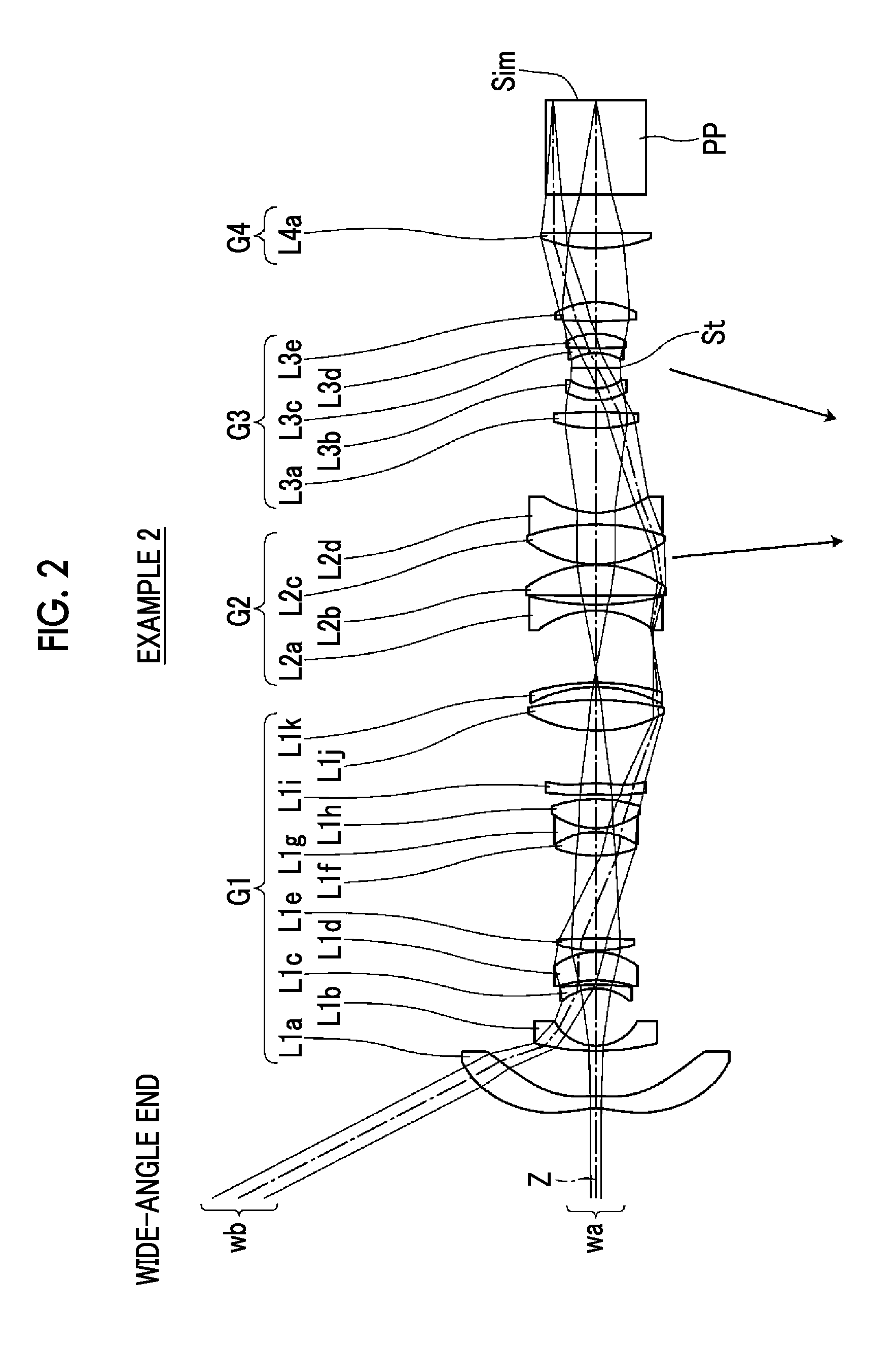
FIG. 2 is a cross-sectional view illustrating a configuration of a zoom lens of Example 2 of the present invention.
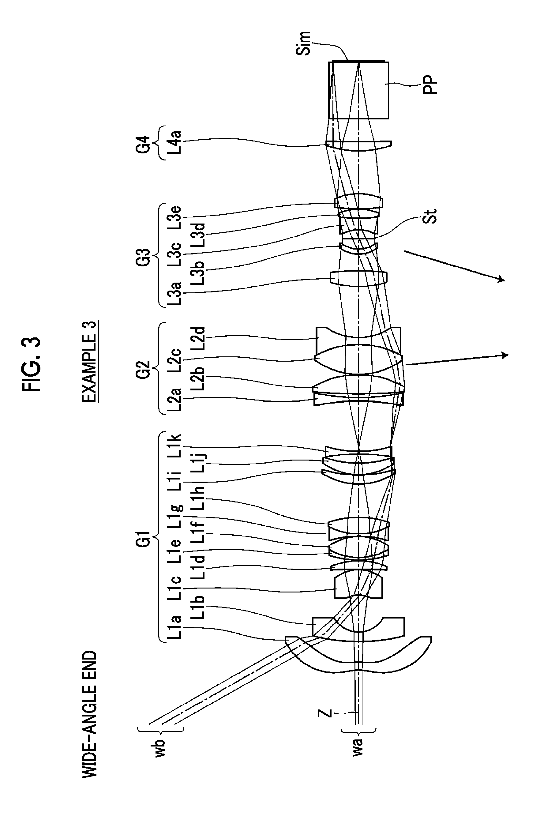
FIG. 3 is a cross-sectional view illustrating a configuration of a zoom lens of Example 3 of the present invention.
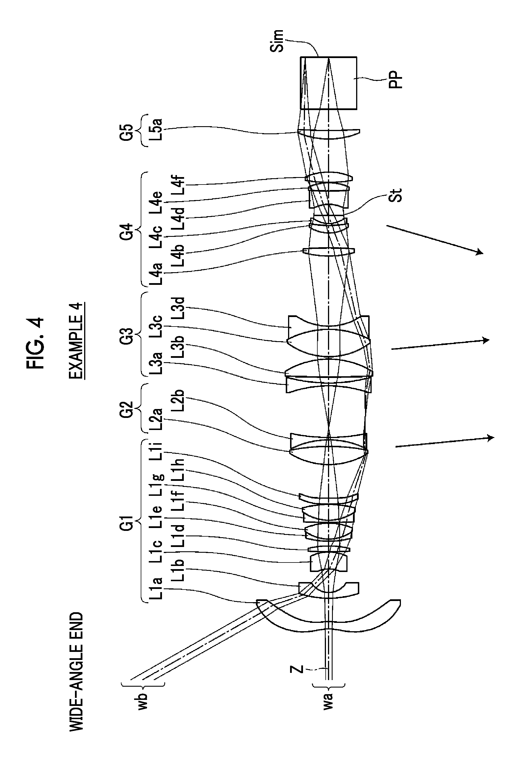
FIG. 4 is a cross-sectional view illustrating a configuration of a zoom lens of Example 4 of the present invention.
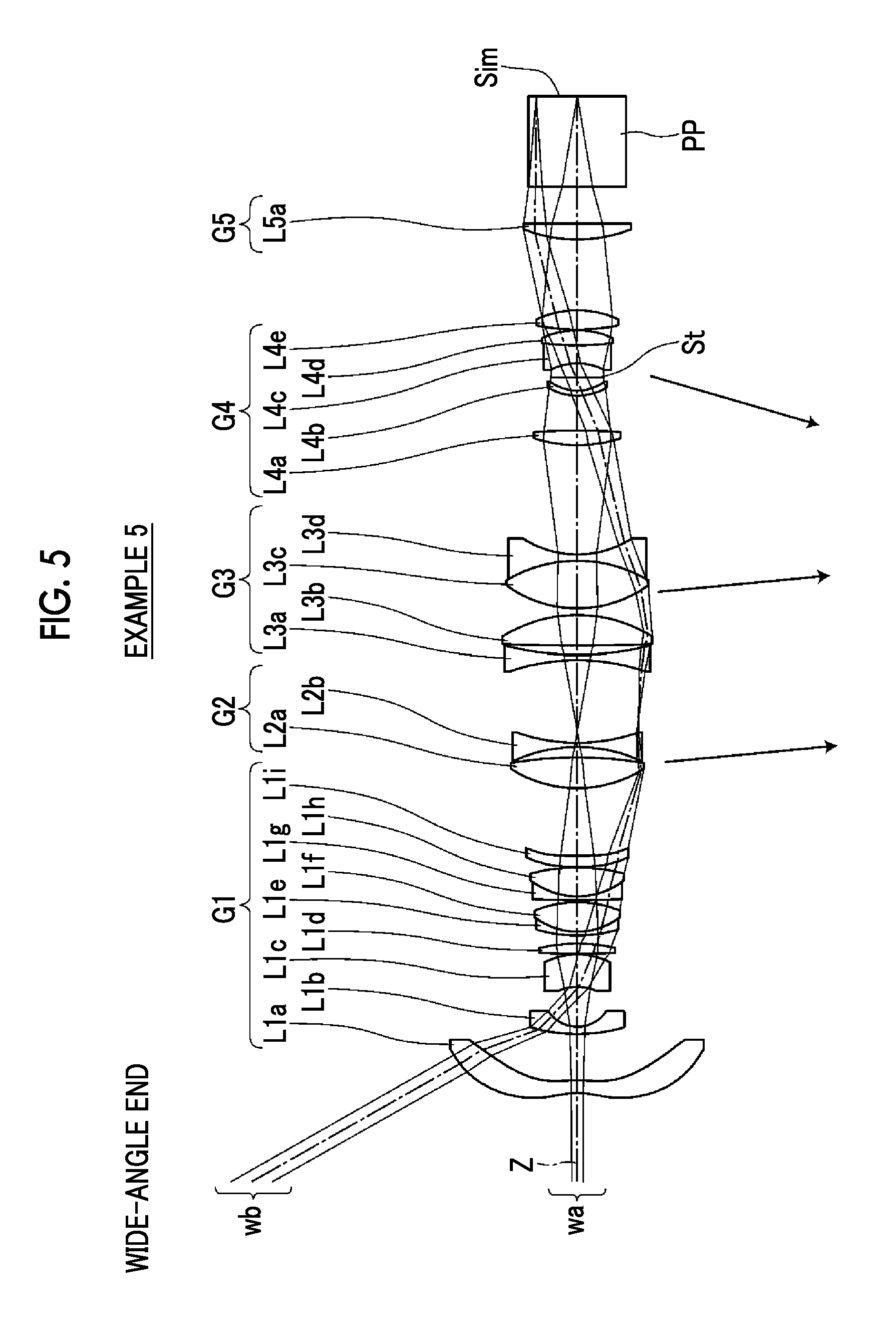
FIG. 5 is a cross-sectional view illustrating a configuration of a zoom lens of Example 5 of the present invention.
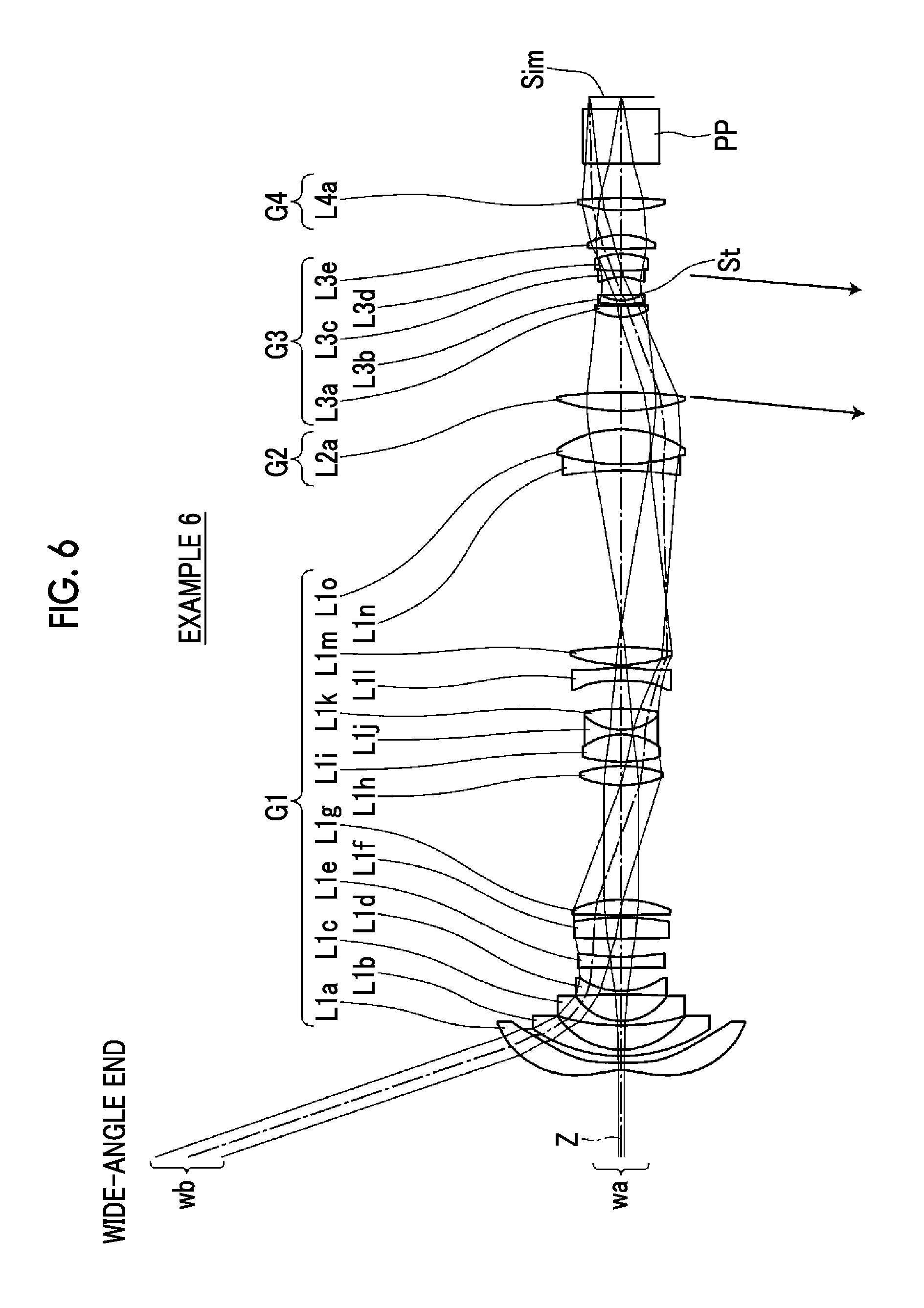
FIG. 6 is a cross-sectional view illustrating a configuration of a zoom lens of Example 6 of the present invention.
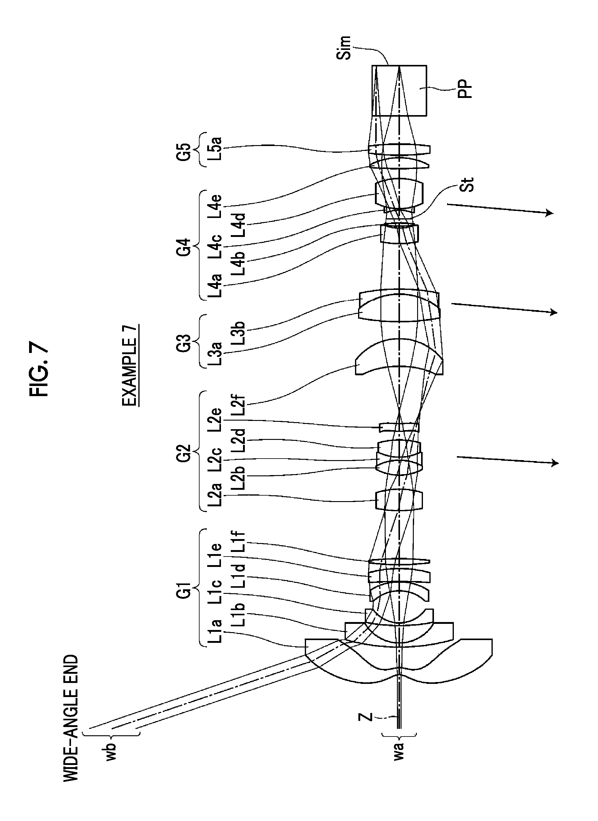
FIG. 7 is a cross-sectional view illustrating a configuration of a zoom lens of Example 7 of the present invention.
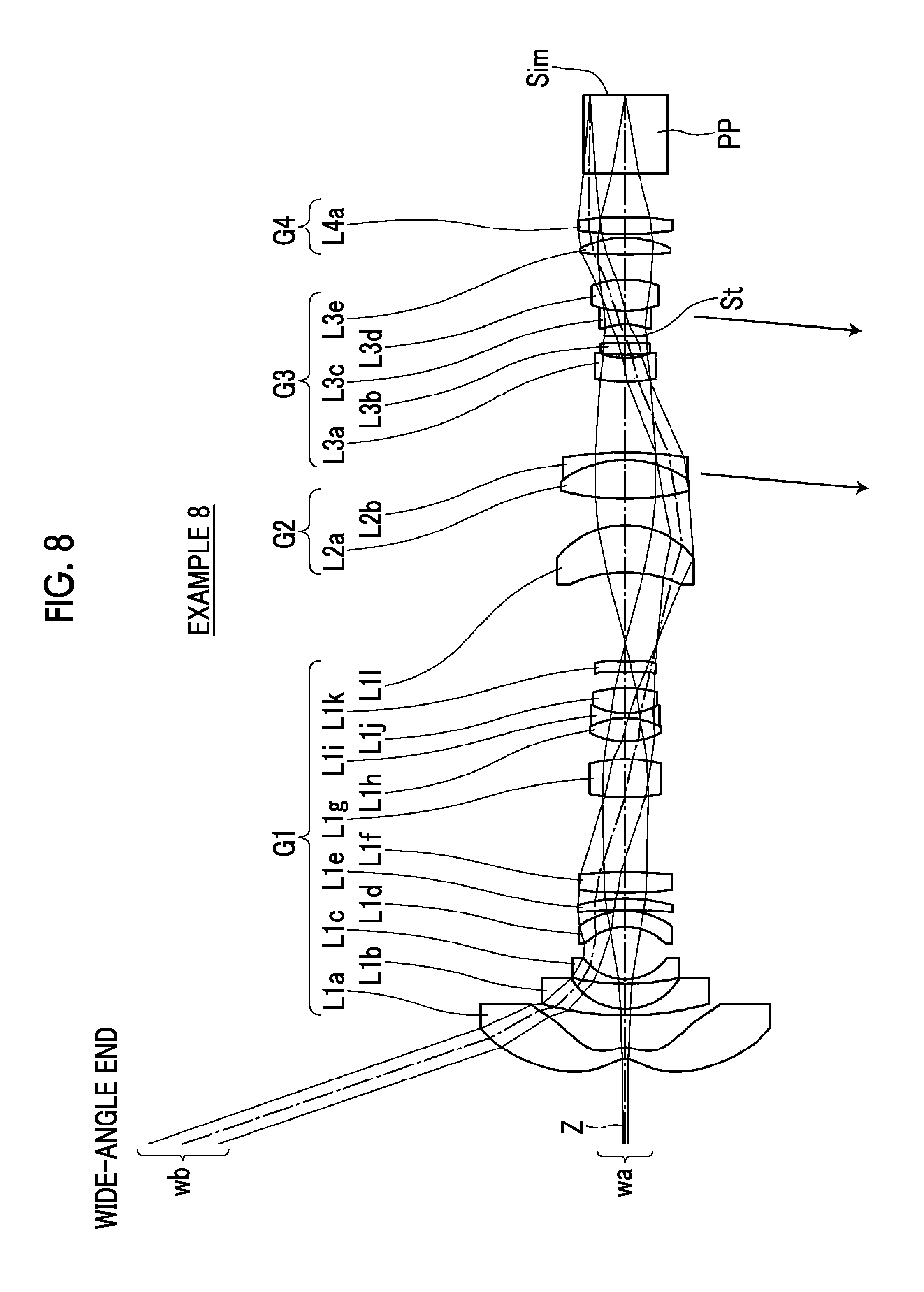
FIG. 8 is a cross-sectional view illustrating a configuration of a zoom lens of Example 8 of the present invention.
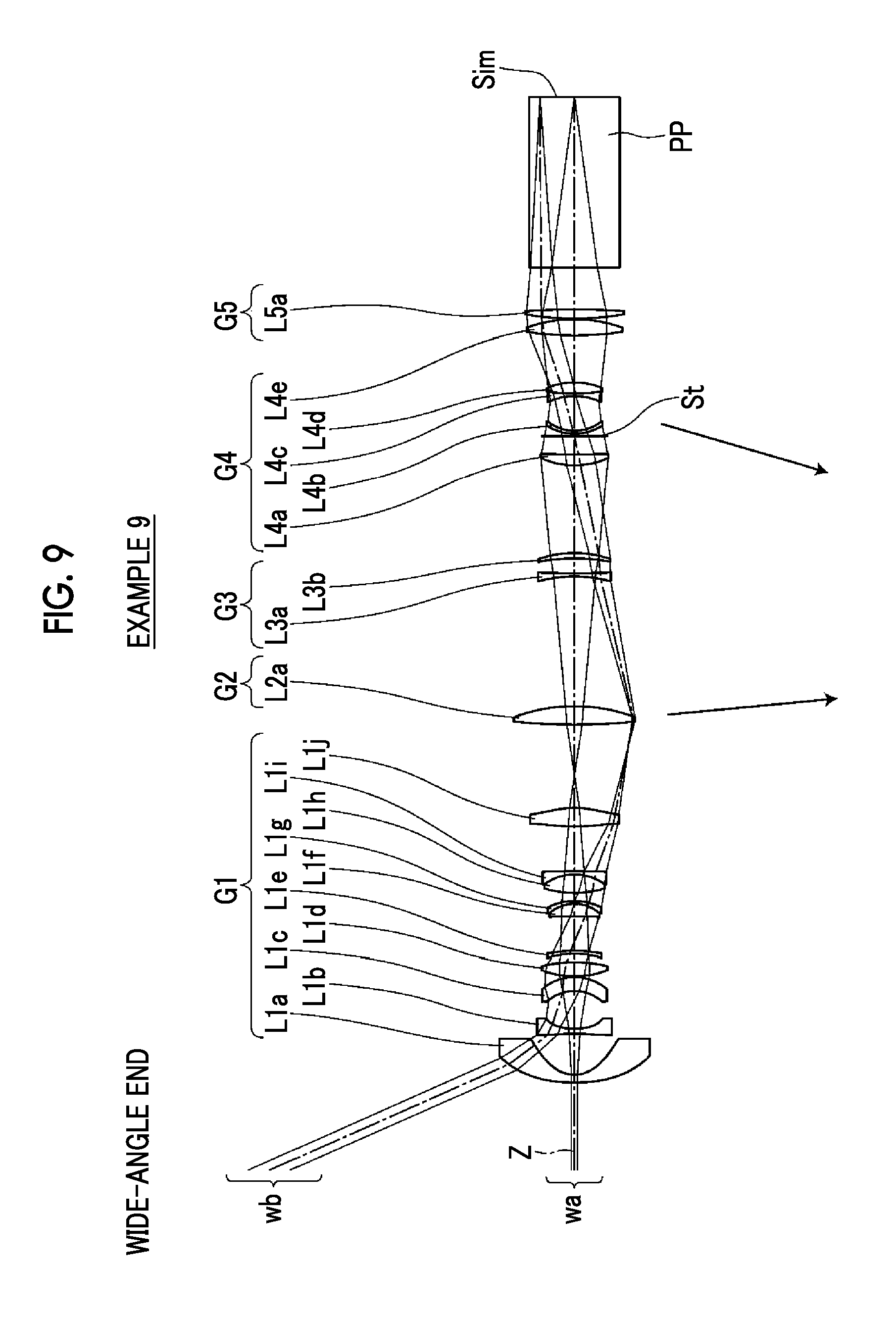
FIG. 9 is a cross-sectional view illustrating a configuration of a zoom lens of Example 9 of the present invention.
FIG. 10 is a cross-sectional view illustrating a configuration of a zoom lens of Example 10 of the present invention.
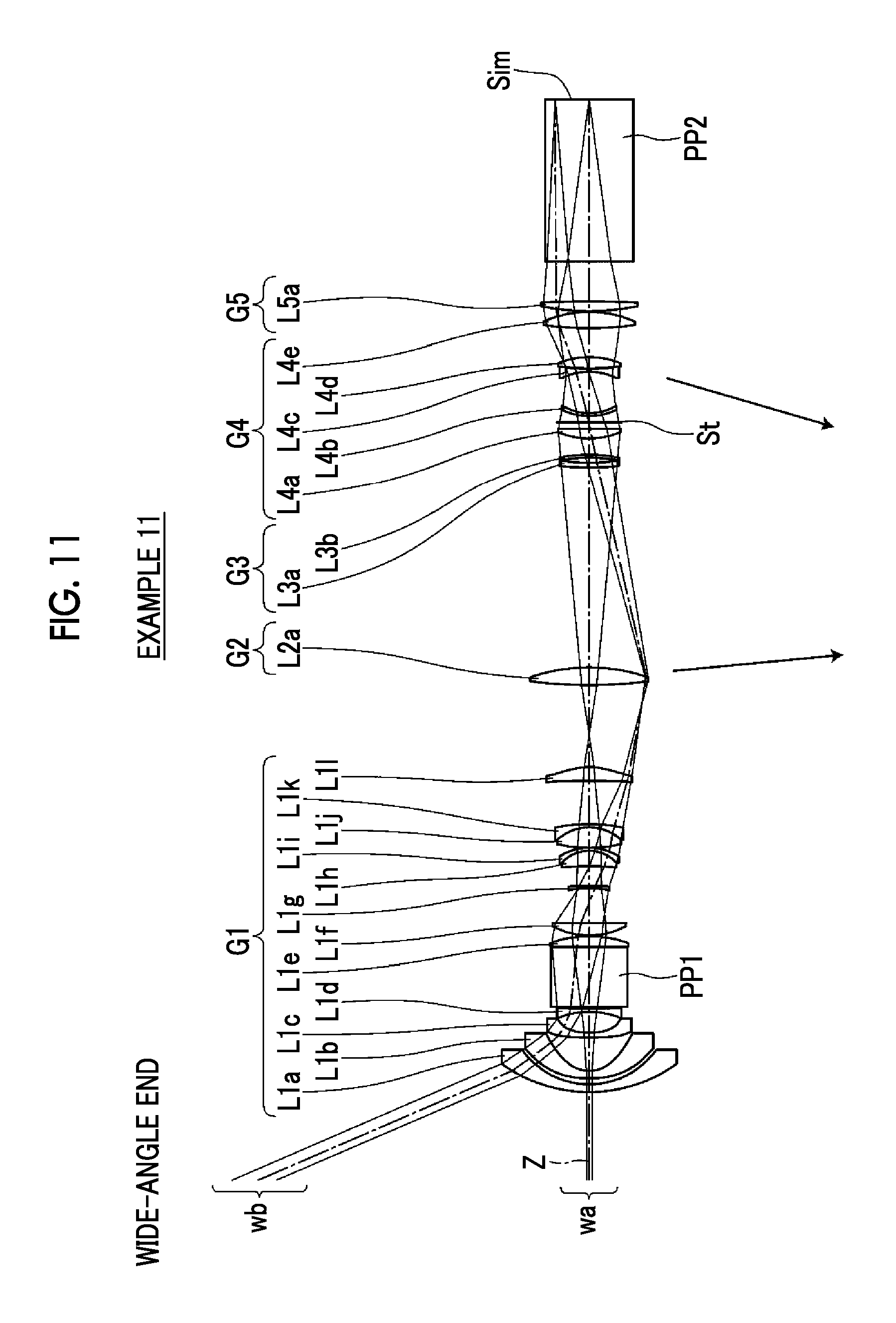
FIG. 11 is a cross-sectional view illustrating a configuration of a zoom lens of Example 11 of the present invention.
FIG. 12 is a diagram of aberrations of the zoom lens of Example 1 of the present invention.
FIG. 13 is a diagram of aberrations of the zoom lens of Example 2 of the present invention.
FIG. 14 is a diagram of aberrations of the zoom lens of Example 3 of the present invention.
FIG. 15 is a diagram of aberrations of the zoom lens of Example 4 of the present invention.
FIG. 16 is a diagram of aberrations of the zoom lens of Example 5 of the present invention.
FIG. 17 is a diagram of aberrations of the zoom lens of Example 6 of the present invention.
FIG. 18 is a diagram of aberrations of the zoom lens of Example 7 of the present invention.
FIG. 19 is a diagram of aberrations of the zoom lens of Example 8 of the present invention.
FIG. 20 is a diagram of aberrations of the zoom lens of Example 9 of the present invention.
FIG. 21 is a diagram of aberrations of the zoom lens of Example 10 of the present invention.
FIG. 22 is a diagram of aberrations of the zoom lens of Example 11 of the present invention.
FIG. 23 is a schematic configuration diagram of a projection display device according to an embodiment of the present invention.
FIG. 24 is a schematic configuration diagram of a projection display device according to another embodiment of the present invention.
FIG. 25 is a schematic configuration diagram of a projection display device according to still another embodiment of the present invention.
FIG. 26 is a perspective view of the front side of an imaging apparatus according to an embodiment of the present invention.
FIG. 27 is a perspective view of the rear side of the imaging apparatus shown in FIG. 26.
DESCRIPTION OF THE PREFERRED EMBODIMENTS
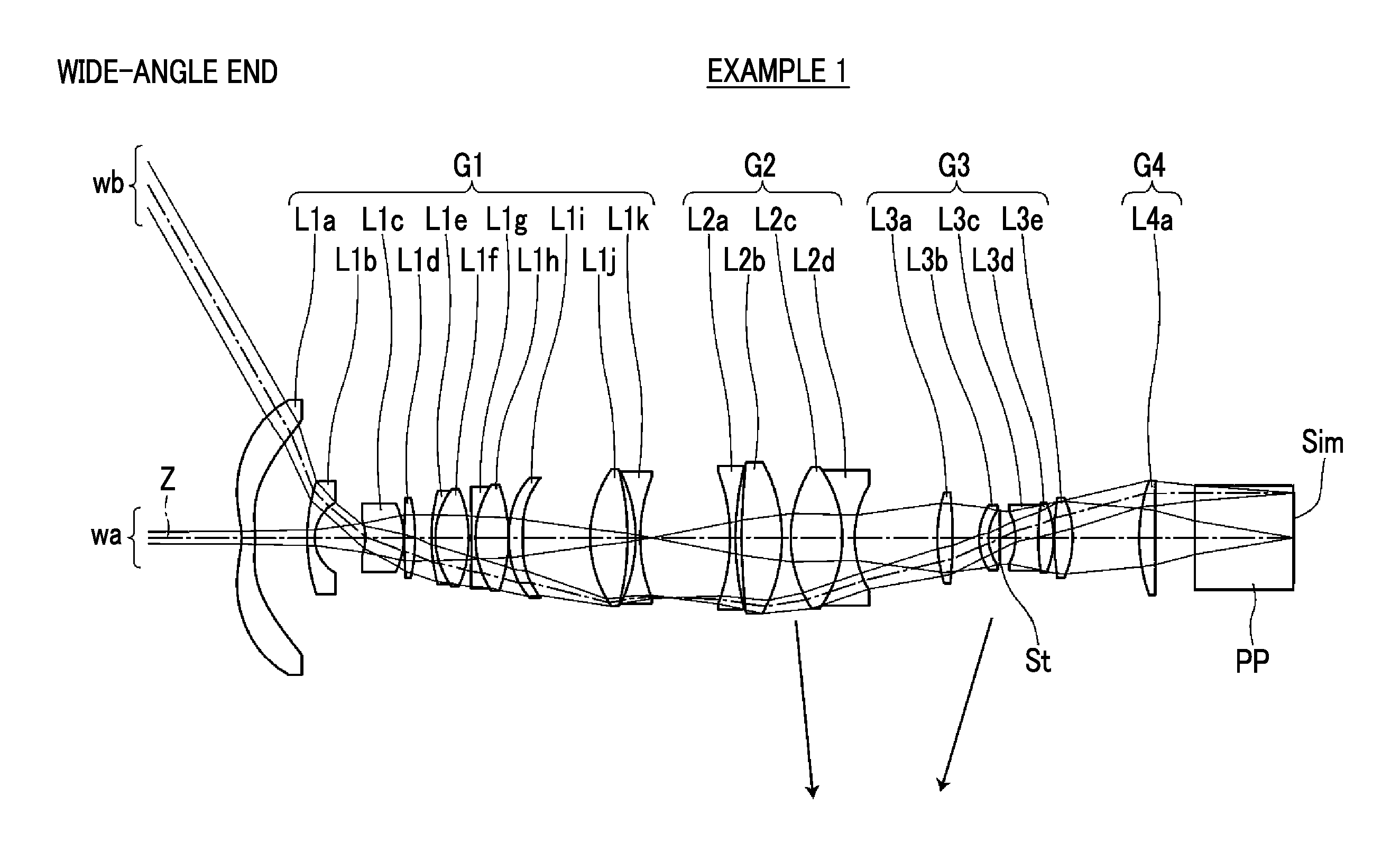
Hereinafter, embodiments of the present invention will be described with reference to drawings. FIG. 1 is a cross-sectional view illustrating a configuration of a zoom lens according to an embodiment of the present invention. The exemplary configuration shown in FIG. 1 is the same as the configuration of the zoom lens of Examples 1 to be described later. FIG. 1 shows a state at the wide-angle end, where an image display surface Sim side is the reduction side, a lens L1a side of the first lens group G1 is a magnification side, and an aperture stop St shown in the drawing does not necessarily show its real size and shape, but show a position on an optical axis Z. Further, in FIG. 1, on-axis rays wa and rays with a maximum angle of view wb are also shown together.
This zoom lens is, for example, mounted on a projection display device, and can be used to project image information displayed on the light valve onto the screen. In FIG. 1, assuming that the zoom lens is mounted on the projection display device, an optical member PP such as a filter or a prism used in a color synthesizing section or an illumination light separating section, and an image display surface Sim of a light valve positioned on a reduction side surface of the optical member PP are also shown. In the projection display device, rays, which are made to have image information through the image display surface Sim on the image display element, are incident into the zoom lens through the optical member PP, and are transmitted onto a screen, which is not shown in the drawing, through the zoom lens.
As shown in FIG. 1, the zoom lens of the present embodiment forms an intermediate image at a position conjugate to a reduction side imaging plane (image display surface Sim) and forms the intermediate image again on a magnification side imaging plane. The zoom lens includes a plurality of lens groups including at least two movable lens groups, which move by changing spacings between the groups adjacent to each other in a direction of an optical axis during zooming, at a position closer to the reduction side than the intermediate image. Among the plurality of lens groups, a final lens group closest to the reduction side has a positive refractive power, and remains stationary with respect to the reduction side imaging plane during zooming.
In the example shown in FIG. 1, the zoom lens includes, in order from the magnification side, a first lens group G1, a second lens group G2, a third lens group G3, and a fourth lens group G4. An intermediate image is formed between the first lens group G1 and the second lens group G2. The first lens group G1 and the fourth lens group G4 remain stationary with respect to the reduction side imaging plane (image display surface Sim) during zooming. The second lens group G2 and the third lens group G3 are configured to move by changing spacings of the groups adjacent to each other in the direction of the optical axis during zooming. That is, the second lens group G2 and the third lens group G3 correspond to the movable lens groups, and the fourth lens group G4 corresponds to the final lens group.
In a normal zoom lens of a system which does not form an intermediate image, in a case where an increase in angle of view is intended to be achieved by shortening a focal length thereof, the size of the magnification side lens inevitably becomes excessively large. However, in a manner similar to that of the present embodiment, in a zoom lens of a system which forms an intermediate image, it is possible to shorten a back focal length of the lens system (in the example shown in FIG. 1, the first lens group G1) closer to the magnification side than the intermediate image. In addition, it is possible to decrease a magnification side lens diameter, and this configuration is appropriate for achieving an increase in angle of view by shortening a focal length thereof.
Further, zooming is performed by moving a lens system closer to the reduction side than the intermediate image. As for the zooming operation, change in relay magnification of the lens system closer to the reduction side than the intermediate image corresponds to change in size of the intermediate image, and thus it is possible to achieve an optically simple configuration.
Further, the final lens group, which remains stationary with respect to the reduction side imaging plane during zooming and has a positive refractive power, is disposed to be closest to the reduction side. Thereby, it is possible to reduce fluctuation in aberrations during zooming while keeping the zoom lens telecentric.
Further, the zoom lens is configured to satisfy the following conditional expressions (1) and (2). 6.8<fM/|fw| (1) 0<Ymax/|exPw|<0.1 (2)
Here, fM is a focal length of the final lens group,
fw is a focal length of the whole system at the wide-angle end,
Ymax is an effective image circle radius on the reduction side, and
exPw is a distance on the optical axis from the reduction side imaging plane to a paraxial exit pupil position at the wide-angle end in a case where the reduction side is set as an exit side.
The conditional expression (1) is a conditional expression for satisfactorily correcting fluctuation in aberrations during zooming while keeping the zoom lens telecentric. By not allowing the result of the conditional expressions (1) to be equal to or less than the lower limit, it is possible to prevent the power of the final lens group from becoming excessively strong. Thus, by minimizing an amount of occurrence of lateral chromatic aberration in the final lens group, it is possible to easily correct lateral chromatic aberration in other groups. By not allowing the result of the conditional expressions (1) to be equal to or greater than the upper limit, it is possible to prevent the power of the final lens group from becoming excessively weak. Thus, it becomes easy to make the zoom lens telecentric on the reduction side.
The conditional expression (2) is also a conditional expression for satisfactorily correcting fluctuation in aberrations during zooming while keeping the zoom lens telecentric in the same manner. By satisfying the conditional expression (2), it becomes easy to ensure telecentricity while obtaining a size of a desired image circle.
In addition, in a case where the following conditional expression (1-1) and/or (2-1) is satisfied, it is possible to obtain more favorable characteristics. 7<fM/|fw|<20 (1-1) 0<Ymax/|exPw|<0.07 (2-1)
The zoom lens of the present invention may comprise four or five lens groups as a whole. A lens group closest to the magnification side and the final lens group closest to the reduction side may remain stationary with respect to the reduction side imaging plane during zooming. Among lens groups between the lens group closest to the magnification side and the final lens group closest to the reduction side, at least two lens groups may move by changing spacings between the groups adjacent to each other in the direction of the optical axis during zooming.
As described above, by adopting a configuration using at most five lens groups, it is possible to simplify a configuration of the entire zoom lens. Further, in a case where the lens group closest to the magnification side is intended to move during zooming, mechanical parts for the zooming operation are increased in size and elongated, and this leads to an increase in costs. Therefore, in addition to the final lens group, the lens group closest to the magnification side is also set to be stationary during zooming, whereby it is possible to solve such a problem.
It is preferable that the zoom lens satisfies the following conditional expression (3). By not allowing the result of the conditional expression (3) to be equal to or less than the lower limit, among the plurality of movable lens groups, the power of the movable lens group closest to the reduction side can be prevented from becoming excessively weak. Thus, an amount of movement for ensuring a desired zoom ratio is minimized, and this contributes to reduction in lens total length. By not allowing the result of the conditional expression (3) to be equal to or greater than the upper limit, among the plurality of movable lens groups, the power of the movable lens group closest to the reduction side can be prevented from becoming excessively strong. Thus, it is possible to suppress fluctuation in longitudinal chromatic aberration and spherical aberration during zooming. In addition, in a case where the following conditional expression (3-1) is satisfied, it is possible to obtain more favorable characteristics. 0<|fw|/fA<0.145 (3) 0<|fw|/fA<0.14 (3-1)
Here, fw is a focal length of the whole system at the wide-angle end, and
fA is a focal length of a movable lens group closest to the reduction side among the plurality of movable lens groups.
It is preferable that the zoom lens satisfies the following conditional expression (4). By not allowing the result of the conditional expression (4) to be equal to or less than the lower limit, among the plurality of movable lens groups, the power of the second movable lens group from the reduction side can be prevented from becoming excessively weak. Thus, it becomes easy to ensure the desired zoom ratio, and this contributes to reduction in lens diameter of the movable lens group. By not allowing the result of the conditional expression (4) to be equal to or greater than the upper limit, among the plurality of movable lens groups, the power of the second movable lens group from the reduction side can be prevented from becoming excessively strong. Thus, it is possible to easily correct astigmatism during zooming. In addition, in a case where the following conditional expression (4-1) is satisfied, it is possible to obtain more favorable characteristics. 0.01<|fw|/fB<0.2 (4) 0.03<|fw|/fB<0.16 (4-1)
Here, fw is a focal length of the whole system at the wide-angle end, and
fB is a focal length of a second movable lens group from the reduction side among the plurality of movable lens groups.
It is preferable that the zoom lens satisfies the following conditional expression (5). By not allowing the result of the conditional expression (5) to be equal to or less than the lower limit, it is possible to prevent the back focal length from being excessively shortened. Thus, it becomes easy to arrange the color synthesizing prism and the like. In addition, in a case where the following conditional expression (5-1) is satisfied, it is possible to obtain more favorable characteristics. By not allowing the result of the conditional expression (5-1) to be equal to or greater than the upper limit, it is possible to prevent the back focal length from becoming excessively large and the lens diameter from becoming large. Thus, it is possible to suppress an increase in number of lenses and an increase in costs of materials. 2<Bfw/|fw| (5) 3<Bfw/|fw|<11 (5-1)
Here, Bfw is a back focal length of the whole system as an air conversion length at the wide-angle end, and
fw is a focal length of the whole system at the wide-angle end.
It is preferable that the final lens group is formed as one single lens. With such a configuration, a configuration using the minimum number of lenses required for the lens configuration is made. As a result, this leads to reduction in costs.
Next, numerical examples of the zoom lens of the present invention will be described. First, a zoom lens of Example 1 will be described. FIG. 1 is a cross-sectional diagram illustrating a configuration of the zoom lens of Example 1. In addition, in FIG. 1 and FIGS. 2 to 11 corresponding to Examples 2 to 11 to be described later, an image display surface Sim side is the reduction side, a lens L1 a side of the first lens group G1 is a magnification side, and an aperture stop St shown in the drawing does not necessarily show its real size and shape, but show a position on an optical axis Z. Further, in FIGS. 1 to 11, on-axis rays wa and rays with a maximum angle of view wb are also shown together.
The zoom lens of Example 1 includes, in order from the magnification side, a first lens group G1, a second lens group G2, a third lens group G3, and a fourth lens group G4. An intermediate image is formed between the first lens group G1 and the second lens group G2. The first lens group G1 and the fourth lens group G4 remain stationary with respect to the reduction side imaging plane (image display surface Sim) during zooming. The second lens group G2 and the third lens group G3 are configured to move by changing spacings of the groups adjacent to each other in the direction of the optical axis during zooming.
The first lens group G1 includes eleven lenses as lenses L1a to L1k. The second lens group G2 includes four lenses as lenses L2a to L2d. The third lens group G3 includes five lenses as lenses L3a to L3e. The fourth lens group G4 includes one lens as only a lens L4a.
Table 1 shows lens data of the zoom lens of Example 1, Table 2 shows data about specification, Table 3 shows surface spacings which are variable during zooming, and Table 4 shows data about aspheric coefficients thereof. Hereinafter, meanings of the reference signs in the tables are, for example, as described in Example 1, and are basically the same as those in Examples 2 to 11.
In the lens data of Table 1, the column of the surface number shows surface numbers. The surface of the elements closest to the magnification side is the first surface, and the surface numbers sequentially increase toward the reduction side. The column of the radius of curvature shows radii of curvature of the respective surfaces. The column of the on-axis surface spacing shows spacings on the optical axis Z between the respective surfaces and the subsequent surfaces. Further, the column of n shows a refractive index of each optical element at the d line (a wavelength of 587.6 nm), and the column of v shows an Abbe number of each optical element at the d line (a wavelength of 587.6 nm). Here, the sign of the radius of curvature is positive in a case where a surface has a shape convex toward the magnification side, and is negative in a case where a surface has a shape convex toward the reduction side. In the lens data, the aperture stop St and the optical member PP are additionally noted. In a place of a surface number of a surface corresponding to the aperture stop St, the surface number and a term of (stop) are noted. Further, in the lens data, in each place of the surface spacing which is variable during zooming, DD[surface number] is noted. Numerical values each corresponding to the DD[surface number] are shown in Table 3.
In the data about the specification of Table 2, values of the zoom ratio, the focal length f', the F number FNo., and the total angle of view 2.omega. are noted.
In the lens data of Table 1, the reference sign * is attached to surface numbers of aspheric surfaces, and radii of curvature of the aspheric surfaces are represented by numerical values of paraxial radii of curvature. In the data about aspheric coefficients of Table 4, surface numbers of aspheric surfaces, and aspheric coefficients of these aspheric surfaces are noted. The "E.+-.n" (n: an integer) in numerical values of the aspheric coefficients of Table 4 indicates ".times.10.sup..+-.n". The aspheric coefficients are values of the coefficients KA and Am (m=3 . . . 20) in aspheric surface expression represented by the following expression. Zd=Ch.sup.2/{1+(1-KAC.sup.2h.sup.2).sup.1/2}+.SIGMA.Amh.sup.m
Here, Zd is an aspheric surface depth (a length of a perpendicular from a point on an aspheric surface at height h to a plane that is perpendicular to the optical axis and contacts with the vertex of the aspheric surface),
h is a height (a distance from the optical axis),
C is an inverse of a paraxial radius of curvature, and
KA and Am are aspheric coefficients (m=3 . . . 20).
TABLE-US-00001 TABLE 1 EXAMPLE 1 .cndot. LENS DATA (n AND .nu. ARE BASED ON d LINE) SURFACE RADIUS OF SURFACE NUMBER CURVATURE SPACING n .nu. *1 -16.8844 3.1041 1.53158 55.08 *2 -39.1686 11.7946 3 39.1318 1.7292 1.65160 58.55 4 8.9360 11.4741 5 -10.7817 8.5447 1.80400 46.58 6 -16.6204 0.1373 7 174.0429 2.4222 1.89286 20.36 8 -41.4827 3.6906 9 38.6978 0.9310 1.76182 26.52 10 18.0298 7.5292 1.49700 81.61 11 -27.6451 0.5877 12 -693.0195 0.9310 1.84666 23.78 13 21.3262 7.4898 1.49700 81.61 14 -35.1609 0.1385 *15 34.7539 3.0952 1.49100 57.58 *16 70.7753 15.2752 17 26.7420 8.4868 1.72916 54.68 18 -59.7421 1.8359 19 -33.6663 1.0341 1.51742 52.43 20 35.9185 DD [20] 21 -42.1553 1.2414 1.48749 70.24 22 65.7706 1.4019 23 144.0055 9.1288 1.80518 25.42 24 -34.5237 1.9741 25 28.9067 11.7248 1.80100 34.97 26 -26.9627 2.7659 1.78472 25.68 27 22.7511 DD [27] 28 34.2130 3.4384 1.83400 37.16 29 -104.2555 5.9827 30 12.8227 2.1765 1.67270 32.10 31 10.2706 2.5533 32 (STOP) .infin. 3.5533 33 -12.9988 5.0138 1.84666 23.78 34 57.0049 3.4611 1.55032 75.50 35 -19.5485 0.1376 36 56.8352 4.1949 1.49700 81.61 37 -21.9908 DD [37] 38 37.1429 3.6237 1.89286 20.36 39 .infin. 9.1782 40 .infin. 22.2759 1.51633 64.14 41 .infin.
TABLE-US-00002 TABLE 2 EXAMPLE 1 .cndot. SPECIFICATION (d LINE) WIDE-ANGLE END TELEPHOTO END ZOOM RATIO 1.0 1.3 f' -5.72 -7.44 FNo. 2.00 2.17 2.omega. [.degree.] 119.8 106.2
TABLE-US-00003 TABLE 3 EXAMPLE 1 .cndot. SURFACE SPACING WIDE-ANGLE END TELEPHOTO END DD [20] 20.3768 25.3250 DD [27] 18.9370 4.8281 DD [37] 15.0605 24.2212
TABLE-US-00004 TABLE 4 EXAMPLE 1 .cndot. ASPHERIC COEFFICIENT SURFACE NUMBER 1 2 15 KA 2.7941853E-01 1.8105190E+00 1.0000000E+00 A3 -5.0921570E-04 -3.2728478E-04 7.2478928E-05 A4 6.3873272E-04 4.7708143E-04 7.6173442E-05 A5 -4.4839039E-05 -1.7854103E-05 -6.1936748E-07 A6 -1.1876211E-06 -3.0297809E-06 -1.1944480E-06 A7 2.7572123E-07 3.0052470E-07 6.6734463E-07 A8 -5.3141374E-09 -4.6232008E-09 -9.8855940E-08 A9 -8.4646589E-10 -7.6097494E-10 -4.1374715E-09 A10 4.3494235E-11 4.9961876E-11 2.2518107E-09 A11 9.4985984E-13 6.6383244E-14 -9.2586206E-11 A12 -1.1598267E-13 -1.4799288E-13 -2.2927738E-11 A13 9.2980013E-16 5.0835011E-15 2.0673603E-12 A14 1.4520584E-16 1.5760865E-16 9.4851376E-14 A15 -3.6120298E-18 -1.1489940E-17 -1.6277207E-14 A16 -7.3169783E-20 -7.8026822E-21 3.5575532E-17 A17 3.5273362E-21 1.1320168E-20 5.9040344E-17 A18 -6.9875354E-24 -1.3162372E-22 -1.4206486E-18 A19 -1.1897307E-24 -4.0731287E-24 -8.2650517E-20 A20 1.3709873E-26 7.3579689E-26 3.0223753E-21 SURFACE NUMBER 16 KA 1.0000000E+00 A3 -5.0237120E-05 A4 1.9586015E-04 A5 -2.6030817E-05 A6 1.8240676E-06 A7 9.6318799E-07 A8 -2.1538581E-07 A9 2.1708011E-09 A10 3.5847728E-09 A11 -2.6409287E-10 A12 -2.7713036E-11 A13 3.7445443E-12 A14 7.0466950E-14 A15 -2.5195342E-14 A16 3.5827741E-16 A17 8.4327983E-17 A18 -2.6831459E-18 A19 -1.1255821E-19 A20 4.8065952E-21
FIG. 12 shows aberration diagrams of the zoom lens of Example 1. In addition, in order from the upper left side of FIG. 12, spherical aberration, astigmatism, distortion, and lateral chromatic aberration at the wide-angle end are shown. In order from the lower left side of FIG. 12, spherical aberration, astigmatism, distortion, and lateral chromatic aberration at the telephoto end are shown. These aberration diagrams show states in a case where the projection distance is set as distances noted in the aberration diagrams. The aberration diagrams illustrating spherical aberration, astigmatism, and distortion indicate aberrations that occur in a case where the d line (a wavelength of 587.6 nm) is set as a reference wavelength. In the spherical aberration diagram, aberrations at the d line (a wavelength of 587.6 nm), the C line (a wavelength of 656.3 nm), and the F line (a wavelength of 486.1 nm) are respectively indicated by the solid line, the long dashed line, and the short dashed line. In the astigmatism diagram, aberrations in sagittal and tangential directions are respectively indicated by the solid line and the short dashed line. In the lateral chromatic aberration, aberrations at the C line (wavelength 656.3 nm) and F line (wavelength 486.1 nm) are respectively indicated by the long dashed line and the short dashed line. In the spherical aberration diagram, FNo. means an F number. In the other aberration diagrams, w means a half angle of view.
Reference signs, meanings, and description methods of the respective data pieces according to Example 1 described above are the same as those in the following examples unless otherwise noted. Therefore, in the following description, repeated description will be omitted.
Next, a zoom lens of Example 2 will be described. FIG. 2 is a cross-sectional diagram illustrating a configuration of the zoom lens of Example 2. The zoom lens of Example 2 has the same lens groups and has the same number of lenses as that of Example 1. Table 5 shows lens data of the zoom lens of Example 2, Table 6 shows data about specification, Table 7 shows surface spacings which are variable during zooming, Table 8 shows data about aspheric coefficients thereof, and FIG. 13 shows aberration diagrams.
TABLE-US-00005 TABLE 5 EXAMPLE 2 .cndot. LENS DATA (n AND .nu. ARE BASED ON d LINE) SURFACE RADIUS OF SURFACE NUMBER CURVATURE SPACING n .nu. *1 -17.2414 2.9654 1.53158 55.08 *2 -49.2125 10.6787 3 57.6342 1.1725 1.90525 35.04 4 10.9253 13.5667 5 -11.9107 0.8969 1.76182 26.52 6 -55.1342 1.0121 7 -28.3277 6.7268 1.83481 42.72 8 -15.6842 0.3448 9 30.1823 2.7995 1.84666 23.78 10 -215.4952 19.5983 11 26.2021 5.6143 1.67790 55.34 12 -16.8209 0.9310 1.84666 23.78 13 17.1590 6.8415 1.49700 81.61 14 -31.6692 1.0851 *15 -80.8098 2.6353 1.49100 57.58 *16 -38.8874 12.4450 17 32.6910 7.2819 1.80100 34.97 18 -67.1562 3.0694 19 -31.6933 1.0338 1.80518 25.42 20 -52.7040 DD [20] 21 -21.9713 1.4031 1.51633 64.14 22 62.1066 2.1324 23 733.6327 7.3028 1.80518 25.42 24 -27.6406 0.1378 25 26.5908 9.4251 1.80400 46.58 26 -48.4069 2.7655 1.71736 29.52 27 21.6402 DD [27] 28 31.1458 3.8751 1.80400 46.58 29 -105.1127 2.7886 30 14.2690 2.7937 1.51742 52.43 31 10.2577 4.8370 32 (STOP) .infin. 3.5141 33 -11.7925 1.1040 1.84666 23.78 34 96.5438 3.4211 1.55032 75.50 35 -14.7066 2.9957 36 103.9823 4.4743 1.49700 81.61 37 -19.3386 DD [37] 38 35.9871 3.6093 1.89286 20.36 39 .infin. 9.1786 40 .infin. 22.2759 1.51633 64.14 41 .infin.
TABLE-US-00006 TABLE 6 EXAMPLE 2 .cndot. SPECIFICATION (d LINE) WIDE-ANGLE END TELEPHOTO END ZOOM RATIO 1.0 1.2 f' -5.17 -6.20 FNo. 2.00 2.13 2.omega. [.degree.] 124.8 116.2
TABLE-US-00007 TABLE 7 EXAMPLE 2 .cndot. SURFACE SPACING WIDE-ANGLE END TELEPHOTO END DD [20] 16.8556 21.6374 DD [27] 20.0994 8.4390 DD [37] 12.7668 19.6455
TABLE-US-00008 TABLE 8 EXAMPLE 2 .cndot. ASPHERIC COEFFICIENT SURFACE NUMBER 1 2 15 KA 2.1299037E-01 2.9144487E+00 1.0000000E+00 A3 2.1095964E-04 5.7447036E-04 1.2537575E-04 A4 4.5494679E-04 2.3158155E-04 2.8429524E-05 A5 -3.0728584E-05 5.6029895E-06 2.8712325E-05 A6 -8.5803525E-07 -3.1229607E-06 -4.9968459E-06 A7 1.6042162E-07 1.2387605E-07 4.4197647E-07 A8 -1.4132779E-09 8.2162984E-09 -2.8611748E-08 A9 -4.8514693E-10 -5.5504688E-10 2.9140944E-09 A10 1.6347892E-11 -1.6373047E-11 -1.9704001E-10 A11 6.9633654E-13 1.8271759E-12 -1.8448163E-11 A12 -4.4319169E-14 -1.3615695E-16 2.0237386E-12 A13 -1.9328421E-16 -3.1116331E-15 1.0981586E-13 A14 5.6298774E-17 3.7160148E-17 -1.2176285E-14 A15 -6.9018194E-19 3.4446901E-18 -2.9884319E-16 A16 -3.2317123E-20 -7.3840296E-20 3.5718411E-17 A17 8.1516171E-22 -1.8154739E-21 4.6057267E-19 A18 3.7783423E-24 5.0354866E-23 -5.5606437E-20 A19 -2.7885931E-25 4.5311465E-25 -1.9054616E-22 A20 2.2694514E-27 -1.4253624E-26 3.1275425E-23 SURFACE NUMBER 16 KA 1.0000000E+00 A3 1.7242359E-04 A4 7.7526916E-05 A5 1.6185371E-05 A6 -1.9412912E-06 A7 4.6908716E-07 A8 -1.1584632E-07 A9 8.6560687E-09 A10 1.1343582E-09 A11 -1.9872789E-10 A12 -1.2612510E-12 A13 1.5863631E-12 A14 -3.8512783E-14 A15 -6.4106638E-15 A16 2.5553464E-16 A17 1.2872602E-17 A18 -6.4962653E-19 A19 -9.6472547E-21 A20 5.7790698E-22
Next, a zoom lens of Example 3 will be described. FIG. 3 is a cross-sectional diagram illustrating a configuration of the zoom lens of Example 3. The zoom lens of Example 3 has the same lens groups and has the same number of lenses as that of Example 1. Table 9 shows lens data of the zoom lens of Example 3, Table 10 shows data about specification, Table 11 shows surface spacings which are variable during zooming, Table 12 shows data about aspheric coefficients thereof, and FIG. 14 shows aberration diagrams.
TABLE-US-00009 TABLE 9 EXAMPLE 3 .cndot. LENS DATA (n AND .nu. ARE BASED ON d LINE) SURFACE RADIUS OF SURFACE NUMBER CURVATURE SPACING n .nu. *1 -15.3256 3.1041 1.53158 55.08 *2 -42.8676 8.1208 3 72.9696 3.7466 1.58913 61.13 4 10.9570 14.4952 *5 -11.4427 10.1271 1.69350 53.18 *6 -13.5555 0.1385 7 -226.4073 3.3920 1.85896 22.73 8 -26.1220 0.2797 9 38.9490 0.9310 1.84666 23.78 10 22.1582 8.2830 1.43875 94.66 11 -20.0167 0.1384 12 -38.0629 0.9311 1.84666 23.78 13 25.0469 6.4998 1.55032 75.50 14 -36.6114 13.2095 15 26.1474 3.5448 1.69680 55.53 16 47.4517 0.1377 17 23.8780 4.5094 1.80400 46.58 18 41.0164 3.5961 19 -73.4033 1.0339 1.80400 46.58 20 44.4268 DD [20] 21 -85.9366 1.2410 1.48749 70.24 22 78.8404 1.5622 23 218.4867 7.5126 1.80518 25.42 24 -34.9428 0.1379 25 28.5891 11.7248 1.80100 34.97 26 -34.4084 2.7656 1.78472 25.68 27 22.1365 DD [27] 28 38.5640 6.1592 1.79952 42.22 29 -96.1119 6.6148 30 12.5863 1.9009 1.51742 52.43 31 10.4680 4.1820 32 (STOP) .infin. 3.4483 33 -13.7491 4.5080 1.80518 25.42 34 44.2803 3.5843 1.55032 75.50 35 -20.9332 0.1385 36 66.5912 6.0558 1.49700 81.61 37 -21.3539 DD [37] 38 37.9065 3.6665 1.89286 20.36 39 1065.0734 9.5172 40 .infin. 22.2759 1.51633 64.14 41 .infin.
TABLE-US-00010 TABLE 10 EXAMPLE 3 .cndot. SPECIFICATION (d LINE) WIDE-ANGLE END TELEPHOTO END ZOOM RATIO 1.0 1.0 f' -5.71 -7.42 FNo. 2.02 2.22 2.omega. [.degree.] 120.2 106.6
TABLE-US-00011 TABLE 11 EXAMPLE 3 .cndot. SURFACE SPACING WIDE-ANGLE END TELEPHOTO END DD [20] 19.7566 23.3435 DD [27] 20.3350 7.3697 DD [37] 16.8274 26.2058
TABLE-US-00012 TABLE 12 EXAMPLE 3 .cndot. ASPHERIC COEFFICIENT SURFACE NUMBER 1 2 5 KA 2.7887118E-01 2.5297850E+00 1.0000000E+00 A3 -1.3189565E-03 -1.0834090E-03 -5.7528541E-20 A4 1.0077504E-03 7.5981861E-04 -1.0110759E-04 A5 -7.6981053E-05 -2.8914229E-05 -1.9485961E-05 A6 -2.4419326E-06 -6.0428862E-06 4.9299861E-06 A7 6.0487795E-07 5.6995162E-07 -2.4783632E-07 A8 -1.2399329E-08 3.8888099E-09 -8.6033137E-08 A9 -2.3034355E-09 -2.3238253E-09 1.4733516E-08 A10 1.2557565E-10 5.3186008E-11 A11 3.3640761E-12 4.7688518E-12 A12 -4.0808819E-13 -2.4246931E-13 A13 2.6645072E-15 -1.6706577E-15 A14 6.2698984E-16 3.7971228E-16 A15 -1.5354132E-17 -7.7910013E-18 A16 -4.0281086E-19 -2.2338518E-19 A17 1.8615292E-20 1.3249510E-20 A18 -1.3664475E-23 -9.4582008E-23 A19 -7.6715055E-24 -6.0756592E-24 A20 9.0985547E-26 1.0743584E-25 SURFACE NUMBER 6 KA 1.0000000E+00 A3 2.7450788E-20 A4 4.9449064E-06 A5 9.7355695E-06 A6 -3.3054473E-06 A7 6.1001854E-07 A8 -5.4636126E-08 A9 2.1328996E-09
Next, a zoom lens of Example 4 will be described. FIG. 4 is a cross-sectional diagram illustrating a configuration of the zoom lens of Example 4.
The zoom lens of Example 4 includes, in order from the magnification side, a first lens group G1, a second lens group G2, a third lens group G3, a fourth lens group G4, and a fifth lens group G5. An intermediate image is formed between the second lens group G2 and the third lens group G3. The first lens group G1 and the fifth lens group G5 remain stationary with respect to the reduction side imaging plane (image display surface Sim) during zooming. The second lens group G2, the third lens group G3, and the fourth lens group G4 are configured to move by changing spacings of the groups adjacent to each other in the direction of the optical axis during zooming.
The first lens group G1 includes nine lenses as lenses L1a to L1i. The second lens group G2 includes two lenses as lenses L2a and L2b. The third lens group G3 includes four lenses as lenses L3a to L3d. The fourth lens group G4 includes six lenses as lenses L4a to L4f. The fifth lens group G5 includes one lens as only a lens L5a.
Table 13 shows lens data of the zoom lens of Example 4, Table 14 shows data about specification, Table 15 shows surface spacings which are variable during zooming, Table 16 shows data about aspheric coefficients thereof, and FIG. 15 shows aberration diagrams.
TABLE-US-00013 TABLE 13 EXAMPLE 4 .cndot. LENS DATA (n AND .nu. ARE BASED ON d LINE) SURFACE RADIUS OF SURFACE NUMBER CURVATURE SPACING n .nu. *1 -15.3257 3.1041 1.53158 55.08 *2 -33.1892 10.0852 3 40.4538 2.4685 1.62041 60.29 4 8.6430 10.0936 5 -11.2762 7.2577 1.83481 42.72 6 -17.0955 0.1381 7 182.9952 2.4765 1.89286 20.36 8 -36.5411 2.0001 9 35.6081 0.9317 1.75520 27.51 10 16.8209 6.8261 1.49700 81.61 11 -25.4795 0.3399 12 267.6247 0.9304 1.84666 23.78 13 18.9387 6.7530 1.49700 81.61 14 -42.8291 0.1383 *15 106.4754 2.6191 1.49100 57.58 *16 -349.9175 DD [16] 17 30.8964 7.7906 1.80400 46.58 18 -83.2641 2.7908 19 -35.5354 1.0345 1.54814 45.78 20 74.1099 DD [20] 21 -50.1018 1.2416 1.48749 70.24 22 67.5112 2.4368 23 445.9501 7.6268 1.80518 25.42 24 -35.0369 1.0354 25 28.9876 11.7241 1.80100 34.97 26 -37.3021 1.3867 1.78472 25.68 27 24.2172 DD [27] 28 40.2271 3.4845 1.80610 40.93 29 -134.3021 6.4061 30 14.8879 3.2023 1.59282 68.62 31 40.2390 0.8342 1.51742 52.43 32 10.6429 3.4847 33 (STOP) .infin. 4.7459 34 -14.0751 5.7552 1.85478 24.80 35 121.0700 3.5097 1.59282 68.62 36 -20.9375 0.1385 37 53.7339 4.4732 1.43875 94.66 38 -23.5498 DD [38] 39 32.9929 3.7045 1.80809 22.76 40 286.0748 9.1738 41 .infin. 22.2759 1.51633 64.14 42 .infin.
TABLE-US-00014 TABLE 14 EXAMPLE 4 .cndot. SPECIFICATION (d LINE) WIDE-ANGLE END TELEPHOTO END ZOOM RATIO 1.0 1.6 f' -5.71 -9.14 FNo. 2.00 2.32 2.omega. [.degree.] 120.4 95.4
TABLE-US-00015 TABLE 15 EXAMPLE 4.cndot.SURFACE SPACING WIDE-ANGLE END TELEPHOTO END DD[16] 14.3660 18.1309 DD[20] 22.1353 27.6169 DD[27] 30.2604 4.8273 DD[38] 14.1661 30.3527
TABLE-US-00016 TABLE 16 EXAMPLE 4.cndot.ASPHERIC COEFFICIENT SURFACE NUMBER 1 2 15 KA 2.4141499E-01 1.2443569E+00 1.0000000E+00 A3 -1.0548641E-03 -8.8448311E-04 9.9188567E-05 A4 8.3674285E-04 6.3492583E-04 3.0661548E-05 A5 -6.2203974E-05 -2.5148517E-05 4.3824644E-05 A6 -1.6931733E-06 -4.7634497E-06 -1.4133218E-05 A7 4.3265443E-07 4.6820320E-07 1.7507446E-06 A8 -9.2963393E-09 7.7190760E-10 1.6107809E-07 A9 -1.4486672E-09 -1.7808022E-09 -6.5380545E-08 A10 7.8786293E-11 4.9251890E-11 2.8124535E-09 A11 1.7996418E-12 3.5072008E-12 8.8411414E-10 A12 -2.2614666E-13 -2.0320674E-13 -1.0033635E-10 A13 1.6945437E-15 -1.2839303E-15 -3.1296368E-12 A14 3.0897395E-16 3.2125472E-16 9.9989872E-13 A15 -7.5571704E-18 -4.7675296E-18 -2.7219117E-14 A16 -1.7512626E-19 -2.3371888E-19 -3.9426279E-15 A17 8.0909075E-21 8.0064105E-21 2.5945002E-16 A18 -9.3635563E-24 9.2687753E-24 2.3858327E-18 A19 -2.9829776E-24 -3.5001412E-24 -6.0714673E-19 A20 3.4190869E-26 4.0836144E-26 1.4353112E-20 SURFACE NUMBER 16 KA 1.0000000E+00 A3 -1.9710878E-04 A4 2.7699157E-04 A5 -3.4909821E-05 A6 5.8330314E-07 A7 1.2714550E-06 A8 -1.8605027E-07 A9 -5.4440996E-09 A10 2.8459871E-09 A11 -9.8577866E-11 A12 -1.9648267E-11 A13 1.5012748E-12 A14 5.0112842E-14 A15 -8.7059294E-15 A16 1.2726604E-16 A17 2.3563163E-17 A18 -1.0153859E-18 A19 -2.4244280E-20 A20 1.6658139E-21
Next, a zoom lens of Example 5 will be described. FIG. 5 is a cross-sectional diagram illustrating a configuration of the zoom lens of Example 5. The zoom lens of Example 5 has the same lens groups and has the same number of lenses as that of Example 4 except that the fourth lens group G4 includes five lenses as lenses L4a to L4e. Table 17 shows lens data of the zoom lens of Example 5, Table 18 shows data about specification, Table 19 shows surface spacings which are variable during zooming, Table 20 shows data about aspheric coefficients thereof, and FIG. 16 shows aberration diagrams.
TABLE-US-00017 TABLE 17 EXAMPLE 5.cndot.LENS DATA (n AND .nu. ARE BASED ON d LINE) SURFACE RADIUS OF SURFACE NUMBER CURVATURE SPACING n .nu. *1 -15.3257 3.1037 1.53158 55.08 *2 -34.7664 11.4247 3 40.3127 1.7647 1.62299 58.16 4 8.3917 9.8338 5 -10.9413 7.9941 1.83481 42.72 6 -16.9770 0.1377 7 188.6544 2.5038 1.89286 20.36 8 -38.7881 1.9933 9 34.2031 0.9460 1.72825 28.46 10 16.8209 7.2415 1.49700 81.61 11 -26.7371 0.5298 12 349.2887 0.9309 1.84666 23.78 13 18.5093 7.1110 1.49700 81.61 14 -41.7340 0.1386 *15 79.5713 2.7662 1.49100 57.58 *16 -621.3076 DD[16] 17 29.6563 7.5688 1.80400 46.58 18 -95.4511 2.5605 19 -36.6865 1.0339 1.51742 52.43 20 44.0816 DD[20] 21 -51.4439 1.2418 1.48749 70.24 22 69.7223 2.2483 23 441.0518 7.4804 1.80518 25.42 24 -34.1355 1.6469 25 28.8569 11.7241 1.80100 34.97 26 -33.2020 1.5448 1.78472 25.68 27 24.1607 DD[27] 28 33.6046 3.5630 1.80100 34.97 29 -180.2001 8.5971 30 13.5482 1.2464 1.51742 52.43 31 10.9987 3.2101 32(STOP) .infin. 3.4919 33 -14.0473 4.4740 1.85478 24.80 34 70.6017 3.6976 1.59282 68.62 35 -20.0695 0.1380 36 48.5692 4.7586 1.43875 94.66 37 -23.3893 DD[37] 38 35.4283 3.8641 1.80809 22.76 39 .infin. 9.1746 40 .infin. 22.2759 1.51633 64.14 41 .infin.
TABLE-US-00018 TABLE 18 EXAMPLE 5.cndot.SPECIFICATION (d LINE) WIDE-ANGLE END TELEPHOTO END ZOOM RATIO 1.0 1.5 f' -5.71 -8.57 FNo. 2.00 2.27 2.omega.[.degree.] 120.4 98.8
TABLE-US-00019 TABLE 19 EXAMPLE 5.cndot.SURFACE SPACING WIDE-ANGLE END TELEPHOTO END DD[16] 16.5809 19.4606 DD[20] 20.2889 25.0617 DD[27] 27.0637 5.4902 DD[37] 17.4423 31.3634
TABLE-US-00020 TABLE 20 EXAMPLE 5.cndot.ASPHERIC COEFFICIENT SURFACE NUMBER 1 2 15 KA 2.4005572E-01 1.2982535E+00 1.0000000E+00 A3 -9.4117956E-04 -8.1119456E-04 8.4641293E-05 A4 8.2140376E-04 6.3727543E-04 6.0083889E-05 A5 -6.1338797E-05 -2.7193363E-05 1.6551479E-05 A6 -1.6412446E-06 -4.5371150E-06 -7.5231031E-06 A7 4.2425029E-07 4.9118627E-07 1.5936698E-06 A8 -9.2480460E-09 -4.2465019E-09 -4.8437602E-08 A9 -1.4192032E-09 -1.7105698E-09 -3.6848452E-08 A10 7.8161464E-11 7.7499087E-11 4.6263308E-09 A11 1.7400643E-12 2.3931525E-12 2.9213247E-10 A12 -2.2454204E-13 -2.8190216E-13 -8.8147072E-11 A13 1.7770892E-15 3.5062529E-15 2.0337483E-12 A14 3.0669185E-16 4.1255051E-16 6.9640960E-13 A15 -7.6406657E-18 -1.4330874E-17 -4.6551873E-14 A16 -1.7295229E-19 -2.3154553E-19 -2.0436648E-15 A17 8.1462036E-21 1.7632132E-20 2.7187232E-16 A18 -1.0736468E-23 -9.6081658E-23 -1.9938241E-18 A19 -2.9999139E-24 -7.2952143E-24 -5.4287538E-19 A20 3.4610499E-26 1.0689391E-25 1.5952204E-20 SURFACE NUMBER 16 KA 1.0000000E+00 A3 -1.1528411E-04 A4 2.3260739E-04 A5 -3.3901237E-05 A6 1.9336831E-06 A7 1.2051151E-06 A8 -2.5129854E-07 A9 1.4573787E-09 A10 4.2460303E-09 A11 -3.1764927E-10 A12 -3.1421344E-11 A13 4.6018352E-12 A14 5.3879028E-14 A15 -3.0930304E-14 A16 6.6051246E-16 A17 1.0269513E-16 A18 -4.0507934E-18 A19 -1.3563390E-19 A20 6.9559387E-21
Next, a zoom lens of Example 6 will be described. FIG. 6 is a cross-sectional diagram illustrating a configuration of the zoom lens of Example 6.
The zoom lens of Example 6 includes, in order from the magnification side, a first lens group G1, a second lens group G2, a third lens group G3, and a fourth lens group G4. An intermediate image is formed in the first lens group G1. The first lens group G1 and the fourth lens group G4 remain stationary with respect to the reduction side imaging plane (image display surface Sim) during zooming. The second lens group G2 and the third lens group G3 are configured to move by changing spacings of the groups adjacent to each other in the direction of the optical axis during zooming.
The first lens group G1 includes fifteen lenses as lenses L1a to L1o. The second lens group G2 includes one lens as only a lens L2a. The third lens group G3 includes five lenses as lenses L3a to L3e. The fourth lens group G4 includes one lens as only a lens L4a.
Table 21 shows lens data of the zoom lens of Example 6, Table 22 shows data about specification, Table 23 shows surface spacings which are variable during zooming, Table 24 shows data about aspheric coefficients thereof, and FIG. 17 shows aberration diagrams.
TABLE-US-00021 TABLE 21 EXAMPLE 6.cndot.LENS DATA (n AND .nu. ARE BASED ON d LINE) SURFACE RADIUS OF SURFACE NUMBER CURVATURE SPACING n .nu. *1 -18.3142 2.4899 1.49100 57.58 *2 -96.9137 2.0712 3 48.9275 1.9993 1.76450 49.10 4 23.9647 7.6151 5 65.9865 1.4477 1.83400 37.16 6 16.7451 8.4092 7 -262.7052 1.1035 1.76200 40.10 8 22.5206 7.2640 *9 64.5661 3.4803 1.49100 57.58 *10 47.6316 5.7784 11 459.6927 6.7869 1.74077 27.76 12 -76.4039 0.6899 13 393.0750 4.9037 1.72047 34.71 14 -37.8135 36.2305 15 34.5572 6.0416 1.53775 74.70 16 -40.9192 1.3530 17 48.3048 8.6595 1.55352 71.72 18 -20.1461 1.4095 1.80518 25.42 19 16.9499 6.8429 1.49700 81.54 20 -59.0487 8.7868 *21 -43.6810 4.1374 1.49100 57.58 *22 -31.9961 0.8987 23 44.8348 5.5682 1.84666 23.78 24 -92.5400 55.8754 25 -93.4627 2.0689 1.80518 25.42 26 67.9624 10.9710 1.58144 40.89 27 -35.2286 DD[27] 28 61.9752 5.8752 1.79952 42.22 29 -135.9888 DD[29] 30 17.4375 3.3738 1.83481 42.72 31 106.9410 0.8537 32 167.9264 0.9631 1.74000 28.30 33 12.2493 1.7400 34(STOP) .infin. 5.6501 35 -15.0061 2.0324 1.84666 23.78 36 70.3074 5.3081 1.53775 74.70 37 -21.7095 1.6271 38 178.8720 4.3492 1.53775 74.70 39 -23.3635 DD[39] 40 46.9154 3.8362 1.89286 20.36 41 -188.9199 14.7937 42 .infin. 17.2414 1.51633 64.14 43 .infin.
TABLE-US-00022 TABLE 22 EXAMPLE 6.cndot.SPECIFICATION (d LINE) WIDE-ANGLE END TELEPHOTO END ZOOM RATIO 1.0 1.1 f' -3.47 -3.81 FNo. 1.99 1.99 2.omega.[.degree.] 141.6 138.2
TABLE-US-00023 TABLE 23 EXAMPLE 6.cndot.SURFACE SPACING WIDE-ANGLE END TELEPHOTO END DD[27] 5.8860 0.3455 DD[29] 23.8400 27.3957 DD[39] 7.8289 9.8136
TABLE-US-00024 TABLE 24 EXAMPLE 6.cndot.ASPHERIC COEFFICIENT SURFACE NUMBER 1 2 9 KA -1.2613865E+00 -7.3647229E+00 1.0000000E+00 A3 1.1196253E-03 1.9031889E-03 0.0000000E+00 A4 6.1879132E-05 -5.0287550E-04 -1.4533914E-04 A5 -7.3041219E-06 1.5272557E-04 7.1537183E-06 A6 1.8469896E-07 -3.1440946E-05 1.3113009E-06 A7 5.8099862E-09 4.4963146E-06 -1.6648358E-07 A8 -4.0627724E-10 -4.5741341E-07 -2.8775798E-09 A9 2.1741878E-12 3.3726144E-08 1.2313102E-09 A10 3.8327193E-13 -1.8233120E-09 -2.7356804E-11 A11 -9.1297258E-15 7.2338783E-11 -3.0053995E-12 A12 -1.1288974E-16 -2.0816849E-12 1.2058813E-13 A13 6.4368883E-18 4.2257416E-14 0.0000000E+00 A14 -3.1753242E-20 -5.7339175E-16 0.0000000E+00 A15 -1.4578632E-21 4.6652540E-18 0.0000000E+00 A16 1.7393012E-23 -1.7206958E-20 0.0000000E+00 A17 0.0000000E+00 SURFACE NUMBER 10 21 22 KA 1.0000000E+00 1.0000000E+00 1.0000000E+00 A3 0.0000000E+00 0.0000000E+00 0.0000000E+00 A4 -1.0652978E-04 1.0767184E-04 2.2917737E-04 A5 9.5695242E-06 -4.6749047E-06 -1.5005036E-05 A6 3.9287893E-07 -2.0571848E-06 -1.1577556E-06 A7 -1.1814696E-07 1.5517996E-07 1.8648484E-07 A8 3.1171043E-09 1.7816833E-08 1.6385947E-09 A9 5.3806466E-10 -2.1237357E-09 -1.1356529E-09 A10 -2.6654605E-11 -8.7405600E-11 6.3097062E-12 A11 -7.7570364E-13 1.5134798E-11 4.2378755E-12 A12 4.8619495E-14 1.5443689E-13 -3.7212562E-14 A13 0.0000000E+00 -6.0858244E-14 -9.3079102E-15 A14 0.0000000E+00 3.1987853E-16 8.7785436E-17 A15 0.0000000E+00 1.3207939E-16 1.0840632E-17 A16 0.0000000E+00 -1.0174698E-18 -7.9476957E-20 A17 0.0000000E+00 -1.1978965E-19 -5.1116703E-21
Next, a zoom lens of Example 7 will be described. FIG. 7 is a cross-sectional diagram illustrating a configuration of the zoom lens of Example 7.
The zoom lens of Example 7 includes, in order from the magnification side, a first lens group G1, a second lens group G2, a third lens group G3, a fourth lens group G4, and a fifth lens group G5. An intermediate image is formed in the second lens group G2. The first lens group G1 and the fifth lens group G5 remain stationary with respect to the reduction side imaging plane (image display surface Sim) during zooming. The second lens group G2, the third lens group G3, and the fourth lens group G4 are configured to move by changing spacings of the groups adjacent to each other in the direction of the optical axis during zooming.
The first lens group G1 includes six lenses as lenses L1a to L1f. The second lens group G2 includes six lenses as lenses L2a to L2f. The third lens group G3 includes two lenses as lenses L3a and L3b. The fourth lens group G4 includes five lenses as lenses L4a to L4e. The fifth lens group G5 includes one lens as only a lens L5a.
Table 25 shows lens data of the zoom lens of Example 7, Table 26 shows data about specification, Table 27 shows surface spacings which are variable during zooming, Table 28 shows data about aspheric coefficients thereof, and FIG. 18 shows aberration diagrams.
TABLE-US-00025 TABLE 25 EXAMPLE 7.cndot.LENS DATA (n AND .nu. ARE BASED ON d LINE) SURFACE RADIUS OF SURFACE NUMBER CURVATURE SPACING n .nu. *1 -3.9258 3.1037 1.53158 55.08 *2 -6.6674 9.0167 3 84.5054 1.8402 1.69680 55.53 4 17.3088 7.6118 *5 55.8371 1.2407 1.80400 46.58 6 13.9867 14.2116 7 -16.1213 3.9488 1.59282 68.62 8 -23.3208 0.1384 9 -200.8834 5.7152 1.83481 42.72 10 -49.0318 1.7248 11 107.6393 2.6253 1.90366 31.31 12 -117.2064 DD[12] 13 48.1259 9.4978 1.49700 81.54 14 -34.6322 6.2104 15 20.9019 6.6271 1.59282 68.62 16 -20.6672 1.3306 1.80518 25.46 17 20.7742 7.5940 1.49700 81.54 18 -33.2183 3.8261 *19 23.8746 3.4286 1.49100 57.58 *20 36.4478 25.0914 *21 -42.1535 12.2050 1.83400 37.16 *22 -23.7526 DD[22] 23 91.3107 12.4214 1.83481 42.72 24 -26.5924 2.2066 1.84666 23.78 25 -82.9830 DD[25] 26 39.8212 6.8970 1.89286 20.36 27 18.0179 0.8279 28 41.3339 1.3794 1.90366 31.31 29 -68.8597 1.8857 30(STOP) .infin. 3.7475 31 -16.9633 0.6900 1.84666 23.78 32 22.9259 13.3373 1.59282 68.62 33 -25.6607 4.3219 34 140.1251 4.8737 1.49700 81.54 35 -27.4746 DD[35] 36 90.2922 4.9518 1.89286 20.36 37 -102.3716 12.4703 38 .infin. 22.2759 1.51633 64.14 39 .infin.
TABLE-US-00026 TABLE 26 EXAMPLE 7.cndot.SPECIFICATION (d LINE) WIDE-ANGLE END TELEPHOTO END ZOOM RATIO 1.0 1.05 f' -3.39 -3.56 FNo. 2.00 2.00 2.omega.[.degree.] 142.2 140.6
TABLE-US-00027 TABLE 27 EXAMPLE 7.cndot.SURFACE SPACING WINE-ANGLE END TELEPHOTO END DD[12] 21.1893 21.1374 DD[22] 7.4621 4.1951 DD[25] 20.0685 21.6288 DD[35] 1.0616 2.8202
TABLE-US-00028 TABLE 28 EXAMPLE 7.cndot.ASPHERIC COEFFICIENT SURFACE NUMBER 1 2 5 KA -1.7095288E+00 -4.0432390E+00 1.0000000E+00 A3 3.7980588E-03 3.1947917E-03 A4 -6.8855043E-05 -2.6705955E-04 -3.0419920E-05 A5 -1.8832782E-05 2.2341850E-04 A6 1.2112954E-06 -5.6914062E-05 1.1431133E-07 A7 9.5009583E-09 8.1540380E-06 A8 -3.0545738E-09 -8.3028905E-07 -5.7804966E-11 A9 5.3192775E-11 6.5780530E-08 A10 3.6131407E-12 -4.0301258E-09 -2.9915434E-15 A11 -1.2403642E-13 1.7947509E-10 A12 -1.9358350E-15 -5.3941969E-12 A13 1.2359897E-16 1.0383180E-13 A14 4.4867357E-20 -1.4902076E-15 A15 -6.5401821E-20 2.7852683E-17 A16 4.6151956E-22 -3.6274120E-19 A17 1.7941549E-23 -6.3932566E-21 A18 -2.0652057E-25 1.8413162E-22 A19 -2.0089861E-27 1.3219347E-24 A20 2.9223794E-29 -4.3919128E-26 SURFACE NUMBER 19 20 21 KA -1.1452956E+02 3.8414928E+00 1.0000000E+00 A3 -5.1578410E-04 -9.1363252E-04 A4 1.6124378E-03 3.3511935E-04 -1.6924518E-06 A5 -5.0212685E-04 -1.1248379E-04 A6 2.2052351E-05 -2.5017511E-05 -2.1647138E-08 A7 9.9173935E-06 8.6185266E-06 A8 -1.2398753E-06 1.7753935E-07 7.5379885E-12 A9 -7.8951964E-08 -2.2635925E-07 A10 1.6799317E-08 5.5592846E-09 2.4173319E-15 A11 3.1883320E-10 3.3275402E-09 A12 -1.1702773E-10 -1.5825195E-10 A13 -5.7150368E-13 -2.8011863E-11 A14 4.7045786E-13 1.7341278E-12 A15 -1.6510937E-16 1.3432364E-13 A16 -1.1031708E-15 -9.7185723E-15 A17 2.1335677E-18 -3.4097763E-16 A18 1.4056761E-18 2.7678648E-17 A19 -2.2241176E-21 3.5467827E-19 A20 -7.5435201E-22 -3.1865180E-20 SURFACE NUMBER 22 KA 1.0000000E+00 A4 0.0000000E+00 A6 0.0000000E+00 A8 0.0000000E+00 A10 0.0000000E+00
Next, a zoom lens of Example 8 will be described. FIG. 8 is a cross-sectional diagram illustrating a configuration of the zoom lens of Example 8.
The zoom lens of Example 8 includes, in order from the magnification side, a first lens group G1, a second lens group G2, a third lens group G3, and a fourth lens group G4. An intermediate image is formed in the first lens group G1. The first lens group G1 and the fourth lens group G4 remain stationary with respect to the reduction side imaging plane (image display surface Sim) during zooming. The second lens group G2 and the third lens group G3 are configured to move by changing spacings of the groups adjacent to each other in the direction of the optical axis during zooming.
The first lens group G1 includes twelve lenses as lenses L1a to L1l. The second lens group G2 includes two lenses as lenses L2a and L2b. The third lens group G3 includes five lenses as lenses L3a to L3e. The fourth lens group G4 includes one lens as only a lens L4a.
Table 29 shows lens data of the zoom lens of Example 8, Table 30 shows data about specification, Table 31 shows surface spacings which are variable during zooming, Table 32 shows data about aspheric coefficients thereof, and FIG. 19 shows aberration diagrams.
TABLE-US-00029 TABLE 29 EXAMPLE 8.cndot.LENS DATA (n AND .nu. ARE BASED ON d LINE) SURFACE RADIUS OF SURFACE NUMBER CURVATURE SPACING n .nu. *1 -3.9261 3.1028 1.53158 55.08 *2 -6.6674 9.2268 3 87.9406 1.7243 1.69680 55.53 4 17.5353 7.2616 *5 54.2864 1.2408 1.80400 46.58 6 14.2107 14.9180 7 -15.9688 4.5125 1.59282 68.62 8 -22.0377 0.1922 9 -187.1105 3.3112 1.83481 42.72 10 -50.1636 1.7243 11 109.2648 5.8546 1.90366 31.31 12 -134.3402 21.2535 13 53.6247 10.9636 1.59282 68.62 14 -38.6576 5.0139 15 21.6966 6.6322 1.59282 68.62 16 -21.8692 1.4180 1.80518 25.46 17 19.6183 7.1138 1.49700 81.54 18 -35.1083 4.4075 *19 24.1707 3.1734 1.49100 57.58 *20 39.6030 25.1690 *21 -41.1759 13.4971 1.83400 37.16 *22 -24.3035 DD[22] 23 75.9290 11.1603 1.83481 42.72 24 -29.2766 2.2063 1.84666 23.78 25 -104.0156 DD[25] 26 42.2806 6.7602 1.89286 20.36 27 18.8129 0.8641 28 47.3959 3.5848 1.90366 31.31 29 -62.0620 1.8402 30(STOP) .infin. 3.2518 31 -17.9944 3.8293 1.84666 23.78 32 27.2161 8.9730 1.59282 68.62 33 -26.3998 7.0962 34 148.9135 4.8282 1.49700 81.54 35 -28.1958 DD[35] 36 86.4463 4.8269 1.89286 20.36 37 -100.4970 12.4117 38 .infin. 22.2759 1.51633 64.14 39 .infin.
TABLE-US-00030 TABLE 30 EXAMPLE 8 .cndot. SPECIFICATION (d LINE) WIDE-ANGLE END TELEPHOTO END ZOOM RATIO 1.0 1.05 f' -3.44 -3.61 FNo. 2.00 2.00 2.omega. [.degree.] 141.4 139.8
TABLE-US-00031 TABLE 31 EXAMPLE 8 .cndot. SURFACE SPACING WIDE-ANGLE END TELEPHOTO END DD[22] 7.5586 4.2329 DD[25] 20.0872 21.4725 DD[35] 1.0117 2.9521
TABLE-US-00032 TABLE 32 EXAMPLE 8 .cndot. ASPHERIC COEFFICIENT SURFACE NUMBER 1 2 5 KA -1.7096202E+00 -4.0425773E+00 1.0000000E+00 A3 3.8021165E-03 3.1976851E-03 A4 -6.9203959E-05 -2.6675505E-04 -3.0448817E-05 A5 -1.8877194E-05 2.2241895E-04 A6 1.2159913E-06 -5.6650619E-05 1.1430408E-07 A7 9.5627265E-09 8.1118225E-06 A8 -3.0700011E-09 -8.2528404E-07 -5.7807943E-11 A9 5.3319543E-11 6.5328545E-08 A10 3.6373704E-12 -3.9995451E-09 -2.9916774E-15 A11 -1.2452918E-13 1.7799017E-10 A12 -1.9551069E-15 -5.3454281E-12 A13 1.2422746E-16 1.0280014E-13 A14 5.1228778E-20 -1.4742078E-15 A15 -6.5800514E-20 2.7546286E-17 A16 4.6230070E-22 -3.5855344E-19 A17 1.8068367E-23 -6.3152675E-21 A18 -2.0760382E-25 1.8172062E-22 A19 -2.0251005E-27 1.3037456E-24 A20 2.9428653E-29 -4.3274632E-26 SURFACE NUMBER 19 20 21 KA -1.1452963E+02 3.8417266E+00 1.0000000E+00 A3 -4.8259692E-04 -7.3834569E-04 A4 1.5476745E-03 2.3232706E-04 -1.7065366E-06 A5 -5.0172623E-04 -1.2011765E-04 A6 2.3616367E-05 -2.0992650E-05 -2.1663553E-08 A7 9.8924709E-06 8.7048977E-06 A8 -1.2594751E-06 8.9448159E-08 7.5361646E-12 A9 -7.8708984E-08 -2.2482665E-07 A10 1.6937320E-08 6.7173772E-09 2.4170460E-15 A11 3.1809099E-10 3.2716611E-09 A12 -1.1757840E-10 -1.6714905E-10 A13 -5.7315864E-13 -2.7350053E-11 A14 4.7161361E-13 1.7699804E-12 A15 -1.4820445E-16 1.3044321E-13 A16 -1.1040062E-15 -9.7629965E-15 A17 2.0920832E-18 -3.2961550E-16 A18 1.4047454E-18 2.7535087E-17 A19 -2.1890990E-21 3.4144188E-19 A20 -7.5289696E-22 -3.1475857E-20 SURFACE NUMBER 22 KA 1.0000000E+00 A4 0.0000000E+00 A6 0.0000000E+00 A8 0.0000000E+00 A10 0.0000000E+00
Next, a zoom lens of Example 9 will be described. FIG. 9 is a cross-sectional diagram illustrating a configuration of the zoom lens of Example 9.
The zoom lens of Example 9 includes, in order from the magnification side, a first lens group G1, a second lens group G2, a third lens group G3, a fourth lens group G4, and a fifth lens group G5. An intermediate image is formed between the first lens group G1 and the second lens group G2. The first lens group G1, third lens group G3, and fifth lens group G5 remain stationary with respect to the reduction side imaging plane (image display surface Sim) during zooming. The second lens group G2 and fourth lens group G4 are configured to move by changing spacings of the groups adjacent to each other in the direction of the optical axis during zooming.
The first lens group G1 includes ten lenses as lenses L1a to L1j. The second lens group G2 includes one lens as only a lens L2a. The third lens group G3 includes two lenses as lenses L3a and L3b. The fourth lens group G4 includes five lenses as lenses L4a to L4e. The fifth lens group G5 includes one lens as only a lens L5a.
Table 33 shows lens data of the zoom lens of Example 9, Table 34 shows data about specification, Table 35 shows surface spacings which are variable during zooming, Table 36 shows data about aspheric coefficients thereof, and FIG. 20 shows aberration diagrams.
TABLE-US-00033 TABLE 33 EXAMPLE 9 .cndot. LENS DATA (n AND .nu. ARE BASED ON d LINE) SURFACE RADIUS OF SURFACE NUMBER CURVATURE SPACING n .nu. *1 80.6473 2.2663 1.69350 53.18 *2 9.1471 12.1164 *3 -31.3855 1.4168 1.80610 40.88 *4 28.5427 11.0669 5 -11.5837 4.0228 1.85150 40.78 6 -14.1907 0.2266 7 26.1012 4.1199 1.85150 40.78 8 -39.3966 2.3919 9 -26.3672 0.8090 1.89286 20.36 10 -42.4239 10.0949 11 -130.4109 3.7052 1.49700 81.54 12 -10.8701 0.7994 1.85478 24.80 13 -16.7081 2.3929 14 29.6286 5.3920 1.49700 81.54 15 -14.8446 0.9170 1.85478 24.80 16 -383.4778 13.2031 *17 68.7066 5.4422 1.69350 53.18 *18 -22.5650 DD[18] 19 172.1176 5.4189 1.85478 24.80 20 -48.9826 DD[20] 21 -40.0453 1.0256 1.51633 64.14 22 458.7553 4.2843 23 -53.4461 1.5756 1.85478 24.80 24 -31.7531 DD[24] 25 22.9231 3.2440 1.59522 67.73 26 800.8242 6.0807 27 15.1415 0.8276 1.51742 52.43 28 12.5991 -1.5821 29 (STOP) .infin. 11.7693 30 -17.4861 0.7915 1.85478 24.80 31 56.7446 3.2223 1.49700 81.54 32 -19.8211 13.5943 33 89.4278 4.7268 1.49700 81.54 34 -40.5134 DD[34] 35 85.5280 2.6501 1.89286 20.36 36 -229.9919 12.3069 37 .infin. 49.9717 1.51633 64.14 38 .infin.
TABLE-US-00034 TABLE 34 EXAMPLE 9 .cndot. SPECIFICATION (d LINE) WIDE-ANGLE END TELEPHOTO END ZOOM RATIO 1.0 1.2 f' -4.47 -4.92 FNo. 2.51 2.57 2.omega. [.degree.] 131.6 127.2
TABLE-US-00035 TABLE 35 EXAMPLE 9 .cndot. SURFACE SPACING WIDE-ANGLE END TELEPHOTO END DD[18] 24.4140 25.9129 DD[20] 38.0764 36.5775 DD[24] 25.9106 21.2419 DD[34] 0.2266 4.8953
TABLE-US-00036 TABLE 36 EXAMPLE 9 .cndot. ASPHERIC COEFFICIENT SURFACE NUMBER 1 2 3 KA -1.5000009E+01 -8.3138553E-01 -1.9546431E+00 A3 5.0192936E-04 1.5397733E-03 1.0217206E-03 A4 1.3813260E-05 -1.6804737E-04 1.0570408E-05 A5 -1.7493172E-06 6.6926079E-05 2.4547939E-07 A6 4.5068924E-08 -1.1336637E-05 -5.0469845E-08 A7 1.1460739E-09 1.3346904E-06 -3.5471671E-09 A8 -5.7623835E-11 -1.1195069E-07 -2.0069276E-10 A9 3.6117420E-13 6.6902463E-09 -2.1817789E-11 A10 4.9851959E-14 -2.9503205E-10 1.6123686E-12 A11 -2.7350047E-16 9.3509927E-12 0.0000000E+00 A12 -7.5312433E-18 -2.1179592E-13 0.0000000E+00 A13 -1.7597701E-18 3.5736699E-15 0.0000000E+00 A14 -2.6076418E-20 -5.4826353E-19 0.0000000E+00 A15 -1.2760491E-21 4.4435133E-18 0.0000000E+00 A16 1.7839243E-22 -1.1322893E-18 0.0000000E+00 A17 0.0000000E+00 0.0000000E+00 A18 0.0000000E+00 0.0000000E+00 SURFACE NUMBER 4 17 18 KA -2.9301508E+00 -1.4999997E+01 -9.2436933E+00 A3 8.7436548E-04 -1.9554632E-04 -4.8849906E-04 A4 2.2674973E-04 1.1658459E-04 1.4274297E-04 A5 -8.5435837E-07 -1.3930629E-05 -5.7998387E-06 A6 3.2122825E-07 1.5710087E-06 -9.1208397E-07 A7 3.4207549E-08 -3.7222216E-07 1.2028741E-07 A8 2.3164699E-09 5.2246701E-08 -7.8678734E-09 A9 3.2838785E-10 -3.5217221E-09 5.1730820E-10 A10 4.5502038E-11 6.2644007E-11 -2.2754892E-11 A11 0.0000000E+00 3.3491033E-12 8.4938115E-14 A12 0.0000000E+00 2.0883187E-13 9.9028708E-16 A13 0.0000000E+00 -4.7126750E-14 1.8793747E-15 A14 0.0000000E+00 2.3264908E-15 -1.1902884E-16 A15 0.0000000E+00 -4.3412297E-17 3.0767507E-18 A16 0.0000000E+00 4.7971008E-19 1.5636569E-19
Next, a zoom lens of Example 10 will be described. FIG. 10 is a cross-sectional diagram illustrating a configuration of the zoom lens of Example 10. The zoom lens of Example 10 has the same lens groups and has the same number of lenses as that of Example 9 except that the first lens group G1 includes twelve lenses as lenses L1a to L1l and an optical member PP1 such as a filter or a prism is further disposed in the first lens group G1. Table 37 shows lens data of the zoom lens of Example 10, Table 38 shows data about specification, Table 39 shows surface spacings which are variable during zooming, Table 40 shows data about aspheric coefficients thereof, and FIG. 21 shows aberration diagrams.
TABLE-US-00037 TABLE 37 EXAMPLE 10 .cndot. LENS DATA (n AND .nu. ARE BASED ON d LINE) SURFACE RADIUS OF SURFACE NUMBER CURVATURE SPACING n .nu. 1 43.5493 2.3077 1.48749 70.24 2 24.1070 1.8717 *3 101.3646 2.1978 1.74320 49.29 *4 10.7995 9.9458 *5 357.4973 1.3738 1.80610 40.88 *6 23.4037 6.2835 7 -23.8538 0.9143 1.80610 33.27 8 150.0660 0.5495 9 .infin. 17.5824 1.56883 56.04 10 .infin. 0.2747 11 775.0687 3.0934 1.77250 49.60 12 -32.7611 0.2203 13 22.5698 3.7803 1.85150 40.78 14 1455.2083 10.1488 15 -30.0176 0.6430 1.89286 20.36 16 -152.5180 6.1958 17 -98.5244 4.5702 1.49700 81.54 18 -10.8481 0.0169 19 -10.8928 0.8802 1.85478 24.80 20 -16.2185 0.0165 21 39.2965 6.1385 1.49700 81.54 22 -13.9443 0.0160 23 -13.9005 0.9716 1.85478 24.80 24 -49.1119 12.9800 *25 -691.1619 4.4427 1.69350 53.18 *26 -18.8279 DD[26] 27 152.3088 5.1721 1.85478 24.80 28 -52.1033 DD[28] 29 83.1611 0.8704 1.48749 70.24 30 51.7564 1.6021 31 -46.4623 0.9161 1.85478 24.80 32 -40.3936 DD[32] 33 23.2382 2.9106 1.59522 67.73 34 -491.4993 3.8628 35 19.2688 0.7994 1.51742 52.43 36 15.2182 -2.7477 37 (STOP) .infin. 14.8108 38 -17.9318 0.8558 1.85478 24.80 39 51.5347 0.1436 40 64.2360 3.3616 1.49700 81.54 41 -23.2884 8.7646 42 95.0966 4.8923 1.49700 81.54 43 -33.3077 DD[43] 44 66.3144 2.9233 1.89286 20.36 45 -295.6039 11.9375 46 .infin. 48.4615 1.51680 64.20 47 .infin.
TABLE-US-00038 TABLE 38 EXAMPLE 10 .cndot. SPECIFICATION (d LINE) WIDE-ANGLE END TELEPHOTO END ZOOM RATIO 1.0 1.2 f' -4.35 -4.79 FNo. 2.50 2.55 2.omega. [.degree.] 132.8 128.6
TABLE-US-00039 TABLE 39 EXAMPLE 10 .cndot. SURFACE SPACING WIDE-ANGLE END TELEPHOTO END DD[26] 25.5972 27.3540 DD[28] 59.0377 57.2809 DD[32] 4.8618 0.4992 DD[43] 0.2198 4.5824
TABLE-US-00040 TABLE 40 EXAMPLE 10 .cndot. ASPHERIC COEFFICIENT SURFACE NUMBER 3 4 5 KA -1.5000007E+01 -1.4576312E+00 -5.4774318E-10 A3 1.7254107E-03 2.7681213E-03 -2.6324255E-04 A4 -4.2496988E-05 -2.2037422E-04 9.3099051E-05 A5 -5.9724591E-07 7.6979219E-05 9.4353221E-07 A6 4.1013120E-08 -1.3217029E-05 -6.0240420E-08 A7 1.9083180E-09 1.5993612E-06 -5.2572057E-09 A8 -8.6390332E-11 -1.3905058E-07 -1.9081954E-10 A9 1.2170722E-13 8.5387731E-09 -2.2090743E-11 A10 6.2887832E-14 -3.8798505E-10 1.8529468E-12 A11 1.6262859E-15 1.2645098E-11 0.0000000E+00 A12 1.3401484E-16 -3.0163614E-13 0.0000000E+00 A13 -7.9921787E-19 5.3287852E-15 0.0000000E+00 A14 1.2835855E-19 1.8083257E-17 0.0000000E+00 A15 -1.5477827E-20 9.4744248E-18 0.0000000E+00 A16 -1.0995934E-21 -9.1053100E-19 0.0000000E+00 A17 0.0000000E+00 0.0000000E+00 A18 0.0000000E+00 0.0000000E+00 SURFACE NUMBER 6 25 26 KA -6.5347449E+00 -1.5000000E+01 -3.0782784E+00 A3 -3.8578118E-04 -3.6709915E-04 -6.2508497E-04 A4 3.4010059E-04 1.3792671E-04 1.6556743E-04 A5 -8.1669472E-06 -1.5029243E-05 -6.5113565E-06 A6 6.3172104E-07 1.8073384E-06 -1.0569726E-06 A7 4.9565819E-08 -4.4867499E-07 1.4613018E-07 A8 -1.9603076E-09 6.5012264E-08 -9.5947743E-09 A9 -1.3817151E-10 -4.4991912E-09 6.6740226E-10 A10 9.1287309E-11 8.2773681E-11 -3.0506800E-11 A11 0.0000000E+00 4.4581574E-12 8.7982206E-14 A12 0.0000000E+00 2.8743608E-13 -1.5553915E-15 A13 0.0000000E+00 -6.8116372E-14 2.0846754E-15 A14 0.0000000E+00 3.4193021E-15 -1.9336142E-16 A15 0.0000000E+00 -7.0320149E-17 4.3416058E-18 A16 0.0000000E+00 1.3984129E-18 6.0257943E-19
Next, a zoom lens of Example 11 will be described. FIG. 11 is a cross-sectional diagram illustrating a configuration of the zoom lens of Example 11. The zoom lens of Example 11 has the same lens groups and has the same number of lenses as that of Example 10. Table 41 shows lens data of the zoom lens of Example 11, Table 42 shows data about specification, Table 43 shows surface spacings which are variable during zooming, Table 44 shows data about aspheric coefficients thereof, and FIG. 22 shows aberration diagrams.
TABLE-US-00041 TABLE 41 EXAMPLE 11 .cndot. LENS DATA (n AND .nu. ARE BASED ON d LINE) SURFACE RADIUS OF SURFACE NUMBER CURVATURE SPACING n .nu. 1 43.8581 2.3077 1.48749 70.24 2 24.1068 1.8638 *3 99.7929 2.1978 1.74320 49.29 *4 10.8115 9.9839 *5 312.1093 1.3738 1.80610 40.88 *6 23.2178 6.2608 7 -24.0318 0.9157 1.80610 33.27 8 147.8776 0.5495 9 .infin. 17.5824 1.56883 56.04 10 .infin. 0.2747 11 643.0312 3.1011 1.77250 49.60 12 -32.7815 0.2203 13 22.4774 3.7403 1.85150 40.78 14 854.0630 10.3939 15 -29.6332 0.6429 1.89286 20.36 16 -154.5876 5.9314 17 -110.0067 4.6063 1.49700 81.54 18 -10.7828 0.0169 19 -10.8267 0.8801 1.85478 24.80 20 -16.1231 0.0165 21 40.4879 6.0849 1.49700 81.54 22 -13.8698 0.0160 23 -13.8260 0.9716 1.85478 24.80 24 -48.7780 12.8896 *25 -339.5718 4.1532 1.69350 53.18 *26 -18.9154 DD[26] 27 133.8577 5.2489 1.85478 24.80 28 -53.3777 DD[28] 29 81.8394 1.4114 1.48749 70.24 30 53.0999 1.5397 31 -49.3236 0.9294 1.85478 24.80 32 -41.9046 DD[32] 33 23.2935 2.8683 1.59522 67.73 34 -805.7511 3.8628 35 19.1716 0.8009 1.51742 52.43 36 15.0758 -2.7477 37 (STOP) .infin. 15.1810 38 -17.9206 0.8641 1.85478 24.80 39 54.8697 0.1362 40 68.3061 3.3992 1.49700 81.54 41 -23.1309 8.4139 42 96.6197 4.8727 1.49700 81.54 43 -33.1682 DD[43] 44 69.3541 2.9119 1.89286 20.36 45 -244.5488 11.9381 46 .infin. 48.4615 1.51680 64.20 47 .infin.
TABLE-US-00042 TABLE 42 EXAMPLE 11 .cndot. SPECIFICATION (d LINE) WIDE-ANGLE END TELEPHOTO END ZOOM RATIO 1.0 1.2 f' -4.35 -4.79 FNo. 2.51 2.56 2.omega. [.degree.] 132.8 128.6
TABLE-US-00043 TABLE 43 EXAMPLE 11 .cndot. SURFACE SPACING WIDE-ANGLE END TELEPHOTO END DD[26] 24.5380 26.2860 DD[28] 60.0031 58.2551 DD[32] 4.8397 0.5151 DD[43] 0.2198 4.5444
TABLE-US-00044 TABLE 44 EXAMPLE 11 .cndot. ASPHERIC COEFFICIENT SURFACE NUMBER 3 4 5 KA -1.5000007E+01 -1.4622018E+00 -5.4774318E-10 A3 1.7148403E-03 2.7291174E-03 -3.1301751E-04 A4 -4.1139523E-05 -2.1553986E-04 9.4372773E-05 A5 -6.3850074E-07 7.6905221E-05 9.4678795E-07 A6 4.0464547E-08 -1.3217289E-05 -5.9591795E-08 A7 1.9096290E-09 1.5994046E-06 -5.2569334E-09 A8 -8.6629022E-11 -1.3905639E-07 -1.8770136E-10 A9 9.6868845E-14 8.5384690E-09 -2.2129787E-11 A10 6.2280505E-14 -3.8805536E-10 1.8814765E-12 A11 1.8948633E-15 1.2644991E-11 0.0000000E+00 A12 1.3439249E-16 -3.0250740E-13 0.0000000E+00 A13 -7.0791591E-19 5.2974366E-15 0.0000000E+00 A14 1.3732924E-19 1.9429898E-17 0.0000000E+00 A15 -1.5703611E-20 9.6659940E-18 0.0000000E+00 A16 -1.1623215E-21 -8.9401512E-19 0.0000000E+00 A17 0.0000000E+00 0.0000000E+00 A18 0.0000000E+00 0.0000000E+00 SURFACE NUMBER 6 25 26 KA -6.7566765E+00 -1.5000000E+01 -3.0418931E+00 A3 -4.2516546E-04 -3.6632389E-04 -6.0239257E-04 A4 3.4341383E-04 1.3903540E-04 1.6062672E-04 A5 -8.7709643E-06 -1.5127602E-05 -6.2697747E-06 A6 6.4274946E-07 1.8190844E-06 -1.0489575E-06 A7 4.9948030E-08 -4.4819984E-07 1.4632565E-07 A8 -1.8960761E-09 6.5019493E-08 -9.5619825E-09 A9 -1.5087014E-10 -4.4991447E-09 6.6740885E-10 A10 8.8464869E-11 8.2697800E-11 -3.0560676E-11 A11 0.0000000E+00 4.4572955E-12 7.8188973E-14 A12 0.0000000E+00 2.8767986E-13 -2.4318354E-15 A13 0.0000000E+00 -6.8102330E-14 2.0393728E-15 A14 0.0000000E+00 3.4187591E-15 -1.8984228E-16 A15 0.0000000E+00 -7.0543566E-17 4.7701181E-18 A16 0.0000000E+00 1.4069921E-18 6.0103775E-19
Table 45 shows values corresponding to the conditional expressions (1) to (5) of the zoom lenses of Examples 1 to 11. It should be noted that, in the above-mentioned examples, the d line is set as the reference wavelength, and the values shown in the following Table 45 are values at the reference wavelength.
TABLE-US-00045 TABLE 45 EXPRESSION CONDITIONAL NUMBER EXPRESSION EXAMPLE 1 EXAMPLE 2 EXAMPLE 3 EXAMPLE 4 EXAMPLE 5 EXAMPLE 6 (1) fM/|fw| 7.27 7.80 7.70 8.03 7.67 12.24 (2) Ymax/|exPw| 0.03 0.04 0.03 0.04 0.04 0.05 (3) |fw|/fA 0.135 0.123 0.126 0.121 0.123 0.004 (4) |fw|/fB 0.100 0.064 0.125 0.087 0.096 0.064 (5) Bfw/|fw| 4.16 4.61 4.23 4.17 4.17 7.54 EXPRESSION CONDITIONAL NUMBER EXPRESSION EXAMPLE 7 EXAMPLE 8 EXAMPLE 9 EXAMPLE 10 EXAMPLE 11 (1) fM/|fw| 16.05 15.31 15.68 13.99 13.96 (2) Ymax/|exPw| 0.02 0.02 0.02 0.02 0.02 (3) |fw|/fA 0.049 0.045 0.061 0.059 0.058 (4) |fw|/fB 0.062 0.062 0.099 0.095 0.096 (5) Bfw/|fw| 8.01 7.87 10.12 10.08 10.08
As can be seen from the above-mentioned data, each of the zoom lenses of Examples 1 to 11 is a zoom lens of the system that satisfies conditional expressions (1) to (5) and forms an intermediate image, and is a zoom lens that has an F number as bright as 2.6 or less, has a total angle of view as a wide angle of 115.degree. or more, and has high performance by satisfactorily suppressing fluctuation in aberrations during zooming.
Next, a projection display device according to an embodiment of the present invention will be described. FIG. 23 is a schematic configuration diagram of the projection display device according to the embodiment of the present invention. The projection display device 100 shown in FIG. 23 has a zoom lens 10 according to the embodiment of the present invention, a light source 15, transmissive display elements 11a to 11c as light valves corresponding to respective color light beams, dichroic mirrors 12 and 13 for color separation, a cross dichroic prism 14 for color synthesis, condenser lenses 16a to 16c, and total reflection mirrors 18a to 18c for deflecting the optical path. In FIG. 23, the zoom lens 10 is schematically illustrated. Further, an integrator is disposed between the light source 15 and the dichroic mirror 12, but illustration thereof is omitted in FIG. 23.
White light originating from the light source 15 is separated into rays with three colors (G light, B light, R light) through the dichroic mirrors 12 and 13. Thereafter, the rays respectively pass through the condenser lenses 16a to 16c, are incident into and modulated through the transmissive display elements 11a to 11c respectively corresponding to the rays with the respective colors, are subjected to color synthesis through the cross dichroic prism 14, and are subsequently incident into the zoom lens 10. The zoom lens 10 projects an optical image, which is formed by the light modulated through the transmissive display elements 11a to 11c, onto a screen 105.
FIG. 24 is a schematic configuration diagram of a projection display device according to another embodiment of the present invention. The projection display device 200 shown in FIG. 24 has a zoom lens 210 according to the embodiment of the present invention, a light source 215, DMD elements 21a to 21c as light valves corresponding to respective color light beams, total internal reflection (TIR) prisms 24a to 24c for color separation and color synthesis, and a polarization separating prism 25 that separates illumination light and projection light. In FIG. 24, the zoom lens 210 is schematically illustrated. Further, an integrator is disposed between the light source 215 and the polarization separating prism 25, but illustration thereof is omitted in FIG. 24.
White light originating from the light source 215 is reflected on a reflective surface inside the polarization separating prism 25, and is separated into rays with three colors (G light, B light, R light) through the TIR prisms 24a to 24c. The separated rays with the respective colors are respectively incident into and modulated through the corresponding DMD elements 21a to 21c, travel through the TIR prisms 24a to 24c again in a reverse direction, are subjected to color synthesis, are subsequently transmitted through the polarization separating prism 25, and are incident into the zoom lens 210. The zoom lens 210 projects an optical image, which is formed by the light modulated through the DMD elements 21a to 21c, onto a screen 205.
FIG. 25 is a schematic configuration diagram of a projection display device according to still another embodiment of the present invention. The projection display device 300 shown in FIG. 25 has a zoom lens 310 according to the embodiment of the present invention, a light source 315, reflective display elements 31a to 31c as light valves corresponding to respective color light beams, dichroic mirrors 32 and 33 for color separation, a cross dichroic prism 34 for color synthesis, a total reflection mirror 38 for deflecting the optical path, and polarization separating prisms 35a to 35c. In FIG. 25, the zoom lens 310 is schematically illustrated. Further, an integrator is disposed between the light source 315 and the dichroic mirror 32, but illustration thereof is omitted in FIG. 25.
White light originating from the light source 315 is separated into rays with three colors (G light, B light, R light) through the dichroic mirrors 32 and 33. The separated rays with the respective colors respectively pass through the polarization separating prisms 35a to 35c, are incident into and modulated through the reflective display elements 31a to 31c respectively corresponding to the rays with the respective colors, are subjected to color synthesis through the cross dichroic prism 34, and are subsequently incident into the zoom lens 310. The zoom lens 310 projects an optical image, which is formed by the light modulated through the reflective display elements 31a to 31c, onto a screen 305.
FIGS. 26 and 27 are external views of a camera 400 which is the imaging apparatus according to the embodiment of the present invention. FIG. 26 is a perspective view of the camera 400 viewed from the front side, and FIG. 27 is a perspective view of the camera 400 viewed from the rear side. The camera 400 is a single-lens digital camera on which an interchangeable lens 48 is detachably mounted and which has no reflex finder. The interchangeable lens 48 is configured such that a zoom lens 49 as the optical system according to the embodiment of the present invention is housed in a lens barrel.
The camera 400 comprises a camera body 41, and a shutter button 42 and a power button 43 are provided on an upper surface of the camera body 41. Further, operation sections 44 and 45 and a display section 46 are provided on a rear surface of the camera body 41. The display section 46 is for displaying a captured image or an image within an angle of view before imaging.
An imaging aperture, through which light from an imaging target is incident, is provided at the center on the front surface of the camera body 41. A mount 47 is provided at a position corresponding to the imaging aperture. The interchangeable lens 48 is mounted on the camera body 41 with the mount 47 interposed therebetween.
In the camera body 41, there are provided an imaging element, a signal processing circuit, a recording medium, and the like. The imaging element (not shown) such as a charge coupled device (CCD) outputs a captured image signal based on a subject image which is formed through the interchangeable lens 48. The signal processing circuit generates an image through processing of the captured image signal which is output from the imaging element. The recording medium records the generated image. The camera 400 captures a still image or a moving image by pressing the shutter button 42, and records image data, which is obtained through imaging, in the recording medium.
The present invention has been hitherto described through embodiments and examples, but the zoom lens of the present invention is not limited to the above-mentioned embodiments and examples, and may be modified into various forms. For example, the radius of curvature, the surface spacing, the refractive index, and the Abbe number of each lens may be appropriately changed.
Further, the projection display device of the present invention is not limited to that of the above-mentioned configuration. For example, the used light valve and the optical member used in separation or synthesis of rays are not limited to those of the above-mentioned configuration, and may be modified into various forms.
Further, the imaging apparatus of the present invention is also not limited to the above-mentioned configurations. For example, the present invention may be applied to a single-lens reflex camera, a film camera, a video camera, and the like.
EXPLANATION OF REFERENCES
10, 210, 310: zoom lens 11a to 11c: transmissive display element 12, 13, 32, 33: dichroic mirror 14, 34: cross dichroic prism 15, 215, 315: light source 16a to 16c: condenser lens 18a to 18c, 38: total reflection mirror 21a to 21c: DMD element 24a to 24c: TIR prism 25, 35a to 35c: polarization separating prism 31a to 31c: reflective display element 41: camera body 42: shutter button 43: power button 44, 45: operation section 46: display section 47: mount 48: interchangeable lens 49: zoom lens 100, 200, 300: projection display device 105, 205, 305: screen 400: camera G1 to G5: lens group L1a to L5a: lens PP, PP1, PP2: optical member Sim: image display surface St: aperture stop wa: on-axis rays wb: rays with maximum angle of view Z: optical axis
* * * * *
D00000
D00001
D00002
D00003
D00004
D00005
D00006
D00007
D00008
D00009
D00010
D00011
D00012

D00013
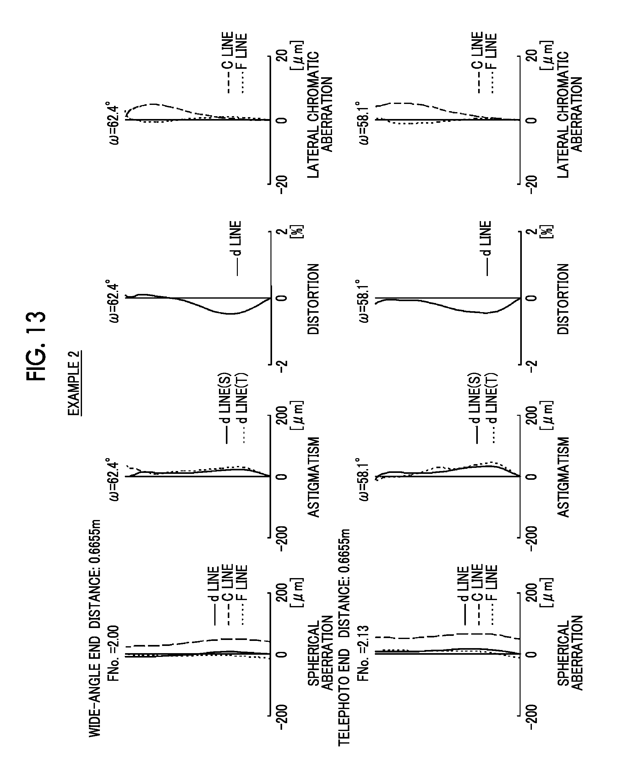
D00014
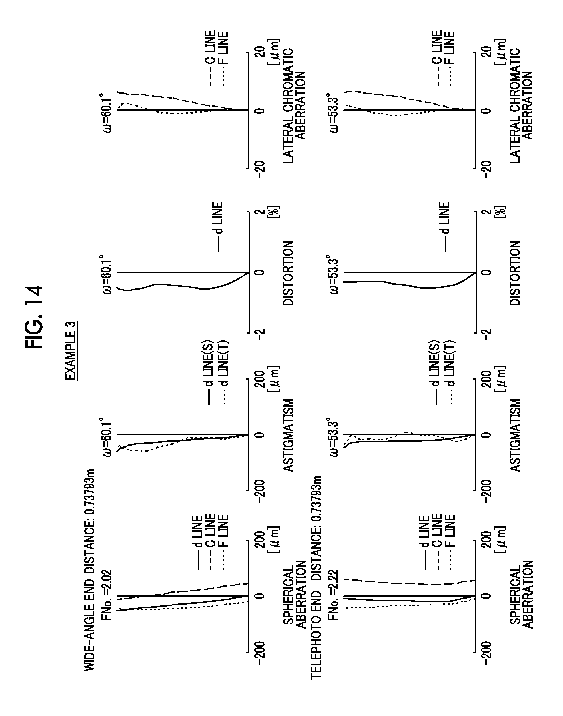
D00015
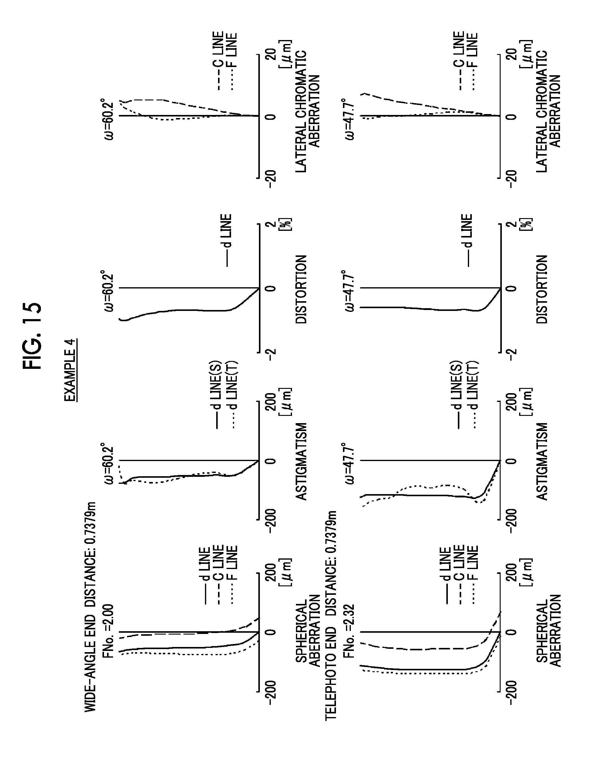
D00016

D00017
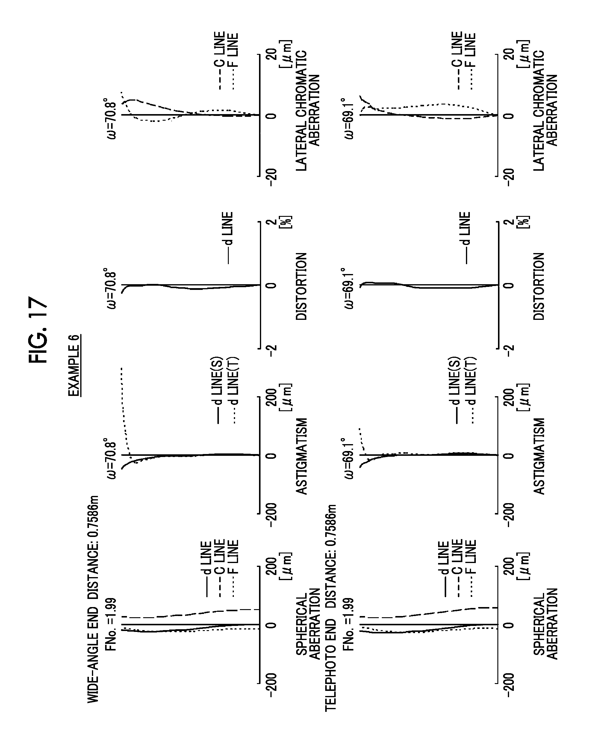
D00018
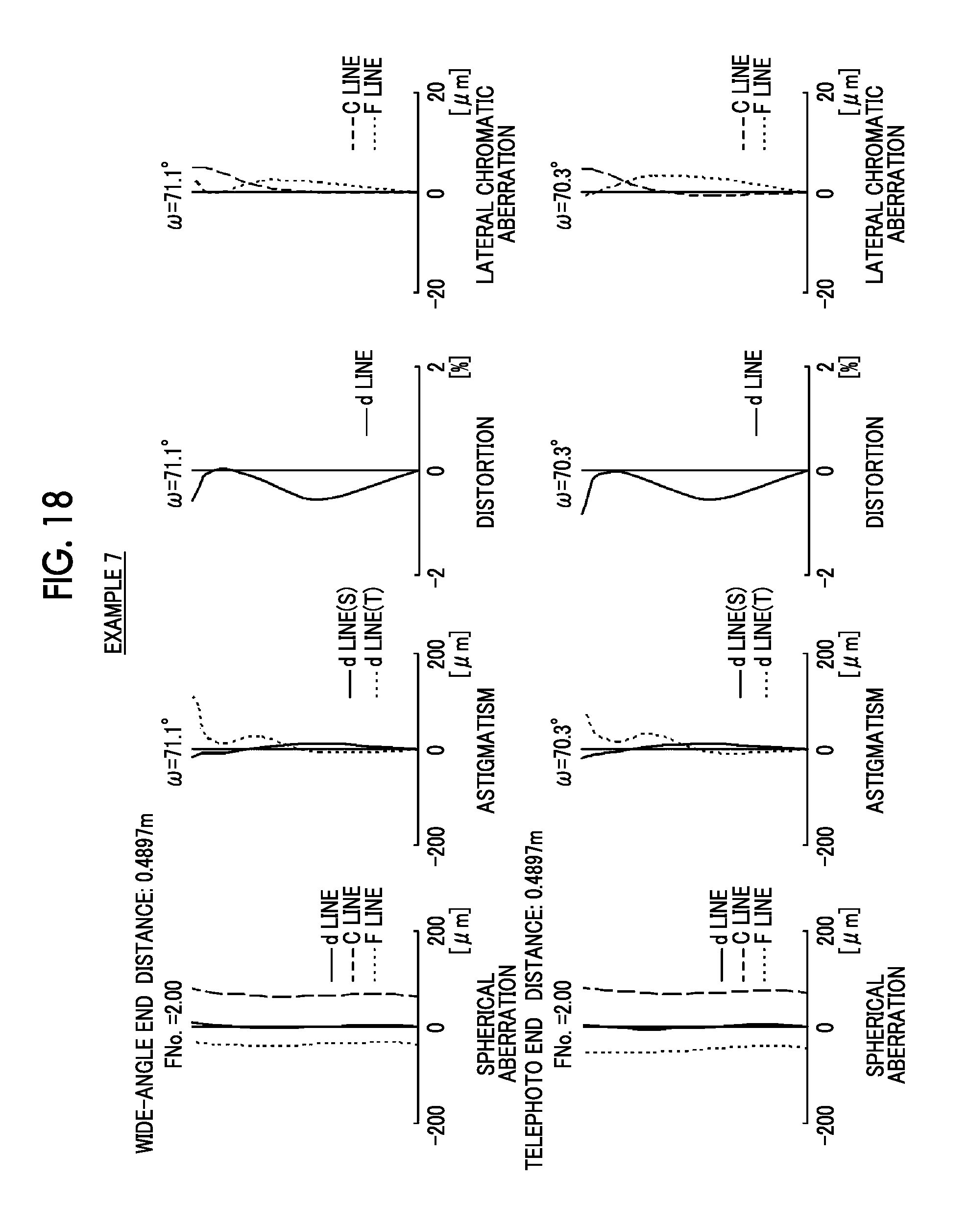
D00019
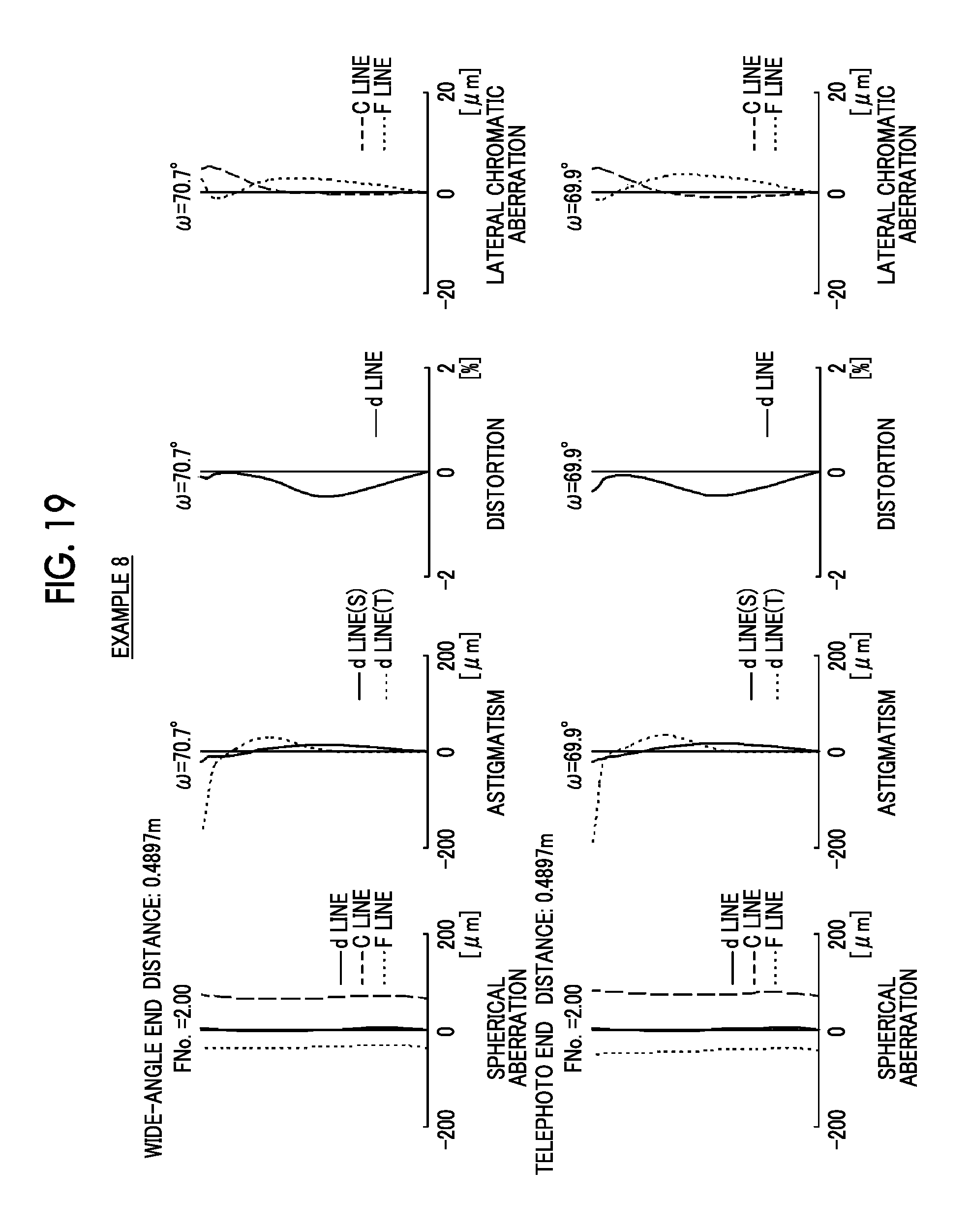
D00020
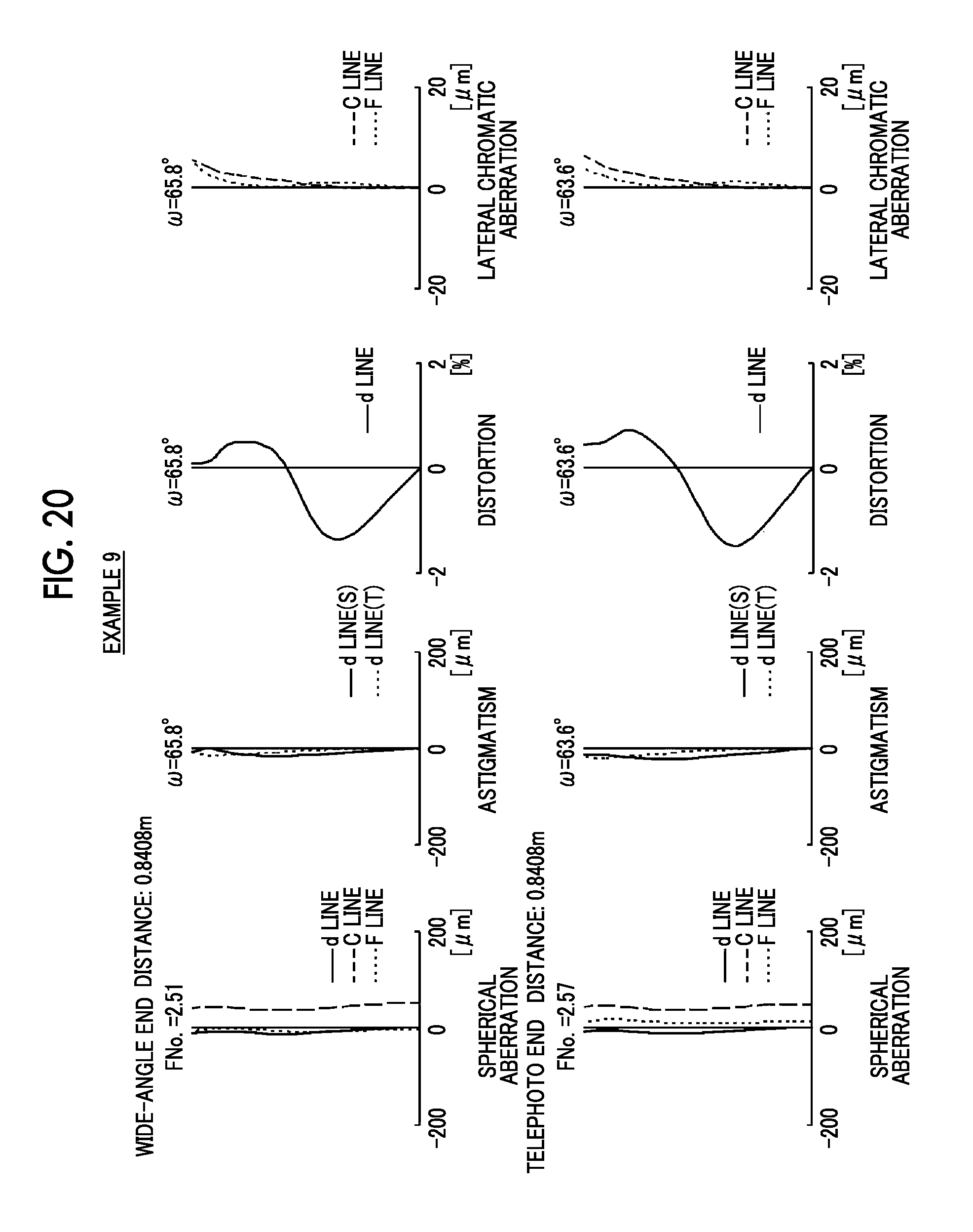
D00021

D00022

D00023

D00024
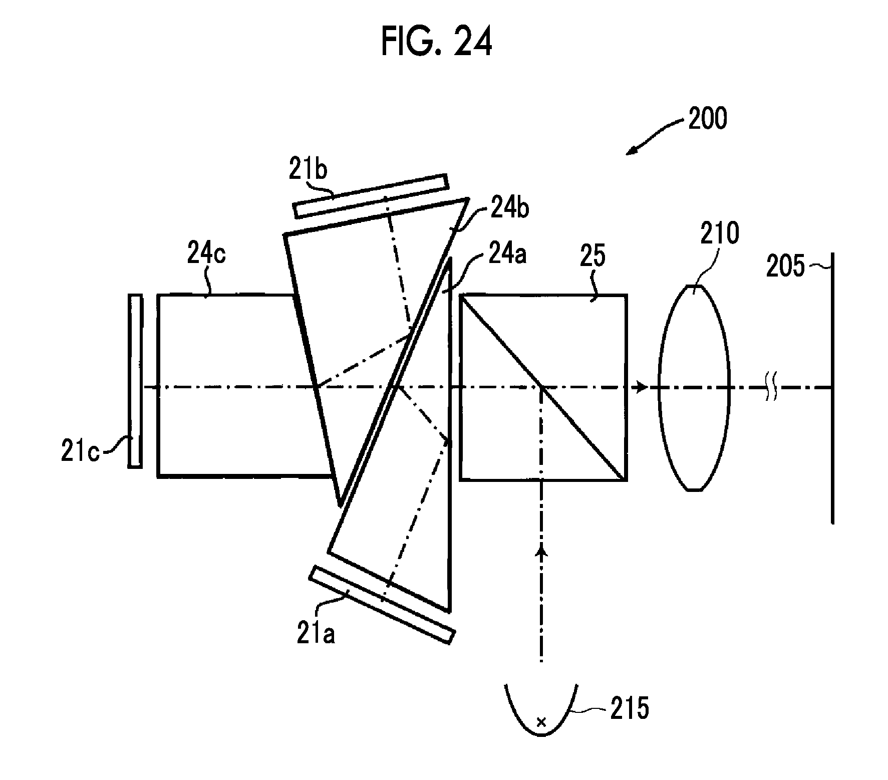
D00025

D00026
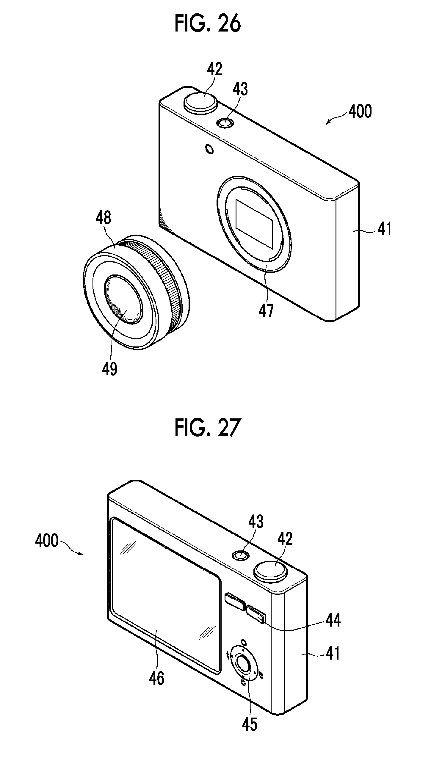
XML
uspto.report is an independent third-party trademark research tool that is not affiliated, endorsed, or sponsored by the United States Patent and Trademark Office (USPTO) or any other governmental organization. The information provided by uspto.report is based on publicly available data at the time of writing and is intended for informational purposes only.
While we strive to provide accurate and up-to-date information, we do not guarantee the accuracy, completeness, reliability, or suitability of the information displayed on this site. The use of this site is at your own risk. Any reliance you place on such information is therefore strictly at your own risk.
All official trademark data, including owner information, should be verified by visiting the official USPTO website at www.uspto.gov. This site is not intended to replace professional legal advice and should not be used as a substitute for consulting with a legal professional who is knowledgeable about trademark law.