Continuously variable transmission
Nichols , et al.
U.S. patent number 10,323,732 [Application Number 15/619,285] was granted by the patent office on 2019-06-18 for continuously variable transmission. This patent grant is currently assigned to Fallbrook Intellectual Property Company LLC. The grantee listed for this patent is Fallbrook Intellectual Property Company LLC. Invention is credited to Jon M. Nichols, Christopher M. Vasiliotis.


| United States Patent | 10,323,732 |
| Nichols , et al. | June 18, 2019 |
Continuously variable transmission
Abstract
A continuously variable transmission (CVT) can be used in concert with an electric motor to facilitate power assistance to a rider in a bicycle. In some embodiments, the CVT and motor is mounted on the frame of the bicycle at a location forward of the rear wheel hub of the bicycle. In some embodiments, the CVT is mounted on and supported by members of the bicycle frame such that the CVT is coaxial with the crankshaft of the bicycle. The crankshaft is configured to drive elements of the CVT, which are configured to operationally drive the traction rings and the traction planets. In some embodiments, the motor is configured to drive elements of the CVT. In other embodiments, the motor is configured to drive the crankshaft. Inventive component and subassemblies for such a CVT are disclosed.
| Inventors: | Nichols; Jon M. (Georgetown, TX), Vasiliotis; Christopher M. (Austin, TX) | ||||||||||
|---|---|---|---|---|---|---|---|---|---|---|---|
| Applicant: |
|
||||||||||
| Assignee: | Fallbrook Intellectual Property
Company LLC (Cedar Park, TX) |
||||||||||
| Family ID: | 50732329 | ||||||||||
| Appl. No.: | 15/619,285 | ||||||||||
| Filed: | June 9, 2017 |
Prior Publication Data
| Document Identifier | Publication Date | |
|---|---|---|
| US 20170276217 A1 | Sep 28, 2017 | |
Related U.S. Patent Documents
| Application Number | Filing Date | Patent Number | Issue Date | ||
|---|---|---|---|---|---|
| 14885846 | Oct 16, 2015 | 9677650 | |||
| PCT/US2014/034300 | Apr 16, 2014 | ||||
| 61814122 | Apr 19, 2013 | ||||
| Current U.S. Class: | 1/1 |
| Current CPC Class: | F16H 15/52 (20130101); B62M 6/45 (20130101); B62M 6/60 (20130101); B62M 6/55 (20130101) |
| Current International Class: | F16H 15/52 (20060101); B62M 6/55 (20100101); B62M 6/60 (20100101); B62M 6/45 (20100101) |
References Cited [Referenced By]
U.S. Patent Documents
| 4963 | February 1847 | Armstrong et al. |
| 719595 | February 1903 | Huss |
| 739148 | September 1903 | Buckley |
| 1121210 | December 1914 | Techel |
| 1175677 | March 1916 | Barnes |
| 1207985 | December 1916 | Null et al. |
| 1380006 | May 1921 | Nielsen |
| 1390971 | September 1921 | Samain |
| 1558222 | October 1925 | Beetow |
| 1629902 | May 1927 | Arter et al. |
| 1631069 | May 1927 | Smith |
| 1686446 | October 1928 | Gilman |
| 1774254 | August 1930 | Daukus |
| 1793571 | February 1931 | Vaughn |
| 1847027 | February 1932 | Thomsen et al. |
| 1850189 | March 1932 | Weiss |
| 1858696 | May 1932 | Weiss |
| 1865102 | June 1932 | Hayes |
| 1978439 | October 1934 | Sharpe |
| 2030203 | February 1936 | Gove et al. |
| 2060884 | November 1936 | Madle |
| 2086491 | July 1937 | Dodge |
| 2100629 | November 1937 | Chilton |
| 2109845 | March 1938 | Madle |
| 2112763 | March 1938 | Cloudsley |
| 2131158 | September 1938 | Almen et al. |
| 2134225 | October 1938 | Christiansen |
| 2152796 | April 1939 | Erban |
| 2196064 | April 1940 | Erban |
| 2209254 | July 1940 | Ahnger |
| 2230398 | February 1941 | Benjafield |
| 2259933 | October 1941 | Holloway |
| 2269434 | January 1942 | Brooks |
| 2325502 | July 1943 | Auguste |
| RE22761 | May 1946 | Wemp |
| 2461258 | February 1949 | Brooks |
| 2469653 | May 1949 | Kopp |
| 2480968 | September 1949 | Ronai |
| 2553465 | May 1951 | Monge |
| 2586725 | February 1952 | Henry |
| 2595367 | May 1952 | Picanol |
| 2596538 | May 1952 | Dicke |
| 2597849 | May 1952 | Alfredeen |
| 2675713 | April 1954 | Acker |
| 2696888 | December 1954 | Chillson et al. |
| 2868038 | May 1955 | Billeter |
| 2716357 | August 1955 | Rennerfelt |
| 2730904 | January 1956 | Rennerfelt |
| 2748614 | June 1956 | Weisel |
| 2959070 | January 1959 | Flinn |
| 2873911 | February 1959 | Perrine |
| 2874592 | February 1959 | Oehrli |
| 2883883 | April 1959 | Chillson |
| 2891213 | June 1959 | Kern |
| 2901924 | September 1959 | Banker |
| 2913932 | November 1959 | Oehrli |
| 2931234 | April 1960 | Hayward |
| 2931235 | April 1960 | Hayward |
| 2949800 | August 1960 | Neuschotz |
| 2959063 | November 1960 | Perry |
| 2959972 | November 1960 | Madson |
| 2964959 | December 1960 | Beck |
| 3008061 | November 1961 | Mims et al. |
| 3035460 | May 1962 | Guichard |
| 3048056 | August 1962 | Wolfram |
| 3051020 | August 1962 | Hartupee |
| 3071194 | January 1963 | Geske |
| 3086704 | April 1963 | Hurtt |
| 3087348 | April 1963 | Kraus |
| 3154957 | November 1964 | Kashihara |
| 3163050 | December 1964 | Kraus |
| 3176542 | April 1965 | Monch |
| 3184983 | May 1965 | Kraus |
| 3204476 | September 1965 | Rouverol |
| 3209606 | October 1965 | Yamamoto |
| 3211364 | October 1965 | Wentling et al. |
| 3216283 | November 1965 | General |
| 3229538 | January 1966 | Schlottler |
| 3237468 | March 1966 | Schlottler |
| 3246531 | April 1966 | Kashihara |
| 3248960 | May 1966 | Schottler |
| 3273468 | September 1966 | Allen |
| 3280646 | October 1966 | Lemieux |
| 3283614 | November 1966 | Hewko |
| 3292443 | December 1966 | Felix |
| 3340895 | September 1967 | Osgood, Jr. et al. |
| 3374009 | March 1968 | Jeunet |
| 3407687 | October 1968 | Hayashi |
| 3430504 | March 1969 | Dickenbrock |
| 3439563 | April 1969 | Petty |
| 3440895 | April 1969 | Fellows |
| 3464281 | September 1969 | Hiroshi et al. |
| 3477315 | November 1969 | MacKs |
| 3487726 | January 1970 | Burnett |
| 3487727 | January 1970 | Gustafsson |
| 3574289 | April 1971 | Scheiter et al. |
| 3581587 | June 1971 | Dickenbrock |
| 3661404 | May 1972 | Bossaer |
| 3695120 | October 1972 | Titt |
| 3707888 | January 1973 | Schottler |
| 3727473 | April 1973 | Bayer |
| 3727474 | April 1973 | Fullerton |
| 3736803 | June 1973 | Horowitz et al. |
| 3768715 | October 1973 | Tout |
| 3769849 | November 1973 | Hagen |
| 3800607 | April 1974 | Zurcher |
| 3802284 | April 1974 | Sharpe et al. |
| 3810398 | May 1974 | Kraus |
| 3820416 | June 1974 | Kraus |
| 3866985 | February 1975 | Whitehurst |
| 3891235 | June 1975 | Shelly |
| 3934493 | January 1976 | Hillyer |
| 3954282 | May 1976 | Hege |
| 3984129 | October 1976 | Hege |
| 3987681 | October 1976 | Keithley et al. |
| 3996807 | December 1976 | Adams |
| 4023442 | May 1977 | Woods et al. |
| 4053173 | October 1977 | Chase, Sr. |
| 4086026 | April 1978 | Tamanini |
| 4098146 | July 1978 | McLarty |
| 4103514 | August 1978 | Grosse-Entrup |
| 4158317 | June 1979 | James |
| 4159653 | July 1979 | Koivunen |
| 4169609 | October 1979 | Zampedro |
| 4177683 | December 1979 | Moses |
| 4227712 | October 1980 | Dick |
| 4314485 | February 1982 | Adams |
| 4345486 | August 1982 | Olesen |
| 4369667 | January 1983 | Kemper |
| 4391156 | July 1983 | Tibbals |
| 4459873 | July 1984 | Black |
| 4464952 | August 1984 | Stubbs |
| 4468984 | September 1984 | Castelli et al. |
| 4493677 | January 1985 | Ikenoya |
| 4494524 | January 1985 | Wagner |
| 4496051 | January 1985 | Ortner |
| 4501172 | February 1985 | Kraus |
| 4515040 | May 1985 | Takeuchi et al. |
| 4526255 | July 1985 | Hennessey et al. |
| 4546673 | October 1985 | Shigematsu et al. |
| 4549874 | October 1985 | Wen |
| 4560369 | December 1985 | Hattori |
| 4567781 | February 1986 | Russ |
| 4569670 | February 1986 | McIntosh |
| 4574649 | March 1986 | Seol |
| 4585429 | April 1986 | Marier |
| 4617838 | October 1986 | Anderson |
| 4628766 | December 1986 | De Brie Perry |
| 4630839 | December 1986 | Seol |
| 4631469 | December 1986 | Tsuboi et al. |
| 4647060 | March 1987 | Tomkinson |
| 4651082 | March 1987 | Kaneyuki |
| 4663990 | May 1987 | Itoh et al. |
| 4700581 | October 1987 | Tibbals, Jr. |
| 4713976 | December 1987 | Wilkes |
| 4717368 | January 1988 | Yamaguchi et al. |
| 4725258 | February 1988 | Joanis, Jr. |
| 4735430 | April 1988 | Tomkinson |
| 4738164 | April 1988 | Kaneyuki |
| 4744261 | May 1988 | Jacobson |
| 4756211 | July 1988 | Fellows |
| 4781663 | November 1988 | Reswick |
| 4806066 | February 1989 | Rhodes et al. |
| 4838122 | June 1989 | Takamiya et al. |
| 4856374 | August 1989 | Kreuzer |
| 4857035 | August 1989 | Anderson |
| 4869130 | September 1989 | Wiecko |
| 4881925 | November 1989 | Hattori |
| 4900046 | February 1990 | Aranceta-Angoitia |
| 4909101 | March 1990 | Terry |
| 4918344 | April 1990 | Chikamori et al. |
| 4961477 | October 1990 | Sweeney |
| 4964312 | October 1990 | Kraus |
| 5006093 | April 1991 | Itoh et al. |
| 5020384 | June 1991 | Kraus |
| 5025685 | June 1991 | Kobayashi et al. |
| 5033322 | July 1991 | Nakano |
| 5033571 | July 1991 | Morimoto |
| 5037361 | August 1991 | Takahashi |
| 5044214 | September 1991 | Barber |
| 5059158 | October 1991 | Bellio et al. |
| 5069655 | December 1991 | Schivelbusch |
| 5083982 | January 1992 | Sato |
| 5099710 | March 1992 | Nakano |
| 5121654 | June 1992 | Fasce |
| 5125677 | June 1992 | Ogilvie et al. |
| 5138894 | August 1992 | Kraus |
| 5156412 | October 1992 | Meguerditchian |
| 5230258 | July 1993 | Nakano |
| 5236211 | August 1993 | Meguerditchian |
| 5236403 | August 1993 | Schievelbusch |
| 5261858 | November 1993 | Browning |
| 5267920 | December 1993 | Hibi |
| 5273501 | December 1993 | Schievelbusch |
| 5318486 | June 1994 | Lutz |
| 5319486 | June 1994 | Vogel et al. |
| 5323570 | June 1994 | Kuhlman et al. |
| 5330396 | July 1994 | Lohr et al. |
| 5355749 | October 1994 | Obara et al. |
| 5356348 | October 1994 | Bellio et al. |
| 5375865 | December 1994 | Terry, Sr. |
| 5379661 | January 1995 | Nakano |
| 5383677 | January 1995 | Thomas |
| 5387000 | February 1995 | Sato |
| 5401221 | March 1995 | Fellows et al. |
| 5451070 | September 1995 | Lindsay et al. |
| 5489003 | February 1996 | Ohyama et al. |
| 5508574 | April 1996 | Vlock |
| 5562564 | October 1996 | Folino |
| 5564998 | October 1996 | Fellows |
| 5601301 | February 1997 | Liu |
| 5607373 | March 1997 | Ochiai et al. |
| 5645507 | July 1997 | Hathaway |
| 5651750 | July 1997 | Imanishi et al. |
| 5664636 | September 1997 | Ikuma et al. |
| 5669758 | September 1997 | Williamson |
| 5669845 | September 1997 | Muramoto et al. |
| 5690346 | November 1997 | Keskitalo |
| 5701786 | December 1997 | Kawakami |
| 5722502 | March 1998 | Kubo |
| 5746676 | May 1998 | Kawase et al. |
| 5755303 | May 1998 | Yamamoto et al. |
| 5799541 | September 1998 | Arbeiter |
| 5823052 | October 1998 | Nobumoto |
| 5846155 | December 1998 | Taniguchi et al. |
| 5888160 | March 1999 | Miyata et al. |
| 5895337 | April 1999 | Fellows et al. |
| 5899827 | May 1999 | Nakano et al. |
| 5902207 | May 1999 | Sugihara |
| 5967933 | October 1999 | Valdenaire |
| 5976054 | November 1999 | Yasuoka |
| 5984826 | November 1999 | Nakano |
| 5995895 | November 1999 | Watt et al. |
| 6000707 | December 1999 | Miller |
| 6003649 | December 1999 | Fischer |
| 6004239 | December 1999 | Makino |
| 6006151 | December 1999 | Graf |
| 6012538 | January 2000 | Sonobe et al. |
| 6015359 | January 2000 | Kunii |
| 6019701 | February 2000 | Mori et al. |
| 6029990 | February 2000 | Busby |
| 6042132 | March 2000 | Suenaga et al. |
| 6045477 | April 2000 | Schmidt |
| 6045481 | April 2000 | Kumagai |
| 6050854 | April 2000 | Fang et al. |
| 6053833 | April 2000 | Masaki |
| 6053841 | April 2000 | Kolde et al. |
| 6054844 | April 2000 | Frank |
| 6066067 | May 2000 | Greenwood |
| 6071210 | June 2000 | Kato |
| 6074320 | June 2000 | Miyata et al. |
| 6076846 | June 2000 | Clardy |
| 6079726 | June 2000 | Busby |
| 6083139 | July 2000 | Deguchi |
| 6086506 | July 2000 | Petersmann et al. |
| 6095940 | August 2000 | Ai et al. |
| 6099431 | August 2000 | Hoge et al. |
| 6101895 | August 2000 | Yamane |
| 6113513 | September 2000 | Itoh et al. |
| 6119539 | September 2000 | Papanicolaou |
| 6119800 | September 2000 | McComber |
| 6155132 | December 2000 | Yamane |
| 6159126 | December 2000 | Oshidari |
| 6171210 | January 2001 | Miyata et al. |
| 6174260 | January 2001 | Tsukada et al. |
| 6186922 | February 2001 | Bursal et al. |
| 6201315 | March 2001 | Larsson |
| 6210297 | April 2001 | Knight |
| 6217473 | April 2001 | Ueda et al. |
| 6217478 | April 2001 | Vohmann et al. |
| 6241636 | June 2001 | Miller |
| 6243638 | June 2001 | Abo et al. |
| 6251038 | June 2001 | Ishikawa et al. |
| 6258003 | July 2001 | Hirano et al. |
| 6261200 | July 2001 | Miyata et al. |
| 6293575 | September 2001 | Burrows et al. |
| 6296593 | October 2001 | Gotou |
| 6311113 | October 2001 | Danz et al. |
| 6312358 | November 2001 | Goi et al. |
| 6322475 | November 2001 | Miller |
| 6325386 | December 2001 | Shoge |
| 6340067 | January 2002 | Fujiwara |
| 6358174 | March 2002 | Folsom et al. |
| 6358178 | March 2002 | Wittkopp |
| 6367833 | April 2002 | Horiuchi |
| 6371878 | April 2002 | Bowen |
| 6375412 | April 2002 | Dial |
| 6390945 | May 2002 | Young |
| 6390946 | May 2002 | Hibi et al. |
| 6406399 | June 2002 | Ai |
| 6414401 | July 2002 | Kuroda et al. |
| 6419608 | July 2002 | Miller |
| 6425838 | July 2002 | Matsubara et al. |
| 6434960 | August 2002 | Rousseau |
| 6440037 | August 2002 | Takagi et al. |
| 6459978 | October 2002 | Tamiguchi et al. |
| 6461268 | October 2002 | Milner |
| 6482094 | November 2002 | Kefes |
| 6492785 | December 2002 | Kasten et al. |
| 6494805 | December 2002 | Ooyama et al. |
| 6499373 | December 2002 | Van Cor |
| 6514175 | February 2003 | Taniguchi et al. |
| 6523223 | February 2003 | Wang |
| 6532890 | March 2003 | Chen |
| 6551210 | April 2003 | Miller |
| 6558285 | May 2003 | Sieber |
| 6571726 | June 2003 | Tsai et al. |
| 6575047 | June 2003 | Reik et al. |
| 6659901 | December 2003 | Sakai et al. |
| 6672418 | January 2004 | Makino |
| 6676559 | January 2004 | Miller |
| 6679109 | January 2004 | Gierling et al. |
| 6682432 | January 2004 | Shinozuka |
| 6689012 | February 2004 | Miller |
| 6721637 | April 2004 | Abe et al. |
| 6723014 | April 2004 | Shinso et al. |
| 6723016 | April 2004 | Sumi |
| 6805654 | October 2004 | Nishii |
| 6808053 | October 2004 | Kirkwood et al. |
| 6839617 | January 2005 | Mensler et al. |
| 6849020 | February 2005 | Sumi |
| 6859709 | February 2005 | Joe et al. |
| 6868949 | March 2005 | Braford |
| 6931316 | August 2005 | Joe et al. |
| 6932739 | August 2005 | Miyata et al. |
| 6942593 | September 2005 | Nishii et al. |
| 6945903 | September 2005 | Miller |
| 6949049 | September 2005 | Miller |
| 6958029 | October 2005 | Inoue |
| 6991575 | January 2006 | Inoue |
| 6991579 | January 2006 | Kobayashi et al. |
| 7000496 | February 2006 | Wessel et al. |
| 7011600 | March 2006 | Miller et al. |
| 7011601 | March 2006 | Miller |
| 7014591 | March 2006 | Miller |
| 7029418 | April 2006 | Taketsuna et al. |
| 7032914 | April 2006 | Miller |
| 7036620 | May 2006 | Miller et al. |
| 7044884 | May 2006 | Miller |
| 7063195 | June 2006 | Berhan |
| 7063640 | June 2006 | Miller |
| 7074007 | July 2006 | Miller |
| 7074154 | July 2006 | Miller |
| 7074155 | July 2006 | Miller |
| 7077777 | July 2006 | Miyata et al. |
| 7086979 | August 2006 | Frenken |
| 7086981 | August 2006 | Ali et al. |
| 7094171 | August 2006 | Inoue |
| 7111860 | September 2006 | Grimaldos |
| 7112158 | September 2006 | Miller |
| 7112159 | September 2006 | Miller et al. |
| 7125297 | October 2006 | Miller et al. |
| 7131930 | November 2006 | Miller et al. |
| 7140999 | November 2006 | Miller |
| 7147586 | December 2006 | Miller et al. |
| 7153233 | December 2006 | Miller et al. |
| 7156770 | January 2007 | Miller |
| 7160220 | January 2007 | Shinojima et al. |
| 7160222 | January 2007 | Miller |
| 7163485 | January 2007 | Miller |
| 7163486 | January 2007 | Miller et al. |
| 7166052 | January 2007 | Miller et al. |
| 7166056 | January 2007 | Miller et al. |
| 7166057 | January 2007 | Miller et al. |
| 7166058 | January 2007 | Miller et al. |
| 7169076 | January 2007 | Miller et al. |
| 7172529 | February 2007 | Miller et al. |
| 7175564 | February 2007 | Miller |
| 7175565 | February 2007 | Miller et al. |
| 7175566 | February 2007 | Miller et al. |
| 7192381 | March 2007 | Miller et al. |
| 7197915 | April 2007 | Luh et al. |
| 7198582 | April 2007 | Miller et al. |
| 7198583 | April 2007 | Miller et al. |
| 7198584 | April 2007 | Miller et al. |
| 7198585 | April 2007 | Miller et al. |
| 7201693 | April 2007 | Miller et al. |
| 7201694 | April 2007 | Miller et al. |
| 7201695 | April 2007 | Miller et al. |
| 7204777 | April 2007 | Miller et al. |
| 7207918 | April 2007 | Shimazu |
| 7214159 | May 2007 | Miller et al. |
| 7217215 | May 2007 | Miller et al. |
| 7217216 | May 2007 | Inoue |
| 7217219 | May 2007 | Miller |
| 7217220 | May 2007 | Careau et al. |
| 7232395 | June 2007 | Miller et al. |
| 7234873 | June 2007 | Kato et al. |
| 7235031 | June 2007 | Miller et al. |
| D546741 | July 2007 | Iteya et al. |
| 7238136 | July 2007 | Miller et al. |
| 7238137 | July 2007 | Miller et al. |
| 7238138 | July 2007 | Miller et al. |
| 7238139 | July 2007 | Roethler et al. |
| 7246672 | July 2007 | Shirai et al. |
| 7250018 | July 2007 | Miller et al. |
| D548655 | August 2007 | Barrow et al. |
| 7261663 | August 2007 | Miller |
| 7275610 | October 2007 | Kuang et al. |
| 7285068 | October 2007 | Hosoi |
| 7288042 | October 2007 | Miller et al. |
| 7288043 | October 2007 | Shioiri et al. |
| 7320660 | January 2008 | Miller |
| 7322901 | January 2008 | Miller et al. |
| 7343236 | March 2008 | Wilson |
| 7347801 | March 2008 | Guenter et al. |
| 7383748 | June 2008 | Rankin |
| 7384370 | June 2008 | Miller |
| 7393300 | July 2008 | Miller et al. |
| 7393302 | July 2008 | Miller |
| 7393303 | July 2008 | Miller |
| 7395731 | July 2008 | Miller et al. |
| 7396209 | July 2008 | Miller et al. |
| 7402122 | July 2008 | Miller |
| 7410443 | August 2008 | Miller |
| 7419451 | September 2008 | Miller |
| 7422541 | September 2008 | Miller |
| 7422546 | September 2008 | Miller et al. |
| 7427253 | September 2008 | Miller |
| 7431677 | October 2008 | Miller et al. |
| D579833 | November 2008 | Acenbrak |
| 7452297 | November 2008 | Miller et al. |
| 7455611 | November 2008 | Miller et al. |
| 7455617 | November 2008 | Miller et al. |
| 7462123 | December 2008 | Miller et al. |
| 7462127 | December 2008 | Miller et al. |
| 7470210 | December 2008 | Miller et al. |
| 7478885 | January 2009 | Urabe |
| 7481736 | January 2009 | Miller et al. |
| 7510499 | March 2009 | Miller et al. |
| 7540818 | June 2009 | Miller et al. |
| 7547264 | June 2009 | Usoro |
| 7574935 | August 2009 | Rohs et al. |
| 7591755 | September 2009 | Petrzik et al. |
| 7600771 | October 2009 | Miller et al. |
| 7632203 | December 2009 | Miller |
| 7651437 | January 2010 | Miller et al. |
| 7654928 | February 2010 | Miller et al. |
| 7670243 | March 2010 | Miller |
| 7686729 | March 2010 | Miller et al. |
| 7727101 | June 2010 | Miller |
| 7727106 | June 2010 | Maheu et al. |
| 7727107 | June 2010 | Miller |
| 7727108 | June 2010 | Miller et al. |
| 7727110 | June 2010 | Miller et al. |
| 7727115 | June 2010 | Serkh |
| 7731615 | June 2010 | Miller et al. |
| 7762919 | July 2010 | Smithson et al. |
| 7762920 | July 2010 | Smithson et al. |
| 7785228 | August 2010 | Smithson et al. |
| 7828685 | November 2010 | Miller |
| 7837592 | November 2010 | Miller |
| 7871353 | January 2011 | Nichols et al. |
| 7882762 | February 2011 | Armstrong et al. |
| 7883442 | February 2011 | Miller et al. |
| 7885747 | February 2011 | Miller et al. |
| 7887032 | February 2011 | Malone |
| 7909723 | March 2011 | Triller et al. |
| 7909727 | March 2011 | Smithson et al. |
| 7914029 | March 2011 | Miller et al. |
| 7959533 | June 2011 | Nichols et al. |
| 7963880 | June 2011 | Smithson et al. |
| 7967719 | June 2011 | Smithson et al. |
| 7976426 | July 2011 | Smithson et al. |
| 8066613 | November 2011 | Smithson et al. |
| 8066614 | November 2011 | Miller et al. |
| 8070635 | December 2011 | Miller |
| 8087482 | January 2012 | Miles et al. |
| 8123653 | February 2012 | Smithson et al. |
| 8133149 | March 2012 | Smithson et al. |
| 8142323 | March 2012 | Tsuchiya et al. |
| 8167759 | May 2012 | Pohl et al. |
| 8171636 | May 2012 | Smithson et al. |
| 8230961 | July 2012 | Schneidewind |
| 8262536 | September 2012 | Nichols et al. |
| 8267829 | September 2012 | Miller et al. |
| 8313404 | November 2012 | Carter et al. |
| 8313405 | November 2012 | Bazyn et al. |
| 8317650 | November 2012 | Nichols et al. |
| 8317651 | November 2012 | Lohr |
| 8321097 | November 2012 | Vasiliotis et al. |
| 8342999 | January 2013 | Miller |
| 8360917 | January 2013 | Nichols et al. |
| 8376889 | February 2013 | Hoffman et al. |
| 8376903 | February 2013 | Pohl et al. |
| 8382631 | February 2013 | Hoffman et al. |
| 8382637 | February 2013 | Tange |
| 8393989 | March 2013 | Pohl |
| 8398518 | March 2013 | Nichols et al. |
| 8469853 | June 2013 | Miller et al. |
| 8469856 | June 2013 | Thomassy |
| 8480529 | July 2013 | Pohl et al. |
| 8496554 | July 2013 | Pohl et al. |
| 8506452 | August 2013 | Pohl et al. |
| 8512195 | August 2013 | Lohr et al. |
| 8517888 | August 2013 | Brookins |
| 8535199 | September 2013 | Lohr et al. |
| 8550949 | October 2013 | Miller |
| 8585528 | November 2013 | Carter et al. |
| 8608609 | December 2013 | Sherrill |
| 8622866 | January 2014 | Bazyn et al. |
| 8626409 | January 2014 | Vasiliotis et al. |
| 8628443 | January 2014 | Miller et al. |
| 8641572 | February 2014 | Nichols et al. |
| 8641577 | February 2014 | Nichols et al. |
| 8663050 | March 2014 | Nichols et al. |
| 8678974 | March 2014 | Lohr |
| 8708360 | April 2014 | Miller et al. |
| 8721485 | May 2014 | Lohr et al. |
| 8738255 | May 2014 | Carter et al. |
| 8776633 | July 2014 | Armstrong et al. |
| 8784248 | July 2014 | Murakami et al. |
| 8790214 | July 2014 | Lohr et al. |
| 8814739 | August 2014 | Hamrin et al. |
| 8818661 | August 2014 | Keilers et al. |
| 8827856 | September 2014 | Younggren et al. |
| 8827864 | September 2014 | Durack |
| 8845485 | September 2014 | Smithson et al. |
| 8852050 | October 2014 | Thomassy |
| 8870711 | October 2014 | Pohl et al. |
| 8888643 | November 2014 | Lohr et al. |
| 8900085 | December 2014 | Pohl et al. |
| 8920285 | December 2014 | Smithson et al. |
| 8924111 | December 2014 | Fuller |
| 8956262 | February 2015 | Tomomatsu et al. |
| 8961363 | February 2015 | Shiina et al. |
| 8992376 | March 2015 | Ogawa et al. |
| 8996263 | March 2015 | Quinn et al. |
| 9017207 | April 2015 | Pohl et al. |
| 9022889 | May 2015 | Miller |
| 9046158 | June 2015 | Miller et al. |
| 9074674 | July 2015 | Nichols et al. |
| 9086145 | July 2015 | Pohl et al. |
| 9121464 | September 2015 | Nichols et al. |
| 9182018 | November 2015 | Bazyn et al. |
| 9239099 | January 2016 | Carter et al. |
| 9249880 | February 2016 | Vasiliotis et al. |
| 9273760 | March 2016 | Pohl et al. |
| 9279482 | March 2016 | Nichols et al. |
| 9291251 | March 2016 | Lohr et al. |
| 9328807 | May 2016 | Carter et al. |
| 9341246 | May 2016 | Miller et al. |
| 9360089 | June 2016 | Lohr et al. |
| 9365203 | June 2016 | Keilers et al. |
| 9371894 | June 2016 | Carter et al. |
| 9506562 | November 2016 | Miller et al. |
| 9528561 | December 2016 | Nichols et al. |
| 9574642 | February 2017 | Pohl et al. |
| 9574643 | February 2017 | Pohl |
| 9611921 | April 2017 | Thomassy et al. |
| 9618100 | April 2017 | Lohr |
| 9656672 | May 2017 | Schieffelin |
| 9676391 | June 2017 | Carter et al. |
| 9677650 | June 2017 | Nichols |
| 9683638 | June 2017 | Kostrup |
| 9683640 | June 2017 | Lohr et al. |
| 9726282 | August 2017 | Pohl |
| 9878719 | January 2018 | Carter et al. |
| 9963199 | May 2018 | Hancock et al. |
| 10023266 | July 2018 | Contello et al. |
| 10047861 | August 2018 | Thomassy et al. |
| 10056811 | August 2018 | Pohl |
| 2001/0008192 | July 2001 | Morisawa |
| 2001/0023217 | September 2001 | Miyagawa et al. |
| 2001/0041644 | November 2001 | Yasuoka et al. |
| 2001/0044358 | November 2001 | Taniguchi |
| 2001/0044361 | November 2001 | Taniguchi et al. |
| 2002/0019285 | February 2002 | Henzler |
| 2002/0028722 | March 2002 | Sakai et al. |
| 2002/0037786 | March 2002 | Hirano et al. |
| 2002/0045511 | April 2002 | Geiberger et al. |
| 2002/0049113 | April 2002 | Watanabe et al. |
| 2002/0117860 | August 2002 | Man et al. |
| 2002/0128107 | September 2002 | Wakayama |
| 2002/0153695 | October 2002 | Wang |
| 2002/0161503 | October 2002 | Joe et al. |
| 2002/0169051 | November 2002 | Oshidari |
| 2002/0179348 | December 2002 | Tamai et al. |
| 2002/0189524 | December 2002 | Chen |
| 2003/0015358 | January 2003 | Abe et al. |
| 2003/0015874 | January 2003 | Abe et al. |
| 2003/0022753 | January 2003 | Mizuno et al. |
| 2003/0036456 | February 2003 | Skrabs |
| 2003/0096674 | May 2003 | Uno |
| 2003/0132051 | July 2003 | Nishii et al. |
| 2003/0135316 | July 2003 | Kawamura et al. |
| 2003/0144105 | July 2003 | O'Hora |
| 2003/0160420 | August 2003 | Fukuda |
| 2003/0176247 | September 2003 | Gottschalk |
| 2003/0216216 | November 2003 | Inoue et al. |
| 2003/0221892 | December 2003 | Matsumoto et al. |
| 2004/0038772 | February 2004 | McIndoe et al. |
| 2004/0058772 | March 2004 | Inoue et al. |
| 2004/0067816 | April 2004 | Taketsuna et al. |
| 2004/0082421 | April 2004 | Wafzig |
| 2004/0092359 | May 2004 | Imanishi et al. |
| 2004/0119345 | June 2004 | Takano |
| 2004/0171457 | September 2004 | Fuller |
| 2004/0204283 | October 2004 | Inoue |
| 2004/0231331 | November 2004 | Iwanami et al. |
| 2004/0237698 | December 2004 | Hilsky et al. |
| 2004/0254047 | December 2004 | Frank et al. |
| 2005/0037876 | February 2005 | Unno et al. |
| 2005/0064986 | March 2005 | Ginglas |
| 2005/0085979 | April 2005 | Carlson et al. |
| 2005/0172752 | August 2005 | Florczyk et al. |
| 2005/0181905 | August 2005 | Ali et al. |
| 2005/0184580 | August 2005 | Kuan et al. |
| 2005/0227809 | October 2005 | Bitzer et al. |
| 2005/0229731 | October 2005 | Parks et al. |
| 2005/0233846 | October 2005 | Green et al. |
| 2006/0000684 | January 2006 | Agner |
| 2006/0006008 | January 2006 | Brunemann et al. |
| 2006/0052204 | March 2006 | Eckert et al. |
| 2006/0054422 | March 2006 | Dimsey et al. |
| 2006/0108956 | May 2006 | Clark |
| 2006/0111212 | May 2006 | Ai et al. |
| 2006/0154775 | July 2006 | Ali et al. |
| 2006/0172829 | August 2006 | Ishio |
| 2006/0180363 | August 2006 | Uchisasai |
| 2006/0223667 | October 2006 | Nakazeki |
| 2006/0234822 | October 2006 | Morscheck et al. |
| 2006/0234826 | October 2006 | Moehlmann et al. |
| 2006/0276299 | December 2006 | Imanishi |
| 2007/0004552 | January 2007 | Matsudaira et al. |
| 2007/0004556 | January 2007 | Rohs et al. |
| 2007/0041823 | February 2007 | Miller |
| 2007/0099753 | May 2007 | Matsui et al. |
| 2007/0149342 | June 2007 | Guenter et al. |
| 2007/0155552 | July 2007 | De Cloe |
| 2007/0155567 | July 2007 | Miller et al. |
| 2007/0193391 | August 2007 | Armstrong et al. |
| 2007/0228687 | October 2007 | Parker |
| 2007/0232423 | October 2007 | Katou et al. |
| 2008/0009389 | January 2008 | Jacobs |
| 2008/0032852 | February 2008 | Smithson et al. |
| 2008/0032854 | February 2008 | Smithson et al. |
| 2008/0039269 | February 2008 | Smithson et al. |
| 2008/0039273 | February 2008 | Smithson et al. |
| 2008/0039276 | February 2008 | Smithson et al. |
| 2008/0070729 | March 2008 | Miller et al. |
| 2008/0073137 | March 2008 | Miller et al. |
| 2008/0073467 | March 2008 | Miller et al. |
| 2008/0079236 | April 2008 | Miller et al. |
| 2008/0081715 | April 2008 | Miller et al. |
| 2008/0081728 | April 2008 | Faulring et al. |
| 2008/0085795 | April 2008 | Miller et al. |
| 2008/0085796 | April 2008 | Miller et al. |
| 2008/0085797 | April 2008 | Miller et al. |
| 2008/0085798 | April 2008 | Miller et al. |
| 2008/0139363 | June 2008 | Williams |
| 2008/0149407 | June 2008 | Shibata et al. |
| 2008/0183358 | July 2008 | Thomson et al. |
| 2008/0200300 | August 2008 | Smithson et al. |
| 2008/0228362 | September 2008 | Muller et al. |
| 2008/0284170 | November 2008 | Cory |
| 2008/0305920 | December 2008 | Nishii et al. |
| 2009/0023545 | January 2009 | Beaudoin |
| 2009/0082169 | March 2009 | Kolstrup |
| 2009/0107454 | April 2009 | Hiyoshi et al. |
| 2009/0251013 | October 2009 | Vollmer et al. |
| 2010/0093479 | April 2010 | Carter et al. |
| 2010/0145573 | June 2010 | Vasilescu |
| 2010/0181130 | July 2010 | Chou |
| 2011/0127096 | June 2011 | Schneidewind |
| 2011/0230297 | September 2011 | Shiina et al. |
| 2011/0237385 | September 2011 | Andre Parise |
| 2011/0291507 | December 2011 | Post |
| 2011/0319222 | December 2011 | Ogawa et al. |
| 2012/0035011 | February 2012 | Menachem et al. |
| 2012/0035015 | February 2012 | Ogawa et al. |
| 2012/0258839 | October 2012 | Smithson et al. |
| 2013/0035200 | February 2013 | Noji et al. |
| 2013/0053211 | February 2013 | Fukuda et al. |
| 2014/0148303 | May 2014 | Nichols et al. |
| 2014/0274536 | September 2014 | Versteyhe |
| 2015/0018154 | January 2015 | Thomassy |
| 2015/0051801 | February 2015 | Quinn et al. |
| 2015/0080165 | March 2015 | Pohl et al. |
| 2015/0226323 | August 2015 | Pohl et al. |
| 2015/0260284 | September 2015 | Miller et al. |
| 2015/0337928 | November 2015 | Smithson |
| 2015/0345599 | December 2015 | Ogawa |
| 2015/0369348 | December 2015 | Nichols et al. |
| 2016/0003349 | January 2016 | Kimura et al. |
| 2016/0031526 | February 2016 | Watarai |
| 2016/0061301 | March 2016 | Bazyn et al. |
| 2016/0131231 | May 2016 | Carter et al. |
| 2016/0146342 | May 2016 | Vasiliotis et al. |
| 2016/0186847 | June 2016 | Nichols et al. |
| 2016/0201772 | July 2016 | Lohr et al. |
| 2016/0273627 | September 2016 | Miller et al. |
| 2016/0281825 | September 2016 | Lohr et al. |
| 2016/0290451 | October 2016 | Lohr |
| 2016/0298740 | October 2016 | Carter et al. |
| 2016/0347411 | December 2016 | Yamamoto et al. |
| 2016/0362108 | December 2016 | Keilers et al. |
| 2017/0072782 | March 2017 | Miller et al. |
| 2017/0082049 | March 2017 | David et al. |
| 2017/0103053 | April 2017 | Nichols et al. |
| 2017/0159812 | June 2017 | Pohl et al. |
| 2017/0204948 | July 2017 | Thomassy et al. |
| 2017/0211698 | July 2017 | Lohr |
| 2017/0225742 | August 2017 | Hancock et al. |
| 2017/0268638 | September 2017 | Nichols et al. |
| 2017/0284519 | October 2017 | Kolstrup |
| 2017/0284520 | October 2017 | Lohr et al. |
| 2017/0314655 | November 2017 | Miller et al. |
| 2017/0328470 | November 2017 | Pohl |
| 2017/0335961 | November 2017 | Hamrin |
| 2017/0343105 | November 2017 | Vasiliotis et al. |
| 2018/0066754 | March 2018 | Miller et al. |
| 2018/0106359 | April 2018 | Bazyn et al. |
| 2018/0134750 | May 2018 | Pohl et al. |
| 2018/0148055 | May 2018 | Carter et al. |
| 2018/0148056 | May 2018 | Keilers et al. |
| 2018/0195586 | July 2018 | Thomassy et al. |
| 2018/0202527 | July 2018 | Nichols et al. |
| 2018/0236867 | August 2018 | Miller et al. |
| 2018/0251190 | September 2018 | Hancock et al. |
| 2018/0306283 | October 2018 | Engesather et al. |
| 2018/0327060 | November 2018 | Contello et al. |
| 118064 | Dec 1926 | CH | |||
| 1054340 | Sep 1991 | CN | |||
| 2245830 | Jan 1997 | CN | |||
| 1157379 | Aug 1997 | CN | |||
| 1167221 | Dec 1997 | CN | |||
| 1178573 | Apr 1998 | CN | |||
| 1178751 | Apr 1998 | CN | |||
| 1204991 | Jan 1999 | CN | |||
| 1283258 | Feb 2001 | CN | |||
| 1300355 | Jun 2001 | CN | |||
| 1412033 | Apr 2003 | CN | |||
| 1434229 | Aug 2003 | CN | |||
| 1474917 | Feb 2004 | CN | |||
| 1483235 | Mar 2004 | CN | |||
| 1568407 | Jan 2005 | CN | |||
| 1654858 | Aug 2005 | CN | |||
| 2714896 | Aug 2005 | CN | |||
| 1736791 | Feb 2006 | CN | |||
| 1847702 | Oct 2006 | CN | |||
| 1860315 | Nov 2006 | CN | |||
| 1940348 | Apr 2007 | CN | |||
| 101016076 | Aug 2007 | CN | |||
| 498 701 | May 1930 | DE | |||
| 1171692 | Jun 1964 | DE | |||
| 2021027 | Dec 1970 | DE | |||
| 2 310880 | Sep 1974 | DE | |||
| 2 136 243 | Jan 1975 | DE | |||
| 2436496 | Feb 1975 | DE | |||
| 263566 | Jan 1989 | DE | |||
| 19851738 | May 2000 | DE | |||
| 10155372 | May 2003 | DE | |||
| 102011016672 | Oct 2012 | DE | |||
| 102012023551 | Jun 2014 | DE | |||
| 102014007271 | Dec 2014 | DE | |||
| 0 432 742 | Dec 1990 | EP | |||
| 0 528 381 | Feb 1993 | EP | |||
| 0 528 382 | Feb 1993 | EP | |||
| 0 635 639 | Jan 1995 | EP | |||
| 0 638 741 | Feb 1995 | EP | |||
| 0 831 249 | Mar 1998 | EP | |||
| 0 832 816 | Apr 1998 | EP | |||
| 0 976 956 | Feb 2000 | EP | |||
| 1 136 724 | Sep 2001 | EP | |||
| 1 251 294 | Oct 2002 | EP | |||
| 1 366 978 | Mar 2003 | EP | |||
| 1 362 783 | Nov 2003 | EP | |||
| 1 433 641 | Jun 2004 | EP | |||
| 1 452 441 | Sep 2004 | EP | |||
| 1 518 785 | Mar 2005 | EP | |||
| 1 624 230 | Feb 2006 | EP | |||
| 2 893 219 | Jul 2015 | EP | |||
| 620375 | Apr 1927 | FR | |||
| 2460427 | Jan 1981 | FR | |||
| 2590638 | May 1987 | FR | |||
| 14132 | May 1910 | GB | |||
| 391448 | Apr 1933 | GB | |||
| 592320 | Sep 1947 | GB | |||
| 858710 | Jan 1961 | GB | |||
| 906002 | Sep 1962 | GB | |||
| 919430 | Feb 1963 | GB | |||
| 1132473 | Nov 1968 | GB | |||
| 1165545 | Oct 1969 | GB | |||
| 1376057 | Dec 1974 | GB | |||
| 2031822 | Apr 1980 | GB | |||
| 2035481 | Jun 1980 | GB | |||
| 2035482 | Jun 1980 | GB | |||
| 2080452 | Aug 1982 | GB | |||
| 38-025315 | Nov 1963 | JP | |||
| 41-3126 | Feb 1966 | JP | |||
| 42-2843 | Feb 1967 | JP | |||
| 42-2844 | Feb 1967 | JP | |||
| 44-1098 | Jan 1969 | JP | |||
| 47-000448 | Jan 1972 | JP | |||
| 47-207 | Jun 1972 | JP | |||
| 47-20535 | Jun 1972 | JP | |||
| 47-00962 | Nov 1972 | JP | |||
| 47-29762 | Nov 1972 | JP | |||
| 48-54371 | Jul 1973 | JP | |||
| 49-012742 | Mar 1974 | JP | |||
| 49-013823 | Apr 1974 | JP | |||
| 49-041536 | Nov 1974 | JP | |||
| 50-114581 | Sep 1975 | JP | |||
| 51-25903 | Aug 1976 | JP | |||
| 51-150380 | Dec 1976 | JP | |||
| 52-35481 | Mar 1977 | JP | |||
| 53-048166 | Jan 1978 | JP | |||
| 53-50395 | Apr 1978 | JP | |||
| 55-135259 | Oct 1980 | JP | |||
| 56-24251 | Mar 1981 | JP | |||
| 56-047231 | Apr 1981 | JP | |||
| 56-101448 | Aug 1981 | JP | |||
| 56-127852 | Oct 1981 | JP | |||
| 58-065361 | Apr 1983 | JP | |||
| 59-069565 | Apr 1984 | JP | |||
| 59-144826 | Aug 1984 | JP | |||
| 59-190557 | Oct 1984 | JP | |||
| 60-247011 | Dec 1985 | JP | |||
| 61-031754 | Feb 1986 | JP | |||
| 61-053423 | Mar 1986 | JP | |||
| 61-144466 | Jul 1986 | JP | |||
| 61-173722 | Oct 1986 | JP | |||
| 61-270552 | Nov 1986 | JP | |||
| 62-075170 | Apr 1987 | JP | |||
| 63-125854 | May 1988 | JP | |||
| 63-219953 | Sep 1988 | JP | |||
| 63-160465 | Oct 1988 | JP | |||
| 01-039865 | Nov 1989 | JP | |||
| 01-286750 | Nov 1989 | JP | |||
| 01-308142 | Dec 1989 | JP | |||
| 02-130224 | May 1990 | JP | |||
| 02-157483 | Jun 1990 | JP | |||
| 02-271142 | Jun 1990 | JP | |||
| 02-182593 | Jul 1990 | JP | |||
| 03-149442 | Jun 1991 | JP | |||
| 03-223555 | Oct 1991 | JP | |||
| 04-166619 | Jun 1992 | JP | |||
| 04-272553 | Sep 1992 | JP | |||
| 04-327055 | Nov 1992 | JP | |||
| 04-351361 | Dec 1992 | JP | |||
| 05-087154 | Apr 1993 | JP | |||
| 06-050169 | Feb 1994 | JP | |||
| 06-050358 | Feb 1994 | JP | |||
| 07-42799 | Feb 1995 | JP | |||
| 07-133857 | May 1995 | JP | |||
| 07-139600 | May 1995 | JP | |||
| 07-259950 | Oct 1995 | JP | |||
| 08-135748 | May 1996 | JP | |||
| 08-170706 | Jul 1996 | JP | |||
| 08-247245 | Sep 1996 | JP | |||
| 08-270772 | Oct 1996 | JP | |||
| 09-024743 | Jan 1997 | JP | |||
| 09-089064 | Mar 1997 | JP | |||
| 10-061739 | Mar 1998 | JP | |||
| 10-078094 | Mar 1998 | JP | |||
| 10-089435 | Apr 1998 | JP | |||
| 10-115355 | May 1998 | JP | |||
| 10-115356 | May 1998 | JP | |||
| 10-194186 | Jul 1998 | JP | |||
| 10-225053 | Aug 1998 | JP | |||
| 10-511621 | Nov 1998 | JP | |||
| 11-063130 | Mar 1999 | JP | |||
| 11-091411 | Apr 1999 | JP | |||
| 11-210850 | Aug 1999 | JP | |||
| 11-240481 | Sep 1999 | JP | |||
| 11-257479 | Sep 1999 | JP | |||
| 2000-6877 | Jan 2000 | JP | |||
| 2000-46135 | Feb 2000 | JP | |||
| 2000-177673 | Jun 2000 | JP | |||
| 2001-027298 | Jan 2001 | JP | |||
| 2001-071986 | Mar 2001 | JP | |||
| 2001-107827 | Apr 2001 | JP | |||
| 2001-165296 | Jun 2001 | JP | |||
| 2001-328466 | Nov 2001 | JP | |||
| 2002-147558 | May 2002 | JP | |||
| 2002-250421 | Jun 2002 | JP | |||
| 2002-307956 | Oct 2002 | JP | |||
| 2002-533626 | Oct 2002 | JP | |||
| 2002-372114 | Dec 2002 | JP | |||
| 2003-028257 | Jan 2003 | JP | |||
| 2003-56662 | Feb 2003 | JP | |||
| 2003-161357 | Jun 2003 | JP | |||
| 2003-194206 | Jul 2003 | JP | |||
| 2003-194207 | Jul 2003 | JP | |||
| 2003-320987 | Nov 2003 | JP | |||
| 2003-336732 | Nov 2003 | JP | |||
| 2004-011834 | Jan 2004 | JP | |||
| 2004-38722 | Feb 2004 | JP | |||
| 2004-162652 | Jun 2004 | JP | |||
| 2004-189222 | Jul 2004 | JP | |||
| 2004-526917 | Sep 2004 | JP | |||
| 2004-301251 | Oct 2004 | JP | |||
| 2005-003063 | Jan 2005 | JP | |||
| 2005-096537 | Apr 2005 | JP | |||
| 2005-188694 | Jul 2005 | JP | |||
| 2005-240928 | Sep 2005 | JP | |||
| 2005-312121 | Nov 2005 | JP | |||
| 2006-015025 | Jan 2006 | JP | |||
| 2006-283900 | Oct 2006 | JP | |||
| 2006-300241 | Nov 2006 | JP | |||
| 2007-085404 | Apr 2007 | JP | |||
| 2007-321931 | Dec 2007 | JP | |||
| 2008-002687 | Jan 2008 | JP | |||
| 2008-133896 | Jun 2008 | JP | |||
| 2010-069005 | Apr 2010 | JP | |||
| 2012-211610 | Nov 2012 | JP | |||
| 2012-225390 | Nov 2012 | JP | |||
| 2015-227690 | Dec 2015 | JP | |||
| 2015-227691 | Dec 2015 | JP | |||
| 2002 0054126 | Jul 2002 | KR | |||
| 10-2002-0071699 | Sep 2002 | KR | |||
| 98467 | Jul 1961 | NE | |||
| 74007 | Jan 1984 | TW | |||
| 175100 | Dec 1991 | TW | |||
| 218909 | Jan 1994 | TW | |||
| 227206 | Jul 1994 | TW | |||
| 275872 | May 1996 | TW | |||
| 360184 | Jun 1999 | TW | |||
| 366396 | Aug 1999 | TW | |||
| 401496 | Aug 2000 | TW | |||
| 510867 | Nov 2002 | TW | |||
| 512211 | Dec 2002 | TW | |||
| 582363 | Apr 2004 | TW | |||
| 590955 | Jun 2004 | TW | |||
| I225129 | Dec 2004 | TW | |||
| I225912 | Jan 2005 | TW | |||
| I235214 | Jan 2005 | TW | |||
| M294598 | Jul 2006 | TW | |||
| 200637745 | Nov 2006 | TW | |||
| 200821218 | May 2008 | TW | |||
| WO 99/08024 | Feb 1999 | WO | |||
| WO 99/20918 | Apr 1999 | WO | |||
| WO 01/73319 | Oct 2001 | WO | |||
| WO 03/100294 | Dec 2003 | WO | |||
| WO 05/083305 | Sep 2005 | WO | |||
| WO 05/108825 | Nov 2005 | WO | |||
| WO 05/111472 | Nov 2005 | WO | |||
| WO 06/091503 | Aug 2006 | WO | |||
| WO 07/044128 | Apr 2007 | WO | |||
| WO 07/133538 | Nov 2007 | WO | |||
| WO 08/078047 | Jul 2008 | WO | |||
| WO 10/135407 | Nov 2010 | WO | |||
| WO 11/064572 | Jun 2011 | WO | |||
| WO 11/101991 | Aug 2011 | WO | |||
| WO 11/121743 | Oct 2011 | WO | |||
| WO 12/030213 | Mar 2012 | WO | |||
| WO 13/042226 | Mar 2013 | WO | |||
| WO 14/186732 | Nov 2014 | WO | |||
| WO 16/062461 | Apr 2016 | WO | |||
Other References
|
International Search Report and Written Opinion dated Aug. 5, 2014 in PCT/US14/034300. cited by applicant . Goi et al., Development of Traction Drive IDG (T-IDG), Proceedings of International Congress on Continuously Variable and Hybrid Transmissions, Sep. 2007, 6 pages. cited by applicant . Pohl, Brad, CVT Split Power Transmissions, A Configuration versus Performance Study with an Emphasis on the Hydromechanical Type, Society of Automotive Engineers, Mar. 4, 2002, 11 pages. cited by applicant . Pohl, et al., Configuration Analysis of a Spherical Traction Drive CVT/IVT, SAE International, 2004 International Continuously Variable and Hybrid Transmission Congress, Sep. 23, 2004, 6 pages. cited by applicant . Smithson et al., Scalability for an Alternative Rolling Traction CVT, Society of Automotive Engineers, Mar. 8, 2004, 6 pages. cited by applicant . Office Action dated Nov. 7, 2018 in Taiwan Patent Application No. 107103569. cited by applicant . First Office Action dated Jul. 27, 2017 in Chinese Patent Application No. 201480034460.4. cited by applicant . Second Office Action dated Apr. 17, 2018 in Chinese Patent Application No. 201480034460.4. cited by applicant . Notification of Reasons for Rejection dated Dec. 26, 2017 in Japanese Patent Application No. 2016-509048. cited by applicant . Notification of Reasons for Rejection dated Aug. 28, 2018 in Japanese Patent Application No. 2016-509048. cited by applicant . Office Action dated Jul. 26, 2017 in Taiwan Patent Application No. 103114105. cited by applicant. |
Primary Examiner: Wright; Dirk
Attorney, Agent or Firm: Knobbe Martens Olson & Bear LLP
Parent Case Text
CROSS REFERENCE TO RELATED APPLICATIONS
This application is a continuation of U.S. application Ser. No. 14/885,846, filed Oct. 16, 2015 and scheduled to issue as U.S. Pat. No. 9,677,650 on Jun. 13, 2017, which is a continuation of International Application No. PCT/US2014/034300, filed Apr. 16, 2014, which claims the benefit of U.S. Provisional Patent Application No. 61/814,122, filed Apr. 19, 2013. The disclosures of all of the above-referenced prior applications, publications, and patents are considered part of the disclosure of this application, and are incorporated by reference herein in their entirety.
Claims
What is claimed is:
1. A bicycle having a plurality of frame members and a crankshaft defining a crank axis, the bicycle comprising: a continuously variable transmission (CVT) coupled to the crankshaft, the CVT comprising a plurality of traction planets arranged angularly about a longitudinal axis of the CVT, each traction planet rotatable about an axle defining a tiltable axis, a first carrier member having a plurality of radially offset slots formed therein and arranged angularly about the longitudinal axis, a second carrier member having a plurality of radial slots formed therein and arranged angularly about the longitudinal axis, wherein the first carrier member is rotatable relative to the second carrier member about the longitudinal axis, a traction ring in contact with each traction planet, and a sun assembly in contact with each traction planet, the sun assembly being radially inward of the plurality of traction planets; and an electric motor operably coupled to the CVT, the electric motor having a drive axis, wherein the drive axis of the electric motor is offset from one or more of the longitudinal axis of the CVT and the crank axis, wherein the electric motor is coupled to the CVT via a gear set, and wherein power from the electric motor is transferred to the CVT through the traction ring and power from the crankshaft is transferred to the CVT through the sun assembly.
2. The bicycle of claim 1, wherein the longitudinal axis of the CVT is coaxial with the crank axis.
3. The bicycle of claim 1, wherein a housing of the CVT is non-rotatable with respect to the bicycle frame members.
4. The bicycle of claim 3, wherein the housing forms a portion of a bottom bracket of the bicycle.
5. The bicycle of claim 1, further comprising an electronic controller communicatively coupled to the electric motor.
6. The bicycle of claim 5, further comprising a control system coupled to the CVT and the electronic controller, wherein the electronic controller is configured to control the CVT and the electric motor.
7. The bicycle of claim 5, wherein the electronic controller is configured to adjust one or more of a speed ratio of the CVT and an operating parameter of the electric motor to maintain one or more of a speed of the bicycle and a cadence.
8. The bicycle of claim 6, wherein the control system includes an electronic device communicatively coupled to the electronic controller.
9. The bicycle of claim 8, wherein the electronic device comprises a smart phone.
10. A continuously variable transmission in a housing coupled to a bottom bracket of a bicycle having a plurality of frame members and a crankshaft defining a crank axis, the transmission comprising: a plurality of traction planets arranged angularly about a longitudinal axis; a traction ring in contact with each traction planet, the traction ring located radially outward of each traction planet; a sun assembly in contact with each traction planet, the sun assembly located radially inward of and in contact with the plurality of traction planets, wherein the sun assembly and the traction ring are adapted to receive a rotational power; a carrier assembly comprising a first disc-shaped body having a first center and a plurality of radially offset slots formed on and arranged angularly about the first center, each of the radially offset slots having a linear offset from a centerline of the first disc-shaped body, wherein the centerline of the first disc-shaped body is perpendicular to the main axis defined by a coordinate system, the coordinate system having a z-axis corresponding to the main axis, a y-axis corresponding to the radial centerline, and a x-axis perpendicular to the y-axis and z-axis, and wherein the radially offset slots lie in a plane formed by the x-axis and y-axis, and a second disc-shaped body having a second center arranged coaxially with respect to the first center thereby forming a main axis; and an electric motor coupled to the traction ring, the electric motor having a drive axis, wherein the drive axis of the electric motor is offset from one or more of the longitudinal axis of the CVT and the crank axis, and wherein power from the electric motor is transferred to the CVT through the traction ring and power from the crankshaft is transferred to the CVT through the sun assembly.
11. The continuously variable transmission of claim 10, wherein the longitudinal axis of the transmission is coaxial with the crank axis.
12. The continuously variable transmission of claim 10, further comprising an electronic controller communicatively coupled to the electric motor.
13. The continuously variable transmission of claim 12, further comprising a control system coupled to the CVT and the electronic controller, wherein the electronic controller is configured to control one or more of the transmission and the electric motor.
14. The continuously variable transmission of claim 12, wherein the electronic controller is configured to adjust one or more of a speed ratio of the transmission and an operating parameter of the electric motor to maintain one or more of a speed of the bicycle and a cadence.
15. The continuously variable transmission of claim 13, wherein the control system includes an electronic device communicatively coupled to the electronic controller.
16. The continuously variable transmission of claim 15, wherein the electronic device comprises a smart phone.
17. A continuously variable transmission in a housing coupled to a bottom bracket of a bicycle having a plurality of frame members and a crankshaft defining a crank axis, the transmission comprising: a plurality of traction planets arranged angularly about a longitudinal axis; a traction ring in contact with each traction planet; a sun member in contact with each traction planet, the sun member located radially inward of and in contact with the plurality of traction planets, wherein the sun member and the traction ring are adapted to receive a rotational power; a carrier assembly comprising a first carrier member having a first center, a second carrier member having a second center arranged coaxially with respect to the first center thereby forming a main axis, and a plurality of radially offset slots formed on and arranged angularly about the center of the first carrier member, each of the radially offset slots having a linear offset from a centerline of the first carrier member; a control mechanism configured to rotate the net position of the two carrier members during a control movement, wherein the centerline of the first carrier member is perpendicular to the main axis thereby forming a coordinate system, the coordinate system having a first axis corresponding to the main axis, a second axis corresponding to the centerline, and a third axis perpendicular to the first axis and the second axis, and wherein the radially offset slots lie in a plane formed by the second axis and the third axis; and an electric motor coupled to the traction ring, the electric motor having a drive axis, wherein the drive axis of the electric motor is offset from one or more of the longitudinal axis of the transmission and the crank axis, wherein power from the electric motor is transferred to the transmission through the traction ring and power from the crankshaft is transferred to the transmission through the sun assembly.
18. The continuously variable transmission of claim 17, further comprising an electronic controller communicatively coupled to the electric motor.
19. The continuously variable transmission of claim 18, further comprising a control system coupled to the transmission and the electronic controller, wherein the electronic controller is configured to control one or more of the transmission and the electric motor.
20. The continuously variable transmission of claim 18, wherein the electronic controller is configured to adjust one or more of a speed ratio of the transmission and an operating parameter of the electric motor to maintain one or more of a speed of the bicycle and a cadence.
21. The continuously variable transmission of claim 19, wherein the control system includes an electronic device communicatively coupled to the electronic controller.
Description
BACKGROUND OF THE INVENTION
Field of the Invention
This disclosure relates generally to transmissions, and more particularly to continuously variable transmissions (CVTs). Even more particularly, embodiments disclosed herein relate to CVTs useful in any machine, device, vehicle, etc., where it is desired to adjust the ratio of input speed to output speed, and to methods for controlling CVTs, including automatically controlling CVTs.
Description of the Related Art
The drivetrain of a bicycle typically consists of pedals coupled to cranks for driving a crankshaft, which is received in, and supported by, frame members of the bicycle typically referred to as the "bottom bracket." The crankshaft is coupled to a sprocket that transfers power to the rear wheel of the bicycle by a chain. A cog at the rear wheel receives power from the chain and is adapted to interface with the rear wheel hub for driving the rear wheel of the bicycle. Some bicycles are provided with internally geared rear hubs, where a set of gears is arranged to receive power from the cog and drive the rear wheel. In some applications, a bicycle is provided with a CVT at the rear hub to drive the rear wheel. The embodiments of the CVTs disclosed here address needs in the field of continuously variable transmissions.
Furthermore, automatic transmissions are found in a variety of machines. However, in certain fields manual operation of the transmission is still prevalent. For example, in the bicycle industry, most bicycles are configured for manual operation of the transmission, which generally involves manually actuating levers, cables, and linkages to cause a chain to move from one rear sprocket to another. However, an ongoing need has been manifested for systems and corresponding methods to facilitate the automatic control of the transmission of a bicycle. Inventive embodiments disclosed here address this need, among others, by providing systems for, and methods of, automatically controlling transmissions, which systems and methods in some cases are particularly suitable for human powered vehicles such as bicycles.
An electric motor producing variable speed and constant power is highly desired in some vehicle and industrial uses. In such constant power applications, torque and speed vary inversely. For example, torque increases as speed decreases or torque decreases as speed increases. Some electric motors can provide constant power above their rated power; for example, a 1750 rpm AC motor can provide constant power when speed increases above 1750 rpm because torque can be designed to decrease proportionally with the speed increase. However, a motor by itself cannot produce constant power when operating at a speed below its rated power. Frequently torque remains constant or even decreases as the motor speed decreases. Controllers can be used to increase current, and torque, into the electric motor at low speeds, but an increase in the wire diameter of the windings is required to accommodate the additional current to avoid overheating. This is undesirable because the motor becomes larger and more expensive than necessary for typical operating conditions. The electronic controller also increases expense and complexity. Another method to achieve sufficient low speed torque is to use a bigger motor. However, this increases cost, size, weight, and makes the motor more difficult to package with the machine it powers. Thus, there exists a need for an improved method to provide variable speed and constant power with an electric motor. The continuously variable transmission can be integrated with an electric motor for some advantageous applications.
SUMMARY OF THE INVENTION
The systems and methods described herein have several features, no single one of which is solely responsible for the overall desirable attributes. Without limiting the scope as expressed by the claims that follow, the more prominent features will now be discussed briefly. After considering this discussion, and particularly after reading the section entitled "Detailed Description of Certain Embodiments," one will understand how the features of the systems and methods provide several advantages over related traditional systems and methods.
One aspect of the disclosure relates to a bicycle having a number of bicycle frame members and a crankshaft operationally coupled to one or more cranks. In some embodiments, the crankshaft substantially defines a crank axis. The bicycle can have a continuously variable transmission (CVT) coupled to the crankshaft. The CVT has a group of traction planets arranged angularly about a longitudinal axis of the CVT. Each traction planet is adapted to rotate about a tiltable axis. The CVT also has a first carrier member with a number of radially offset slots formed in the first carrier member and arranged angularly about the longitudinal axis. The CVT is provided with a second carrier member having a number of radial slots formed in the second carrier member and arranged angularly about the longitudinal axis. In some embodiments, the slots in the second carrier member may also be radially offset. The second carrier member can be coupled to the first carrier member. The first and second carrier members are operably coupled to each traction planet. The first carrier member is configured to rotate angularly relative to the second carrier member about the longitudinal axis. The CVT can also have a traction ring in contact with each traction planet. In some embodiments, the traction ring is located radially outward of each traction planet. The CVT has first and second sun members in contact with each traction planet. In some embodiments, the first and second sun members are located radially inward of the traction ring. The bicycle can have an electric motor operably coupled to the CVT.
Another aspect of the disclosure is addressed to a continuously variable transmission (CVT) having a group of traction planets arranged about a main drive axis. The CVT has a traction ring in contact with each traction planet. In some embodiments, the traction ring is located radially outward of each traction planet. The CVT has first and second sun members in contact with each traction planet. In some embodiments, the first and second sun members are located radially inward of the traction ring. The first sun member and the traction ring are adapted to receive a rotational power. The CVT also has a carrier assembly having first and second carrier plates. The first carrier plate is a substantially disc shaped body having a center arranged coaxially with the main drive axis. In some embodiments, the first carrier plate has a number of radially offset slots arranged angularly about the center. Each of the radially offset slots is parallel with, and has a linear offset from, a radial centerline of the disc shaped body. The centerline of the disc shaped body is perpendicular to the main drive axis thereby forming a coordinate system. The coordinate system has a z-axis corresponding to the main drive axis, a y-axis corresponding to the radial centerline, and an x-axis perpendicular to the y-axis and z-axis. The radially offset slots lie in a plane formed by the x-axis and y-axis. Each traction planet is adapted to tilt in a plane formed by the y-axis and z-axis.
Yet another aspect of the disclosure concerns a continuously variable transmission having a housing coupled to a bottom bracket of a bicycle. In some embodiments, the transmission has a group of spherical traction planets arranged angularly about a longitudinal axis. The transmission can have a traction ring in contact with each traction planet. The traction ring is located radially outward of each traction planet. In some embodiments, the transmission has first and second sun members in contact with each traction planet. The first and second sun members are located radially inward of the traction ring. The first sun member and the traction ring are adapted to receive a rotational power. The transmission also has a carrier assembly provided with a first generally disc-shaped body having a first center and a second generally disc-shaped body having a second center arranged coaxially with respect to the first center thereby forming a main axis. The first generally disc-shaped body can have a number of radially offset slots formed on and arranged angularly about the center of the first disc-shaped body. Each of the radially offset slots has a linear offset from a centerline of the first disc shaped body. The centerline of the first disc shaped body is perpendicular to the main axis thereby forming a coordinate system, the coordinate system having a z-axis corresponding to the main axis, a y-axis corresponding to the radial centerline, and an x-axis perpendicular to the y-axis and z-axis. The radially offset slots lie in a plane formed by the x-axis and y-axis. In some embodiments, the "radially offset slots" are slots that are formed in the carrier member parallel with a radius of the carrier member but are formed some distance offset from the radius so that their respective axes do not intersect with the radial center of the carrier. The transmission can include an electric motor coupled to the traction ring. The electric motor is coaxial about the longitudinal axis. The electric motor is located within the interior of the housing.
Still another aspect of the disclosure is directed to an electric drivetrain for a bicycle having a continuously variable transmission (CVT) with a longitudinal axis. In some embodiments, the CVT has a group of traction planets adapted to rotate about a tiltable axis. The CVT can have a traction ring in contact with each traction planet. In some embodiments, the traction ring is located radially outward of each traction planet. The CVT is provided with first and second sun members in contact with each traction planet. The first and second sun members are located radially inward of the traction ring. The CVT is provided with first and second axial force generators coupled to the first and second sun members, respectively. In some embodiments, the CVT includes a first carrier member having a number of radially offset slots formed in the first carrier member and arranged angularly about the longitudinal axis. The CVT has a second carrier member having a number of radial slots formed in the second carrier member and arranged angularly about the longitudinal axis. The second carrier member is coupled to the first carrier member. The first and second carrier members are operably coupled to each traction planet. The first carrier member is configured to rotate relative to the second carrier member about the longitudinal axis. The drivetrain also includes a shifter operably coupled to the CVT. In some embodiments, the shifter is adapted to apply a skew condition to the CVT to tilt the axes of the traction planets. The drivetrain has an electric motor operably coupled to the traction ring.
In one aspect the disclosure addresses a method of automatically controlling a ball-planetary transmission of a bicycle. The method involves receiving an input associated with a target user pedaling speed, determining a speed of the bicycle, and determining a target transmission ratio based at least in part on the target user pedaling speed and the determined speed of the bicycle. The method can also include adjusting a transmission ratio of the transmission to be substantially equal to the target transmission ratio. In some embodiments, the method further includes the step of determining an encoder position associated with the target user pedaling speed. In some embodiments, adjusting a transmission ratio includes commanding an actuator to move to the determined encoder position. In some embodiments, adjusting a shift drum includes the step of rotating a shift rod about a longitudinal axis of the transmission.
In another aspect, the disclosure is directed to a method of automatically controlling a ball-planetary transmission of a bicycle. The method includes receiving an input associated with a target user pedaling speed, determining a speed of the bicycle, and based upon the target user pedaling speed and the determined speed of the bicycle, adjusting a speed ratio of the bicycle to maintain a user pedaling speed within a band of the target user pedaling speed. In some embodiments, the band is the target user pedaling speed plus or minus 10 revolutions-per-minute (rpm). In other embodiments, the band is the target user pedal speed in the range of +/-2 rpm to about +/-5 rpm. In some embodiments, adjusting a speed ratio of the bicycle includes the step of determining an encoder position associated with the target user pedaling speed and the determined speed of the bicycle. In some embodiments, adjusting a speed ratio of the bicycle includes the step of commanding an actuator to move to the determined encoder position. In other embodiments, adjusting a speed ratio of the bicycle includes the step of adjusting a shift rod of the transmission. In some embodiments, adjusting the shift rod includes the step of rotating the shift rod about a longitudinal axis of the transmission.
Yet another aspect of the disclosure relates to a method of automatically controlling a ball-planetary transmission of a bicycle. The method involves providing an input associated with a target user pedaling speed, determining a speed of the bicycle, and identifying a target encoder position associated with the speed of the bicycle. The method can further include actuating a servo to achieve the target encoder position. In some embodiments, actuating a servo includes the step of adjusting a shift rod of the transmission. In some embodiments, identifying the target encoder position includes generating a data structure. In other embodiments, generating a data structure includes the step of recording an encoder position. In some embodiments, generating a data structure includes the steps of recording an input speed and recording an output speed. In some embodiments, the method includes the step of determining a speed ratio based at least in part on the input speed and the output speed. In other embodiments, the method includes the step of recording the speed ratio.
In one instance, the disclosure is concerned with a system for automatically shifting a ball-planetary bicycle transmission. The system includes a speed sensor configured to detect a speed of the bicycle, a processor configured to receive input from the speed sensor, and a data input interface configured to provide cadence data to the processor, the cadence data indicative of an input pedaling speed. The system can additionally have a memory in communication with the processor, the memory having stored therein one or more maps correlating bicycle speeds with speed ratios. In some embodiments, the system includes a logic module in communication with the processor, the logic module configured to cooperate with the processor to determine from the maps a target speed ratio based on a bicycle speed and an input pedaling speed. In some embodiments, the system has an actuator, in communication with the processor, the actuator configured to adjust a speed ratio of the transmission to be substantially equal to the determined target speed ratio. In some embodiments, the control unit includes at least one of a processor, an application specific integrated circuit, or a programmable logic array. The actuator is operably coupled to a shift rod of the transmission, the shift rod configured to adjust the speed ratio of the transmission. The data input interface can include a display and at least one button. The system can include a position sensor configured to provide an indication of a position of the actuator. The data structures can include a speed ratio data structure and a bicycle speed data structure. The system can have a power source configured to supply a power to the actuator. In some embodiments, the power source is a dynamo. In some embodiments, the actuator is operably coupled to a shift rod of the transmission.
Another aspect of the disclosure addresses a bicycle having a ball-planetary transmission and a system for automatically shifting the ball-planetary transmission. In some embodiments, the system has a speed sensor configured to detect a speed of the bicycle. The system has a processor configured to receive input from the speed sensor. In some embodiments, the system includes a data input interface configured to provide cadence data to the processor. The cadence data is indicative of an input pedaling speed. The system can include a memory in communication with the processor. In some embodiments, the memory has stored therein one or more maps correlating bicycle speeds with speed ratios. The system includes a logic module in communication with the processor. The logic module is configured to cooperate with the processor to determine from the maps a target speed ratio based on a bicycle speed and an input pedaling speed. The system can also include an actuator in communication with the processor. The actuator is configured to adjust a speed ratio of the transmission to be substantially equal to the determined target speed ratio. In some embodiments, the data input interface includes a display and at least one button. In some embodiments, the data input interface is mounted on a handlebar of the bicycle. The bicycle can include a position sensor configured to provide an indication of a position of the actuator. In some embodiments, the data structures have a speed ratio data structure and a bicycle speed data structure. In other embodiments, the ball-planetary transmission includes a shift rod, the shift rod operably coupled to the actuator.
In another aspect, embodiments of control mechanisms for CVTs are disclosed that are configured to rotate the net position of the two carrier members during a control movement. The sun may be an idler and the traction rings may provide power through contact patches with the traction planets, or vice versa. The sun member and the traction ring may be adapted to receive a rotational power. The carrier assembly may include a first carrier member having a first center, a second carrier member having a second center arranged coaxially with respect to the first center thereby forming a main axis, and a plurality of radially offset slots formed on and arranged angularly about the center of the first carrier member, each of the radially offset slots having a linear offset from a centerline of the first carrier member, as described with other embodiments above and herein. In some embodiments, the control mechanism is configured to rotate each of the first carrier member and the second carrier member about the main axis at a different rate. In some embodiments, the control mechanism comprises a rotatable gear structure having a first gear for engagement with the first carrier member and a second gear for engagement with the second carrier member. In some embodiments, the control mechanism is configured to rotate each of the first carrier member and the second carrier member about the main axis at a variable rate. In some embodiments, the control mechanism comprises a double cam structure having a first cam surface for contact with the first carrier member and a second cam surface for engagement with the second carrier member. In some embodiments, the first cam surface has a first magnitude and a first axis of eccentricity and the second cam surface has a second magnitude and a second axis of eccentricity, wherein the variable rate is determined based on the first magnitude, the second magnitude, the first axis of eccentricity and the second axis of eccentricity. In some embodiments, the first axis of eccentricity is angularly offset from the second axis of eccentricity. In some embodiments, wherein one or more of the first axis of eccentricity and the second axis of eccentricity is angularly offset from a zero plane associated with the longitudinal axis.
BRIEF DESCRIPTION OF THE DRAWINGS
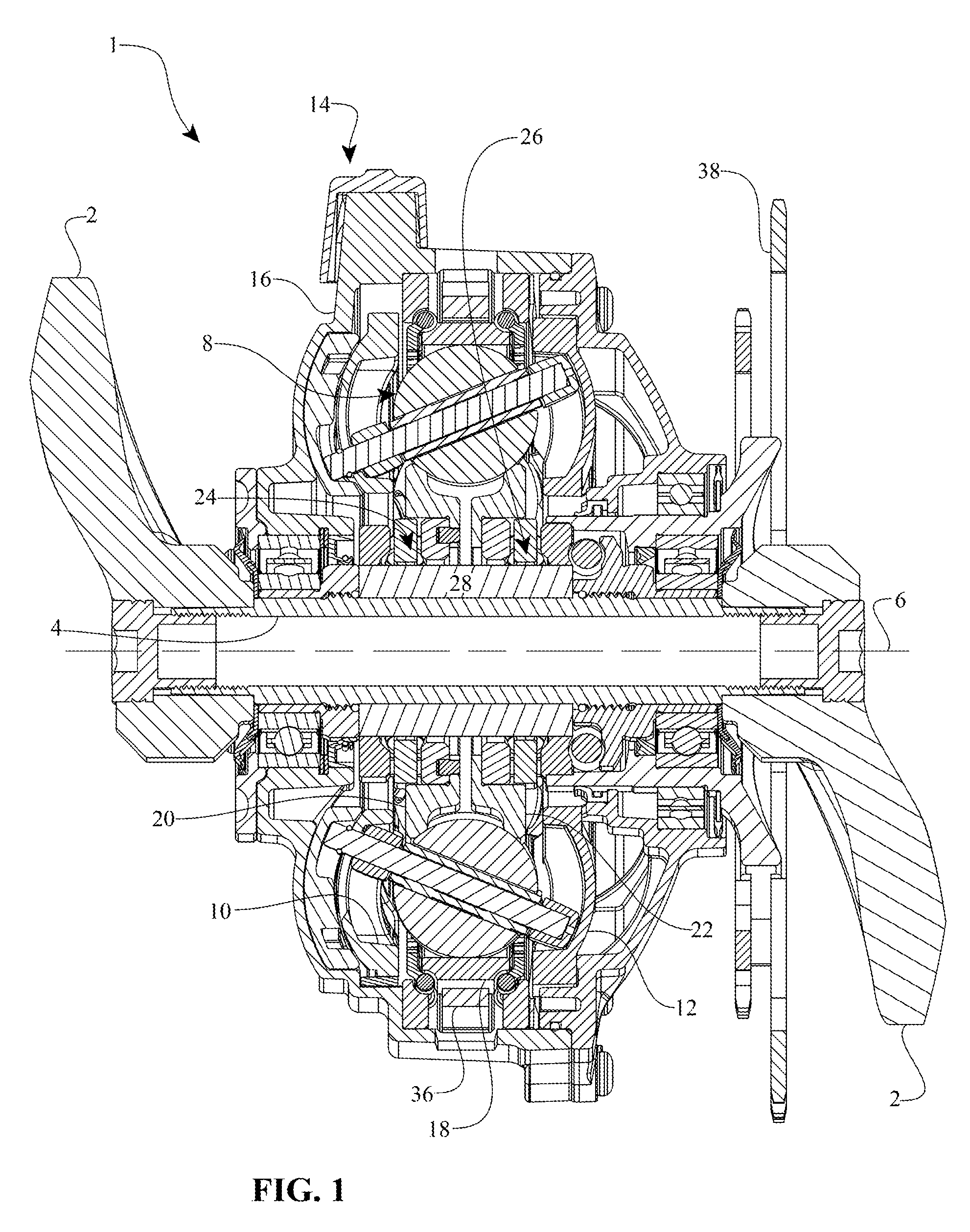
FIG. 1 is cross sectional view of a CVT adapted to couple to cranks of a bicycle.
FIG. 2 is a partial cross-sectional perspective view of the CVT of FIG. 1 coupled to an electric drive motor assembly.
FIG. 3 is a perspective view of an electric drivetrain having the CVT of FIG. 1.
FIG. 4 is a cross-sectional view of an embodiment of an integrated electric motor and CVT.
FIG. 5A is a cross-sectional perspective view of the CVT of FIG. 1.
FIG. 5B is a perspective view of a carrier plate and shifter assembly that can be used with the CVTs of FIG. 1 and/or FIG. 4.
FIG. 6 is a schematic illustration of a bicycle having an electric motor and CVT coupled to a crank.
FIG. 7 is a schematic illustration of a bicycle having an electric motor coaxial with a crank of the bicycle and a CVT coupled to and offset from the crank.
FIG. 8 is a schematic illustration of a bicycle having an electric motor coaxial with, and coupled to, a CVT, the motor and CVT coaxial with and coupled to a crank of the bicycle.
FIG. 9 is a schematic illustration of a bicycle having an electric motor coupled to, and offset from, a crank of the bicycle, and a continuously variable transmission coaxial with, and coupled to, the crank.
FIG. 10 is a schematic illustration of a bicycle having an electric motor coaxial with, and coupled to a CVT, the CVT coaxial with and coupled to a rear wheel of the bicycle.
FIG. 11 is an exploded perspective view of a pair of carrier members and a shifting mechanism.
FIG. 12 is a cross-sectional perspective view of a transmission including a planetary gear set.
FIG. 13 schematically depicts a portion of a transmission including two stator plates and a rotatable gear structure in contact with each of the carrier members.
FIG. 14 shows a perspective view of a multi-diameter gear structure.
FIG. 15 shows an opposite perspective view of the multi-diameter gear structure of FIG. 14.
DETAILED DESCRIPTION OF CERTAIN EMBODIMENTS
Certain embodiments will be described now with reference to the accompanying figures, wherein like numerals refer to like elements throughout. The terminology used in the descriptions below is not to be interpreted in any limited or restrictive manner simply because it is used in conjunction with detailed descriptions of certain specific embodiments of the disclosure. Furthermore, embodiments disclosed herein can include several novel features, no single one of which is solely responsible for its desirable attributes or which is essential to practicing the embodiments described. Certain CVT and infinitely variable transmission (IVT) embodiments described here are generally related to the type disclosed in U.S. Pat. Nos. 6,241,636; 6,419,608; 6,689,012; 7,011,600; 7,166,052; 7,632,203; 7,914,029; 8,321,097; 8,376,903; 8,360,917; 8,393,989; U.S. Patent application Ser. Nos. 11/243,484; 11/543,311; 12/198,402; 12/251,325; and Patent Cooperation Treaty Patent Application Nos. PCT/US2007/023315; PCT/IB2006/054911; PCT/US2008/068929; and PCT/US2008/074496. The entire disclosure of each of these patents and patent applications is hereby incorporated by reference herein.
As used here, the terms "operationally connected," "operationally coupled," "operationally linked," "operably connected," "operably coupled," "operably linked," and like terms, refer to a relationship (mechanical, linkage, coupling, etc.) between elements whereby operation of one element results in a corresponding, following, or simultaneous operation or actuation of a second element. It is noted that in using these terms to describe inventive embodiments, specific structures or mechanisms that link or couple the elements are typically described. However, unless otherwise specifically stated, when one of said terms is used, the term indicates that the actual linkage or coupling may take a variety of forms, which in certain instances will be readily apparent to a person of ordinary skill in the relevant technology.
For description purposes, the term "radial" is used here to indicate a direction or position that is perpendicular relative to a longitudinal axis of a transmission or variator and extends radially outward from a center point when describing a disc. The term "axial" as used here refers to a direction or position along an axis that is parallel to a main or longitudinal axis of a transmission or variator. For clarity and conciseness, at times similar components are labeled similarly.
It should be noted that reference herein to "traction" does not exclude applications where the dominant or exclusive mode of power transfer is through "friction." Without attempting to establish a categorical difference between traction and friction drives here, generally these may be understood as different regimes of power transfer. Traction drives usually involve the transfer of power between two elements by shear forces in a thin fluid layer trapped between the elements. The fluids used in these applications usually exhibit traction coefficients greater than conventional mineral oils. The traction coefficient (.mu.) represents the maximum available traction forces which would be available at the interfaces of the contacting components and is a measure of the maximum available drive torque. Typically, friction drives generally relate to transferring power between two elements by frictional forces between the elements. For the purposes of this disclosure, it should be understood that the CVTs and IVTs described herein may operate in both tractive and frictional applications. For example, in the embodiment where an IVT is used for a bicycle application, the IVT can operate at times as a friction drive and at other times as a traction drive, depending on the torque and speed conditions present during operation.
Embodiments of the disclosure can be related to the control of a variator using generally spherical planets each having a tiltable axis of rotation (sometimes referred to here as a "planet axis of rotation") that can be adjusted to achieve a desired ratio of input speed to output speed during operation. In some embodiments, adjustment of the axis of rotation involves angular misalignment of the planet axis in a first plane in order to achieve an angular adjustment of the planet axis of rotation in a second plane, thereby adjusting the speed ratio of the variator. The angular misalignment in the first plane is referred to here as "skew" or "skew angle." This type of variator control is generally described in U.S. patent application Ser. Nos. 12/198,402 and 12/251,325. The entire disclosure of each of these patent applications is hereby incorporated by reference herein. In some embodiments, a control system coordinates the use of a skew angle to generate forces between certain contacting components in the variator that will tilt the planet axis of rotation in the second plane. The tilting of the planet axis of rotation adjusts the speed ratio of the variator. It should be noted that the embodiments disclosed herein may be implemented using other known methods for shifting a variator. Some embodiments build upon the improvements disclosed in U.S. Pat. No. 7,914,029, the entire disclosure of which is incorporated herein by reference.
Embodiments of a CVT, and components and control methods thereof, will be described now with reference to FIGS. 1-15. FIG. 1 shows a CVT 1 that can be used in many applications including, but not limited to, automobiles, light electrical vehicles, hybrid human-, electric-, or internal combustion powered vehicles, industrial equipment, wind turbines, etc. Any technical application that requires modulation of mechanical power transfer between a power input and a power sink (for example, a load) can implement embodiments of the CVT 1 in its power train.
Referring to FIG. 1, in some embodiments a CVT 1 can be operably coupled to a set of bicycle cranks 2. The bicycle cranks 2 are coupled to a crankshaft 4 configured to rotate about a crank axis 6. The CVT 1 is provided with a number of spherical traction planet assemblies 8, including traction planets, arranged angularly about a longitudinal axis. In this embodiment, the longitudinal axis of the CVT 1 is coaxial with the crank axis 6. In other embodiments, the longitudinal axis of the CVT 1 can be radially offset from the crank axis 6. Each traction planet assembly 8 is supported by first and second carrier members 10, 12, respectively. In some implementations, the second carrier member 12 is operably coupled to the first carrier member 10, and the first and second carrier members 10, 12 are coupled to each traction planet. The second carrier member 12 can include a plurality of radial slots formed in the second carrier member 12 and arranged angularly about the longitudinal axis of the CVT 1. In some embodiments, the first carrier member 10 is operably coupled to a control mechanism, which may include shifter 14. The shifter 14 is located radially outward of the traction planet assemblies 8 and is operably coupled to a transmission housing 16. In some embodiments, the CVT 1 is provided with a traction ring 18 in contact with, and radially outward of each traction planet assembly 8. Each traction planet assembly 8 is in contact with first and second sun members 20, 22, respectively. The first and second sun members 20, 22 are located radially inward of the traction ring 18. The first sun member 20 is operably coupled to a first axial force generator 24. In some embodiments, the first axial force generator 24 includes a set of rollers on cam ramps that are adapted to provide axial force dependent upon torque and/or speed during operation of the CVT 1. The second sun member 22 can be operably coupled to a second axial force generator 26. In some embodiments, a torque sensor 28 is coupled to the crankshaft 4 and the first axial force generator 24.
Turning now to FIGS. 2 and 3, and still referring to FIG. 1, in some embodiments, the CVT 1 can be operably coupled to an electric motor 30 via a gear set 32. The gear set 32 can be provided with a drive gear 34 in contact with a ring gear 36. In some embodiments, the ring gear 36 can be fixedly attached to the traction ring 18. In other embodiments, the ring gear 36 is coupled to the traction ring 18 through a one-way roller clutch that enables a user to pedal the bicycle with the motor off. In some embodiments, the ring gear 36 is located on the interior of the housing 16 while the drive gear 34 is located substantially on the exterior of the housing 16 and couples to the ring gear 36 through an opening in the housing 16. In some embodiments, the motor 30 has a drive axis 31 that is radially offset from, and parallel to, the crank axis 6. In other embodiments, the drive axis 31 of the motor 30 and the crank axis 6 of the crankshaft 4 are coaxial.
During operation of a bicycle equipped with the CVT 1 and the motor 30, a user applies a rotational power input to the crankshaft 4 via the cranks 2. The crankshaft 4 delivers power to the traction planet assemblies 8 via the first sun member 20. The motor 30 applies a rotational power input to the traction ring 18 through the ring gear 36 and the gear set 32. The CVT 1 combines the power from the two sources and delivers an output power to a sprocket 38 through the second sun member 22. A change in the ratio of the input to output can be achieved by varying the ratio of the CVT 1. The ratio of the CVT 1 is adjusted by a relative rotation of the first carrier member 10 with respect to the second carrier member 12. In some embodiments, the first carrier member 10 is rotatable and the second carrier member 12 is fixed to the housing 16. In some embodiments, the first carrier member 10 is rotatable in relation to the second carrier member 12, and second carrier member 12 is rotatable in relation to the fixed housing 16. A mechanism can be configured to control the relationship between the first and second carrier members 10, 12. The mechanism is rotatable in relation to the fixed housing 16, and rotatable in relation to the first carrier member 10 at a different ratio than it is rotatable in relation to the second carrier member 12.
Referring now to FIGS. 4, 5A, and 5B, in some embodiments an integrated electrical drivetrain 40 can be mounted on the bottom bracket of a bicycle and operably coupled to a set of cranks 42. The cranks 42 couple to a crankshaft 44 configured to rotate about a crank axis, which in the illustrated embodiment is coaxial with a longitudinal axis 46. In some embodiments, the drivetrain 40 includes a motor 48 having a drive axis and a CVT 50 having a longitudinal axis 46. In the illustrated embodiment, the drive axis of the motor 48 is also coaxial with the longitudinal axis 46 of the CVT. The motor 48 and the CVT 50 are substantially enclosed by a housing 51. The CVT 50 may be substantially similar to the CVT 1. For description purposes, only the differences between CVT 50 and CVT 1 will be addressed. In some embodiments, the motor 48 is operably coupled to the crankshaft 44. The crankshaft 44 is adapted to receive a rotational input power from the cranks 42 and the motor 48. In some embodiments, the motor 48 couples to the crankshaft 44 through a one-way roller clutch. The input power is transferred to the CVT 50 through a first axial force generator assembly 52 and a first sun member 54. The CVT 50 can be provided with a torque sensor 58 operably coupled to the first axial force generator assembly 52. In some embodiments, the CVT 50 has a second sun member 60 in contact with each traction planet assembly 8. The second sun member 60 is operably coupled to an output driver 62 through a second axial force generator. The output driver 62 couples to a drive sprocket 64.
During operation of the drivetrain 40, a rotational power input is transmitted to the crankshaft 44 from the cranks 42. A second source of rotational power can be transmitted to the crankshaft 44 from the motor 48. The power from each source is transmitted to the first sun member 54 through the torque sensor 58 and the first axial force generator assembly 52. The ratio of input torque and/or speed to output torque and/or speed can be adjusted by tilting the rotational axis of the traction planet assemblies 8. In some embodiments, the traction planet assemblies 8 can be tilted by relative rotation of a first carrier member 66 with respect to a second carrier member 68. Modulated power can be transmitted out of the CVT 50 through the second sun member 60. The second sun member 60 transmits power to the sprocket 64 through the output driver 62.
It should be noted that the motor 48 can be coupled to any component of the CVT 50 Likewise, the crankshaft 44 can be operably coupled to any component of the CVT 50. Combinations of input power couplings and output power couplings are discussed in U.S. Pat. No. 7,011,600, which is hereby incorporated by reference herein. In some embodiments, the integrated motor or generator electrical components described in U.S. Pat. No. 7,727,101 are incorporated.
Turning now to FIGS. 5A and 5B, in some embodiments, the shifter 14 can be similar to the shifters described in U.S. Pat. No. 8,360,917, or that of International Publication No. WO 2010/017242 A1, the entire disclosures of which are hereby incorporated by reference herein. The shifter 14 can be provided with cable channels 70 that can receive control cables from the bicycle (not shown). The shifter 14 couples to a shift drum 72 with splines 74. The splines 74 engage mating splines 76 provided on the shifter 14. In some embodiments, an end of the shift drum 74 has an eccentric, offset follower 78. The follower 78 can be received in the carrier member 10, for example, in a slot 80. During operation, the shifter 14 can be used to rotate the shift drum 72 to thereby guide the follower 78 in the slot 80 resulting in a rotation of the carrier member 10. The carrier member 10 is provided with a number of radially offset slots 82. In some embodiments, the radially offset slots 82 have a parallel but linear offset from a radial centerline of the first carrier member 10. The radial centerline of the first carrier member 10 is perpendicular to the longitudinal axis 6. A coordinate system having a z-axis corresponding to the longitudinal axis 6, a y-axis corresponding to the radial centerline, and an x-axis perpendicular to the y-axis and z-axis can be used to describe the location of the radially offset slots 82 on the first carrier member 10. The radially offset slots 82 lie in a plane formed by the x-axis and y-axis. Each traction planet is adapted to tilt in a plane formed by the y-axis and z-axis. Additional details are provided in U.S. patent application Ser. No. 12/198,402 (corresponding to U.S. Publication No. 2010/0056322) and U.S. Pat. No. 8,167,759, the disclosures of which are incorporated by reference herein in their entirety. In some embodiments, the second carrier member 12 may include slots that are radially offset from its radii as well.
In some embodiments, the second carrier member 12, for example, can be coupled to a second shift drum (not shown) that is substantially similar to the shift drum 72. In other embodiments, a lever mechanism can be arranged to rotate either or both of the first and second carrier members 10, 12 to thereby facilitate a change in ratio of the CVT.
Referring now to FIG. 6, in some embodiments, a bicycle 90 can be provided with a bottom bracket crankshaft 92 and sprocket 94. The crankshaft 92 is operably coupled to an electric drivetrain having a motor 96 and a CVT 98. In some embodiments, the motor 96 has a drive axis that is radially offset from a crank axis of the crankshaft 92. The CVT 98 has a longitudinal axis that is radially offset from the crank axis of the crankshaft 92.
Referring now to FIG. 7, in some embodiments a bicycle 100 can be provided with a bottom bracket crankshaft 102 and sprocket 104. The crankshaft 102 is operably coupled to an electric drivetrain having a motor 106 and a CVT 108. In some embodiments, a drive axis of the motor 106 and a crank axis of the crankshaft 102 are coaxial. The CVT 108 has a longitudinal axis that is radially offset from the crank axis of the crankshaft 102.
Referring now to FIG. 8, in some embodiments a bicycle 110 can be provided with a bottom bracket crankshaft 112 and sprocket 114. The crankshaft 112 is operably coupled to an electric drivetrain having a motor 116 and a CVT 118. In some embodiments, the motor 116 has a drive axis that is radially offset from a crank axis of the crankshaft 112. A longitudinal axis of the CVT 118 and a crank axis of the crankshaft 112 are coaxial.
Referring now to FIG. 9, in some embodiments a bicycle 120 can be provided with a bottom bracket crankshaft 122 and sprocket 124. The crankshaft 122 is operably coupled to an electric drivetrain having a motor 126 and a CVT 128. In some embodiments, a drive axis of the motor 126 and a crank axis of the crankshaft 122 are coaxial. A longitudinal axis of the CVT 128 and a crank axis of the crankshaft 122 are coaxial.
Referring now to FIG. 10, in some embodiments a bicycle 130 can be provided with a bottom bracket crankshaft 132 and sprocket 134. The crankshaft 132 is operably coupled to an electric drivetrain having a motor 136 and a CVT 138 that is coupled to a rear wheel 140 of the bicycle 130.
In some embodiments, the electric motor 30 and/or 48 can be in electrical communication with a control system having an electronic controller, a number of sensors, a source of electrical power, and appropriate wiring and electrical hardware such as those described in U.S. Pat. Nos. 7,343,236 and 7,885,747 and European Patent No. 1,984,637, which are hereby incorporated by reference herein. The electronic controller can be programmed with an algorithm configured to provide automatic adjustment of the motor 30, for example. In some embodiments, the electronic controller can be programmed with an algorithm configured to provide automatic adjustment of the CVT 1, for example. As an illustrative example, the controller can receive an input associated with a target user pedaling speed and determine a speed of the bicycle. In some embodiments, a PID (proportional-integral-derivative) controller and algorithm can be employed in the control system. For example, the controller can be configured to adjust the transmission ratio based at least in part on a reading from a torque sensor. As disclosed herein, a controller may refer to a device or system for implementing preferred functionality. Embodiments of a controller or portions thereof may be integrated with other components or be separate. For example, in some embodiments, a controller may be a stand-alone device that is communicatively coupled to other components. Wired or wireless communications may be possible for communicatively coupling a controller to other components. Wireless communications may be via Bluetooth, any 802.11 compliant protocol or any other wireless protocol known to those of skill in the art. Some embodiments utilize wireless communications between a controller and the shift actuator. A portion of logic may be stored in memory associated with a CVT and a portion of logic may be implemented by a controller communicatively coupled to the CVT. For example, electronic devices such as smart phones have memory and processors available to store and execute logic, and may be mounted or otherwise associated with a CVT to allow for easy access and use by a user.
In some embodiments, the user of the bicycle can manually adjust the transmission ratio with, for example, the shifter 14. In such embodiments, the electronic controller can be programmed to control the motor 30 and provide additional power assistance to the rider based on a torque sensor reading. The torque assistance enables the rider to maintain a cadence and/or speed of the bicycle in the presence of varying terrain or other factors affecting operating condition of the bicycle. In some embodiments, the torque from the motor 30 is varied based at least in part on a command from the electronic controller.
In some embodiments, a method of automatically controlling the CVT 1 and/or the motor 30, for example, involves receiving an input associated with a target user pedaling speed, determining a speed of the bicycle, and determining a target transmission ratio based at least in part on the target user pedaling speed and the determined speed of the bicycle. A method can also include adjusting a transmission ratio of the transmission to be substantially equal to the target transmission ratio. In some embodiments, the method further includes the step of determining an encoder position associated with the target user pedaling speed. In some embodiments, the controller can adjust a transmission ratio that can include commanding an actuator to move to the determined encoder position. In some embodiments, adjusting a shift drum includes the step of rotating a shift rod about a longitudinal axis of the transmission.
A method of automatically controlling a CVT and/or a motor may include receiving an input associated with a target user pedaling speed, determining a speed of the bicycle, and based upon the target user pedaling speed and the determined speed of the bicycle, adjusting a speed ratio of the bicycle to maintain a user pedaling speed within a band of the target user pedaling speed. In some embodiments, the band is the target user pedaling speed plus or minus 10 revolutions-per-minute (rpm). In some embodiments, the band is the target user pedal speed in the range of +/-2 rpm to about +/-5 rpm. In some embodiments, adjusting a speed ratio of the bicycle includes the step of determining an encoder position associated with the target user pedaling speed and the determined speed of the bicycle. In some embodiments, adjusting a speed ratio of the bicycle includes the step of commanding an actuator to move to the determined encoder position. In some embodiments, adjusting a speed ratio of the bicycle includes the step of adjusting a shift rod of the transmission. In some embodiments, adjusting the shift rod includes the step of rotating the shift rod about a longitudinal axis of the transmission.
A method of automatically controlling a CVT and/or a motor may involve providing an input associated with a target user pedaling speed, determining a speed of the bicycle, and identifying a target encoder position associated with the speed of the bicycle. A method can further include actuating a servo to achieve the target encoder position. In some embodiments, actuating a servo includes the step of adjusting a shift rod of the transmission. In some embodiments, identifying the target encoder position includes generating a data structure. In some embodiments, generating a data structure includes the step of recording an encoder position. In some embodiments, generating a data structure includes the steps of recording an input speed and recording an output speed. In some embodiments, a method includes the step of determining a speed ratio based at least in part on the input speed and the output speed. In some embodiments, a method includes the step of recording the speed ratio.
In some embodiments, a control system for the electrical drivetrain 40, for example, can include a speed sensor configured to detect a speed of the bicycle, a processor configured to receive input from the speed sensor, and a data input interface configured to provide cadence data to the processor, the cadence data indicative of an input pedaling speed. The system may include a memory in communication with the processor, the memory having stored therein one or more maps correlating bicycle speeds with speed ratios. In some embodiments, the system includes a logic module in communication with the processor, the logic module configured to cooperate with the processor to determine from the maps a target speed ratio based on a bicycle speed and an input pedaling speed. In some embodiments, the system has an actuator in communication with the processor, the actuator configured to adjust a speed ratio of the transmission to be substantially equal to the determined target speed ratio. In some embodiments, the control unit includes at least one of a processor, an application specific integrated circuit, or a programmable logic array. The actuator is operably coupled to a shift rod of the transmission, the shift rod configured to adjust the speed ratio of the transmission. The data input interface can include a display and at least one button. The system can include a position sensor configured to provide an indication of a position of the actuator. The data structures can include a speed ratio data structure and a bicycle speed data structure. The system can have a power source configured to supply a power to the actuator. In some embodiments, the power source is a dynamo. In some embodiments, the actuator is operably coupled to a shift rod of the transmission.
In some embodiments, a control system for use with a bicycle equipped with the CVT 1 and/or the electric drivetrain 40, for example, has a speed sensor configured to detect a speed of the bicycle. The system has a processor configured to receive input from the speed sensor. In some embodiments, the system includes a data input interface configured to provide cadence data to the processor. The cadence data is indicative of an input pedaling speed. The system can include a memory in communication with the processor. In some embodiments, the memory has stored therein one or more maps correlating bicycle speeds with speed ratios. The system includes a logic module in communication with the processor. The logic module is configured to cooperate with the processor to determine from the maps a target speed ratio based on a bicycle speed and an input pedaling speed. The system can also include an actuator in communication with the processor. The actuator is configured to adjust a speed ratio of the transmission to be substantially equal to the determined target speed ratio. In some embodiments, the data input interface includes a display and at least one button. In some embodiments, the data input interface is mounted on a handlebar of the bicycle. The bicycle can include a position sensor configured to provide an indication of a position of the actuator. In some embodiments, the data structures have a speed ratio data structure and a bicycle speed data structure. In other embodiments, the ball-planetary transmission includes a shift rod, the shift rod operably coupled to the actuator.
At planet tilt angles other than zero degrees, there exists a difference in the magnitude of the opposed torques on the two carrier members, and a net torque may develop on the two carrier members. If the resulting net position of the two carrier members changes when the relative position of the two carrier members changes, then either work is being done to the two carrier members or work is being done by the two carriers. Embodiments disclosed herein may utilize the work to modify a force-position relationship of a control actuator.
FIG. 11 is an exploded perspective view of a pair of carrier members, also referred to as stator plates (alternately referred to as carrier plates) and a shifting mechanism which can be used to advance or retard the rotation of one of the stator plates with respect to the other stator plate.
A zero plane may be defined as a plane in which lies a main axis of the CVT and at least one planet axis when that planet axis is parallel to the main axis. In the illustrated embodiment, the shifting mechanism includes two cam surfaces, one on each side of the shifting mechanism, and an outwardly extending spindle about which the shifting mechanism can be configured to rotate. Each stator plate includes an aperture configured to receive one of the cam surfaces. One of the cam surfaces may be located radially outward or inward of the other cam surface relative to the axis of rotation of the shifting mechanism. In some embodiments, an axis of eccentricity of a first cam surface may be angularly offset from an axis of eccentricity of a second cam surface. As a result of one or more of the difference in the magnitudes of eccentricity or an angular offset with respect to the axes of eccentricity, rotation of the shifting mechanism may induce a greater amount of rotation in the stator plate in contact with the radially outward cam surface than in the stator plate in contact with the radially inward cam surface. In some embodiments, one or more axes of eccentricity may be angularly offset with respect to the zero plane.
A shifting mechanism such as that depicted in FIG. 11 can sum the torque force experienced by both stator plates, thereby reducing the overall shift force required to change the position of the shifting mechanism to initiate a shift of the transmissions described herein or other similar transmissions.
In some embodiments, the cam surfaces may be spring loaded or otherwise deformable in response to increased load. For example, in one particular embodiment, at least a portion of the cam surface may be a resilient band of material which deforms in response to an applied load. By providing a dynamic cam surface whose shape is at least partially dependent upon the load, some passive feedback control of the relative rotation of the stator plates to one another may be provided, which can adjust the speed ratio in response to the load experienced by the stator plates and the cam surface. In such embodiments, the relative position of the two stator plates may be dependent on the applied load as well as the position of the shifting mechanism. While a rotating member with cam surfaces is shown to sum the forces experienced by the stator plates based upon a condition of the transmission, the summing and shifting can also be performed by levers, offset gears or other known structures, in each case that are operationally coupled to the stator plates as well.
FIG. 12 is a cross-sectional perspective view of a transmission including a planetary gear set. A worm screw may be provided to shift the position of a shifting mechanism of the embodiments described herein and such as that shown in FIG. 11. Although the illustrated implementation depicts a worm screw which can be used to change the position of the shifting mechanism, or a stator plate, any suitable control system or apparatus may be used to control the position of the shifting mechanism or stator plates. As illustrated in FIG. 12, the planetary gear set can be used as part of the power path to change the speed and alter the torque applied to the transmission or the motor of the embodiments described herein, or it can be used to distribute torque throughout the various components in the transmission, as desired to manage the amount of torque passed through the variable path of the transmission. In some embodiments, multiple paths for power to pass are present and it may be advantageous to vary the amount of power that is transferred through the planets of the transmission to improve efficiency, to manage torque and the associated stress or for other commonly known reasons. For example, the planetary gear set can be used to step up the speed of an input component and reduce the torque going to the generator.
In addition, a motor may also be integrated with the planetary gear set. As described in greater detail in U.S. Pat. No. 7,632,203, the disclosure of which is incorporated by reference herein in its entirety, the integration of a motor and a transmission can also advantageously be used to alter the operating conditions of the motor and enhance the performance of the motor. For example, stepping up the speed of certain motor components relative to other components can increase the resultant flux characteristics and enhance motor performance. Additional examples of motor types, motor configurations, and the beneficial effects which can be achieved by integrating a motor with a transmission including a planetary gear set are described in U.S. Pat. No. 7,632,203.
FIGS. 13-15 show a method of controlling the relative rotation of two carrier members, such as carrier members 66, 68 depicted in FIG. 4. FIG. 13 schematically depicts a portion of a transmission including carrier members 66, 68 and a rotatable gear structure 1300 in contact with each of the stator plates and rotatable about axis 1305. Gear structure 1300 includes a first section 1310 having a first diameter and in contact with first carrier member 66, and a second section 1320 having a second diameter and in contact with second carrier member 68. Because of the differences in diameter of the two gear sections, the gear structure can control the relative rates of rotation of first and second carrier members 66, 68, while still summing the reaction forces of the two carrier members to reduce overall shift force required to adjust the tilt angle of the ball axles of the transmissions described herein.
FIG. 14 shows a perspective view of a multi-diameter gear structure, such as the one described above with respect to FIG. 13, shown here in contact with a toothed section of a single plate. In particular, a first portion of the multi-diameter gear structure, having a larger diameter than the remainder of the structure, is in contact with a toothed section of a first plate. A second portion of the multi-diameter gear structure, with a smaller diameter, can be in contact with a toothed section of a second plate (see FIG. 15), not shown in FIG. 14 for the sake of clarity.
FIG. 15 shows an opposite perspective view of the multi-diameter gear structure of FIG. 14, shown here in contact with two plates. The narrower portion of the multi-diameter gear structure (not visible in FIG. 14) is in contact with a toothed portion of the rear plate, while the thicker portion of the multi-diameter gear structure is in contact with a toothed portion of the front plate. As described above with respect to FIG. 13, the differences in diameter between the geared sections of the multi-diameter gear structure control the relative amount of rotation between the two plates.
Those of skill will recognize that the various illustrative logical blocks, modules, circuits, and algorithm steps described in connection with the embodiments disclosed herein, including with reference to the transmission control systems described herein, for example, may be implemented as electronic hardware, software stored on a computer readable medium and executable by a processor, or combinations of both. To clearly illustrate this interchangeability of hardware and software, various illustrative components, blocks, modules, circuits, and steps have been described above generally in terms of their functionality. Whether such functionality is implemented as hardware or software depends upon the particular application and design constraints imposed on the overall system. Skilled artisans may implement the described functionality in varying ways for each particular application, but such implementation decisions should not be interpreted as causing a departure from the scope of the present disclosure. For example, various illustrative logical blocks, modules, and circuits described in connection with the embodiments disclosed herein may be implemented or performed with a general purpose processor, a digital signal processor (DSP), an application specific integrated circuit (ASIC), a field programmable gate array (FPGA) or other programmable logic device, discrete gate or transistor logic, discrete hardware components, or any combination thereof designed to perform the functions described herein. A general purpose processor may be a microprocessor, but in the alternative, the processor may be any conventional processor, controller, microcontroller, or state machine. A processor may also be implemented as a combination of computing devices, e.g., a combination of a DSP and a microprocessor, a plurality of microprocessors, one or more microprocessors in conjunction with a DSP core, or any other such configuration. Software associated with such modules may reside in RAM memory, flash memory, ROM memory, EPROM memory, EEPROM memory, registers, a hard disk, a removable disk, a CD-ROM, or any other suitable form of storage medium known in the art. An exemplary storage medium is coupled to the processor such that the processor can read information from, and write information to, the storage medium. In the alternative, the storage medium may be integral to the processor. The processor and the storage medium may reside in an ASIC. For example, in some embodiments, a controller for the CVT 1 comprises a processor (not shown).
The foregoing description details certain embodiments of the disclosure. It will be appreciated, however, that no matter how detailed the foregoing appears in text, the disclosure can be practiced in many ways. As is also stated above, it should be noted that the use of particular terminology when describing certain features or aspects of the disclosure should not be taken to imply that the terminology is being re-defined herein to be restricted to including any specific characteristics of the features or aspects of the disclosure with which that terminology is associated.
One or more embodiments described above can be claimed as follows, but this list is not exhaustive and the description contains other embodiments.
* * * * *
D00000
D00001
D00002
D00003
D00004
D00005
D00006
D00007
D00008
XML
uspto.report is an independent third-party trademark research tool that is not affiliated, endorsed, or sponsored by the United States Patent and Trademark Office (USPTO) or any other governmental organization. The information provided by uspto.report is based on publicly available data at the time of writing and is intended for informational purposes only.
While we strive to provide accurate and up-to-date information, we do not guarantee the accuracy, completeness, reliability, or suitability of the information displayed on this site. The use of this site is at your own risk. Any reliance you place on such information is therefore strictly at your own risk.
All official trademark data, including owner information, should be verified by visiting the official USPTO website at www.uspto.gov. This site is not intended to replace professional legal advice and should not be used as a substitute for consulting with a legal professional who is knowledgeable about trademark law.