Electronic safe door unlatching operations
Kleve , et al.
U.S. patent number 10,323,442 [Application Number 14/696,749] was granted by the patent office on 2019-06-18 for electronic safe door unlatching operations. This patent grant is currently assigned to Ford Global Technologies, LLC. The grantee listed for this patent is Ford Global Technologies, LLC. Invention is credited to Lisa Therese Boran, Ronald Patrick Brombach, Laura Viviana Hazebrouck, Robert Bruce Kleve, Howard Paul Tsvi Linden, John Thomas Ricks, John Robert Van Wiemeersch, Jim Michael Weinfurther.


| United States Patent | 10,323,442 |
| Kleve , et al. | June 18, 2019 |
Electronic safe door unlatching operations
Abstract
A powered latch system for motor vehicles includes at least one powered latch that can be controlled based, at least in part, on vehicle operating conditions. The system may be configured to control unlatching of the vehicle doors utilizing data relating to the vehicle speed and/or the existence of a crash event. The powered latch system can be configured as required for various vehicles, and to accommodate specific operating requirements with respect to child locks in various geographic jurisdictions.
| Inventors: | Kleve; Robert Bruce (Ann Arbor, MI), Ricks; John Thomas (Taylor, MI), Weinfurther; Jim Michael (Farmington Hills, MI), Van Wiemeersch; John Robert (Novi, MI), Brombach; Ronald Patrick (Plymouth, MI), Hazebrouck; Laura Viviana (Birmingham, MI), Boran; Lisa Therese (Northville, MI), Linden; Howard Paul Tsvi (Southfield, MI) | ||||||||||
|---|---|---|---|---|---|---|---|---|---|---|---|
| Applicant: |
|
||||||||||
| Assignee: | Ford Global Technologies, LLC
(Dearborn, MI) |
||||||||||
| Family ID: | 54538076 | ||||||||||
| Appl. No.: | 14/696,749 | ||||||||||
| Filed: | April 27, 2015 |
Prior Publication Data
| Document Identifier | Publication Date | |
|---|---|---|
| US 20150330115 A1 | Nov 19, 2015 | |
Related U.S. Patent Documents
| Application Number | Filing Date | Patent Number | Issue Date | ||
|---|---|---|---|---|---|
| 14280035 | May 16, 2014 | 10119308 | |||
| 14276415 | May 13, 2014 | ||||
| Current U.S. Class: | 1/1 |
| Current CPC Class: | E05B 77/54 (20130101); E05B 77/48 (20130101); E05B 81/76 (20130101); E05B 81/14 (20130101); Y10T 292/1047 (20150401) |
| Current International Class: | E05B 77/48 (20140101); E05B 81/76 (20140101); E05B 77/54 (20140101); E05B 81/14 (20140101) |
| Field of Search: | ;292/201,216 |
References Cited [Referenced By]
U.S. Patent Documents
| 2229909 | January 1941 | Wread |
| 2553023 | May 1951 | Walters |
| 3479767 | November 1969 | Gardner et al. |
| 3605459 | September 1971 | Van Dalen |
| 3751718 | August 1973 | Hanchett |
| 3771823 | November 1973 | Schnarr |
| 3854310 | December 1974 | Paull |
| 3858922 | January 1975 | Yamanaka |
| 4193619 | March 1980 | Jeril |
| 4206491 | June 1980 | Ligman et al. |
| 4425597 | January 1984 | Schramm |
| 4457148 | July 1984 | Johansson et al. |
| 4640050 | February 1987 | Yamagishi et al. |
| 4672348 | June 1987 | Duve |
| 4674230 | June 1987 | Takeo et al. |
| 4674781 | June 1987 | Reece et al. |
| 4702117 | October 1987 | Tsutsumi et al. |
| 4848031 | June 1989 | Yamagishi et al. |
| 4858971 | August 1989 | Haag |
| 4889373 | December 1989 | Ward et al. |
| 4929007 | May 1990 | Bartczak et al. |
| 5018057 | May 1991 | Biggs et al. |
| 5056343 | October 1991 | Kleefeldt et al. |
| 5058258 | October 1991 | Harvey |
| 5074073 | December 1991 | Zwebner |
| 5092637 | March 1992 | Miller |
| 5239779 | August 1993 | Deland et al. |
| 5263762 | November 1993 | Long et al. |
| 5297010 | March 1994 | Camarota et al. |
| 5332273 | July 1994 | Komachi |
| 5334969 | August 1994 | Abe et al. |
| 5494322 | February 1996 | Menke |
| 5497641 | March 1996 | Linde et al. |
| 5535608 | July 1996 | Brin |
| 5547208 | August 1996 | Chappell et al. |
| 5551187 | September 1996 | Brouwer et al. |
| 5581230 | December 1996 | Barrett |
| 5583405 | December 1996 | Sai et al. |
| 5613716 | March 1997 | Cafferty |
| 5618068 | April 1997 | Mitsui et al. |
| 5632120 | May 1997 | Shigematsu et al. |
| 5632515 | May 1997 | Dowling |
| 5644869 | July 1997 | Buchanan, Jr. |
| 5653484 | August 1997 | Brackmann et al. |
| 5662369 | September 1997 | Tsuge |
| 5684470 | November 1997 | Deland et al. |
| 5744874 | April 1998 | Yoshida et al. |
| 5755059 | May 1998 | Schap |
| 5783994 | July 1998 | Koopman, Jr. et al. |
| 5802894 | September 1998 | Jahrsetz et al. |
| 5808555 | September 1998 | Bartel |
| 5859479 | January 1999 | David |
| 5895089 | April 1999 | Singh et al. |
| 5896026 | April 1999 | Higgins |
| 5896768 | April 1999 | Cranick et al. |
| 5898536 | April 1999 | Won |
| 5901991 | May 1999 | Hugel et al. |
| 5921612 | July 1999 | Mizuki et al. |
| 5927794 | July 1999 | Mobius |
| 5964487 | October 1999 | Shamblin |
| 5979754 | November 1999 | Martin et al. |
| 5992194 | November 1999 | Baukholt et al. |
| 6000257 | December 1999 | Thomas |
| 6038895 | March 2000 | Menke et al. |
| 6042159 | March 2000 | Spitzley et al. |
| 6043735 | March 2000 | Barrett |
| 6050117 | April 2000 | Weyerstall |
| 6056076 | May 2000 | Bartel et al. |
| 6065316 | May 2000 | Sato et al. |
| 6072403 | June 2000 | Iwasaki et al. |
| 6075294 | June 2000 | Van den Boom et al. |
| 6091162 | July 2000 | Williams, Jr. et al. |
| 6099048 | August 2000 | Salmon et al. |
| 6125583 | October 2000 | Murray et al. |
| 6130614 | October 2000 | Miller |
| 6145918 | November 2000 | Wilbanks, II |
| 6157090 | December 2000 | Vogel |
| 6181024 | January 2001 | Geil |
| 6198995 | March 2001 | Settles et al. |
| 6241294 | June 2001 | Young et al. |
| 6247343 | June 2001 | Weiss et al. |
| 6256932 | July 2001 | Jyawook et al. |
| 6271745 | August 2001 | Anazi et al. |
| 6341448 | January 2002 | Murray |
| 6357803 | March 2002 | Lorek |
| 6361091 | March 2002 | Weschler |
| 6405485 | June 2002 | Itami et al. |
| 6406073 | June 2002 | Watanabe |
| 6441512 | August 2002 | Jakel et al. |
| 6460905 | October 2002 | Suss |
| 6470719 | October 2002 | Franz et al. |
| 6480098 | November 2002 | Flick |
| 6515377 | February 2003 | Uberlein et al. |
| 6523376 | February 2003 | Baukholt et al. |
| 6550826 | April 2003 | Fukushima et al. |
| 6554328 | April 2003 | Cetnar et al. |
| 6556900 | April 2003 | Brynielsson |
| 6602077 | August 2003 | Kasper et al. |
| 6606492 | August 2003 | Losey |
| 6629711 | October 2003 | Gleason et al. |
| 6639161 | October 2003 | Meagher et al. |
| 6640174 | October 2003 | Schondorf et al. |
| 6657537 | December 2003 | Hauler |
| 6659515 | December 2003 | Raymond et al. |
| 6701671 | March 2004 | Fukumoto et al. |
| 6712409 | March 2004 | Monig |
| 6715806 | April 2004 | Arlt et al. |
| 6734578 | May 2004 | Konno et al. |
| 6740834 | May 2004 | Sueyoshi et al. |
| 6768413 | July 2004 | Kemmann et al. |
| 6779372 | August 2004 | Arlt et al. |
| 6783167 | August 2004 | Bingle et al. |
| 6786070 | September 2004 | Dimig et al. |
| 6794837 | September 2004 | Whinnery et al. |
| 6825752 | November 2004 | Nahata et al. |
| 6829357 | December 2004 | Alrabady et al. |
| 6843085 | January 2005 | Dimig |
| 6854870 | February 2005 | Huizenga |
| 6879058 | April 2005 | Lorenz et al. |
| 6883836 | April 2005 | Breay et al. |
| 6883839 | April 2005 | Belmond et al. |
| 6910302 | June 2005 | Crawford |
| 6914346 | July 2005 | Girard |
| 6923479 | August 2005 | Aiyama |
| 6933655 | August 2005 | Morrison et al. |
| 6946978 | September 2005 | Schofield |
| 7005959 | February 2006 | Amagasa |
| 7038414 | May 2006 | Daniels et al. |
| 7055997 | June 2006 | Baek |
| 7062945 | June 2006 | Saitoh et al. |
| 7070018 | July 2006 | Kachouh |
| 7070213 | July 2006 | Willats et al. |
| 7090285 | August 2006 | Markevich et al. |
| 7091823 | August 2006 | Ieda et al. |
| 7091836 | August 2006 | Kachouh et al. |
| 7097226 | August 2006 | Bingle et al. |
| 7106171 | September 2006 | Burgess |
| 7108301 | September 2006 | Louvel |
| 7126453 | October 2006 | Sandau et al. |
| 7145436 | December 2006 | Ichikawa et al. |
| 7158870 | January 2007 | Schondorf et al. |
| 7161152 | January 2007 | Dipoala |
| 7170253 | January 2007 | Spurr et al. |
| 7173346 | February 2007 | Aiyama et al. |
| 7176810 | February 2007 | Inoue |
| 7180400 | February 2007 | Amagasa |
| 7192076 | March 2007 | Ottino |
| 7204530 | April 2007 | Lee |
| 7205777 | April 2007 | Schultz et al. |
| 7221255 | May 2007 | Johnson et al. |
| 7222459 | May 2007 | Taniyama |
| 7248955 | July 2007 | Hein et al. |
| 7263416 | August 2007 | Sakurai et al. |
| 7270029 | September 2007 | Papanikolaou et al. |
| 7325843 | February 2008 | Coleman et al. |
| 7342373 | March 2008 | Newman et al. |
| 7360803 | April 2008 | Parent et al. |
| 7363788 | April 2008 | Dimig et al. |
| 7375299 | May 2008 | Pudney |
| 7399010 | July 2008 | Hunt et al. |
| 7446645 | November 2008 | Steegmann |
| 7576631 | August 2009 | Bingle et al. |
| 7642669 | January 2010 | Spurr |
| 7686378 | March 2010 | Gisler et al. |
| 7688179 | March 2010 | Kurpinski et al. |
| 7707522 | April 2010 | Shoemaker et al. |
| 7747286 | June 2010 | Conforti |
| 7780207 | August 2010 | Gotou |
| 7791218 | September 2010 | Mekky |
| 7926385 | April 2011 | Papanikolaou et al. |
| 7931314 | April 2011 | Nitawaki et al. |
| 7937893 | May 2011 | Pribisic |
| 8028375 | October 2011 | Nakaura et al. |
| 8093987 | January 2012 | Kurpinski et al. |
| 8126450 | February 2012 | Howarter et al. |
| 8141296 | March 2012 | Bem |
| 8141916 | March 2012 | Tomaszewski et al. |
| 8169317 | May 2012 | Lemerand et al. |
| 8193462 | June 2012 | Zanini et al. |
| 8224313 | July 2012 | Howarter et al. |
| 8272165 | September 2012 | Tomioke |
| 8376416 | February 2013 | Arabia, Jr. et al. |
| 8398128 | March 2013 | Arabia et al. |
| 8405515 | March 2013 | Ishihara et al. |
| 8405527 | March 2013 | Chung et al. |
| 8419114 | April 2013 | Fannon |
| 8451087 | May 2013 | Krishnan et al. |
| 8454062 | June 2013 | Rohlfing et al. |
| 8463500 | June 2013 | Cuddihy et al. |
| 8474889 | July 2013 | Reifenberg et al. |
| 8532873 | September 2013 | Bambenek |
| 8534101 | September 2013 | Mette et al. |
| 8544901 | October 2013 | Krishnan et al. |
| 8573657 | November 2013 | Papanikolaou et al. |
| 8584402 | November 2013 | Yamaguchi |
| 8616595 | December 2013 | Wellborn, Sr. et al. |
| 8648689 | February 2014 | Hathaway et al. |
| 8746755 | June 2014 | Papanikolaou et al. |
| 8826596 | September 2014 | Tensing |
| 8833811 | September 2014 | Ishikawa |
| 8903605 | December 2014 | Bambenek |
| 8915524 | December 2014 | Charnesky |
| 8963701 | February 2015 | Rodriguez |
| 8965287 | February 2015 | Lam |
| 9003707 | April 2015 | Reddmann |
| 9076274 | July 2015 | Kamiya |
| 9159219 | October 2015 | Magner et al. |
| 9184777 | November 2015 | Esselink et al. |
| 9187012 | November 2015 | Sachs et al. |
| 9189900 | November 2015 | Penilla et al. |
| 9260882 | February 2016 | Krishnan et al. |
| 9284757 | March 2016 | Kempel |
| 9322204 | April 2016 | Suzuki |
| 9353566 | May 2016 | Miu et al. |
| 9382741 | July 2016 | Konchan et al. |
| 9405120 | August 2016 | Graf |
| 9409579 | August 2016 | Eichin et al. |
| 9416565 | August 2016 | Papanikolaou et al. |
| 9475369 | October 2016 | Sugiura |
| 9481325 | November 2016 | Lange |
| 9493975 | November 2016 | Li |
| 9518408 | December 2016 | Krishnan |
| 9522590 | December 2016 | Fujimoto et al. |
| 9546502 | January 2017 | Lange |
| 9551166 | January 2017 | Patel et al. |
| 9725069 | August 2017 | Krishnan |
| 9777528 | October 2017 | Elie et al. |
| 9797178 | October 2017 | Elie et al. |
| 9834964 | December 2017 | Van Wiemeersch et al. |
| 9845071 | December 2017 | Krishnan |
| 9903142 | February 2018 | Van Wiemeersch et al. |
| 9909344 | March 2018 | Krishnan et al. |
| 9957737 | May 2018 | Patel et al. |
| 2001/0005078 | June 2001 | Fukushima et al. |
| 2001/0030871 | October 2001 | Anderson |
| 2002/0000726 | January 2002 | Zintler |
| 2002/0111844 | August 2002 | Vanstory et al. |
| 2002/0121967 | September 2002 | Bowen et al. |
| 2002/0186144 | December 2002 | Meunier |
| 2003/0009855 | January 2003 | Budzynski |
| 2003/0025337 | February 2003 | Suzuki et al. |
| 2003/0038544 | February 2003 | Spurr |
| 2003/0101781 | June 2003 | Budzynski et al. |
| 2003/0107473 | June 2003 | Pang et al. |
| 2003/0111863 | June 2003 | Weyerstall et al. |
| 2003/0139155 | July 2003 | Sakai |
| 2003/0172695 | September 2003 | Buschmann |
| 2003/0182863 | October 2003 | Mejean et al. |
| 2003/0184098 | October 2003 | Aiyama |
| 2004/0061462 | April 2004 | Bent et al. |
| 2004/0093155 | May 2004 | Simonds et al. |
| 2004/0124708 | July 2004 | Giehler et al. |
| 2004/0195845 | October 2004 | Chevalier |
| 2004/0217601 | November 2004 | Garnault et al. |
| 2005/0057047 | March 2005 | Kachouh |
| 2005/0068712 | March 2005 | Schulz et al. |
| 2005/0216133 | September 2005 | MacDougall et al. |
| 2005/0218913 | October 2005 | Inaba |
| 2006/0056663 | March 2006 | Call |
| 2006/0100002 | May 2006 | Luebke et al. |
| 2006/0186987 | August 2006 | Wilkins |
| 2007/0001467 | January 2007 | Muller et al. |
| 2007/0090654 | April 2007 | Eaton |
| 2007/0115191 | May 2007 | Hashiguchi et al. |
| 2007/0120645 | May 2007 | Nakashima |
| 2007/0126243 | June 2007 | Papanikolaou et al. |
| 2007/0132553 | June 2007 | Nakashima |
| 2007/0170727 | July 2007 | Kohlstrand et al. |
| 2008/0021619 | January 2008 | Steegmann et al. |
| 2008/0060393 | March 2008 | Johansson et al. |
| 2008/0068129 | March 2008 | Ieda et al. |
| 2008/0129446 | June 2008 | Vader |
| 2008/0143139 | June 2008 | Bauer et al. |
| 2008/0202912 | August 2008 | Boddie et al. |
| 2008/0203737 | August 2008 | Tomaszewski et al. |
| 2008/0211623 | September 2008 | Scheurich |
| 2008/0217956 | September 2008 | Gschweng et al. |
| 2008/0224482 | September 2008 | Cumbo et al. |
| 2008/0230006 | September 2008 | Kirchoff et al. |
| 2008/0250718 | October 2008 | Papanikolaou et al. |
| 2008/0296927 | December 2008 | Gisler et al. |
| 2008/0303291 | December 2008 | Spurr |
| 2008/0307711 | December 2008 | Kern et al. |
| 2009/0033104 | February 2009 | Konchan et al. |
| 2009/0033477 | February 2009 | Illium et al. |
| 2009/0145181 | June 2009 | Pecoul et al. |
| 2009/0160211 | June 2009 | Krishnan et al. |
| 2009/0177336 | July 2009 | McClellan et al. |
| 2009/0240400 | September 2009 | Lachapelle et al. |
| 2009/0257241 | October 2009 | Meinke et al. |
| 2010/0007463 | January 2010 | Dingman et al. |
| 2010/0052337 | March 2010 | Arabia et al. |
| 2010/0060505 | March 2010 | Witkowski |
| 2010/0097186 | April 2010 | Wielebski |
| 2010/0175945 | July 2010 | Helms |
| 2010/0235057 | September 2010 | Papanikolaou et al. |
| 2010/0235058 | September 2010 | Papanikolaou et al. |
| 2010/0235059 | September 2010 | Krishnan et al. |
| 2010/0237635 | September 2010 | Ieda et al. |
| 2010/0253535 | October 2010 | Thomas |
| 2010/0265034 | October 2010 | Cap et al. |
| 2010/0315267 | December 2010 | Chung |
| 2011/0041409 | February 2011 | Newman et al. |
| 2011/0060480 | March 2011 | Mottla et al. |
| 2011/0148575 | June 2011 | Sobecki et al. |
| 2011/0154740 | June 2011 | Matsumoto et al. |
| 2011/0180350 | July 2011 | Thacker |
| 2011/0203181 | August 2011 | Magner et al. |
| 2011/0203336 | August 2011 | Mette et al. |
| 2011/0227351 | September 2011 | Grosdemouge |
| 2011/0248862 | October 2011 | Budampati |
| 2011/0252845 | October 2011 | Webb et al. |
| 2011/0254292 | October 2011 | Ishii |
| 2011/0313937 | December 2011 | Moore, Jr. et al. |
| 2012/0119524 | May 2012 | Bingle et al. |
| 2012/0154292 | June 2012 | Zhao et al. |
| 2012/0180394 | July 2012 | Shinohara |
| 2012/0205925 | August 2012 | Muller et al. |
| 2012/0228886 | September 2012 | Muller et al. |
| 2012/0252402 | October 2012 | Jung |
| 2013/0049403 | February 2013 | Fannon et al. |
| 2013/0069761 | March 2013 | Tieman |
| 2013/0079984 | March 2013 | Aerts et al. |
| 2013/0104459 | May 2013 | Patel et al. |
| 2013/0127180 | May 2013 | Heberer et al. |
| 2013/0138303 | May 2013 | McKee et al. |
| 2013/0207794 | August 2013 | Patel |
| 2013/0282226 | October 2013 | Pollmann |
| 2013/0295913 | November 2013 | Matthews, III et al. |
| 2013/0311046 | November 2013 | Heberer et al. |
| 2013/0321065 | December 2013 | Salter et al. |
| 2013/0325521 | December 2013 | Jameel |
| 2014/0000165 | January 2014 | Patel et al. |
| 2014/0007404 | January 2014 | Krishnan et al. |
| 2014/0015637 | January 2014 | Dassanakake et al. |
| 2014/0088825 | March 2014 | Lange et al. |
| 2014/0129113 | May 2014 | Van Wiemeersch et al. |
| 2014/0150581 | June 2014 | Scheuring et al. |
| 2014/0156111 | June 2014 | Ehrman |
| 2014/0188999 | July 2014 | Leonard et al. |
| 2014/0200774 | July 2014 | Lange et al. |
| 2014/0227980 | August 2014 | Esselink et al. |
| 2014/0242971 | August 2014 | Aladenize et al. |
| 2014/0245666 | September 2014 | Ishida et al. |
| 2014/0256304 | September 2014 | Frye et al. |
| 2014/0278599 | September 2014 | Reh |
| 2014/0293753 | October 2014 | Pearson |
| 2014/0338409 | November 2014 | Kraus et al. |
| 2014/0347163 | November 2014 | Banter et al. |
| 2015/0001926 | January 2015 | Kageyama et al. |
| 2015/0048927 | February 2015 | Simmons |
| 2015/0059250 | March 2015 | Miu et al. |
| 2015/0084739 | March 2015 | Lemoult et al. |
| 2015/0149042 | May 2015 | Cooper et al. |
| 2015/0161832 | June 2015 | Esselink et al. |
| 2015/0197205 | July 2015 | Xiong |
| 2015/0240548 | August 2015 | Bendel et al. |
| 2015/0294518 | October 2015 | Peplin |
| 2015/0330112 | November 2015 | Van Wiemeersch et al. |
| 2015/0330113 | November 2015 | Van Wiemeersch et al. |
| 2015/0330114 | November 2015 | Linden et al. |
| 2015/0330117 | November 2015 | Van Wiemeersch et al. |
| 2015/0360545 | December 2015 | Nanla |
| 2015/0371031 | December 2015 | Ueno et al. |
| 2016/0060909 | March 2016 | Krishnan et al. |
| 2016/0130843 | May 2016 | Bingle |
| 2016/0138306 | May 2016 | Krishnan et al. |
| 2016/0153216 | June 2016 | Funahashi et al. |
| 2016/0326779 | November 2016 | Papanikolaou et al. |
| 2017/0014039 | January 2017 | Pahlevan et al. |
| 2017/0074006 | March 2017 | Patel et al. |
| 2017/0247016 | August 2017 | Krishnan |
| 2017/0270490 | September 2017 | Penilla et al. |
| 2017/0306662 | October 2017 | Och et al. |
| 2017/0349146 | December 2017 | Krishnan |
| 2018/0038147 | February 2018 | Linden et al. |
| 2018/0051493 | February 2018 | Krishnan et al. |
| 2018/0051498 | February 2018 | Van Wiemeersch et al. |
| 2018/0058128 | March 2018 | Khan et al. |
| 2018/0065598 | March 2018 | Krishnan |
| 2018/0080270 | March 2018 | Khan et al. |
| 2018/0128022 | May 2018 | Van Wiemeersh et al. |
| 1232936 | Dec 2005 | CN | |||
| 201198681 | Feb 2009 | CN | |||
| 201280857 | Jul 2009 | CN | |||
| 101527061 | Sep 2009 | CN | |||
| 201567872 | Sep 2010 | CN | |||
| 101932466 | Dec 2010 | CN | |||
| 201915717 | Aug 2011 | CN | |||
| 202200933 | Apr 2012 | CN | |||
| 202686247 | Jan 2013 | CN | |||
| 103206117 | Jul 2013 | CN | |||
| 103264667 | Aug 2013 | CN | |||
| 203511548 | Apr 2014 | CN | |||
| 204326814 | May 2015 | CN | |||
| 4403655 | Aug 1995 | DE | |||
| 19620059 | Nov 1997 | DE | |||
| 19642698 | Nov 2000 | DE | |||
| 19642698 | Nov 2000 | DE | |||
| 10212794 | Jun 2003 | DE | |||
| 20121915 | Nov 2003 | DE | |||
| 10309821 | Sep 2004 | DE | |||
| 102005041551 | Mar 2007 | DE | |||
| 102006029774 | Jan 2008 | DE | |||
| 102006041928 | Mar 2008 | DE | |||
| 102010052582 | May 2012 | DE | |||
| 102011051165 | Dec 2012 | DE | |||
| 102015101164 | Jul 2015 | DE | |||
| 102014107809 | Dec 2015 | DE | |||
| 0372791 | Jun 1990 | EP | |||
| 0694664 | Jan 1996 | EP | |||
| 1162332 | Dec 2001 | EP | |||
| 1284334 | Feb 2003 | EP | |||
| 1288403 | Mar 2003 | EP | |||
| 1284334 | Sep 2003 | EP | |||
| 1460204 | Sep 2004 | EP | |||
| 1465119 | Oct 2004 | EP | |||
| 1338731 | Feb 2005 | EP | |||
| 1944436 | Jul 2008 | EP | |||
| 2053744 | Apr 2009 | EP | |||
| 2314803 | Apr 2011 | EP | |||
| 2698838 | Jun 1994 | FR | |||
| 2783547 | Mar 2000 | FR | |||
| 2841285 | Dec 2003 | FR | |||
| 2948402 | Jul 2009 | FR | |||
| 2955604 | Jul 2011 | FR | |||
| 2402840 | Dec 2004 | GB | |||
| 2496754 | May 2013 | GB | |||
| 62255256 | Nov 1987 | JP | |||
| 05059855 | Mar 1993 | JP | |||
| 06167156 | Jun 1994 | JP | |||
| 406185250 | Jul 1994 | JP | |||
| 2000064685 | Feb 2000 | JP | |||
| 2000314258 | Nov 2000 | JP | |||
| 2007138500 | Jun 2007 | JP | |||
| 20030025738 | Mar 2003 | KR | |||
| 20120108580 | Oct 2012 | KR | |||
| 0123695 | Apr 2001 | WO | |||
| 03095776 | Nov 2003 | WO | |||
| 2013111615 | Aug 2013 | WO | |||
| 2013146918 | Oct 2013 | WO | |||
| 2014146186 | Sep 2014 | WO | |||
Other References
|
Kistler Instruments, "Force Sensors Ensure Car Door Latch is Within Specification," Article, Jan. 1, 2005, 3 pages. cited by applicant . Department of Transportation, "Federal Motor Vehicle Safety Standards; Door Locks and Door Retention Components and Side Impact Protection," http://www.nhtsa.gov/cars/rules/rulings/DoorLocks/DoorLocks_NPRM.html#VI_- C, 23 pages, Aug. 28, 2010. cited by applicant . U.S. Appl. No. 14/276,415, filed May 13, 2014, entitled "Customer Coaching Method for Location of E-Latch Backup Handles." 25 pages. cited by applicant . U.S. Appl. No. 14/281,998, filed May 20, 2014, entitled "Vehicle Door Handle and Powered Latch System." 28 pages. cited by applicant . U.S. Appl. No. 14/282,224, filed May 20, 2014, entitled Powered Vehicle Door Latch and Exterior Handle With Sensor. 22 pages. cited by applicant . U.S. Appl. No. 14/280,035, filed May 16, 2014, entitled "Powered Latch System for Vehicle Doors and Control System Therefor." 28 pages. cited by applicant . Module Communications Network, 2007 Mustang, Mustang GT Aug. 2006, Copyright 2006, Ford Motor Company, last updated: Jun. 19, 2006, pp. 418-00-1-418-00-2 (2 pages). cited by applicant . Module Communications Network, 2011 Mustang, Feb. 2011, 418-00-i-418-00-3 (3 pages). cited by applicant . Mahmud et al., "In-Vehicle Network Architecture for the Next-Generation Vehicles", SAE Technical Paper Series 2005-01-1531, 2005 SAE World Congress, Detroit, Michigan, Apr. 11-14, 2006 (12 pages). cited by applicant . Zipcar.com, "Car Sharing from Zipcar: How Does car Sharing Work?" Feb. 9, 2016, 6 pages. cited by applicant . PRWEB, "Keyfree Technologies Inc. Launches the First Digital Car Key," Jan. 9, 2014, 3 pages. cited by applicant . "Push Button to open your car door" Online video clip. YouTube, Mar. 10, 2010. 1 page. cited by applicant . Car of the Week: 1947 Lincoln convertible By: bearnest May 29, 2012 http://www.oldcarsweekly.com/car-of-the-week/car-of-the-week-1947-lincoln- -convertible. 7 pages. cited by applicant . U.S. Appl. No. 14/276,415, Office Action dated Mar. 28, 2018, 19 pages. cited by applicant . U.S. Appl. No. 12/402,744, Office Action dated Oct. 23, 2013, 7 pages. cited by applicant . U.S. Appl. No. 12/402,744, Advisory Action dated Jan. 31, 2014, 2 pages. cited by applicant . Keyfree Technologies Inc., "Keyfree," website, Jan. 10, 2014, 2 pages. cited by applicant . Hyundai Motor India Limited, "Hyundai Care," website, Dec. 8, 2015, 3 pages. cited by applicant . George Kennedy, "Keyfree app replaces conventional keys with your smart phone," website, Jan. 5, 2015, 2 pages. cited by applicant . Office Action dated Mar. 10, 2017, U.S. Appl. No. 15/174,206, filed Jun. 6, 2016, 17 pages. cited by applicant . General Motors Corporation, 2006 Chevrolet Corvette Owner Manual, .COPYRGT. 2005 General Motors Corporation, 4 pages. cited by applicant . General Motors LLC, 2013 Chevrolet Corvette Owner Manual, 2012, 17 pages. cited by applicant . General Motors, "Getting to Know Your 2014 Corvette," Quick Reference Guide, 2013, 16 pages. cited by applicant . InterRegs Ltd., Federal Motor Vehicle Safety Standard, "Door Locks and Door Retention Components," 2012, F.R. vol. 36 No. 232--Feb. 12, 1971, 23 pages. cited by applicant . Ross Downing, "How to Enter & Exit a Corvette With a Dead Battery," YouTube video http://www.youtube.com/watch?v=DLDqmGQU6L0, Jun. 6, 2011, 1 page. cited by applicant . Jeff Glucker, "Friends videotape man `trapped` inside C6 Corette with dead battery," YouTube via Corvett Online video http://www.autoblog.com/2011/05/14/friends-videotape-man-trapped-inside-c- 6-corvette-with-dead-bat/, May 14, 2011, 1 page. cited by applicant . Don Roy, "ZR1 Owner Calls 911 After Locking Self in Car," website http://www.corvetteonline.com/news/zr1-owner-calls-911-after-locking-self- -in-car/, Apr. 13, 2011, 2 pages. cited by applicant . Zach Bowman, "Corvette with dead battery traps would-be thief," website http://www.autoblog.com/2011/10/25/corvette-with-dead-battery-traps-would- -be-thief/, Oct. 25, 2011, 2 pages. cited by applicant . U.S. Appl. No. 14/468,634, filed Aug. 26, 2014, 15 pages. cited by applicant . U.S. Appl. No. 13/608,303, filed Sep. 10, 2012, 15 pages. cited by applicant . Bryan Laviolette, "GM's New App Turns Smartphones into Virtual Keys," Article, Jul. 22, 2010, 2 pages. cited by applicant . Hyundai Bluelink, "Send Directions to your car," Link to App, 2015, 3 pages. cited by applicant . State Intellectual Property Office of the People's Republic of China, Notification of First Office Action, Application No. 201610249046.6, dated Dec. 13, 2018 (8 pages). cited by applicant. |
Primary Examiner: Lugo; Carlos
Attorney, Agent or Firm: Chea; Vichit Price Heneveld LLP
Parent Case Text
CROSS-REFERENCE TO RELATED APPLICATIONS
This patent application is a continuation-in-part of U.S. patent application Ser. No. 14/280,035, which was filed on May 16, 2014, entitled "POWERED LATCH SYSTEM FOR VEHICLE DOORS AND CONTROL SYSTEM THEREFOR," now U.S. Pat. No. 10,119,308, issued on Nov. 6, 2018, which is a continuation-in-part of U.S. patent application Ser. No. 14/276,415, which was filed on May 13, 2014, entitled "CUSTOMER COACHING METHOD FOR LOCATION OF E-LATCH BACKUP HANDLES." The entire disclosures of each are incorporated herein by reference.
Claims
What is claimed is:
1. A latch system for vehicle doors of a vehicle, the latch system comprising: a powered latch including a powered actuator that is configured to unlatch the powered latch; an interior unlatch input feature that can be actuated by a user to provide an unlatch request; a controller operatively connected to the powered latch and the interior unlatch input feature; a control system including at least one sensor configured to collect data of the vehicle, and a restraints control module, operably connected to the at least one sensor, the restraint control module configured to collect the data from the at least one sensor and to determine if a crash even has occurred; wherein, the control system analyses the collected data and send it to the controller, the controller causes the powered latch to unlatch if predefined unlatch criteria exist, wherein the predefined unlatch criteria comprises actuation of the interior unlatch feature at a first time and at least one additional user input that occurs within a predefined first time interval from the first time, unless the control system determines that a vehicle crash has occurred at a second time, in which case the controller does not cause the powered latch to unlatch even if the predefined unlatch criteria exist during a predefined second time interval from the second time, such that the controller does not cause the powered latch to unlatch until after the second time interval.
2. The latch system of claim 1, wherein: the control system includes first and second data networks that are operatively interconnected by a gateway device.
3. The latch system of claim 2, wherein: the control module comprises a restraints control module (RCM) that is configured to detect a vehicle crash to actuate one or more constraints; the RCM is operatively connected to the first data network; and the control system includes a Body Control Module (BCM) operatively connected to the first data network, and a latch controller operatively connected to the second data network.
4. The latch system of claim 1, wherein: the at least one additional user input comprises a second actuation of the interior unlatch input feature.
5. The latch system of claim 1, including: an unlock input feature that can be actuated by a user to provide an unlock request; and wherein: the at least one additional user input comprises actuation of the unlock input feature.
6. The latch system of claim 1, wherein: the at least one additional user input comprises either actuation of the unlock input feature or a second actuation of the interior unlatch input feature.
7. The latch system of claim 1, wherein: the first time interval is in the range of about one second to about six seconds.
8. The latch system of claim 1, wherein: the second time interval is in the range of about two seconds to about ten seconds.
9. The latch system of claim 1, wherein: the first time interval is about three seconds, and the second time interval is about six seconds.
10. The latch system of claim 1, wherein: an interior unlock input feature that can be actuated by a user to provide an unlock request.
11. The method of claim 10, wherein: the control system is configured such that it does not unlatch the powered latch if a vehicle speed is greater than a predefined value unless the interior unlock feature is actuated followed by actuation of the interior unlatch feature within a predefined time interval following actuation of the interior unlock feature.
12. A latch system for vehicle doors of a vehicle, the latch system comprising: a powered latch including a powered actuator that is configured to unlatch the powered latch; an interior unlatch input feature that can be actuated by a user to provide an unlatch request; an interior unlock input feature that can be actuated by a user to provide an unlock request; a controller operatively connected to the powered latch and the interior unlatch input feature; a control system including at least one sensor configured to collect data of the vehicle, and a restraints control module, operably connected to the at least one sensor, the restraint control module configured to collect the data from the at least one sensor and to determine if a crash even has occurred, the control system further including a first and a second data networks that are operatively interconnected by a Digital Logic Gateway Controller (DLC); wherein the control system analyses the collected data and send it to the controller; the controller is configured such that it does not unlatch the powered latch if a vehicle speed is greater than a predefined value unless the interior unlock feature is actuated followed by actuation of the interior unlatch feature within a predefined time interval following actuation of the interior unlock feature; and the controller unlatches the powered latch if predefined unlatch criteria exist, wherein the predefined unlatch criteria comprises actuation of the interior unlatch feature at a first time and at least one additional user input that occurs within a predefined first time interval from the first time, unless the control system determines that a vehicle crash has occurred at a second time, in which case the controller does not cause the powered latch to unlatch even if the predefined unlatch criteria exist during a predefined second time interval from the second time, such that the controller does not cause the powered latch to unlatch until after the second time interval.
13. The latch system of claim 12, including: an exterior unlatch input feature; and wherein: actuation of the exterior unlatch input feature does not unlatch the powered latch unless the vehicle speed is less than a second predefined value.
Description
FIELD OF THE INVENTION
The present invention generally relates to latches for doors of motor vehicles, and more particularly, to a powered latch system and controller that only unlatches the powered latch if predefined operating conditions/parameters are present.
BACKGROUND OF THE INVENTION
Electrically powered latches ("E-latches") have been developed for motor vehicles. Known powered door latches may be unlatched by actuating an electrical switch. Actuation of the switch causes an electric motor to shift a pawl to a released/unlatched position that allows a claw of the latch to move and disengage from a striker to permit opening of the vehicle door. E-latches may include a mechanical emergency/backup release lever that can be manually actuated from inside the vehicle to unlatch the powered latch if the powered latch fails due to a loss of electrical power or other malfunction.
SUMMARY OF THE INVENTION
One aspect of the present invention is a latch system for vehicle doors. The latch system includes a powered latch including a powered actuator that is configured to unlatch the powered latch. An interior unlatch input feature such as an unlatch switch can be actuated by a user to provide an unlatch request.
The system may include a controller that is operably connected to the powered latch. The controller may be configured (i.e. programmed) such that it does not unlatch the powered latch if a vehicle speed is greater than a predefined value unless the interior unlatch feature is actuated at least two times within a predefined period of time.
In addition to the unlatch switch, the latch system may include an unlock input feature such as an unlock switch mounted on an inner side of a vehicle door that can be actuated by a user to provide an unlock request. The controller may be in communication with both the interior unlatch switch and the unlock switch. The controller may be configured to cause the powered latch to unlatch if a total of at least three discreet inputs in any combination are received from the interior unlatch input feature and/or the unlock input feature within a predefined time interval. The at least three discreet inputs are selected from a group including an unlatch request and an unlock request.
The system may include a control module that is configured to detect a crash event and cause airbags and/or other passenger constraints to be deployed. The controller may be configured to communicate with the control module by only a selected one of a digital data communication network and one or more electrical conductors extending between the controller and the control module. The controller is configured to operate in a first mode wherein a single actuation of the interior unlatch input feature may be sufficient to unlatch the powered latch, and a second mode in which the controller requires at least two discreet actuations of the interior unlatch input feature within a predefined time interval to unlatch the powered latch. The controller is configured to utilize the second mode if communication with the control module is interrupted or lost.
The controller may be configured to communicate with the control module utilizing a digital data communication network and one or more electrical conductors extending between the controller and the control module. The controller may be configured to operate in a first mode wherein a single actuation of the interior unlatch input feature may be sufficient to unlatch the powered latch, and a second mode in which the controller requires at least two discreet actuations of the interior unlatch input feature within a predefined time interval to unlatch the powered latch. The controller utilizes the first operating mode if the controller is able to communicate with the control module utilizing at least one of the data communications network and the electrical conductors. The controller utilizes the second operating mode if the controller is unable to communicate properly according to predefined criteria with the control module utilizing either the data communications network or the electrical conductors.
The powered latch may be configured to be connected to a main vehicle electrical power supply, and the powered latch may include a secondary electrical power supply capable of providing sufficient electrical power to actuate the powered actuator if the main vehicle electrical power supply is interrupted. The controller may be operably connected to the powered actuator. The controller is configured to operate in first and second modes. In the first mode, a single actuation of the interior unlatch input feature is sufficient to unlatch the powered latch. In the second mode, the controller requires at least two discreet actuations of the interior unlatch input feature within a predefined time interval to unlatch the powered latch. The controller is configured to utilize the second operating mode if the main vehicle electrical power supply is interrupted.
The controller may be configured to communicate with a control module utilizing a digital data communication network and one or more electrical conductors extending between the controller and the control module. The controller may be configured to operate in first and second modes. In the first mode, a single actuation of the interior unlatch input feature may be sufficient to unlatch the powered latch. In the second mode, the controller is configured to require at least two discreet actuations of the interior unlatch input feature within a predefined time interval to unlatch the powered latch. The controller is configured to utilize the second operating mode if communication with the control module utilizing the digital data communication network is interrupted, even if the controller maintains communication with the control module utilizing the one or more electrical conductors.
Another aspect of the present invention is a latch system for vehicle doors including a powered latch having a powered actuator that is configured to unlatch the powered latch. The latch system also includes an interior unlatch input feature that can be actuated by a user to provide an unlatch request. The latch system further includes an interior unlock input feature that can be actuated by a user to provide an unlock request. A controller is operably connected to the powered latch, and the controller is configured such that it does not unlatch the powered latch if a vehicle speed is greater than a predefined value unless the interior unlock feature is actuated followed by actuation of the interior unlatch feature within a predefined time interval following actuation of the interior unlock feature.
Another aspect of the present invention is a latch system for vehicle doors including a powered latch having a powered actuator that is configured to unlatch the powered latch. The latch system further includes an interior unlatch input feature that can be actuated by a user to provide an unlatch request. The latch system further includes a controller in communication with the interior unlatch input feature. The controller causes the powered latch to unlatch if predefined unlatch criteria exists. The predefined unlatch criteria includes actuation of the interior unlatch input feature at a first time and at least one additional user input that occurs within a predefined first time interval from the first time, unless the controller determines that a vehicle crash has occurred at a second time, in which case the controller does not cause the powered latch to unlatch even if the predefined unlatch criteria exists during a predefined second time interval from the second time, such that the controller does not cause the powered latch to unlatch until after the second time interval.
Another aspect of the present invention is a method of reconfiguring a latch system for vehicle rear doors. The method includes providing a powered rear door latch including a powered actuator that is configured to unlatch the powered latch. The method also includes providing a rear door interior unlatch input feature that can be actuated by a user to provide a rear door unlatch request. The method further includes providing a child lock input feature that can be actuated by a user to set a child lock feature to on and off states. The method further includes operably connecting a controller to the powered actuator. The controller may be configured to provide first and/or second operating logic as required to comply with first and second criteria corresponding to first and second geographic regions, respectively. The method further includes configuring the controller such that actuation of the rear door interior unlatch input feature does not actuate the powered actuator to unlatch the powered latch if the child lock feature is in an on state when the controller is configured to provide the first operating logic and when the controller is configured to provide the second operating logic. The first operating logic requires actuation of the rear door interior unlatch input feature and at least one separate input action that is distinct from actuation of the rear door interior unlatch input feature to actuate the powered actuator and unlatch the powered latch when the child lock feature is in an off state. The second operating logic actuates the powered actuator and unlatches the powered latch if the rear door interior unlatch input feature is actuated once even if a separate input action is not taken when the child lock feature is in an off state. The method further includes configuring the controller to operate according to either the first control logic or the second control logic.
These and other aspects, objects, and features of the present invention will be understood and appreciated by those skilled in the art upon studying the following specification, claims, and appended drawings.
BRIEF DESCRIPTION OF THE DRAWINGS
In the drawings:
FIG. 1 is a partially schematic view of an interior side of a vehicle door having a powered latch according to one aspect of the present invention;
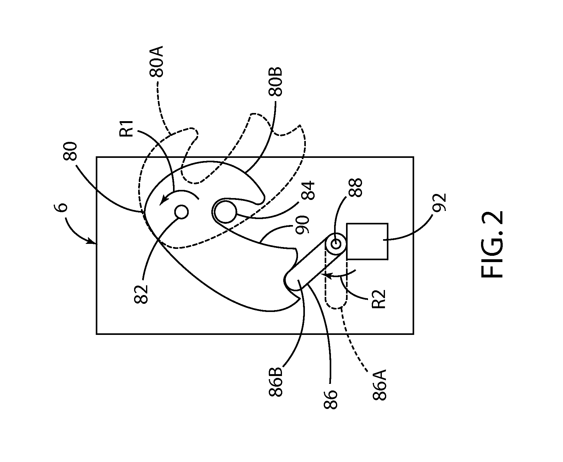
FIG. 2 is a schematic view of a powered latch; and
FIG. 3 is a diagram showing a latch system according to one aspect of the present invention.
DETAILED DESCRIPTION OF THE PREFERRED EMBODIMENTS
For purposes of description herein, the terms "upper," "lower," "right," "left," "rear," "front," "vertical," "horizontal," and derivatives thereof shall relate to the invention as oriented in FIG. 1. However, it is to be understood that the invention may assume various alternative orientations, except where expressly specified to the contrary. It is also to be understood that the specific devices and processes illustrated in the attached drawings, and described in the following specification are simply exemplary embodiments of the inventive concepts defined in the appended claims. Hence, specific dimensions and other physical characteristics relating to the embodiments disclosed herein are not to be considered as limiting, unless the claims expressly state otherwise.
With reference to FIG. 1, a door 1 includes a door structure 2 that may be movably mounted to a vehicle structure 3 in a known manner utilizing hinges 4A and 4B Door 1 may also include an electrically powered latch that is configured to selectively retain the door 1 in a closed position. The powered latch 6 is operably connected to a controller 8. As discussed in more detail below, the controller 8 may comprise an individual control module that is part of the powered latch 6, and the vehicle may include a powered latch 6 at each of the doors of a vehicle. Door 2 may also include an interior unlatch input feature such as an interior unlatch switch 12 that is operably connected to the controller 8, and an exterior unlatch switch 13 that is also operably connected to controller 8. Interior unlatch switch 12 is disposed on an interior side of door 1 where it is accessible from inside the vehicle, and exterior unlatch switch 13 is disposed on an exterior side of door 1 and is accessible from the outside of the vehicle when door 1 is closed.
In use, a user actuates the interior unlatch switch 12 or exterior unlatch switch 13 to generate an unlatch request to the controller 8. As also discussed in more detail below, if the latch 6 is unlatched and/or certain predefined operating perimeters or conditions are present, controller 8 generates a signal causing powered latch 6 to unlatch upon actuation of interior unlatch switch 12. Door 2 may also include an unlock input feature such as an unlock switch 14 that is mounted to an inner side of the door 2. The unlock switch 14 is operably connected to the controller 8. Controller 8 may be configured to store a door or latch lock or unlock state that can be changed by actuation of unlock switch 14. Controller 8 may be configured (e.g. programmed) to deny an unlatch request generated by actuation of the interior unlatch switch 12 or exterior unlatch switch 13 if the controller 8 determines that the powered latch 6 is in a locked state. Controller 8 is preferably a programmable controller that can be configured to unlatch powered latch 6 according to predefined operating logic by programming controller 8. However, controller 8 may comprise electrical circuits and components that are configured to provide the desired operating logic. As used herein, the term "controller" may refer to one or more processors, circuits, electronic devices, and other such components and systems that are arranged to provide the desired control.
With further reference to FIG. 2, powered latch 6 may include a claw 80 that pivots about a pivot 82 and a pawl 86 that is rotatably mounted for rotation about a pivot 88. Pawl 86 can move between a disengaged or unlatched position 86A and a latched or engaged configuration or position 86B. In use, when door 1 is open, claw 80 will typically be in an extended position 80A. As the door 1 is closed, surface 90 of claw 80 comes into contact with a striker 84 that is mounted to the vehicle structure. Contact between striker 84 and surface 90 of claw 80 causes the claw 80 to rotate about pivot 82 in the direction of the arrow "R1" until the claw 80 reaches the closed position 80B. When claw 80 is in the closed position 80B, and pawl 86 is in the engaged position 86B, pawl 86 prevents rotation of claw 80 to the open position 80A, thereby preventing opening of door 1. Claw 80 may be biased by a spring or the like for rotation in a direction opposite the arrow R1 such that the claw 80 rotates to the open position 80A unless pawl 86 is in the engaged position 86B. Pawl 86 may be biased by a spring or the like in the direction of the arrow R2 such that pawl 86 rotates to the engaged position 86B as claw 80 rotates to the closed position 80B as striker 84 engages claw 80 as door 1 is closed. Latch 6 can be unlatched by rotating pawl 86 in a direction opposite the arrow R2 to thereby permit rotation of claw 80 from the closed position 80B to the open position 80A. A powered actuator such as an electric motor 92 may be operably connected to the pawl 86 to thereby rotate the pawl 86 to the disengaged or unlatched position 86A. Controller 30 can unlatch powered latch 6 to an unlatched configuration or state by causing powered actuator 92 to rotate pawl 86 from the latched or engaged position 86B to the unlatched configuration or position 86A. However, it will be understood that various types of powered latches may be utilized in the present invention, and the powered latch 6 need not include the claw 80 and powered pawl 86 as shown in FIG. 2. For example, powered actuator 92 could be operably interconnected with the claw 80 utilizing a mechanical device other than pawl 86 to thereby shift the powered latch 6 between latched and unlatched states. In general, vehicle door 1 can be pulled open if powered latch 6 is in an unlatched state, but the powered latch 6 retains the vehicle door 1 in a closed position when the powered latch 6 is in a latched state or configuration.
With further reference to FIG. 3, a latch system 25 may include a driver's side front powered latch 6A, a passenger side front powered latch 6B, a driver's side rear powered latch 6C and a rear passenger side powered latch 6D. The powered latches 6A-6D are configured to selectively retain the corresponding driver and passenger front and rear doors of a vehicle in a closed position. Each of the powered latches 6A-6D may include a controller 16A-16D, respectively, that is connected to a medium speed data network 18 including network lines 18A-18D. Controllers 16A-16D are preferably programmable controllers, but may comprise electrical circuits that are configured to provide the desired operating logic. The data network 18 may comprise a Medium Speed Controller Area Network ("MS-CAN") that operates according to known industry standards. Data network 18 provides data communication between the controllers 16A-16D and a digital logic controller ("DLC") gateway 20. The DLC gateway 20 is operably connected to a first data network 22, and a second data network 24. First data network 22 may comprise a first High Speed Controller Area Network ("HS1-CAN"), and the second data network 24 may comprise a second High Speed Controller Area Network ("HS2-CAN"). The data networks 22 and 24 may operate according to known industry standards. The first data network 22 is connected to an Instrument Panel Cluster ("IPC") 26, a Restraints Control Module ("RCM") 28, and a Powertrain Control Module ("PCM") 30. The RCM 28 utilizes data from acceleration sensors to determine if a crash event has occurred. The RCM 28 may be configured to deploy passenger restraints and/or turn off a vehicle's fuel supply in the vent a crash is detected. RCM 28 may be configured to generate an Emergency Notification System ("ENS") signal if a crash occurs. The ENS signal may be transmitted over one or both of the data networks 22 and 24 (preferably both). The RCM is also preferably connected ("hard wired`) directly to each powered latch 6A-6D by wires (not shown) such that powered latches 6A-6D receive an ENS signal even if data networks 22 and 24 are not operational. The first high speed data network 22 may also be connected to a display screen 32 that may be positioned in a vehicle interior to provide visual displays to vehicle occupants. The second high speed data network 24 is operably connected to antilock brakes ("ABS") module 34 that includes sensors that measure a speed of the vehicle.
System 25 also includes a Body Control module ("BCM") 40 that is connected to the first high speed data network 22. The body control module 40 is also operably connected to the powered latches 6A-6D by data lines 36A-36D. Controllers 16A-16D may also be directly connected ("hardwired") to control module 40 by electrical conductors such as wires 56A-56D, respectively. Wires 56A-56D may provide a redundant data connection between controllers 16A-16D and controller 40, or the wires 56A-56D may comprise the only data connection between controllers 16A-16D and controller 40. Control module 40 may also be operably interconnected to sensors (not shown) that signal the control module 40 if the vehicle doors are ajar. Control module 40 is also connected to a main vehicle electrical power supply such as a battery 48. Each of the powered latches 6A-6D may be connected to main vehicle power supply 48 by connectors 50A-50D. The powered latches 6A-6D may also include back up power supplies 52 that can be utilized to actuate the powered actuator 92 in the event the power supply from main vehicle power supply ("VPWR") 48 is interrupted or lost. The backup power supplies 52A-52D may comprise capacitors, batteries, or other electrical energy storage devices. In general, the backup power supplies 52A-52D store enough electrical energy to provide for temporary operation of controllers 16A-16d, and to actuate the powered actuators 92 a plurality of times to permit unlatching of the vehicle doors in the event the main power supply/battery 48 fails or is disconnected.
Each of the powered latches 6A-6D is also operably connected to a two pole (for example, both poles normally opened or one pole normally opened and one pole normally closed) interior unlatch switch 12A-12D, respectively, that provide user inputs (unlatch requests). The powered latches 6A-6D are also operably connected to an exterior unlatch switches 54A-54D, respectively. Controllers 16A-16D are also operably connected to unlock switches 14 (FIG. 1). Controllers 16A-16D may be configured to store the Lock Status ("Locked" or "Unlocked") and to utilize the Lock Status for control of powered latches 6A-6D as shown below in Tables 1 and 2.
The controller 40 and individual controllers 16A-16D may be configured to unlatch the powered latches based on various user inputs and vehicle operating perimeters as shown in Table 1:
TABLE-US-00001 TABLE 1 UNLATCH Operation per Door Status of: Normal Non-Crash Behavior (Delay Operation to Validate Input was not from a Crash Event) MS-CAN Interior Rear Door Interior Rear Door 18 Exterior Interior (First Geographic Region) (Second Geographic Region) Latch LOCK Any Front Child Lock Child Lock Child Lock Child Lock Power SPEED STATUS Door Door ON OFF ON OFF OK Speed < Locked & Powered Unlatch Powered Unlatch Powered Unlatch 3 kph Alarm Latch 6 switch 12 Latch 6 switch 12 Latch 6 switch 12 Armed Not actuated Not actuated Not actuated Unlatched 2 times Unlatched 2 times Unlatched 2 times within within within 3 seconds 3 seconds 3 seconds Locked Powered Single Powered Unlock Powered Single Latch 6 actuation of Latch 6 switch 14 Latch 6 actuation of Not Unlatch Not actuated Not Unlatch Unlatched switch 12 Unlatched to unlock, Unlatched switch 12 then Unlatch switch 12 actuated 2 times within 3 seconds Unlocked Single Single Powered Single Powered Single actuation of actuation Latch 6 actuation of Latch 6 actuation of Exterior of Not Unlatch Not Unlatch Unlatch Unlatch Unlatched switch 12 Unlatched switch 12 switch 13 switch 12 3 kph < ANY Powered Unlock Powered Unlock Powered Unlock Speed < Latch 6 switch 14 Latch 6 switch 14 Latch 6 switch 14 8 kph Not actuated Not actuated Not actuated Unlatched to unlock, Unlatched to unlock, Unlatched to unlock, then Unlatch then Unlatch then Unlatch switch switch switch 12 actuated 12 actuated 12 actuated 2 times 2 times 2 times within 3 within 3 within 3 seconds seconds seconds Speed > ANY Powered Unlock Powered Unlock Powered Unlock 8 kph Latch 6 switch 14 Latch 6 switch 14 Latch 6 switch 14 Not actuated Not actuated Not actuated Unlatched to unlock, Unlatched to unlock, Unlatched to unlock, then Unlatch then Unlatch then Unlatch switch switch switch 12 actuated 12 actuated 12 actuated 2 times 2 times 2 times within 3 within 3 within 3 seconds seconds seconds Down/ Unknown Unknown Last Unlock Unlock Unlock Unlock Unlock Lost Known switch 14 switch 14 switch 14 switch 14 switch 14 State actuated actuated actuated actuated actuated to unlock, to unlock, to unlock, to unlock, to unlock, then Unlatch then Unlatch then Unlatch then Unlatch then Unlatch switch switch switch switch switch 12 actuated 12 actuated 12 actuated 12 actuated 12 actuated 2 times 2 times 2 times 2 times 2 times within 3 within 3 within 3 within 3 within 3 seconds seconds seconds seconds seconds
TABLE-US-00002 TABLE 2 UNLATCH Operation per Door Crash Behavior (Operation After Crash Event Recognized) Status of: Interior Door MS-CAN 18 LOCK Exterior Any Interior Front (First and Second Geographic Region) Latch Power SPEED STATUS Door Door Child Lock ON Child Lock OFF OK Speed < Locked & State Not Allowed (RCM 28 Off when Security System Armed) 3 kph Alarm Armed Locked Powered Latch Unlock switch 14 Powered Latch 6 Unlock switch 14 6 Not Unlatched actuated to unlock, Not Unlatched actuated to unlock, then Unlatch switch then Unlatch switch 12 actuated 2 times 12 actuated 2 times within 3 seconds within 3 seconds Unlocked Single actuation of Unlock switch 14 Powered Latch 6 Unlock switch 14 Exterior Unlatch actuated to unlock, Not Unlatched actuated to unlock, switch 13 after then Unlatch switch then Unlatch switch 10 seconds 12 actuated 2 times 12 actuated 2 times within 3 seconds within 3 seconds 3 kph < ANY Powered Latch Unlock switch 14 Powered Latch 6 Unlock switch 14 Speed < 6 Not Unlatched actuated to unlock, Not Unlatched actuated to unlock, 8 kph then Unlatch then Unlatch switch 12 actuated switch 12 actuated 2 times within 3 2 times within 3 seconds seconds Speed > ANY Powered Latch 6 Unlock switch 14 Powered Latch 6 Unlock switch 14 8 kph Not Unlatched actuated to unlock, Not Unlatched actuated to unlock, then Unlatch then Unlatch switch 12 actuated switch 12 actuated 2 times within 3 2 times within 3 seconds seconds Down/Lost Unknown Unknown Powered Latch 6 Unlock switch 14 Powered Latch 6 Unlock switch 14 Not Unlatched actuated to unlock, Not Unlatched actuated to unlock, then Unlatch then Unlatch switch 12 actuated switch 12 actuated 2 times within 3 2 times within 3 seconds seconds
In Tables 1 and 2, the term "Latch Power" signifies that the powered latches 6A-6D are receiving electrical power from the main vehicle power supply 48. Thus, if the vehicle main power supply 48 is not functioning properly and/or if the powered latches 6A-6D are electrically disconnected from main vehicle power supply 48, "Latch Power" will be "down" or "not ok."
It will be understood that the predefined speeds listed for implementation of the control logic in Tables 1 and 2 may vary depending on the requirements of a particular application. For example, the speed of 8 kph may be larger (e.g. 20 kph) or smaller, and the 3 kph speed may be lower (e.g. 1 or 2 kph).
As shown in Tables 1 and 2, the controllers 16A-16C and/or control module 40 may be configured (e.g. programmed) to control unlatching of powered latches 6A-6D according to different criteria as required for different geographic areas. Additionally, the control module may be configured to control unlatching behavior differently when a crash event condition is present as compared to normal or non-crash conditions. Table 1 represents an example of unlatching behavior (control logic) during normal (non-crash) conditions whereas Table 2 represents unlatching behavior (control logic) during crash conditions. The controllers 16A-16C and/or control module 40 may be configured to recognize a crash condition by monitoring the data network for a crash signal from the RCM 28 and/or by monitoring various other direct signal inputs from the RCM 28. As discussed below, the RCM 28 may be configured to determine if a crash event has occurred (i.e. a crash condition exists) and generate one or more crash signals that may be communicated to the latch controllers 16A-16C and/or control module 40. Upon recognizing that a crash condition exists, the controller 16A-16C and/or control module 40 may also be configured to initiate a timer and to disallow any unlatching operation for a predefined time interval (e.g. 3 seconds) before resuming the crash behavior (control logic or operating mode) described in Table 2.
The controllers 16A-16D and/or control module 40 may be configured to provide a first operating mode wherein the powered latches 6A-6D are unlatched if interior unlatch switch 12 is actuated once. The system may also include a second operating mode. When the system is in the second operating mode, the interior unlatch switch 12 must be actuated at least two times within a predefined time period (e.g. 3 seconds). For example, this operating mode may be utilized when the vehicle is locked and the vehicle security system is armed.
As discussed above, the control module 40 may be operably interconnected with the controllers 16A-16D by data network 18 and/or data lines 36A-36D. Control module 40 may also be operably interconnected with the controllers 16A-16D by "hard" lines or conductors 56A-56D to provide redundancy. Alternatively, the system 25 may be configured such that the control module 40 is connected to the controllers 16A-16D only by network 18, or only by data lines 36A-36D, or only by conductors 56A-56D. Also, the RCM 28 may be connected to controllers 16A-16D of powered latches 6A-6D by data network 18, DLC gateway 20, and HS1-CAN 22, and RCM 28 may also be "hardwired" directly to the controllers 16A-16D of powered latches 6A-6D by electrical lines (not shown). These redundant connections between latch controllers 16A-16D and RCM 28 ensure that the powered latches 6A-6D can receive an Emergency Notification System ("ENS") signal directly from RCM 28 in the event one or more of the data networks 18 and 20 and/or other components malfunction.
During normal operation, or when the vehicle is experiencing various operating failures, the system 25 may also be configured to control the powered latches 6A-6D based on various operating parameters and/or failures within the vehicles electrical system, the data communication network, the hardwires, and other such parameters or events.
For example, during normal operation the system 25 may be configured to unlatch powered latches 6A-6D if interior unlatch switch 12 is actuated at least once and if the vehicle is traveling below 3 kph or other predefined speed. The speed may be determined utilizing suitable sensors (e.g. sensors in ABS module 34). If the vehicle is traveling at or below 3 kph, the powered latches 6A-6D may also be unlatched if exterior unlatch switch 54 is actuated one or more times while unlocked. However, the controllers 16A-16D may be configured such that if the vehicle is traveling above 3 kph, the latches 6A-6D cannot be unlatched by actuating exterior unlatch switches 54A-54D. Likewise, if the vehicle is traveling below 3 kph and while locked and armed, the system 25 may be configured to unlatch powered latches 6A-6D if interior unlatch switches 12A-12D are actuated at least two times within a predefined time interval (e.g. 3 seconds).
The system 25 may be configured to debounce interior unlatch switches 12A-12D and/or exterior unlatch switches 54A-54D at a first time interval (e.g. 35 ms) during normal vehicle operation. However, the debounce may be performed at longer time intervals (100-150 ms) if the vehicle is in gear (e.g. PCM 30 provides a signal indicating that the vehicle transmission gear selector is in a position other than "Park" or "Neutral").
Furthermore, the system 25, in crash operation for example, may be configured to unlatch the powered latches 6A-6D based on multiple inputs from interior unlatch switch 12 and/or interior unlock switch 14. Specifically, the controllers 16A-16D may be configured to provide a three-input mode or feature and unlatch powered latches 6A-6D if three separate inputs from interior unlatch switches 12A-12D and interior unlock switches 14A-14D are received within a predefined time interval (e.g. 3 seconds or 5 seconds) in any sequence. For example, controllers 16A-16D may be configured such that three actuations of interior unlatch switch 12 or three actuations of unlock switch 14 within the predefined time interval results in unlatching of powered latches 6A-6D. Also, actuation of unlock switch 14 followed by two actuations of unlatch switch 12 within the predefined time period could be utilized as a combination of inputs that would unlatch powered latches 6A-6D. Similarly, two actuations of the unlatch switch 12 followed by a single actuation of unlock switch 14 within the predefined time period may be utilized as an input that causes the powered latches 6A-6D to unlatch. Still further, two actuations of unlock switch 14 followed by a single actuation of interior unlatch switch 12 could also be utilized as a combination of inputs resulting in unlatching of powered latches 6A-6D. Thus, three inputs from unlatch switch 12 and/or unlock switch 14 in any combination or sequence within a predefined time interval may be utilized by the system 25 to unlatch powered latches 6A-6D. This control scheme prevents inadvertent unlatching of powered latches 6A-6D, but also permits a user who is under duress to unlatch the doors if three separate inputs in any sequence or combination are provided. Additionally, system 25 may be configured such that the three-input mode/feature is active only under the presence of certain conditions. For example, the system 25 (e.g. controllers 16A-16D) may be configured to provide a three-input mode-feature if a crash condition is present and/or loss of data network condition occurs as recognized by the controllers 16A-16D.
If the system 25 includes only data network connections 36A-36D, or only includes "hardwire" lines 56A-56D, the controllers 16A-16D may be configured to require a plurality of actuations of interior unlatch switch 12 if either the network or hardwire connectivity with RCM 28 is lost. If the controllers 16A-16D cannot communicate with the RCM 28, the controllers 16A-16D do not "know" the status of RCM 28, such that the controllers 16A-16D cannot "know" if a crash or fuel cut-off event has occurred. Accordingly, the controllers 16A-16D can be configured to default to require multiple actuations of interior unlatch switches 12A-12D in the event communication with RCM 28 (or other components) is lost to insure that the powered latches 6A-6D are not inadvertently unlatched during a crash event that was not detected by the system due to a loss of communication with the RCM 28. Similarly, if the network connectivity is lost, the controllers 16A-16D will be unable to "know" the vehicle speed and may default to utilizing the last known valid vehicle speed. Alternatively, the controllers 16A-16D may be configured instead to assume by default that the vehicle speed is less than 3 kph if network connectivity is lost. This may be utilized in the unlatch operation behavior from processing the exterior unlatch switches 54A-54D and/or the interior switches. It will be understood that controllers 16A-16D may be configured to determine if network connectivity has been "lost" for purposes of controlling latch operations based on predefined criteria (e.g. an intermittent data connection) that does not necessarily require a complete loss of network connectivity.
The system 25 may include both network (data) connections 18-18D and "hard" lines (not shown), wherein the hard lines directly interconnect the controllers 16A-16D to RCM 28 whereby the controllers 16A-16D receive an ENS signal and through the data and/or hardwire connections, the controllers 16A-16D may be configured to default to a mode requiring multiple actuations of interior unlatch switch 12 if both the data and hardwire connections are disrupted or lost. However, if either of the data or hardwire connections remain intact, the controllers 16A-16D can be configured to require only a single actuation of interior unlatch switch 12, provided the vehicle is known to be below a predefined maximum allowable vehicle speed and other operating parameters that would otherwise trigger a requirement for multiple actuations of interior unlatch switches 12A-12D.
Furthermore, the controllers 16A-16D may be configured to default to a mode requiring multiple actuations of interior unlatch switches 12A-12D if the power to latches 6A-6D from main vehicle power supply 48 is interrupted, even if the network connectivity with RCM 28 remains intact. This may be done to preserve the backup power supplies 52A-52D. Specifically, continued monitoring of the data network by controllers 16A-16D will tend to drain the backup power supplies 52A-52D, and the controllers 16A-16D may therefore be configured to cease monitoring data from data lines 36A-36D and/or network 18 in the event power from main vehicle power supply 48 is lost. Because the controllers 16A-16D cease monitoring the data communication upon failure of main power supply 48, the individual controllers 16A-16D cannot determine if a crash event has occurred (i.e. the controllers 16A-16D will not receive a data signal from RCM 28), and the controllers 16A-16D therefore default to require multiple actuations of interior unlatch switches 12A-12D to insure that the latches 6A-6D are not inadvertently unlatched during a crash event that was not detected by controllers 16A-16D. Additionally, in such cases the controllers 16A-16D will likewise be unable to determine vehicle speed and may be configured (e.g. programmed) to default to utilizing the last known valid vehicle speed. Alternatively, the controllers 16A-16D may instead be configured to "assume" by default that the vehicle speed is less than a predefined speed (e.g. 3 kph). These defaults, assumptions may be utilized in the unlatch operation behavior when processing inputs from the exterior unlatch switches 54A-54D and/or the interior switches 12A-12D.
Furthermore, the system may be configured to default to require multiple actuations of interior unlatch switches 12A-12D in the event the data network connection (network 18 and/or data lines 36A-36D) connectivity between the controllers 16A-16D and RCM 28 is lost. Specifically, even if the "hard" lines 56A-56D remain intact, the data transfer rate of the hard lines 56A-56D is significantly less than the data transfer rate of the network 18 and data lines 36A-36D, such that the controllers 16A-16D may not receive crash event data from RCM 28 quickly enough to shift to a mode requiring multiple actuations of interior unlatch switches 12A-12D if the crash data can only be transmitted over the hard lines 38A-38D. Thus, defaulting to a mode requiring multiple actuations of interior unlatch switches 12A-12D upon failure of data communications (network 18 and/or data lines 36A-36D) even if the hardwire communication lines remain intact insures that the powered latches 6A-6D are not inadvertently unlatched during a crash event that was detected by the controllers 16A-16D only after a delay due to a slower data transfer rate. Similarly, in such cases where the controllers 16A-16D are not communicating over the data network, they will be unable to "know" the vehicle speed as well and may default to utilizing the last known valid vehicle speed. Alternatively, the controllers 16A-16D may instead be configured to "assume" by default that the vehicle speed is less than a predefined speed (e.g. 3 kph). These defaults/assumptions may be utilized in the unlatch operation behavior when processing inputs from the exterior unlatch switches 54A-54D and/or the interior switches 12A-12D.
The controller 40 and individual controllers 16A-16D may, alternatively, be configured to unlatch the powered latches based on various user inputs and vehicle operating parameters as shown in Table 3.
TABLE-US-00003 TABLE 3 UNLATCH Operation per Door Normal during Non-Crash Behavior Status of: (Delay Operation 120 ms to Validate Input was not from a Crash Event) MS-CAN 18 Exterior Interior Interior Rear Door Interior Rear Door ENS LOCK Any Front (First Geographic Region) (Second Geographic Region) Latch Power SPEED STATUS Door Door Child Lock ON Child Lock OFF Child Lock ON Child Lock OFF All 3 OK Speed < Locked & Powered Unlatch switch 12 Powered Latch Unlatch switch 12 Powered Latch Unlatch switch 12 3 kph Alarm Latch actuated 2 times 6 Not Unlatched actuated 2 times 6 Not Unlatched actuated 2 times Armed 6 Not within 3 seconds within 3 seconds within 3 seconds Unlatched Or Unlock Or Unlock Or Unlock switch 14 actuated switch 14 actuated switch 14 actuated followed by Unlatch followed by Unlatch followed by Unlatch switch 12 actuated switch 12 actuated switch 12 actuated within 3 seconds within 3 seconds within 3 seconds Locked Powered Single actuation of Powered Latch 6 Unlock switch 14 Powered Latch 6 Single actuation of Latch Unlock switch 12 Or Not Unlatched actuated to unlock, Not Unlatched Unlock switch 12 or 6 Not (Config1 = Enabled then Unlatch switch (Config1 = Enabled Unlatched Unlock switch 14 12 actuated (no Unlock switch 14 actuated followed by time bound) actuated followed by Unlatch switch 12 Unlatch switch 12 actuated actuated within 3 seconds) within 3 seconds) Unlocked Single Single actuation of Powered Latch 6 Single actuation of Powered Latch 6 Single actuation of actuation Unlock switch 12 Or Not Unlatched Unlock switch 12 Or Not Unlatched Unlock switch 12 or of (Config1 = Enabled (Config1 = Enabled (Config1 = Enabled Exterior Unlock switch 14 Unlock switch 14 Unlock switch 14 Unlatch actuated followed by actuated followed by actuated followed by switch 13 Unlatch switch 12 Unlatch switch 12 Unlatch switch 12 actuated actuated actuated within 3 seconds) within 3 seconds) within 3 seconds) 3 kph < Unlocked Single Unlock switch 14 Powered Latch 6 Unlock switch 14 Powered Latch 6 Unlock switch 14 Speed < actuation actuated followed by Not Unlatched actuated followed by Not Unlatched actuated followed by 20 kph of Unlatch switch 12 Unlatch switch 12 Unlatch switch 12 Exterior actuated within 3 actuated within 3 actuated within 3 Unlatch seconds seconds seconds switch 13 3 kph < Locked Powered Unlock switch 14 Powered Latch 6 Unlock switch 14 Powered Latch 6 Unlock switch 14 Speed < Latch 6 actuated followed by Not Unlatched actuated followed by Not Unlatched actuated followed by 20 kph Not Unlatch switch 12 Unlatch switch 12 Unlatch switch 12 Unlatched actuated within 3 actuated within 3 actuated within 3 seconds seconds seconds Speed > ANY Powered Unlock switch 14 Powered Latch 6 Unlock switch 14 Powered Latch 6 Unlock switch 14 20 kph Latch 6 actuated followed by Not Unlatched actuated followed by Not Unlatched actuated followed by Not Unlatch switch 12 Unlatch switch 12 Unlatch switch 12 Unlatched actuated within 3 actuated within 3 actuated within 3 seconds seconds seconds
The operating logic shown above in Table 3 corresponds to normal non-crash operating conditions. In Table 3, "LATCH Power" signifies that a given powered latch 6A-6D is receiving electrical power from the main vehicle electrical power system 48. Thus, Table 3 applies if MS-CAN 18 is "up" (i.e. operating properly) and no ENS (crash) signal has been generated by the RCM 28, and the powered latches 6A-6D have electrical power from the vehicle's main power system 48. If these conditions are present and interior unlatch switch 12 or exterior unlatch switch 13 is actuated, the system initially delays implementation of the unlatch operations listed in Table 3 by 120 ms to validate that the input from switch 12 and/or switch 13 was not caused by a crash event. As discussed below, if a crash even has occurred, the system implements the control parameters/logic of Tables 5 and 6.
As shown in Table 3, the control system may be configured to provide a first operating logic for a first geographic region, and a second operating logic for a second geographic region with respect to the child lock state. Specifically, as shown in Table 3, when the child lock is in an ON state, the powered latch is not unlatched due to actuation of interior unlatch switch 12 under any circumstances (when the child lock is ON, actuation of exterior unlatch switch 13 will unlatch the door if it is not locked). However, if the child lock is in an "OFF" state, the system operates according to different logic depending on whether or not the control system is configured for a first geographic region or a second geographic region. The system can be configured for the first geographic region or the second geographic region by controlling one or more of the controllers 16A-16C and/or control module 40, and/or by modifying the circuit of FIG. 4. The ability to reconfigure the control system to provide different operating logic depending on the requirements of a particular market greatly reduces the need to design/fabricate different latch systems for different geographic regions.
The controllers may also be configured to control the powered latches based on the status of the MS-CAN 18, ENS, and Latch Power as shown in Table 4:
TABLE-US-00004 TABLE 4 UNLATCH Operation per Door Normal Non-Crash Behavior (Delay Operation 120 ms to Validate Input was not from a Crash Event) Interior Rear Door Interior Rear Door MS-CAN 18 Exterior Interior (First Geographic Region) (Second Geographic Region) ENS LOCK Any Front Child Lock Child Lock Child Lock Child Lock Latch Power SPEED STATUS Door Door ON OFF ON OFF Last Known Lost Unknown Unlocked Exterior Unlock Powered Unlock Powered Unlock MS-CAN MS- Unlatch switch 14 Latch 6 switch 14 Latch switch 14 18 = Down CAN Switch 13 actuated Not actuated 6 Not actuated Last Known 18 actuated followed Unlatched followed Unlatched followed ENS = UP 2 times by by by Latch within Unlatch Unlatch Unlatch Power = 3 seconds switch switch switch Down Locked Powered 12 actuated 12 actuated 12 actuated Latch 6 within within within Not 3 seconds 3 seconds 3 seconds Unlatched Last Known Lost Unknown Unlocked Exterior Unlock Powered Unlock Powered Unlock MS-CAN MS- Unlatch switch 14 Latch 6 switch 14 Latch 6 switch 14 18 = Down CAN Switch 13 actuated Not actuated Not actuated Last Known 18 actuated followed Unlatched followed Unlatched followed ENS = UP 2 times by by by Latch Power = within Unlatch Unlatch Unlatch UP 3 seconds switch switch switch 12 actuated 12 actuated 12 actuated within within within 3 seconds 3 seconds 3 seconds Last Known Lost Last Any Normal- Normal- Powered Normal- Powered Normal- MS-CAN ENS known Uses Last Uses Last Latch 6 Uses Last Latch 6 Uses Last 18 = Down & lost speed Known Known Not Known Not Known Last Known MS- valid State State Unlatched State Unlatched State ENS = Down CAN of Vehicle of Vehicle of Vehicle of Vehicle Latch Power = 18 speed, lock speed, lock speed, lock speed, lock UP state, state, state, state, Last known PRNDL, PRNDL, PRNDL, PRNDL, state = Normal and Ignition and Ignition and Ignition and Ignition MS-CAN until new until new until new until new 18 sleep information information information information Last Known Lost Last Unlocked Exterior Unlock Powered Unlock Powered Unlock MS-CAN ENS known Unlatch switch 14 Latch 6 switch 14 Latch 6 switch 14 18 = Down & lost speed Switch 13 actuated Not actuated Not actuated Last Known MS- valid actuated followed Unlatched followed Unlatched followed ENS = Down CAN 2 times by by by Latch Power = 18 within Unlatch Unlatch Unlatch UP 3 seconds switch switch switch Last Known Locked Powered 12 actuated 12 actuated 12 actuated State = NOT Latch 6 within within within Normal Not 3 seconds 3 seconds 3 seconds MS-CAN Unlatched 18 sleep Last Known Lost Last Unlocked Exterior Unlock Powered Unlock Powered Unlock MS-CAN ENS known Unlatch switch 14 Latch 6 switch 14 Latch 6 switch 14 18 = Down & lost speed Switch 13 actuated Not actuated Not actuated Last Known MS- valid actuated followed Unlatched followed Unlatched followed ENS = Down CAN 2 times by by by Latch 18 within Unlatch Unlatch Unlatch Power = Down 3 seconds switch switch switch Locked Powered 12 actuated 12 actuated 12 actuated Latch 6 within within within Not 3 seconds 3 seconds 3 seconds Unlatched MS-CAN Lost Known Unlocked Exterior Unlock Powered Unlock Powered Unlock 18 = UP ENS but may Unlatch switch 14 Latch 6 switch 14 Latch switch 14 ENS = Down be in Switch 13 actuated Not actuated 6 Not actuated Latch Power = UP crash actuated followed Unlatched followed Unlatched followed Last Known state = 2 times by by by NOT Normal within Unlatch Unlatch Unlatch MS-CAN 18 sleep 3 seconds switch switch switch (if Latch Power Locked Powered 12 actuated 12 actuated 12 actuated down then Latch 6 within within within MS-CAN Not 3 seconds 3 seconds 3 seconds Down) Unlatched MS-CAN Lost Known ANY NORMAL NORMAL Powered NORMAL Powered NORMAL 18 = UP ENS but may Latch Latch ENS = Down be in 6 Not 6 Not Last Known State = crash Unlatched Unlatched Normal Sleep (if Latch Power down then MS-CAN Down)
The operating logic shown in Table 4 may be utilized if the vehicle speed is unknown due to the MS-CAN 18 network communication being lost and/or if the ENS is lost.
Furthermore, as shown in Tables 5 and 6, the system may be configured to operate the powered latches if a crash event is recognized.
TABLE-US-00005 TABLE 5 UNLATCH Operation per Door Status of: Crash Behavior (Operation After Crash Event Recognized) MS-CAN 18 Interior Door Or LOCK Exterior Any Interior Front (First and Second Geographic Region) Latch Power SPEED STATUS Door Door Child Lock ON Child Lock OFF OK Speed < Locked & State Not Allowed (RCM 28 Off when Security System Armed) 3 kph Alarm Armed Locked Powered Latch Powered Latch Powered Latch 6 Powered Latch 6 Not Unlatched 6 Not Unlatch Not Unlatched 6 Not Unlatch for first 6 seconds for first 6 seconds. for first 6 seconds. After 6 seconds After 6 seconds After 6 seconds unlatch according Unlock switch 14 Unlock switch 14 to noncrash (Table actuated to unlock, actuated to unlock, 4) but treat as then Unlatch switch then Unlatch switch vehicle speed = 0 12 actuated within 3 12 actuated within 3 seconds or Unlatch seconds or Unlatch switch 12 actuated switch 12 actuated 2 times within 3 2 times within 3 seconds. seconds. Unlocked Powered Latch Powered Latch Powered Latch 6 Powered Latch 6 Not Unlatched 6 Not Unlatch Not Unlatched 6 Not Unlatch for first 6 seconds. for first 6 seconds. for first 6 seconds. After 6 seconds After 6 seconds After 6 seconds unlatch according Unlock switch 14 Unlock switch 14 to noncrash (Table actuated to unlock, actuated to unlock, 4) but treat as then Unlatch switch then Unlatch switch vehicle speed = 0. 12 actuated within 3 12 actuated within 3 seconds or Unlatch seconds or Unlatch switch 12 actuated switch 12 actuated 2 times within 3 2 times within 3 seconds. seconds. 3 kph < ANY Powered Latch Powered Latch Powered Latch 6 Powered Latch Speed < 6 Not Unlatched 6 Not Unlatch Not Unlatched 6 Not Unlatch 20 kph for first 6 seconds. for first 6 seconds. for first 6 seconds. After 6 seconds After 6 seconds After 6 seconds unlatch according Unlock switch 14 Unlock switch 14 to noncrash (Table actuated to unlock, actuated to unlock, 4) but treat as then Unlatch switch then Unlatch switch vehicle speed = 0. 12 actuated within 3 12 actuated within 3 seconds or Unlatch seconds or Unlatch switch 12 actuated switch 12 actuated 2 times within 3 2 times within 3 seconds. seconds. Speed > ANY Powered Latch Powered Latch Powered Latch 6 Powered Latch 20 kph 6 Not Unlatched 6 Not Unlatch Not Unlatched 6 Not Unlatch for first 6 seconds. for first 6 seconds. for first 6 seconds. After 6 seconds After 6 seconds After 6 seconds unlatch according Unlock switch 14 Unlock switch 14 to noncrash (Table actuated to unlock, actuated to unlock, 4) but treat as then Unlatch switch then Unlatch switch vehicle speed = 0. 12 actuated within 3 12 actuated within 3 seconds or Unlatch seconds or Unlatch switch 12 actuated switch 12 actuated 2 times within 3 2 times within 3 seconds. seconds.
TABLE-US-00006 TABLE 6 UNLATCH Operation per Door Crash Behavior Status of: (Operation After Crash Event Recognized) MS-CAN 18 Interior Door ENS LOCK Exterior Any Interior Front (First and Second Geographic Region) Latch Power SPEED STATUS Door Door Child Lock ON Child Lock OFF Last Known Lost MS- Unknown ANY Powered Latch Powered Latch 6 Not Powered Latch Powered Latch 6 Not MS-CAN 18 = Down CAN 18 6 Not Unlatched Unlatch for first 6 6 Not Unlatched Unlatch for first 6 Last Known for first 6 seconds. seconds. After 6 seconds. After 6 ENS = UP After 6 seconds unlatch seconds Unlock switch seconds Unlock switch Latch Power = according to noncrash 14 actuated to unlock, 14 actuated to unlock, down but treat as vehicle then Unlatch switch 12 then Unlatch switch 12 speed = 0. actuated within 3 actuated within 3 seconds or Unlatch seconds or Unlatch switch 12 actuated 2 switch 12 actuated 2 times within 3 times within 3 seconds seconds Last Known Lost MS- Unknown ANY Powered Latch Powered Latch 6 Not Powered Latch Powered Latch 6 Not MS-CAN 18 = Down CAN 18 6 Not Unlatched Unlatch for first 6 6 Not Unlatched Unlatch for first 6 Last Known for first 6 seconds. seconds. After 6 seconds. After 6 ENS = UP After 6 seconds unlatch seconds Unlock switch seconds Unlock switch Latch Power = according to noncrash 14 actuated to unlock, 14 actuated to unlock, UP but treat as vehicle then Unlatch switch 12 then Unlatch switch 12 speed = 0. actuated within 3 actuated within 3 seconds or Unlatch seconds or Unlatch switch 12 actuated 2 switch 12 actuated 2 times within 3 times within 3 seconds seconds Last Known Lost ENS Last ANY Powered Latch Powered Latch 6 Not Powered Latch Powered Latch 6 Not MS-CAN 18 = Down & Lost known 6 Not Unlatched Unlatch for first 6 6 Not Unlatched Unlatch for first 6 Last Known MS-CAN speed for first 6 seconds. seconds. After 6 seconds. After 6 ENS = Down 18 valid After 6 seconds unlatch seconds Unlock switch seconds Unlock switch Latch Power = according to noncrash 14 actuated to unlock, 14 actuated to unlock, UP but treat as vehicle then Unlatch switch 12 then Unlatch switch 12 Last known state = speed = 0. actuated within 3 actuated within 3 Normal CAN seconds or Unlatch seconds or Unlatch sleep switch 12 actuated 2 switch 12 actuated 2 times within 3 times within 3 seconds seconds Last Known Lost ENS Last ANY Powered Latch Powered Latch 6 Not Powered Latch Powered Latch 6 Not MS-CAN 18 = Down & lost known 6 Not Unlatched Unlatch for first 6 6 Not Unlatched Unlatch for first 6 Last Known MS-CAN speed for first 6 seconds. seconds. After 6 seconds. After 6 ENS = Down 18 valid After 6 seconds unlatch seconds Unlock switch seconds Unlock switch Latch Power = according to noncrash 14 actuated to unlock, 14 actuated to unlock, UP but treat as vehicle then Unlatch switch 12 then Unlatch switch 12 Last Known State = speed = 0. actuated within 3 actuated within 3 Not Normal CAN seconds or Unlatch seconds or Unlatch sleep switch 12 actuated 2 switch 12 actuated 2 times within 3 times within 3 seconds seconds Last Known Lost ENS Last ANY Powered Latch Powered Latch 6 Not Powered Latch Powered Latch 6 Not MS-CAN 18 = Down & lost known 6 Not Unlatched Unlatch for first 6 6 Not Unlatched Unlatch for first 6 Last Known MS-CAN speed for first 6 seconds. seconds. After 6 seconds. After 6 ENS = Down 18 valid After 6 seconds unlatch seconds Unlock switch seconds Unlock switch Latch Power = according to noncrash 14 actuated to unlock, 14 actuated to unlock, Down but treat as vehicle then Unlatch switch 12 then Unlatch switch 12 speed = 0. actuated within 3 actuated within 3 seconds or Unlatch seconds or Unlatch switch 12 actuated 2 switch 12 actuated 2 times within 3 times within 3 seconds seconds MS-CAN 18 = UP Lost ENS Known ANY Powered Latch Powered Latch 6 Not Powered Latch Powered Latch 6 Not ENS = Down but may be 6 Not Unlatched Unlatch for first 6 6 Not Unlatched Unlatch for first 6 Latch Power = in crash for first 6 seconds. seconds. After 6 seconds. After 6 UP After 6 seconds unlatch seconds Unlock switch seconds Unlock switch Last known state = according to noncrash 14 actuated to unlock, 14 actuated to unlock, Not Normal CAN but treat as vehicle then Unlatch switch 12 then Unlatch switch 12 sleep (if Latch Power speed = 0. actuated within 3 actuated within 3 down then CAN seconds or Unlatch seconds or Unlatch Down) switch 12 actuated 2 switch 12 actuated 2 times within 3 times within 3 seconds seconds MS-CAN 18 = UP Lost ENS Known ANY Powered Latch Powered Latch 6 Not Powered Latch Powered Latch 6 Not ENS = Down but may be 6 Not Unlatched Unlatch for first 6 6 Not Unlatched Unlatch for first 6 Last known State = in crash for first 6 seconds. seconds. After 6 seconds. After 6 Normal Sleep After 6 seconds unlatch seconds Unlock switch seconds Unlock switch (if Latch Power according to noncrash 14 actuated to unlock, 14 actuated to unlock, down then MS-CAN but treat as vehicle then Unlatch switch 12 then Unlatch switch 12 down) speed = 0. actuated within 3 actuated within 3 seconds or Unlatch seconds or Unlatch switch 12 actuated 2 switch 12 actuated 2 times within 3 times within 3 seconds seconds
Still further, as shown in Table 6, the system may be configured to control the powered latches based on the status of the MS-CAN network 18, ENS, Latch Power, and vehicle speed after a crash event is recognized.
In Tables 3-6, "ENS" represents the presence of a signal from the Emergency Notification System. The ENS comprises a signal from the restraints control module 28. The restraints control module 28 may be configured to continuously (or at very short time intervals) send a signal over the HS1-CAN 22. The signal is sent continuously unless the RCM 28 and/or HS1-CAN 22 or other components are damaged (e.g. in a crash). The RCM 28 normally sends a continuous "no event" signal. However, in the event of a crash, the RCM 28 may send a "deployment event" signal or a "fuel shutoff event" signal. The latch system 25 may be configured to treat the "deployment event" and "fuel shut off event" signals from RCM 28 in the same manner, and interpret these signals as meaning that a crash event has occurred. In the event the ENS signal is lost completely, the system controls the powered latches as shown in Tables 4 and 6.
Also, in Tables 3, 4, and 6, the latch power may be utilized as an input by the system 25 to control the unlatching of the powered latches. The latch power of the tables corresponds to the status of the backup power supplies 52 of the powered latches 6A-6D. Specifically, the body control module 40 and/or individual controllers 16A-16D may be configured to continuously check the individual backup power supplies 52A-52D to thereby control operation based on whether or not the individual latch power supplies 52 are "up" (working properly according to predefined criteria) or "down" (not operating properly according to predefined criteria).
As also shown in Tables 4 and 6, the system 25 may be configured to take into account the condition of the MS-CAN "sleep." Specifically, the MS-CAN 18, HS1-CAN 22, and/or HS2-CAN 24 may be configured to go into a "sleep" mode to reduce power consumption if the components of the system are sufficiently inactive according to predefined criteria. When the data networks 18, 22, and/or 24 go into the "sleep" mode, the system generates a signal whereby the various components in the system can determine if the networks 18, 22, and 24 are in sleep mode or if the networks have stopped functioning due to a loss of power or other malfunction. Thus, for example, as shown in Table 4, if the powered latch system 25 determines that the last known state was not a normal MS-CAN 18 sleep state, this indicates that the MS-CAN 18 is not in operation rather than being in a sleep mode. If the last known state was normal MS-CAN 18 sleep mode, the system controls the powered latches 6A-6D accordingly. As shown in Table 4, when the child lock is OFF, the system utilizes a normal operating logic if the last known state is normal MS-CAN 18 sleep. However, in the event the last known state is not normal MS-CAN 18 sleep, the interior rear door is only unlatched if the unlock switch 14 is actuated followed by unlatch switch 12 being actuated within 3 seconds. As shown in Table 4, this aspect of the control logic is the same in the first and second geographic regions.
Also, as noted above and as shown in Tables 3 and 4, the unlatching operations are initially delayed by 120 ms following actuation of unlatch switch 12 or 13. The 120 ms delay is utilized by the system to determine if the actuation of switch 12 or 13 was due to a crash event. Specifically, if one or both of the unlatch switches 12 or 13 are actuated due to a crash event, the RCM 28 will generate a signal in less than 120 ms indicating that a crash event (e.g. deployment event or fuel shutoff event) has occurred. If a crash event has occurred, the operation of the powered latches is controlled as shown in Tables 5 and 6 rather than the control logic shown in Tables 3 and 4.
As shown in Tables 5 and 6, actuation of exterior switch 13 does not, under any circumstances, result in unlatching during the first 6 seconds following a crash event (i.e. a "crash" signal from RCM 28). Thus, exterior unlatching following a crash event is delayed or blocked for a predefined period of time. The delay is preferably about 6 seconds, but it could be as short as 1 second, or it could be 30 seconds, 60 seconds, or other suitable period of time.
It is to be understood that variations and modifications can be made on the aforementioned structure without departing from the concepts of the present invention, and further it is to be understood that such concepts are intended to be covered by the following claims unless these claims by their language expressly state otherwise.
* * * * *
References
-
nhtsa.gov/cars/rules/rulings/DoorLocks/DoorLocks_NPRM.html#VI_C
-
oldcarsweekly.com/car-of-the-week/car-of-the-week-1947-lincoln-convertible
-
youtube.com/watch?v=DLDqmGQU6L0
-
autoblog.com/2011/05/14/friends-videotape-man-trapped-inside-c6-corvette-with-dead-bat
-
corvetteonline.com/news/zr1-owner-calls-911-after-locking-self-in-car
-
D00000
D00001
D00002
D00003
XML
uspto.report is an independent third-party trademark research tool that is not affiliated, endorsed, or sponsored by the United States Patent and Trademark Office (USPTO) or any other governmental organization. The information provided by uspto.report is based on publicly available data at the time of writing and is intended for informational purposes only.
While we strive to provide accurate and up-to-date information, we do not guarantee the accuracy, completeness, reliability, or suitability of the information displayed on this site. The use of this site is at your own risk. Any reliance you place on such information is therefore strictly at your own risk.
All official trademark data, including owner information, should be verified by visiting the official USPTO website at www.uspto.gov. This site is not intended to replace professional legal advice and should not be used as a substitute for consulting with a legal professional who is knowledgeable about trademark law.