Methods, systems, and computer readable media for improved illumination of spatial augmented reality objects
Fuchs , et al.
U.S. patent number 10,321,107 [Application Number 15/036,005] was granted by the patent office on 2019-06-11 for methods, systems, and computer readable media for improved illumination of spatial augmented reality objects. This patent grant is currently assigned to The University of North Carolina at Chapel Hill. The grantee listed for this patent is The University of North Carolina at Chapel Hill. Invention is credited to Henry Fuchs, Gregory Welch.


| United States Patent | 10,321,107 |
| Fuchs , et al. | June 11, 2019 |
Methods, systems, and computer readable media for improved illumination of spatial augmented reality objects
Abstract
A system for illuminating a spatial augmented reality object includes an augmented reality object including a projection surface having a plurality of apertures formed through the projection surface. The system further includes a lenslets layer including a plurality of lenslets and conforming to curved regions of the of the projection surface for directing light through the apertures. The system further includes a camera for measuring ambient illumination in an environment of the projection surface. The system further includes a projected image illumination adjustment module for adjusting illumination of a captured video image. The system further includes a projector for projecting the illumination adjusted captured video image onto the projection surface via the lenslets layer and the apertures.
| Inventors: | Fuchs; Henry (Chapel Hill, NC), Welch; Gregory (Longwood, FL) | ||||||||||
|---|---|---|---|---|---|---|---|---|---|---|---|
| Applicant: |
|
||||||||||
| Assignee: | The University of North Carolina at
Chapel Hill (Chapel Hill, NC) |
||||||||||
| Family ID: | 53042263 | ||||||||||
| Appl. No.: | 15/036,005 | ||||||||||
| Filed: | November 12, 2014 | ||||||||||
| PCT Filed: | November 12, 2014 | ||||||||||
| PCT No.: | PCT/US2014/065258 | ||||||||||
| 371(c)(1),(2),(4) Date: | May 11, 2016 | ||||||||||
| PCT Pub. No.: | WO2015/070258 | ||||||||||
| PCT Pub. Date: | May 14, 2015 |
Prior Publication Data
| Document Identifier | Publication Date | |
|---|---|---|
| US 20160323553 A1 | Nov 3, 2016 | |
Related U.S. Patent Documents
| Application Number | Filing Date | Patent Number | Issue Date | ||
|---|---|---|---|---|---|
| 61902588 | Nov 11, 2013 | ||||
| Current U.S. Class: | 1/1 |
| Current CPC Class: | H04N 9/3182 (20130101); H04N 9/3194 (20130101); G03B 21/625 (20130101); H04N 9/3179 (20130101); G03B 21/602 (20130101); H04N 5/58 (20130101); H04N 9/3155 (20130101); G03B 21/2053 (20130101); G03B 21/606 (20130101) |
| Current International Class: | H04N 5/58 (20060101); H04N 9/31 (20060101); G03B 21/625 (20140101); G03B 21/606 (20140101); G03B 21/602 (20140101); G03B 21/20 (20060101) |
References Cited [Referenced By]
U.S. Patent Documents
| 1653180 | December 1927 | Jalbert |
| 3973840 | August 1976 | Jacobs et al. |
| 4076398 | February 1978 | Galbraith |
| 4104625 | August 1978 | Bristow et al. |
| 4978216 | December 1990 | Liljegren et al. |
| 5221937 | June 1993 | Machtig |
| 5465175 | November 1995 | Woodgate et al. |
| 5502457 | March 1996 | Sakai et al. |
| 6283598 | September 2001 | Inami et al. |
| 6467908 | October 2002 | Mines et al. |
| 6504546 | January 2003 | Cosatto et al. |
| 6806898 | October 2004 | Toyama et al. |
| 6970289 | November 2005 | Auerbach et al. |
| 7068274 | June 2006 | Welch et al. |
| 7095422 | August 2006 | Shouji |
| 7212664 | May 2007 | Lee et al. |
| 7292269 | November 2007 | Raskar et al. |
| 9472005 | October 2016 | Marason |
| 9538167 | January 2017 | Welch et al. |
| 9792715 | October 2017 | Welch et al. |
| 2002/0015037 | February 2002 | Moore et al. |
| 2002/0024640 | February 2002 | Ioka |
| 2003/0107712 | June 2003 | Perlin |
| 2005/0017924 | January 2005 | Utt et al. |
| 2005/0024590 | February 2005 | Pezzaniti |
| 2005/0162511 | July 2005 | Jackson |
| 2007/0047043 | March 2007 | Kapellner |
| 2007/0091434 | April 2007 | Garner |
| 2008/0018732 | January 2008 | Moller |
| 2008/0117231 | May 2008 | Kimpe |
| 2010/0007665 | January 2010 | Smith et al. |
| 2010/0159434 | June 2010 | Lampotang et al. |
| 2011/0234581 | September 2011 | Eikelis et al. |
| 2012/0038739 | February 2012 | Welch |
| 2012/0093369 | April 2012 | Ryu |
| 2013/0162521 | June 2013 | Lee |
| 2013/0300637 | November 2013 | Smits |
| 2014/0226167 | August 2014 | Smith |
| 2015/0178973 | June 2015 | Welch et al. |
| 06-110131 | Apr 1994 | JP | |||
| WO 2007/008489 | Jan 2007 | WO | |||
| WO 2008/112165 | Sep 2008 | WO | |||
| WO 2008/112212 | Sep 2008 | WO | |||
| WO 2010/102288 | Sep 2010 | WO | |||
| WO 2013/173724 | Nov 2013 | WO | |||
Other References
|
Non-Final Office Action for U.S. Appl. No. 14/401,834 (dated May 11, 2016). cited by applicant . Final Office Action for U.S. Appl. No. 13/254,837 (dated Mar. 24, 2016). cited by applicant . Non-Final Office Action for U.S. Appl. No. 13/254,837 (dated Jul. 17, 2015). cited by applicant . Advisory Action for U.S. Appl. No. 13/254,837 (dated Mar. 2, 2015). cited by applicant . Final Office Action for U.S. Appl. No. 13/254,837 (dated Oct. 20, 2014). cited by applicant . Non-Final Office Action for U.S. Appl. No. 13/254,837 (dated Mar. 17, 2014). cited by applicant . Notification of Transmittal of the International Search Report and the Written Opinion of the International Searching Authority, or the Declaration for International Application No. PCT/US2013/041608 (dated Aug. 22, 2013). cited by applicant . Notification Concerning Transmittal of International Preliminary Report on Patentability (Chapter I of the Patent Cooperation Treaty) for International Patent Application No. PCT/US2010/026534 (dated Sep. 15, 2011). cited by applicant . Notification of Transmittal of the International Search Report and the Written Opinion of the International Searching Authority, or the Declaration for International Patent Application No. PCT/US2010/026534 (dated Oct. 22, 2010). cited by applicant . Ahlberg et al., "Face tracking for model-based coding and face animation," International Journal of Imaging Systems and Technology, 13(1):8-22 (2003). cited by applicant . Aist, "Successful development of a robot with appearance and performance similar to humans," http://www.aist.go.jp/aist e/latest research/2009/ 20090513/20090513.html (May 2009). cited by applicant . Allen, "Hardware Design Optimization for Human Motion Tracking Systems," Ph.D. dissertation, The University of North Carolina at Chapel Hill, Department of Computer Science, Chapel Hill, NC, USA, pp. 1-100 (Nov. 2007) (Part 1 of 2). cited by applicant . Allen, "Hardware Design Optimization for Human Motion Tracking Systems," Ph.D. dissertation, The University of North Carolina at Chapel Hill, Department of Computer Science, Chapel Hill, NC, USA, pp. 101-190 (Nov. 2007) (Part 2 of 2). cited by applicant . Allen et al., "A general method for comparing the expected performance of tracking and motion capture systems," In VRST '05: Proceedings of the ACM symposium on Virtual reality software and technology, pp. 201-210, Monterey, CA, USA, ACM Press, New York, NY, USA (Nov. 2005). cited by applicant . Allen et al., "Tracking: Beyond 15 minutes of thought: Siggraph 2001 course 11," In Computer Graphics, Annual Conference on Computer Graphics & Interactive Techniques, ACM Press, Addison-Wesley, Los Angeles, CA, USA (Aug. 12-17), siggraph 2001 coursepack edition, (2001). cited by applicant . Androutsellis-Theotokis et al., "A survey of peer-to-peer content distribution technologies," ACM Comput. Surv., 36(4):335-371 (2004). cited by applicant . Azuma et al., "Tracking in unprepared environments for augmented reality systems," Computers & Graphics, 23(6):787-793 (1999). cited by applicant . Jebara et al., "Mixtures of Eigenfeatures for Real-Time Structure from Texture," Sixth International Conference on Computer Vision, IEEE, pp. 128-135 (1998). cited by applicant . Azuma, et al., "Making augmented reality work outdoors requires hybrid tracking," In First International Workshop on Augmented Reality, pp. 219-224, San Francisco, CA, USA (1998). cited by applicant . Azuma et al., "Space-resection by collinearity: Mathematics behind the optical ceiling head-tracker," Technical Report 91-048, University of North Carolina at Chapel Hill (Nov. 1991). cited by applicant . Bandyopadhyay et al., "Dynamic shader lamps: Painting on real objects," In Proc. IEEE and ACM international Symposium on Augmented Reality (ISAR '01), pp. 207-216, New York, NY, USA, IEEE Computer Society (Oct. 2001). cited by applicant . Biocca et al., "Visual touch in virtual environments: An exploratory study of presence, multimodal interfaces, and cross-modal sensory illusions," Presence: Teleoper. Virtual Environ.,10(3):247-265 (2001). cited by applicant . Bishop, "The Self-Tracker: A Smart Optical Sensor on Silicon," Ph.d. dissertation, University of North Carlina at Chapel Hill, 1984. by Gary Bishop. ill. ; 29 cm. Thesis (Ph.D.) University of North Carolina at Chapel Hill (1984). cited by applicant . DeAndrea, AskART, http://www.askart.com/askart/d/john louis de andrea/john louis de andrea.aspx (May 2009). cited by applicant . Epstein, "My date with a robot," ScientificAmericanMind, pp. 68-73 (Jun./Jul. 2006). cited by applicant . Foxlin et al., "Weartrack: a self-referenced head and hand tracker for wearable computers and portable vr," Wearable Computers, 2000. The Fourth International Symposium on, pp. 155-162 (2000). cited by applicant . Fretzagias et al., "Cooperative location-sensing for wireless networks," In PERCOM '04: Proceedings of the Second IEEE International Conference on Pervasive Computing and Communications (PerCom'04), p. 121, Washington, DC, USA, IEEE Computer Society (2004). cited by applicant . Garau et al., "The impact of avatar realism and eye gaze control on perceived quality of communication in a shared immersive virtual environment," IN CHI '03: Proceedings of the SIGCHI conference on Human factors in computing systems, pp. 529-536, New York, NY, USA, ACM (Apr. 5-10, 2003). cited by applicant . Garau et al., "The impact of eye gaze on communication using humanoid avatars," In CHI '01: Proceedings of the SIGCHI conference on Human factors in computing systems, pp. 309-316, New York, NY, USA, ACM (2001). cited by applicant . Gleicher, "Retargeting motion to new chapters," In SIGGRAPH '98: Proceedings of the 25th annual conference on Computer graphics and interactive techniques, pp. 33-42, New York, NY, USA, ACM (1998). cited by applicant . Hendrix et al., "Presence within virtual environments as a function of visual display parameters," Presence: Teloperators and virtual environments, 5(3):274-289 (1996). cited by applicant . Honda Motor Co., Ltd. "Honda Develops Intelligence Technologies Enabling Multiple ASIMO Robots to Work Together in Coordination," Corporate News Release (Dec. 11, 2007). cited by applicant . Huang et al., "Visual face tracking and its application to 3d model-based video coding," In Picture Coding Symposium, pp. 57-60 (2001). cited by applicant . Ishiguro, "Intelligent Robotics Laboratory," Osaka University. http://www. is.sys.es.osaka-u.ac.jp/research/index.en.html (May 2009). cited by applicant . Jarmasz et al., "Object-based attention and cognitive tunneling," Journal of Experimental Psychology Applied, 11(1):3-12 (Mar. 2005). cited by applicant . Johnson et al., "A distributed cooperative framework for continuous multi-projector pose estimation," Proceedings of IEEE Virtual Reality 2009 (Mar. 14-18, 2009). cited by applicant . Jones et al., "Achieving eye contact in a one-to-many 3d video teleconferencing system," In SIGGRAPH '09: ACM SIGGRAPH 2009 papers, pp. 1-8, New York, NY, USA, ACM (2009). cited by applicant . Jones et al., "Rendering for an interactive 360.degree. light field display," In SIGGRAPH '07: ACM SIGGRAPH 2007 papers, vol. 26, pp. 40-1-40-10, New York, NY, USA, ACM (2007). cited by applicant . "Various face shape expression robot," http://www.takanishi. mech.waseda.ac.jp/top/research/docomo/index.htm (Aug. 2009). cited by applicant . Lincoln et al., "Multi-view lenticular display for group teleconferencing," Immerscom (2009). cited by applicant . Looxis GmbH, "FaceWorx," http://www.looxis.com/en/k75.Downloads Bits-and-Bytes-to-downloads.htm (Feb. 2009). cited by applicant . Mizell et al., "Immersive virtual reality vs. flat-screen visualization: A measurable advantage," (Submitted for publication. 2003). cited by applicant . Mori, "The Uncanny Valley," Energy, 7(4), pp. 33-35 (1970). cited by applicant . Murray et al., "An assessment of eye-gaze potential within immersive virtual environments," ACM Trans. Multimedia Comput. Commun. Appl., 3(4):1-17 (2007). cited by applicant . Nguyen et al., "Multiview: improving trust in group video conferencing through spatial faithfulness," In CHI '07: Proceedings of the SIGCHI conference on Human factors in computing systems, pp. 1465-1474, New York, NY, USA, ACM (2007). cited by applicant . Nguyen et al., "Multiview: spatially faithful group videoconferencing," In CHI '05: Proceedings of the SIGCHI conference on Human factors in computing systems, pp. 799-808, New York, NY, USA, ACM (2005). cited by applicant . Pausch et al., "A user study comparing head-mounted and stationary displays," In Proceedings of IEEE Symposium on Research Frontiers in Virtual Reality, pp. 41-45, IEEE Press (1993). cited by applicant . Phillips, "On the right track a unique optical tracking system gives users greater freedom to explore virtual worlds," Computer Graphics World, pp. 16-18 (Apr. 2000). cited by applicant . Popovic et al., "Physically based motion transformation," In SIGGRAPH '99: Proceedings of the 26th annual conference on Computer graphics and interactive techniques, pp. 11-20, New York, NY, USA, ACM Press/Addison-Wesley Publishing Co. (1999). cited by applicant . Raskar et al., "Shader lamps: Animating real objects with image-based illumination," In Eurographics Work-shop on Rendering (Apr. 2000). cited by applicant . Raskar et al., "Table-top spatially-augmented reality: Bringing physical models to life with projected imagery," In IWAR '99: Pro-ceedings of the 2nd IEEE and ACM International Workshop on Augmented Reality, p. 64, Washington, DC, USA, IEEE Computer Society (1999). cited by applicant . Schreer et al., "3DPresence--A System Concept for Multi-User and Multi-Party Immersive 3D Videoconferencing," pp. 1-8. CVMP 2008 (Nov. 2008). cited by applicant . Seeing Machines. faceAPI. http://www.seeingmachines.com/product/ faceapi/ (May 2009). cited by applicant . Shin et al., "Computer puppetry: An importance-based approach," ACM Trans. Graph., 20(2):67-94 (2001). cited by applicant . Snow, "Charting Presence in Virtual Environments and Its Effects on Performance," PhDthesis, Virginia Polytechnic Institute and State University (Dec. 1996). cited by applicant . Tachi http://projects.tachilab.org/telesar2/ (May 2009). cited by applicant . Tachi et al., "Mutual telexistence system using retro-reflective projection technology," International Journal of Humanoid Robotics, 1(1):45-64 (2004). cited by applicant . Thomas et al., "Visual displays and cognitive tunneling: Frames of reference effects on spatial judgements and change detection," In Proceedings of the 45th Annual Meeting of the Human Factors and Ergonomics Society, Santa Monica, CA, Human Factors & ErgonomicsSociety (2001). cited by applicant . Vallidis, "WHISPER: A Spread Spectrum Approach to Occlusion in Acoustic Tracking," Ph.d., University of North Carolina at Chapel Hill (2002). cited by applicant . Vertegaal et al., "Explaining effects of eye gaze on mediated group conversations: amount or synchronization," In CSCW '02: Proceedings of the 2002 ACM conference on Computer supported cooperative work, pp. 41{48, New York, NY, USA, ACM (2002). cited by applicant . Vlasic et al., "Practical motion capture in everyday surroundings," In SIGGRAPH '07: ACM SIGGRAPH 2007 papers, p. 35, New York, NY, USA, ACM (2007). cited by applicant . Vlasic et al., "Face transfer with multilinear models," ACM Trans. Graph., 24(3), pp. 426-433 (2005). cited by applicant . Ward et al., "A demonstrated optical tracker with scalable work area for head-mounted display systems," In Symposium on Interactive 3D Graphics, pp. 43-52, Cambridge, MA USA, ACM Press, Addison-Wesley (1992). cited by applicant . Welch et al., "Motion tracking: No silver bullet, but a respectable arsenal," IEEE Computer Graphics Applications, 22(6), pp. 24-38 (2002). cited by applicant . Welch et al., "High-performance wide-area optical tracking: The hiball tracking system," Presence: Teleoperators and Virtual Environments, 10(1), pp. 1-21 (2001). cited by applicant . Welch et al., "The hiball tracker: High-performance wide-area tracking for virtual and augmented environments," In Proceedings of the ACM Symposium on Virtual Reality Software and Technology, pp. 1-11. ACM SIGGRAPH, Addison-Wesley, University College London, London, United Kingdom (Dec. 20-23, 1999). cited by applicant . Welch et al., "Scaat: Incremental tracking with incomplete information," In Turner Whitted, editor, Computer Graphics, Annual Conference on Computer Graphics & Interactive Techniques, pp. 333-344. ACM Press, Addison-Wesley, Los Angeles, CA, USA (Aug. 3-8), siggraph 97 conference proceedings edition (1997). cited by applicant . Welch, "SCAAT: Incremental Tracking with Incomplete Information," Ph.d. dissertation, University of North Carolina at Chapel Hill, 1996. by Gregory FrancisWelch. ill. ; 29 cm. Thesis (Ph. D.) University of North Carolina at Chapel Hill (1996). cited by applicant . Welch, "Hybrid self-tracker: An inertial/optical hybrid three-dimensional tracking system," Technical Report TR95-048, University of North Carolina at Chapel Hill, Department of Computer Science (1995). cited by applicant . Yonezawa et al., "Gaze-communicative behavior of stuffed-toy robot with joint attention and eye contact based on ambient gaze-tracking," In ICMI '07:Proceedings of the 9th international conference on Multimodal interfaces, pp. 140-145, New York, NY, USA, ACM (2007). cited by applicant . Yotsukura et al., "Hypermask: projecting a talking head onto real object," The Visual Computer, 18(2):111-120 (Apr. 2002). cited by applicant . You et al., "Orientation tracking for outdoor augmented reality registration," IEEE Computer Graphics and Applications, 19(6), pp. 36-42 (Nov./Dec. 1999). cited by applicant . You et al., "Hybrid inertial and vision tracking for augmented reality registration," In IEEE Virtual Reality, pp. 260-267, Houston, TX USA (1999). cited by applicant . Notice of Allowance and Fee(s) Due for U.S. Appl. No. 14/401,834 (dated Jun. 2, 2017). cited by applicant . Notice of Allowance and Fee(s) Due for U.S. Appl. No. 13/254,837 (dated Nov. 2, 2016). cited by applicant . Final Office Action for U.S. Appl. No. 14/401,834 (dated Oct. 28, 2016). cited by applicant . Applicant-Initiated Interview Summary for U.S. Appl. No. 13/254,837 (dated Jul. 27, 2016). cited by applicant . Applicant Initiated Interview Summary for U.S. Appl. No. 14/401,834 (dated May 9, 2017). cited by applicant . Non-Final Office Action for U.S. Appl. No. 14/401,834 (dated Mar. 10, 2017). cited by applicant . Johnson et al., "A Personal Surround Environment: Projective Display with Correction for Display Surface Geometry and Extreme Lens Distortion", IEEE Virtual Reality Conference 2007, pp. 147-154 (Mar. 10-14, 2007). cited by applicant . Notification of Transmittal of the International Search Report and the Written Opinion of the International Searching Authority, or the Declaration for International Application No. PCT/US2014/065258 (dated Mar. 26, 2015). cited by applicant. |
Primary Examiner: Drennan; Barry
Assistant Examiner: Vu; Khoa
Attorney, Agent or Firm: Jenkins, Wilson, Taylor & Hunt, P.A.
Parent Case Text
PRIORITY CLAIM
This application claims the priority benefit of U.S. Provisional Patent Application Ser. No. 61/902,588, filed Nov. 11, 2013, the disclosure of which is incorporated by reference herein in its entirety.
Claims
What is claimed is:
1. A system for illuminating a spatial augmented reality object, the system comprising: an augmented reality object including a projection surface having a plurality of apertures formed in the projection surface; a lenslets layer located behind the projection surface, including a plurality of lenslets, and conforming to curved regions of the projection surface for directing light through the apertures; a camera for measuring ambient illumination in an environment of the projection surface; a projected image illumination adjustment module for adjusting illumination of a captured video image based on the ambient illumination measured by the camera, wherein adjusting illumination of the captured video image includes changing illumination of the captured video image to match ambient lighting of the environment of the projection surface so that the captured video image appears to be lit from light sources in the environment of the projection surface; and a projector for projecting the illumination-adjusted captured video image through the projection surface via the lenslets layer and the apertures, wherein the projection surface is coated with an anti-reflective coating and wherein the projector is located within the augmented reality object and illuminates the augmented reality object from within the augmented reality object by projecting the illumination-adjusted captured video image from within the augmented reality object, through the lenslets layer, through the apertures, and to a region outside of the augmented reality object.
2. The system of claim 1 wherein the lenslets layer includes a back surface shaped to refract and direct light from the projector to a desired direction that depends on a local angle of the projection surface and expected locations of the viewers of the augmented reality object.
3. The system of claim 1 wherein at least some of the lenslets that are adjacent to each other are fabricated to point in different directions and have different fields of view to achieve desired light distributions emanating from specific local areas of the projection surface at each specific local area.
4. The system of claim 1 wherein each lenslet is sized to be several times smaller than a pixel of the projector.
5. The system of claim 1 wherein the camera is located at the same optical location as the projector.
6. The system of claim 5 comprising a first shutter located in front of the camera and a second shutter located in front of the projector, wherein, during measurement of the ambient light, the first shutter is opened and the second shutter is closed.
7. The system of claim 1 wherein the projected image illumination adjustment module is configured to measure intensity and directionality of the ambient illumination and to adjust the intensity and directionality of the illumination of the projected image based on the measured intensity and directionality.
8. The system of claim 1 wherein the projected image illumination adjustment module is configured to remove ambient illumination resulting from an environment of the captured video image.
9. The system of claim 1 wherein the augmented reality object includes a mannequin and wherein the captured video image includes a live video image of a human face.
10. A method for illuminating a special augmented reality object, the method comprising: capturing images to be displayed on an augmented reality object; measuring ambient illumination in a local environment of the augmented reality object; adjusting illumination of the captured images based on the measured ambient illumination, wherein adjusting illumination of the captured images includes changing illumination of the captured images to match ambient lighting of the local environment of the augmented reality object so that the captured images appear to be lit from light sources in the local environment of the augmented reality object; and projecting, using a projector, the illumination-adjusted captured images through a projection surface of the augmented reality object, wherein the projection surface is coated with an anti-reflective coating and wherein the projector is located within the augmented reality object and illuminates the augmented reality object from within the augmented reality object by projecting the illumination-adjusted captured images from within the augmented reality object, through a lenslets layer located behind the projection surface, through apertures in the projection surface, and to a region outside of the augmented reality object.
11. The method of claim 10 wherein capturing the images includes capturing images of a remote human participant and wherein the augmented reality object comprises a mannequin.
12. The method of claim 10 wherein measuring the ambient illumination includes measuring the ambient illumination using a camera in the local environment of the augmented reality object.
13. The method of claim 10 wherein adjusting the illumination of the captured images includes adjusting intensity and direction of the illumination of the captured images to match the ambient illumination in the local environment.
14. A non-transitory computer readable medium having stored thereon executable instructions that when executed by the processor of a computer control the computer to perform steps comprising: capturing images to be displayed on an augmented reality object; measuring ambient illumination in a local environment of the augmented reality object; adjusting illumination of the captured images based on the measured ambient illumination, wherein adjusting illumination of the captured images includes changing illumination of the captured images to match ambient lighting of the local environment of the augmented reality object so that the captured images appear to be lit from light sources in the local environment of the augmented reality object; and projecting the illumination adjusted captured images through a projection surface of the augmented reality object, wherein the projection surface is coated with an anti-reflective coating and wherein the projector is located within the augmented reality object and illuminates the augmented reality object from within the augmented reality object by projecting the illumination-adjusted captured images from within the augmented reality object, through a lenslets layer located behind the projection surface, through apertures in the projection surface, and to a region outside of the augmented reality object.
Description
TECHNICAL FIELD
The subject matter described herein relates to projecting images onto spatial augmented reality objects. More particularly, the subject matter described herein relates to methods, systems, and computer readable media for improved illumination of spatial augmented reality objects.
BACKGROUND
Augmented reality refers to the augmentation (or supplementation) of a user's sensory input by computer-generated enhancements, most often sight and sound. Spatial augmented reality refers to such augmentation that is delivered in the user's physical space directly, most often by a projection onto an object in the user's physical space. For example, a mannequin's face can be augmented by a video projection of a distant live person's face, giving the illusion of the mannequin talking.
A major drawback of current spatial augmented reality techniques is that the object of augmentation appears to glow unnaturally. This is caused by the fact that the object is lighted both by the ambient illumination in the environment (which is needed to light rest of the user's surroundings) and also lighted by the projector that is doing the augmentation.
Accordingly, there exists a long felt need for methods, systems, and computer readable media for improved illumination of spatial augmented reality objects.
SUMMARY
The subject matter described herein improves the spatial augmented reality techniques in at least two ways: 1) the projection surface is improved by a non-reflecting black coating broken up by an array of apertures behind which is a layer of optical lenslets optimized for the geometry of the rear-mounted projector and the geometry of the surface of the augmented object, and 2) a camera is placed at the same optical location as the projector so that the ambient illumination falling upon the various parts of the augmented surface can be measured and used in software to more accurately calculate the proper augmented projector illumination so that the augmented surface (not the un-augmented surface) appears to be properly illuminated by the ambient physical illumination.
A system for illuminating a spatial augmented reality object includes an augmented reality object including a projection surface having a plurality of apertures formed through the projection surface. The system further includes a lenslets layer including a plurality of lenslets and conforming to curved regions of the projection surface for directing light through the apertures. The system further includes a camera for measuring ambient illumination in an environment of the projection surface. The system further includes a projected image illumination adjustment module for adjusting illumination of a captured video image. The system further includes a projector for projecting the illumination adjusted captured video image onto the projection surface via the lenslets layer and the apertures.
The subject matter described herein may be implemented in hardware, software, firmware, or any combination thereof. As such, the terms "function" or "module" as used herein refer to hardware, software, and/or firmware for implementing the feature being described. In one exemplary implementation, the subject matter described herein may be implemented using a non-transitory computer readable medium having stored thereon computer executable instructions that when executed by the processor of a computer control the computer to perform steps. Exemplary computer readable media suitable for implementing the subject matter described herein include non-transitory computer-readable media, such as disk memory devices, chip memory devices, programmable logic devices, and application specific integrated circuits. In addition, a computer readable medium that implements the subject matter described herein may be located on a single device or computing platform or may be distributed across multiple devices or computing platforms.
BRIEF DESCRIPTION OF THE DRAWINGS
The subject matter described herein will now be explained with reference to the accompanying drawings of which:
FIG. 1 is a front view of a mannequin with a video image projected onto the face of the mannequin;
FIG. 2 is a schematic diagram of a system for improved illumination of a spatial augmented reality object according to an embodiment of the subject matter described herein; and
FIG. 3 is a flow chart of an exemplary method for improved illumination of a spatial augmented reality object according to an embodiment of the subject matter described herein.
DETAILED DESCRIPTION
Projecting images onto the surfaces of physical objects in an environment offers several potential advantages over projecting images onto conventional projection screens. As just one example, if the generic head-shape of a life-sized mannequin is projected with a live video of a distant participant, that distant participant might be accepted as more effective participant in local meetings than if that same participant's video were to appear on a conventional projection screen (see FIG. 1). In FIG. 1, a projector 100 projects an image 102 onto the face of a mannequin 104. Projector 100 is located in front of and outside of the body of mannequin 104. As a result of ambient light in the local environment of mannequin 104 reflected from the outer surface of mannequin 104 combined with the projected image, which is illuminated by the ambient light in the remote location where the video image of the remote user is captured, image 102 projected onto the face of mannequin 104 may appear to glow. The glowing or other illumination that does not match the illumination in the local environment of mannequin 104 make the projection of the remote user's image onto mannequin 104 appear unrealistic. One or more cameras 106 may be located in the local environment of mannequin 104 to display the local environment of mannequin 104 to the remote participant.
Additional benefits may accrue if, in addition to the video images being projected onto the mannequin's head, mannequin 104 could move its head orientation, its arms and torso to mimic those of the distant participant. The methods and systems described herein may be used to more realistically illuminate an augmented reality object, such as mannequin 104, when mannequin 104 is immobile or when mannequin 104 or other augmented reality object includes moving parts to mimic movements of a distant participant.
As stated above, projector 100 that illuminates the object (the head in FIG. 1 can be located in front of the object (as in FIG. 1) or behind the object--usually inside the head, in rear-projection mode.
One problem ameliorated by the subject matter described herein is the unnatural appearance of the augmented object, that it appears to "glow" as if illuminated by an unnatural light. It is illuminated, of course, but has an unnatural appearance that makes the augmented face look very different than the human faces near it. This is caused by at least two effects: 1) The projection surface reflects not just the projector's light but also the ambient light in the room as well. Thus, for example, black parts of the augmented object are not black, but are the natural color of the augmented surface (for example, white or light grey). Thus, to get good contrast within the imagery on the augmented surface, the projector needs to illuminate the light-colored augmented areas with significant amount of light, to overpower the ambient light which is illuminating the dark and light areas equally. 2) The direction and balance of apparent lighting on the augmented head (it appears to be lighted from the right side in FIG. 1) does not match the lighting in the actual room. The light in the actual room in FIG. 1 appears to be softer and mostly from the left.
The subject matter described herein ameliorates Problem 1 by drastically reducing the amount of ambient light that is reflected off the augmented surface while at the same time allowing almost all the (rear-) projected light to illuminate the augmented surface. Thus, virtually all the light coming from the augmented surface will be that which is coming from the rear-mounted projector. Problem 2 is ameliorated by measuring the ambient illumination in the local environment of the augmented reality object via one (or more) cameras mounted inside the augmented surface and using that information to relight the augmented image from its captured geometry and illumination. Relighting the augmented image from its captured geometry and illumination may include changing the illumination of the captured image to match the ambient lighting of the local environment so that the captured image appears to be lit from light sources in the local environment, rather than those in the remote environment. Such changes in illumination may include changing the direction and intensity of illumination of pixels in the captured image for displaying the captured image on the augmented reality surface.
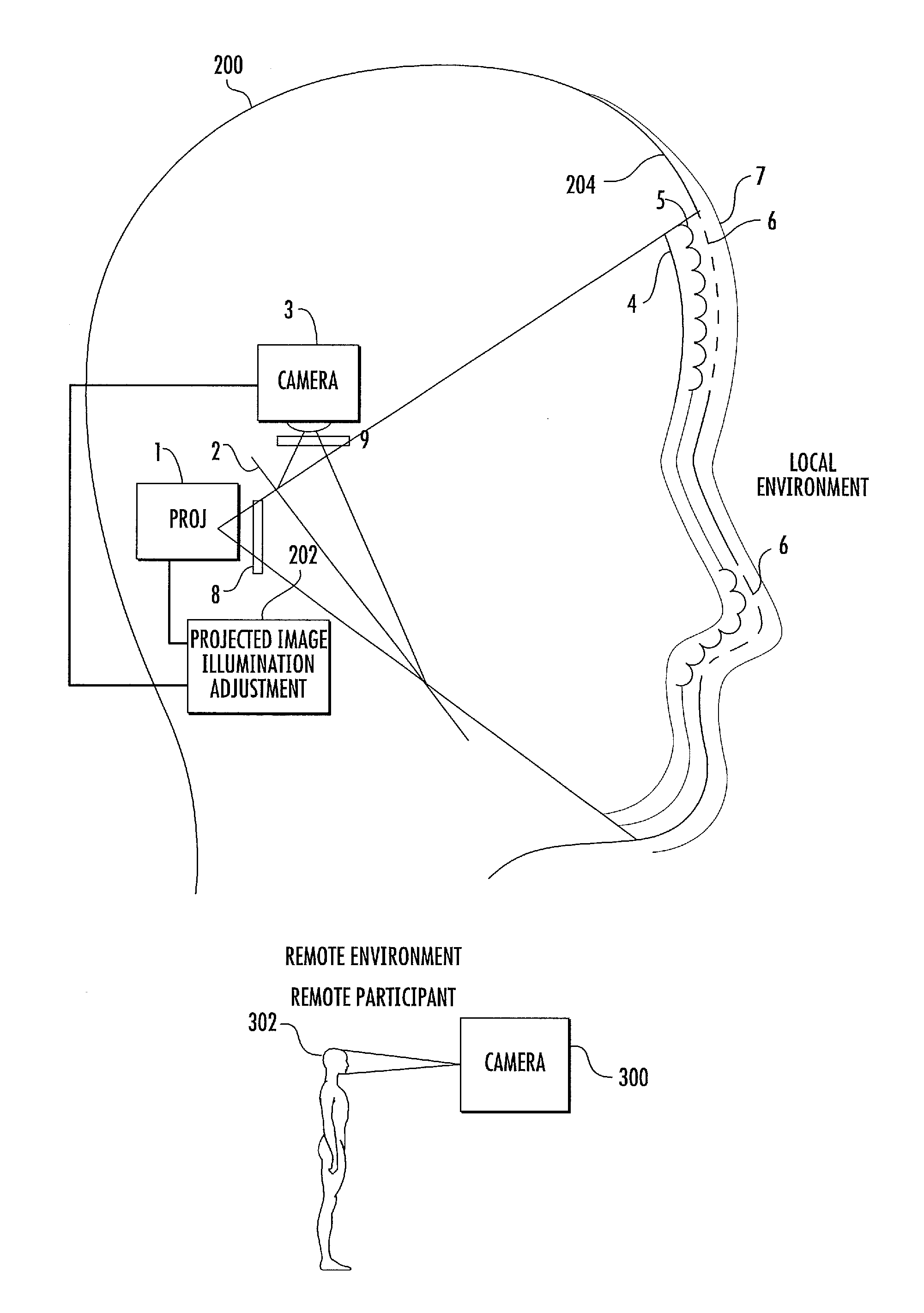
FIG. 2 is a diagram illustrating an augmented reality object suitable for spatial illumination and in a manner that compensates for ambient light according to an embodiment of the subject matter described herein. Referring to FIG. 2, augmented object 200 comprises a model of a human head, which may be part of a mannequin, as illustrated in FIG. 1. However, rather than illuminating augmented object 200 using a projector that does not compensate for ambient illumination, the subject matter described herein includes a camera that measures augmented illumination and a projector illumination adjustment module that automatically adjusts projector illumination based on the measured ambient illumination.
In FIG. 2, augmented reality object 200 includes a projector 1 for projecting desired images onto an augmented surface. For example, projector 1 may project video images of a human face onto the augmented object 200. The video images may be captured in a remote environment using a camera 300 that obtains video images of a remote participant 302 to a meeting. The remote environment may be a different room, a different building, or other different physical location from the local environment of augmented object 200. Camera 300 may be communicatively coupled to projector 1 so that projector 1 can re-project the images obtained from camera 300. In the illustrated example, projector 1 illuminates augmented reality object 200 from within augmented reality object 200.
Augmented reality object 200 further includes a camera 3 for measuring ambient illumination in the local environment. The ambient illumination may be caused by light sources, such as ceiling mounted lights or natural lighting in the local environment. A beam splitter 2 allows camera 3 to measure the ambient illumination. In FIG. 2, augmented reality object 200 includes a projection surface 204 in which is formed arrays 6 of apertures through which the projected image is output into the local environment.
Augmented surface 204 may be covered with non-reflecting flat black coating except for aperture arrays 6, in a manner similar to the technique described in U.S. Pat. No. 6,970,289 B1 (Screen for Rear Projection Display), the disclosure of which is incorporated herein by reference in its entirety. In front of this coating is a transparent protective layer 7. Behind this coating is a layer 5 of tiny lenslets, one behind each pinhole or aperture, which serve the function of concentrating the light falling onto each of the apertures from the projector 1 and focusing all that light through the associated pinhole. The back surface 4 of the lenslets layer 5 is shaped in such a way as to refract and direct the light coming in from the known angle to the desired direction that depends on the local angle of augmented surface 204 and the expected locations of the viewers of augmented surface 204. (For example an area on one side of the nose may be directed in one direction while a nearby area on the other side of the nose may be directed in another direction.) Adjacent lenslets (their rear and front curvatures, and distance between them) may be fabricated to point in different directions and have different fields of view to achieve the desired light distributions emanating from the augmented surface at each specific local area. The size of each lenslet should be several times smaller than a projector's pixel. As in the '289 Patent, the fabrication of the apertures can be achieved by first fabricating the lenslets layer 5 and then applying the flat black coating to the entire outer surface of the lenslets. Then a powerful energy source, like a scanning laser, is placed at the projector's location. Then the laser is scanned across the lenslets' surface. The focused energy should open apertures in the coating layer at precisely the same places where, later, light from the projector will exit.
In one embodiment of the subject matter described herein, lenslets layer 5 can be constructed along the complex curved surfaces of the augmented object. The shape, size, depth, and orientation of the lenslets can be designed to optimize the distribution of light emanating from various areas of the augmented surface, optimized for the desired appearance of the surface, and optimized also for the location and distribution of the expected viewers of the augmented surface making the apparent lighting on the augmented surface appear to be the same (or perhaps arbitrarily different) as the ambient lighting in the rest of the local environment may be achieved by constantly measuring the ambient light falling on various local areas of the augmented surface. As stated above, this ambient light is measured by placing a camera (3 in FIG. 2) inside the surface at the same optical location as projector 1. This can be achieved by placing beam splitter 2 in the optical path. As illustrated in FIG. 2, beam splitter 2 allows camera 3 to view ambient illumination of object 200 through aperture arrays 6 and to be physically offset from projector 1 so as not to block the projected image from being output through aperture arrays 6. To avoid the projector light overpowering the camera sensor, a solid state shutter 8 may be placed in front of the projector 1 and another solid state shutter 9 may be placed in front of the camera 3. At some regular rate (such as 60 Hz), the light from projector 1 is blocked by shutter 8 for a short fraction of the frame projector time and shutter 9 in front of the camera 3 is opened and the light coming in through the apertures is measured. The measurement of the ambient lighting on the augmented surface and the adjustment of the lighting of the projected image may be achieved by a projected image illumination adjustment module 202, which may be implemented in software in combination with hardware and/or firmware on a computer coupled to camera 3 and projector 1.
Projected image illumination adjustment module 202 may include a processor and associated memory for measuring the ambient light and adjusting the illumination light output from projector 1 based on the measured ambient light. Thus, projected image illumination adjustment module 202 may configure its associated processor to be a special purpose computer that improves the technological field of spatial illumination of augmented reality objects.
Not just the amount of ambient light can be measured, but since the precise geometry of the augmented surface is known, the directionality of the ambient light can also be estimated. The estimation of the directionality of the ambient light may also be performed by projected image illumination adjustment module 202 and used to adjust the directionality of the illumination of the projected image.
The size of the apertures (determined by the design of the lenslets surfaces and the power and ablation characteristics of the laser) can be changed to balance the needs of the camera for more light coming in, with the needs of the projection system to minimize reflection of ambient light off the augmented surface.
In order to take advantage of the camera-captured ambient illumination data, the overall system has to become more sophisticated about the capture of the image(s) that are to be projected onto the augmented surface. For example, consider the example of FIG. 1, where a remote live individual may be speaking, and the video stream of his face (talking) is projected onto the head-shape of the augmented surface. The problem is to capture the video images in such a way as to be able to "remove" his local lighting in the remote environment and "add" the lighting of the local ambient environment of the augmented surface (the surface onto which his video is projected). This is the classic relighting problem, with many excellent techniques. Rapid advances in higher speed cameras, LED lighting, and inexpensive commodity depth cameras (such as Kinect) make this capture of the user's lighting environment ever easier. The lighting of the environment of the captured video image may also be input to the projected image illumination adjustment module and used to adjust the illumination of the projected image.
FIG. 3 is a flow chart illustrating an exemplary process for illuminating a spatial augmented reality object according to an embodiment of the subject matter described herein. Referring to FIG. 3, in step 400, images to be displayed on an augmented reality object are captured. For example, one or more cameras 300 located in a remote environment from the augmented reality object may capture video images of a remote participant to a meeting or other event. In step 402, ambient illumination is measured in the local environment of the augmented reality object. The ambient illumination may be measured by camera 3 located within augmented reality object 200 or by a separate camera located in the local environment of augmented reality object 200. In step 404, illumination of the captured video images is adjusted based on the measured ambient illumination. In one example, the illumination of the captured video image may be modified to match the illumination of the local environment of the augmented reality object 200. Such matching may be achieved by removing the illumination created by the remote environment and then relighting the captured video image from the direction and with the intensity of the illumination in the local environment. In step 406, the illumination adjusted captured video image is projected on to the projection surface of the augmented reality object. For example, a projector which may be located within the augmented reality object may project the illumination adjusted image onto the illumination surface via lenslets layer 5 and pinhole arrays 6.
In an alternate implementation, projector 1 may illuminate the augmented reality object from the front or user facing side.
It will be understood that various details of the presently disclosed subject matter may be changed without departing from the scope of the presently disclosed subject matter. Furthermore, the foregoing description is for the purpose of illustration only, and not for the purpose of limitation.
* * * * *
References
D00000
D00001
D00002
D00003
XML
uspto.report is an independent third-party trademark research tool that is not affiliated, endorsed, or sponsored by the United States Patent and Trademark Office (USPTO) or any other governmental organization. The information provided by uspto.report is based on publicly available data at the time of writing and is intended for informational purposes only.
While we strive to provide accurate and up-to-date information, we do not guarantee the accuracy, completeness, reliability, or suitability of the information displayed on this site. The use of this site is at your own risk. Any reliance you place on such information is therefore strictly at your own risk.
All official trademark data, including owner information, should be verified by visiting the official USPTO website at www.uspto.gov. This site is not intended to replace professional legal advice and should not be used as a substitute for consulting with a legal professional who is knowledgeable about trademark law.