Appliance for receiving radio frequency signals, usable in particular for the management of uplink signals
Notargiacomo
U.S. patent number 10,320,432 [Application Number 15/319,729] was granted by the patent office on 2019-06-11 for appliance for receiving radio frequency signals, usable in particular for the management of uplink signals. This patent grant is currently assigned to Teko Telecom S.r.l.. The grantee listed for this patent is TEKO TELECOM S.R.L.. Invention is credited to Massimo Notargiacomo.

| United States Patent | 10,320,432 |
| Notargiacomo | June 11, 2019 |
Appliance for receiving radio frequency signals, usable in particular for the management of uplink signals
Abstract
The appliance for receiving radio frequency signals, usable in particular for the management of uplink signals, comprises an input port of a radio frequency input signal, an amplification unit connected to the input port an output port connected to the amplification unit, an adjustable notch filter operatively connected to the amplification unit, a detection unit of the interference frequency of a disturbance signal of the input signal, an adjustment unit operatively connected to the adjustable notch filter and to the detection unit and able to adjust the central frequency of the adjustable notch filter on the interference frequency.
| Inventors: | Notargiacomo; Massimo (Castel San Pietro Terme, IT) | ||||||||||
|---|---|---|---|---|---|---|---|---|---|---|---|
| Applicant: |
|
||||||||||
| Assignee: | Teko Telecom S.r.l. (Castel San
Pietro Terme, IT) |
||||||||||
| Family ID: | 51358002 | ||||||||||
| Appl. No.: | 15/319,729 | ||||||||||
| Filed: | June 15, 2015 | ||||||||||
| PCT Filed: | June 15, 2015 | ||||||||||
| PCT No.: | PCT/IB2015/054514 | ||||||||||
| 371(c)(1),(2),(4) Date: | December 16, 2016 | ||||||||||
| PCT Pub. No.: | WO2015/193792 | ||||||||||
| PCT Pub. Date: | December 23, 2015 |
Prior Publication Data
| Document Identifier | Publication Date | |
|---|---|---|
| US 20170149464 A1 | May 25, 2017 | |
Foreign Application Priority Data
| Jun 19, 2014 [IT] | MO2014A0181 | |||
| Current U.S. Class: | 1/1 |
| Current CPC Class: | H04B 1/1036 (20130101); H04B 2001/1063 (20130101) |
| Current International Class: | H04B 1/10 (20060101) |
References Cited [Referenced By]
U.S. Patent Documents
| 6035213 | March 2000 | Tokuda |
| 2006/0035620 | February 2006 | Millard |
| 2007/0047681 | March 2007 | Chan |
| 2007/0153878 | July 2007 | Filipovic |
| 2007/0262817 | November 2007 | Ciccarelli |
| 2008/0224792 | September 2008 | Nielsen |
| 2013/0035050 | February 2013 | Gao |
| 2013/0070875 | March 2013 | Kuan |
| 2013/0115904 | May 2013 | Kapoor |
| 2014/0106697 | April 2014 | Wang |
| 2711735 | Mar 2014 | EP | |||
Other References
|
European Search Report dated Feb. 6, 2015 from Italian Patent Application No. MO2014A000181 filed Jun. 19, 2014. cited by applicant . Intemational Search Report and Written Opinion dated Aug. 21, 2015 from International Patent Application No. PCT/IB2015/054514 filed Jun. 15, 2015. cited by applicant. |
Primary Examiner: Vo; Nguyen T
Attorney, Agent or Firm: Tingey; David B. Keller; Bryant J. Kirton McConkie
Claims
The invention claimed is:
1. An appliance for receiving radio frequency signals, comprising: an input port of a radio frequency input signal; a first amplification unit connected to said input port; a second amplification unit connected to said input port; an output port connected to said first amplification unit and said second amplification unit; an adjustable notch filter operatively connected to said first amplification unit and said second amplification unit, wherein said adjustable notch filter is arranged upstream of said second amplification unit so as to be configured to eliminate strong interference in said radio frequency input signal, and wherein said adjustable notch filter is arranged downstream of said first amplification unit so as to be configured to limit a noise figure of said radio frequency input signal; a first bypass connected to said first amplification unit; a second bypass connected to said second amplification unit, wherein said first bypass and said second bypass are operable to alternatively select said first amplification unit or said second amplification unit; a detection unit of an interference frequency of a disturbance signal of said input signal, wherein said detection unit comprises a spectrum analyzer able to receive at input said input signal and able to return at output spectral characteristics of said input signal and a monitoring unit operatively connected to said spectrum analyzer to receive said spectral characteristics and able to determine said interference frequency starting from said spectral characteristics of said input signal; and an adjustment unit operatively connected to said adjustable notch filter and to said detection unit and able to adjust a central frequency of said adjustable notch filter on said interference frequency.
2. The appliance according to claim 1, wherein said adjustable notch filter comprises a plurality of notch filters with different technical characteristics, said plurality of notch filters adaptable to be combined together so as to adjust said central frequency of said adjustable notch filter obtained from said interference frequency and so as to adjust an eliminated band to only a band of said disturbance signal.
3. The appliance according to claim 2, wherein said technical characteristics of said plurality of notch filters are selected from a group consisting of: narrowband, broadband, fixed bandwidth, variable bandwidth, order, central frequency, and a combination thereof.
4. The appliance according to claim 1, wherein said first amplification unit comprises a low noise amplifier.
5. The appliance according to claim 1, comprising an analog/digital converter connected to said output of at least one of said first amplification unit, said second amplification unit, and said adjustable notch filter.
6. The appliance according to claim 1, wherein selection of said first amplification unit is configured to eliminate strong interference in the radio frequency input signal, and wherein selection of said second amplification unit is configured to limit the noise figure of the radio frequency input signal.
7. The appliance according to claim 1, wherein said second amplification unit comprises a low noise amplifier.
8. A receiver device for receiving radio frequency signals, comprising: an input port of a radio frequency input signal; a first amplification unit connected to said input port; a second amplification unit connected to said input port; an output port connected to said first amplification unit and said second amplification unit; a first bypass connected to said first amplification unit; a second bypass connected to said second amplification unit; and an adjustable notch filter operatively connected to said first amplification unit and said second amplification unit and adjustable depending on an interference frequency of a disturbance signal of said input signal, said adjustable notch filter configured to receive said interference frequency without said input signal having previously passed through said adjustable notch filter, wherein said adjustable notch filter is arranged upstream of said second amplification unit so as to be configured to eliminate strong interference in said radio frequency input signal, wherein said adjustable notch filter is arranged downstream of said first amplification unit so as to be configured to limit a noise figure of said radio frequency input signal, and wherein said first bypass and said second bypass are operable to alternatively select said first amplification unit or said second amplification unit.
9. The appliance according to claim 8, wherein said first amplification unit comprises a low noise amplifier.
10. The appliance according to claim 8, wherein said second amplification unit comprises a low noise amplifier.
11. A receiver device for receiving radio frequency signals, comprising: an input port of a radio frequency input signal; a first amplification unit connected to the input port; a second amplification unit connected to the input port; an output port connected to the first amplification unit and the second amplification unit; a first bypass connected to the first amplification unit; a second bypass connected to the second amplification unit; and an adjustable notch filter operatively connected to the first amplification unit and the second amplification unit, wherein the adjustable notch filter is arranged upstream of the second amplification unit so as to be configured to eliminate strong interference in the radio frequency input signal, wherein the adjustable notch filter is arranged downstream of the first amplification unit so as to be configured to limit a noise figure of the radio frequency input signal, and wherein the first bypass and the second bypass are operable to alternatively select the first amplification unit to eliminate strong interference in the radio frequency input signal, or the second amplification unit to limit the noise figure of the radio frequency input signal.
12. The device according to claim 11, wherein said first amplification unit comprises a low noise amplifier.
13. The device according to claim 11, wherein said second amplification unit comprises a low noise amplifier.
Description
TECHNICAL FIELD
The present invention relates to an appliance for receiving radio frequency signals, usable in particular for the management of uplink signals.
BACKGROUND ART
It is known that with reference to any type of analogue or digital receiver, the quality of the uplink is considerably limited by the presence of interference which can disturb the signal processing on the receiving chain.
The presence of a strong input signal can in fact activate the ALC (Automatic Level Control) circuit, which is responsible for automatically adjusting the signal power in order to maintain it constant even in the event of fast variations in the input signal.
This can inevitably lead to an indiscriminate reduction of the disturbed input signal or, with reference to a digital receiver, it may cause the saturation of the ADC (Analog to Digital Converter) circuit, with the consequent incorrect digitalisation of the signal.
Therefore, it is of fundamental importance to be able to efficiently cancel the interference on the uplink signal.
In particular, the filters used must necessarily have an extremely selective frequency response, in order to ensure the elimination exclusively of the part of interference relating to the uplink signal.
DESCRIPTION OF THE INVENTION
The main aim of the present invention is to provide an appliance for receiving radiofrequency signals, usable in particular for the management of uplink signals, which allows to reduce or eliminate a particular frequency from an input signal, while maintaining substantially unchanged the other frequencies within the signal spectrum.
Another object of the present invention is to provide an appliance for receiving radiofrequency signals, usable in particular for the management of uplink signals, which allows to overcome the mentioned drawbacks of the prior art within the ambit of a simple, rational, easy and effective to use as well as affordable solution.
The above mentioned objects are achieved by the present appliance for receiving radiofrequency signals, usable in particular for the management of uplink signals, according to claim 1.
BRIEF DESCRIPTION OF THE DRAWINGS
Other characteristics and advantages of the present invention will become better evident from the description of five preferred, but not exclusive embodiments of an appliance for receiving radiofrequency signals, usable in particular for the management of uplink signals, illustrated by way of an indicative but non-limitating example in the accompanying drawings, in which:
FIG. 1 is a block diagram showing a possible first embodiment of the appliance according to the invention;
FIG. 2 is a block diagram showing a possible second embodiment of the appliance according to the invention;
FIG. 3 is a block diagram showing a possible third embodiment of the appliance according to the invention;
FIG. 4 is a block diagram showing a possible fourth embodiment of the appliance according to the invention;
FIG. 5 is a block diagram showing a possible fifth embodiment of the appliance according to the invention.
EMBODIMENTS OF THE INVENTION
With particular reference to such illustrations, globally indicated with A is an appliance for receiving radiofrequency signals, usable in particular for the management of uplink signals.
In particular, the appliance A comprises a receiver device D, the type of a Remote Unit or similar device, having an input port IN, connectable to at least an antenna ANT and able to receive a radio frequency input signal S.sub.IN, an amplification unit LNA connected to the input port IN and an output port OUT connected to the amplification unit LNA.
Preferably, the amplification unit LNA is made up of a low noise amplifier. Advantageously, the receiver device D comprises an adjustable notch filter F.sub.n operatively connected to the amplification unit LNA.
Furthermore, the appliance A comprises a detection unit DU of the interference frequency f.sub.i of at least a disturbance signal of the input signal S.sub.IN, and an adjustment unit CU operatively connected to the adjustable notch filter F.sub.n and to the detection unit DU and able to adjust the central frequency of the filter F.sub.n on the interference frequency f.sub.i and to adjust the bandwidth eliminated so as to eliminate the interference only, leaving unaltered the useful signal as much as possible.
In particular, the detection unit DU comprises a spectrum analyzer SA able to receive at input the input signal S.sub.IN and able to return at output the spectral characteristics of the input signal itself.
The detection unit DU can also comprise monitoring means M operatively connected to the output of the spectrum analyzer SA and able to determine the interference frequency starting from the spectral characteristics of the input signal S.sub.IN.
For example, these monitoring means can be implemented by means of a suitable software programme.
In practice, therefore, the information provided by a spectrum analyzer is used to adjust the adjustable notch filter F.sub.n positioned in specific positions in the uplink chain of a receiver device D, in order to eliminate strong interference. In particular, the central frequency and the bandwidth of the adjustable notch filter F.sub.n are adjusted depending on the specific characteristics of the interference.
The spectrum analysis of the input signal S.sub.IN and, therefore, the detection of the interference frequency f.sub.i, as well as the adjustment of the adjustable notch filter F.sub.n, can be done: manually: an operator monitors the information provided by the spectrum analyzer SA and adjusts the filter F.sub.n accordingly; automatically: the monitoring means M, implemented by means of a suitable software programme, are used to monitor the output of the spectrum analyzer SA to identify the presence of interference and determine its characteristics.
In the second case, in particular, the interference may be detected by scanning the uplink band using different methodologies, such as: receiving of information on interference from the Base Radio Station (Base Station--BS); by means of an uplink signal autocorrelation function, and by means of the recognition of a predefined scheme of interference parameters (frequency, bandwidth, etc.); by means of the analysis of the quality level of the radio frequency signal.
The spectrum analyzer SA and the detection unit DU can be located on the Master Unit (MU) side.
Conveniently, in this case the conventional communication link already present between the Master Unit and the Remote Unit can be used to transmit information to the adjustment unit CU.
The integration of the detection unit DU and the adjustment unit CU directly on the Remote Unit (RU) side within the receiver device D cannot however be ruled out.
Advantageously, furthermore, the adjustable notch filter F.sub.n comprises a plurality of notch filters, not shown in the illustrations, with different technical characteristics and that may be combined together so as to center the central frequency on the interference frequency f.sub.i and to adjust the eliminated bandwidth so as to eliminate the interference only, leaving unaltered the useful signal as much as possible.
Specifically, the technical characteristics of the plurality of notch filters can be selected from the group comprising: narrowband, broadband, fixed bandwidth, variable bandwidth, order, central frequency.
In this way, therefore, it is possible to use the series of notch filters to obtain a notch filter centred on the specific interference frequency.
Advantageously, the adjustable notch filter F.sub.n can be positioned in two different positions along the uplink chain: upstream of the low noise amplifier LNA; downstream of the low noise amplifier LNA.
Referring to a first embodiment, illustrated in FIG. 1, the receiver device D is composed of an analogue Remote Unit wherein the adjustable notch filter F.sub.n is positioned upstream of the low noise amplifier LNA.
In this case, the receiver device D comprises: an input filter F.sub.IN, the type of a DPX filter or the like, connected to the input port IN; the adjustable notch filter F.sub.n, connected downstream of the input filter F.sub.IN; the low noise amplifier LNA, connected downstream of the adjustable notch filter F.sub.n; an output filter F.sub.OUT, the type of an analogue band pass filter, connected downstream of the low noise amplifier LNA; an electro-optic converter E/O, connected downstream of the output filter F.sub.OUT and upstream of the output port OUT.
In particular, the adjustable notch filter F.sub.n is arranged upstream of the low noise amplifier LNA if there is strong interference, in order to eliminate such interference and guarantee a dynamic, strong signal.
It should be noted that inserting the adjustable notch filter F.sub.n at the head of the amplification chain leads to the increase in NF (Noise Figure) equal to the IL (Insertion Loss) of the filter F.sub.n. Therefore, this solution is advisable if the need to limit the noise figure NF is greater than the need to eliminate strong interference.
With reference to a second embodiment, illustrated in FIG. 2, the receiver device D is made up of a digital Remote Unit wherein the adjustable notch filter F.sub.n is positioned upstream of the low noise amplifier LNA.
In this case, the only difference with respect to the analogue solution described above consists in the presence of an analogue/digital A/D converter connected directly downstream of the low noise amplifier LNA and in the presence of a digital output filter F.sub.OUT interposed between the analogue/digital A/D converter and the electro-optic E/O converter.
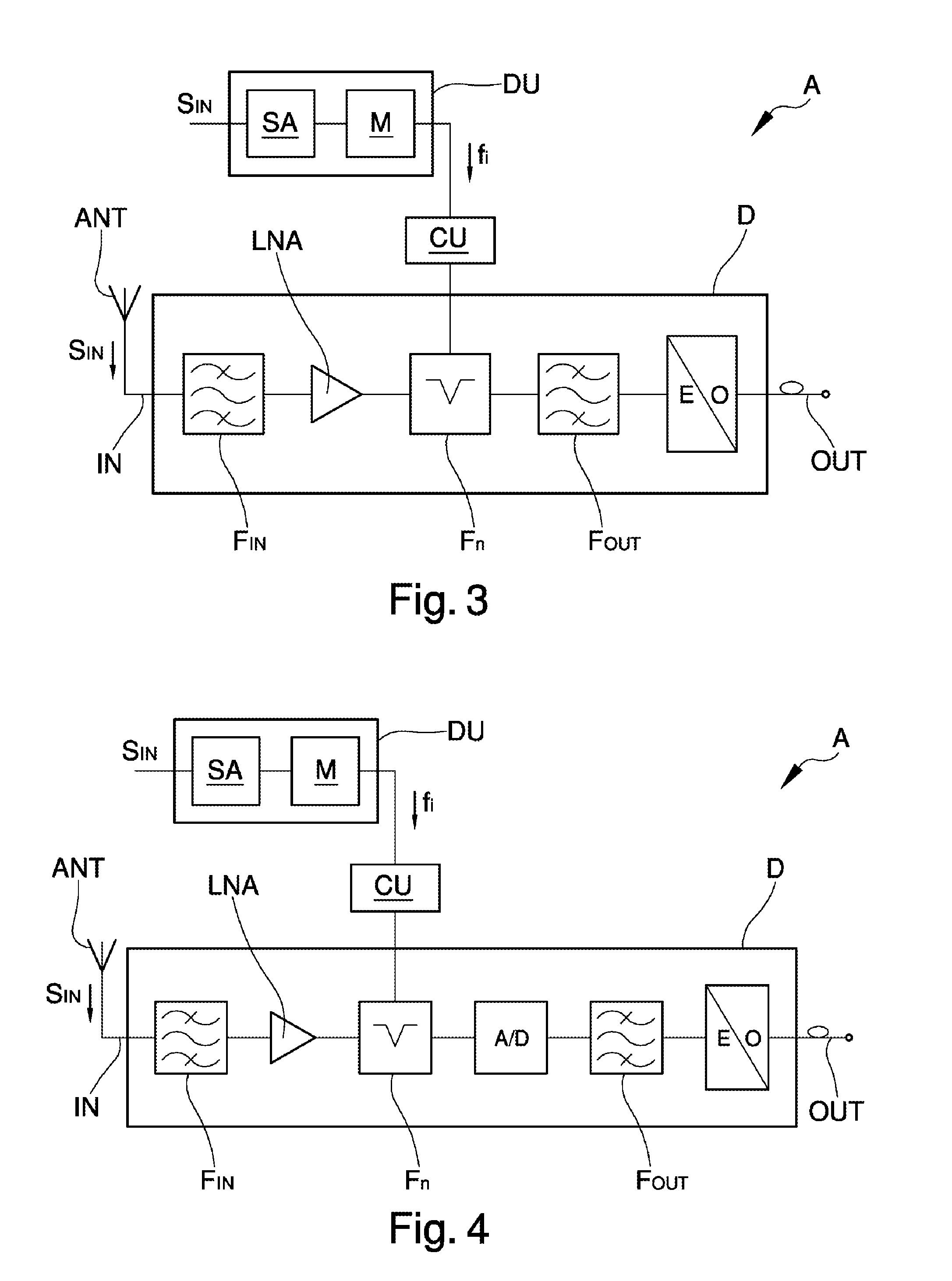
With reference to a third embodiment, illustrated in FIG. 3, the receiver device D is made up of an analogue Remote Unit wherein the adjustable notch filter F.sub.n is positioned downstream of the low noise amplifier LNA, before the output filter F.sub.OUT.
In particular, the adjustable notch filter F.sub.n is positioned downstream of the low noise amplifier LNA if the interference is present but the limitation of an acceptable NF is more important.
In this case, the good linearity of the amplifier LNA is exploited, as it is strong with low-medium power signals.
With reference to a fourth embodiment, illustrated in FIG. 4, the receiver device D is made up of a digital Remote Unit wherein the adjustable notch filter F.sub.n is positioned downstream of the low noise amplifier LNA, before the output filter F.sub.OUT.
In this case, the only difference with respect to the analogue solution described above consists in the presence of an analogue/digital A/D converter connected directly downstream of the adjustable notch filter F.sub.n and in the presence of an analogue output filter F.sub.OUT interposed between the analogue/digital A/D converter and the electro-optic E/O converter.
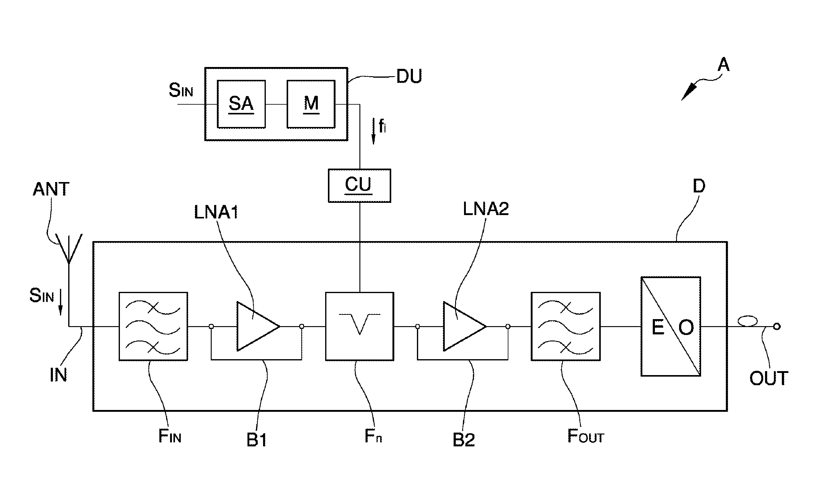
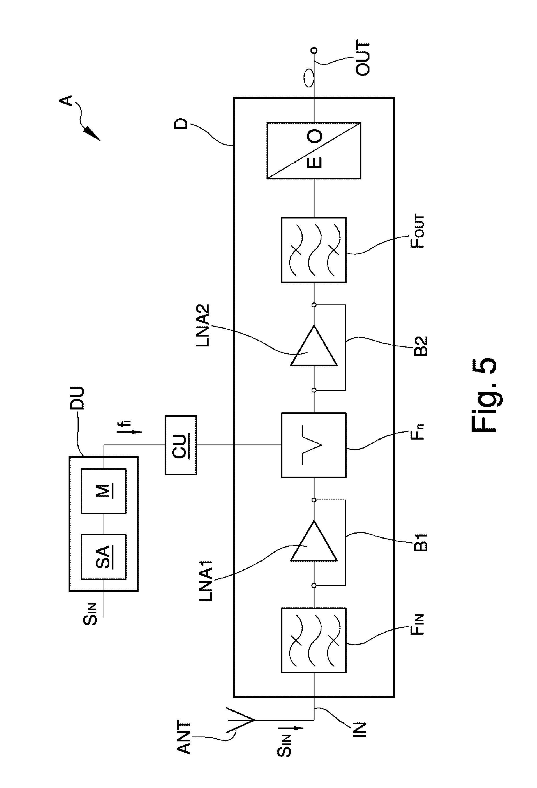
A possible further evolution of the receiver device D, schematically shown in FIG. 5, envisages the presence of a first low noise amplifier LNA1 and of a second low noise amplifier LNA2 arranged upstream and downstream respectively, of the adjustable notch filter F.sub.n together with the use of suitable selection means between the first and second low noise amplifiers LNA1 or LNA2.
In particular, such selection means may comprise a first bypass B1 and a second bypass B2, connected to the first and to the second low noise amplifiers LNA1 and LNA2 respectively, and operable alternatively to select one or the other.
In practice, therefore, the selection of the first low noise amplifier LNA1 arranged upstream of the adjustable notch filter F.sub.n or of the second low noise amplifier LNA2 positioned downstream of the adjustable notch filter F.sub.n is made according to the compromise between the need to reduce the impact of the interference signal and the need to limit the noise figure NF.
This is the optimal solution, as it allows to limit the noise figure in the presence of low/medium power interference (inserting the adjustable notch filter F.sub.n after the amplifier LNA) and to eliminate strong interference before the amplification stage (inserting the adjustable notch filter F.sub.n before the amplifier LNA).
The operation of the appliance A according to the invention is described briefly below.
First of all, by means of the spectrum analyzer SA the presence of an interference in the input signal S.sub.IN is detected.
Subsequently, an operator or the monitoring means M, implemented by means of a suitable software programme, extract the interference characteristics (central frequency, bandwidth, etc.).
Consequently, an operator or the adjustment unit CU, implemented by means of a suitable software programme, adjust the series of notch filters to obtain an adjustable notch filter F.sub.n set to the specific characteristics of interference.
It has in practice been ascertained how the described invention achieves the proposed objects.
In particular, the fact is underlined that the use of the adjustable notch filter allows to reduce or eliminate a particular frequency from an input signal, at the same time maintaining the other frequencies within the signal spectrum substantially unchanged.
* * * * *
D00000
D00001
D00002
D00003
XML
uspto.report is an independent third-party trademark research tool that is not affiliated, endorsed, or sponsored by the United States Patent and Trademark Office (USPTO) or any other governmental organization. The information provided by uspto.report is based on publicly available data at the time of writing and is intended for informational purposes only.
While we strive to provide accurate and up-to-date information, we do not guarantee the accuracy, completeness, reliability, or suitability of the information displayed on this site. The use of this site is at your own risk. Any reliance you place on such information is therefore strictly at your own risk.
All official trademark data, including owner information, should be verified by visiting the official USPTO website at www.uspto.gov. This site is not intended to replace professional legal advice and should not be used as a substitute for consulting with a legal professional who is knowledgeable about trademark law.