Giant magnetoresistive sensor having horizontal stabilizer
McKinstry
U.S. patent number 10,317,481 [Application Number 14/822,108] was granted by the patent office on 2019-06-11 for giant magnetoresistive sensor having horizontal stabilizer. This patent grant is currently assigned to Oracle International Corporation. The grantee listed for this patent is Oracle International Corporation. Invention is credited to Kevin D. McKinstry.


| United States Patent | 10,317,481 |
| McKinstry | June 11, 2019 |
Giant magnetoresistive sensor having horizontal stabilizer
Abstract
A giant magnetoresistive (GMR) sensor for reading information from a magnetic storage medium has a first non-magnetoresistive layer, a first magnetoresistive layer formed on the first non-magnetoresistive layer, a second non-magnetoresitive layer formed on the first magnetoresistive layer, a second magnetoresistive layer formed on the second non-magnetoresistive layer, and a third non-magnetoresistive layer formed on the second magnetoresistive layer. The first non-magnetoresistive layer is provided with a single step on a surface of the first non-magnetoresistive layer. The step has an edge extending in a direction substantially parallel to a plane of a working surface of the GMR sensor.
| Inventors: | McKinstry; Kevin D. (Westminster, CO) | ||||||||||
|---|---|---|---|---|---|---|---|---|---|---|---|
| Applicant: |
|
||||||||||
| Assignee: | Oracle International
Corporation (Redwood Shores, CA) |
||||||||||
| Family ID: | 47390450 | ||||||||||
| Appl. No.: | 14/822,108 | ||||||||||
| Filed: | August 10, 2015 |
Prior Publication Data
| Document Identifier | Publication Date | |
|---|---|---|
| US 20150348575 A1 | Dec 3, 2015 | |
Related U.S. Patent Documents
| Application Number | Filing Date | Patent Number | Issue Date | ||
|---|---|---|---|---|---|
| 13170625 | Jun 28, 2011 | 9134386 | |||
| Current U.S. Class: | 1/1 |
| Current CPC Class: | G11B 5/398 (20130101); G01R 33/093 (20130101); Y10T 29/4902 (20150115) |
| Current International Class: | G11B 5/39 (20060101); G01R 33/09 (20060101) |
| Field of Search: | ;360/324 ;428/811,811.3 ;134/134 |
References Cited [Referenced By]
U.S. Patent Documents
| 4477794 | October 1984 | Nomura et al. |
| 4566050 | January 1986 | Beam et al. |
| 4613918 | September 1986 | Kanai et al. |
| 4663683 | May 1987 | Youda et al. |
| 5287238 | February 1994 | Baumgart et al. |
| 5527626 | June 1996 | Gijs et al. |
| 5589278 | December 1996 | Kamijo |
| 5657191 | August 1997 | Yuan |
| 5896251 | April 1999 | Ohsawa et al. |
| 6118623 | September 2000 | Fatula, Jr. et al. |
| 6168860 | January 2001 | Daughton |
| 6278594 | August 2001 | Engel et al. |
| 7118814 | October 2006 | Arnold et al. |
| 7227726 | June 2007 | Denison et al. |
| 7256969 | August 2007 | Arnold |
| 7492554 | February 2009 | Breuer et al. |
| 7495871 | February 2009 | Nibarger et al. |
| 7545602 | June 2009 | McKinstry et al. |
| 7848052 | December 2010 | McKinstry et al. |
| 2002/0029462 | March 2002 | Spitzer et al. |
| 2007/0121249 | May 2007 | Parker |
| 2008/0266711 | October 2008 | Nibarger et al. |
| 2008/0297954 | December 2008 | Aiso |
| 2009/0046393 | February 2009 | Davey et al. |
| 2009/0147389 | June 2009 | Taratorin |
| 2009/0213495 | August 2009 | McKinstry et al. |
Other References
|
Transition from AMR to GMR Heads in Tape Recording by John P. Nibarger, presented at the THIC Meeting at the National Center for Atmospheric Research, Aug. 21-22, 2007 (available at www.thic.org/pdf/August07/sun.Nibarger.pdf, accessed Jan. 11, 2018). pp. 1-30. cited by applicant. |
Primary Examiner: Tadayyon Eslami; Tabassom
Attorney, Agent or Firm: Invoke
Parent Case Text
CROSS-REFERENCE TO RELATED APPLICATION
This application is a divisional of U.S. patent application Ser. No. 13/170,625 filed on Jun. 28, 2011, the disclosure of which is incorporated in its entirety by reference herein.
Claims
What is claimed is:
1. A method for manufacturing a giant magnetoresistive (GMR) sensor for reading information from a magnetic storage medium, the GMR sensor having a working surface oriented proximate the magnetic storage medium during operation of the GMR sensor, the method comprising: forming a first non-magnetoresistive layer; forming a first magnetoresistive layer on the first non-magnetoresistive layer; forming a second non-magnetoresitive layer on the first magnetoresistive layer; forming a second magnetoresistive layer on the second non-magnetoresistive layer; providing the first non-magnetoresistive layer with only a single step on a surface thereof, the step providing a transitional surface in the first non-magnetoresistive layer between first and second levels of the surface of the first non-magnetoresistive layer and having an edge along a line formed by a junction of the transitional surface and the first level of the surface of the first non-magnetoresistive layer, the edge extending in a direction substantially parallel to a plane of the working surface of the GMR sensor; and providing the first magnetoresistive layer with only a single step on a surface thereof, the step provided on the surface of the first magnetoresistive layer being substantially coextensive with the step provided on the surface of the first non-magnetoresistive layer; wherein the single step provided on the surface of the first non-magnetoresistive layer and the single step provided on the surface of the first magnetoresistive layer each extend horizontally across substantially an entire width of the GMR sensor.
2. The method of claim 1 wherein the magnetic storage medium comprises a magnetic tape, the working surface of the GMR sensor comprises a tape bearing surface, and the edge of the step provided on the surface of the first non-magnetoresistive layer extends in a direction substantially parallel to a plane of the tape bearing surface of the GMR sensor.
3. The method of claim 1 further comprising providing each of the the first magnetoresistive layer, the second non-magnetoresistive layer, and the second magnetoresistive layer with a single step on a surface thereof, each step provided on the surface of each layer being substantially coextensive with the step proved on the surface of an adjacent layer.
4. The method of claim 1 wherein the single step provided on the surface of the first non-magnetoresistive layer is produced by a chemical process.
5. The method of claim 1 wherein the single step provided on the surface of the first non-magnetoresistive layer is produced by a mechanical process.
6. A method for manufacturing a giant magnetoresistive (GMR) sensor for reading information from a magnetic storage medium, the GMR sensor having a working surface oriented proximate the magnetic storage medium during operation of the GMR sensor, the method comprising: forming a plurality of non-magnetoresistive layers; forming a plurality of magnetoresistive layers interposed between the plurality of non-magnetoresistive layers; and providing each of the plurality of layers with only a single step on a surface thereof, each step on the surface of each layer being substantially coextensive with the step provided on the surface of an adjacent layer, each step providing a transitional surface in the associated layer between first and second levels of the surface of the associated layer and having an edge along a line formed by a junction of the transitional surface and the first level of the surface of the associated layer, the edge extending in a direction substantially parallel to a plane of the working surface of the GMR sensor; wherein each step provided on the surface of each of the plurality of layers extends horizontally across substantially an entire width of the GMR sensor.
7. The method of claim 6 wherein the magnetic storage medium comprises a magnetic tape, the working surface of the GMR sensor comprises a tape bearing surface.
8. The method of claim 6 wherein at least one of the steps provided on the surfaces of the plurality of layers is produced by a chemical process.
9. The method of claim 6 wherein at least one of the steps provided on the surfaces of the plurality of layers is produced by a mechanical process.
Description
TECHNICAL FIELD
The following relates to a giant magnetoresistive (GMR) sensor having a horizontal stabilizer provided therein.
BACKGROUND
Giant magnetoresistive (GMR) sensors used as read elements in magnetic data storage and retrieval systems need to operate in a linear and stable fashion. Especially when used as read elements in a multi-track read/write head in magnetic tape data storage and retrieval systems, GMR sensors also need to operate as close to equivalent to each other as possible.
GMR sensors, however, are unfortunately prone to defects which can cause instability and bias point changes during their operation in such data storage and retrieval systems. As a result, there exists a need for a GMR sensor that overcomes such problems. Such a GMR sensor would minimize the effects of such defects, thereby improving manufacturing yield and allowing the sensor to operate in a more stable fashion when used in data storage and retrieval systems.
More specifically, such a sensor would be built incorporating topographic features that provide equivalent magnetic fields large enough to minimize the effect of random manufacturing variations, thereby providing greater sensor equivalency in multi-track read/write heads. Such topographical features would comprise a step in a layer beneath the working surface of the GMR sensor. Such a step would be parallel to the working surface of the GMR sensor, such as the tape bearing surface of a GMR sensor in a magnetic tape data storage and retrieval system. Such a feature would provide for a GMR sensor which allows multi-track GMR heads to be built with better yield, better performance, and less sensor variation between tracks.
SUMMARY
According to one embodiment disclosed herein, a giant magnetoresistive (GMR) sensor for reading information from a magnetic storage medium is provided. The GMR sensor has a working surface oriented proximate the magnetic storage medium during operation of the GMR sensor. The GMR sensor comprises a first non-magnetoresistive layer, a first magnetoresistive layer formed on the first non-magnetoresistive layer, a second non-magnetoresitive layer formed on the first magnetoresistive layer, a second magnetoresistive layer formed on the second non-magnetoresistive layer, and a third non-magnetoresistive layer formed on the second magnetoresistive layer. The first non-magnetoresistive layer is provided with a single step on a surface of the first non-magnetoresistive layer, the step having an edge extending in a direction substantially parallel to a plane of the working surface of the GMR sensor.
According to another embodiment, a giant magnetoresistive (GMR) sensor is provided for reading information from a magnetic storage medium, the GMR sensor having a working surface oriented proximate the magnetic storage medium during operation of the GMR sensor. The GMR sensor comprises a plurality of sensor stack layers comprising a plurality of non-magnetoresistive layers, and a plurality of magnetoresistive layers interposed between the plurality of non-magnetoresistive layers. Each of the plurality of sensor stack layers is provided with a single step on a surface thereof, each step provided on the surface of each layer being substantially coextensive with the step provided on the surface of an adjacent layer. Each step has an edge extending in a direction substantially parallel to a plane of the working surface of the GMR sensor.
According to a further embodiment, a method for manufacturing a giant magnetoresistive (GMR) sensor for reading information from a magnetic storage medium is provided. The GMR sensor has a working surface oriented proximate the magnetic storage medium during operation of the GMR sensor. The method comprises forming a first non-magnetoresistive layer, forming a first magnetoresistive layer on the first non-magnetoresistive layer, and forming a second non-magnetoresitive layer on the first magnetoresistive layer. The method further comprises forming a second magnetoresistive layer on the second non-magnetoresistive layer, and forming a third non-magnetoresistive layer on the second magnetoresistive layer. The method still further comprises providing the first non-magnetoresistive layer with a single step on a surface of the first non-magnetoresistive layer, the step having an edge extending in a direction substantially parallel to a plane of the working surface of the GMR sensor.
A detailed description of these embodiments and accompanying drawings is set forth below.
BRIEF DESCRIPTION OF THE DRAWINGS
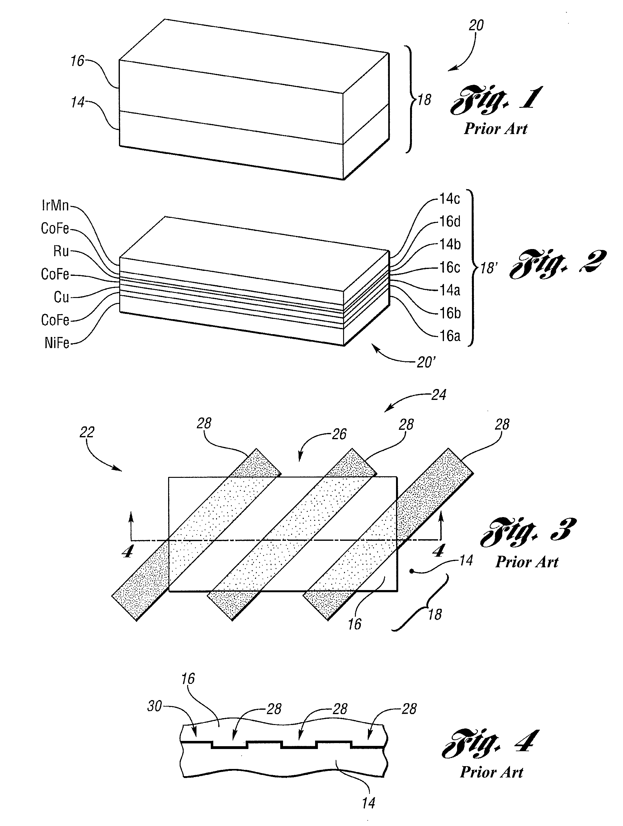
FIG. 1 is a perspective view of material layers for use in a prior art anisotropic magnetoresistive (AMR) sensor;
FIG. 2 is a perspective view of exemplary material layers for use in a giant magnetoresistive (GMR) sensor;
FIG. 3 is a top view of a prior art AMR sensor with a stabilizer pattern formed therein;
FIG. 4 is an edge-on view of the prior art AMR sensor depicted in FIG. 3, taken along the line 4-4 thereof showing the stabilizer pattern formed therein;
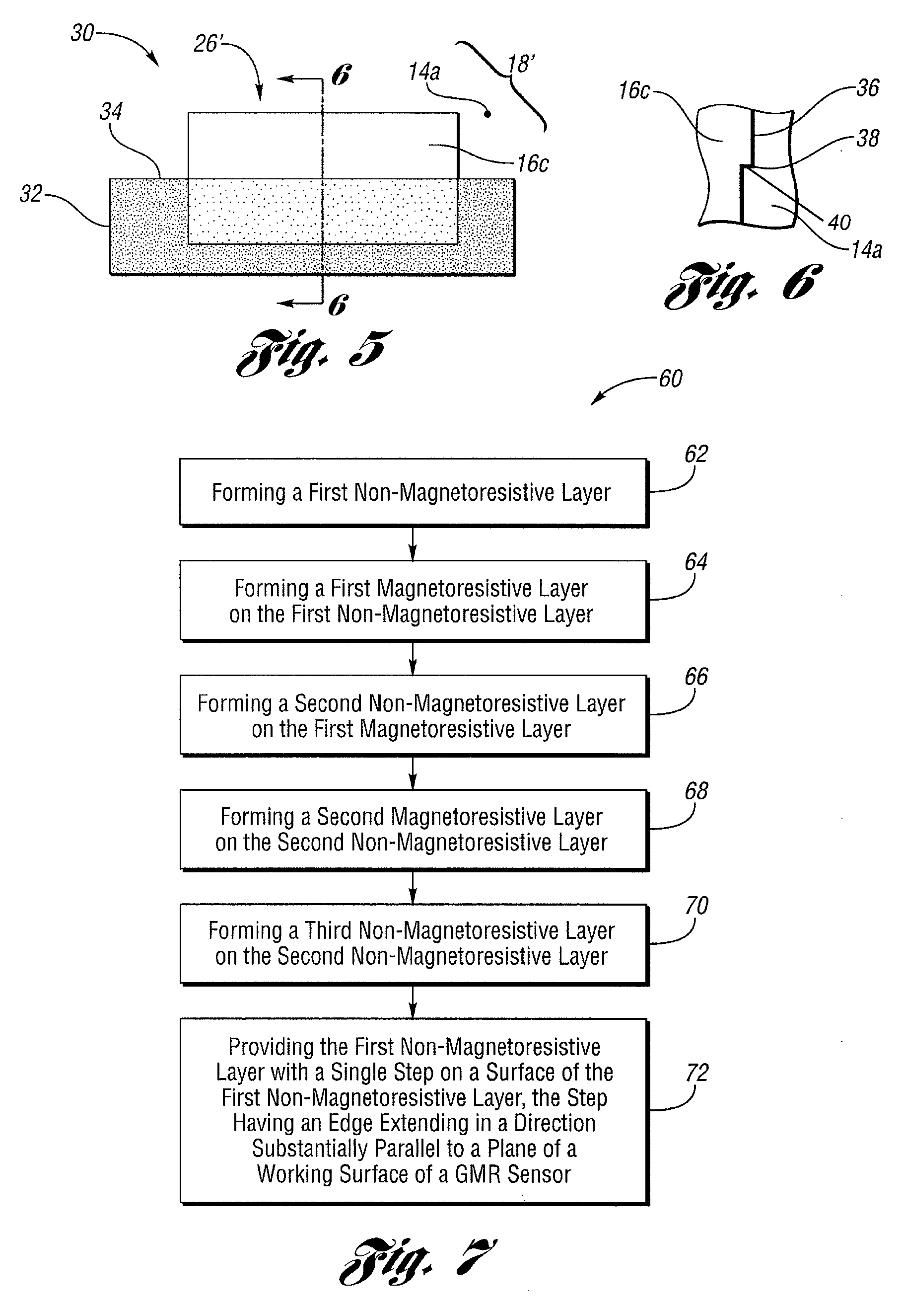
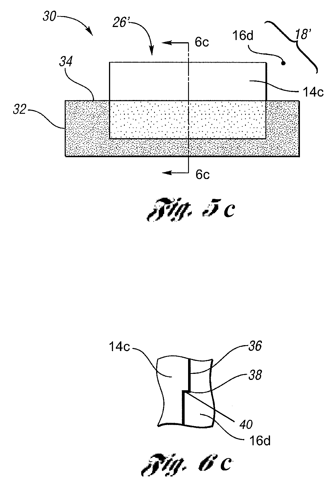
FIGS. 5, 5b and 5c are top views of an embodiment of the GMR sensor disclosed herein with a stabilizer pattern formed therein;
FIGS. 6, 6b and 6c are edge-on views of the embodiment of the GMR sensor disclosed herein and depicted in FIGS. 5, 5b and 5c, taken along the lines 6-6, 6b-6b and 6c-6c thereof showing the stabilizer pattern formed therein;
FIG. 7 is an exemplary flowchart depicting an embodiment of a method for manufacturing a GMR sensor as disclosed herein;
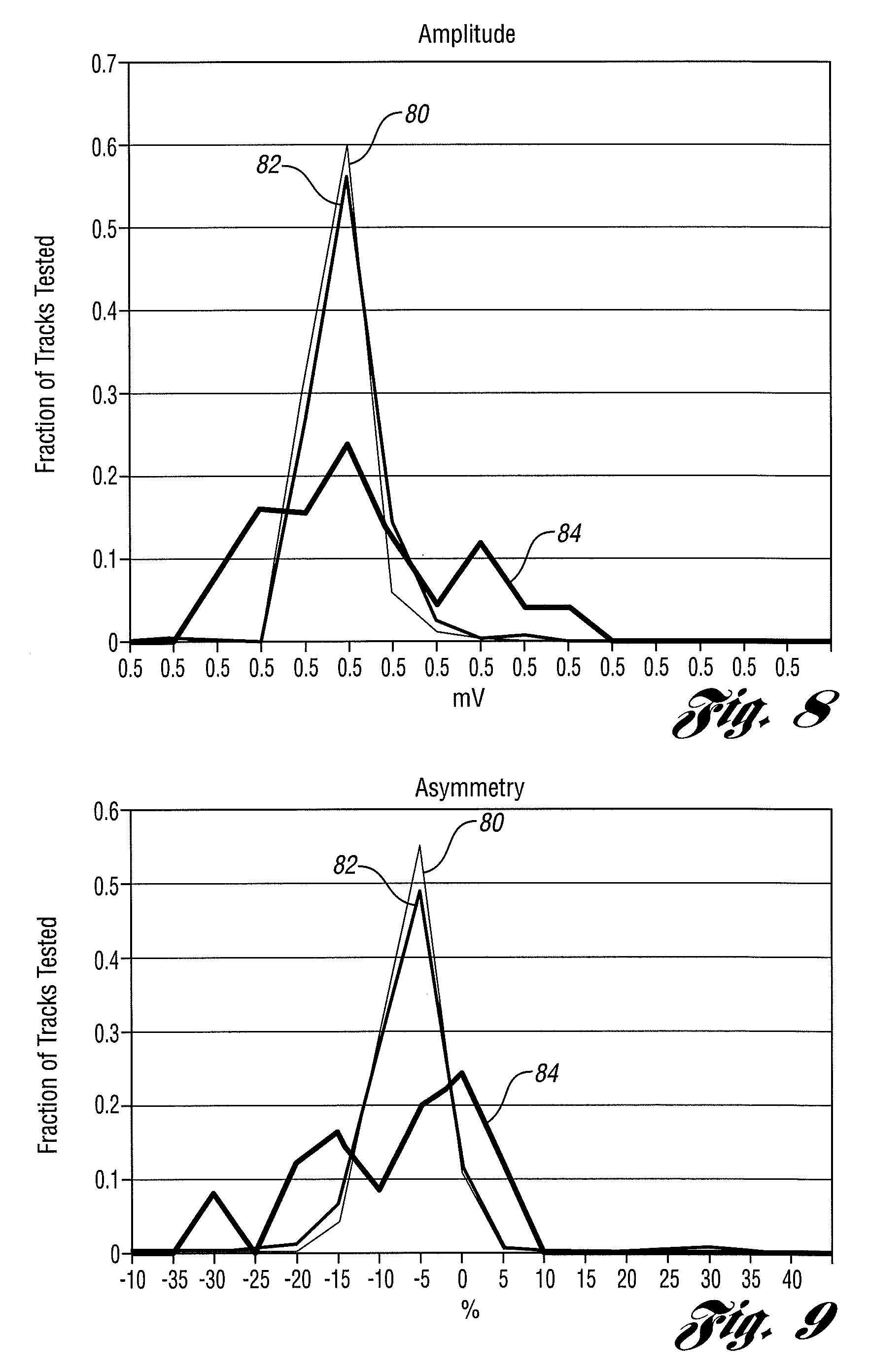
FIG. 8 is a plot depicting amplitude output for multi-sensor GMR heads having horizontal stabilizers as disclosed herein in comparison to a prior art multi-sensor GMR head without stabilization;
FIG. 9 is a plot depicting asymmetry for multi-sensor GMR heads having horizontal stabilizers as disclosed herein in comparison to a prior art multi-sensor GMR head without stabilization;
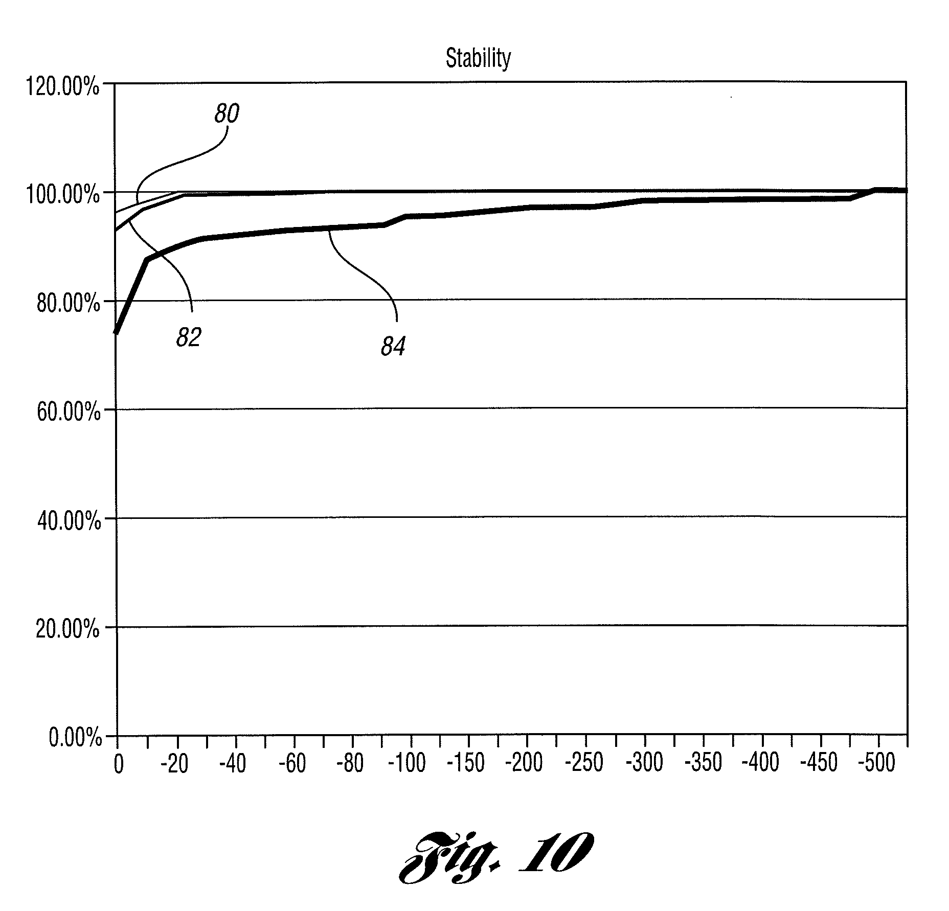
FIG. 10 is a plot depicting stability for multi-sensor GMR heads having horizontal stabilizers as disclosed herein in comparison to a prior art multi-sensor GMR head without stabilization;
FIG. 11 is a plot depicting Viterbi Quality Metric (VQM) for a multi-sensor GMR head having horizontal stabilizers as disclosed herein in comparison to a prior art multi-sensor GMR head without stabilization; and
FIG. 12 is a plot of block error rate for a multi-sensor GMR head having horizontal stabilizers as disclosed herein in comparison to a prior art multi-sensor GMR head without stabilization.
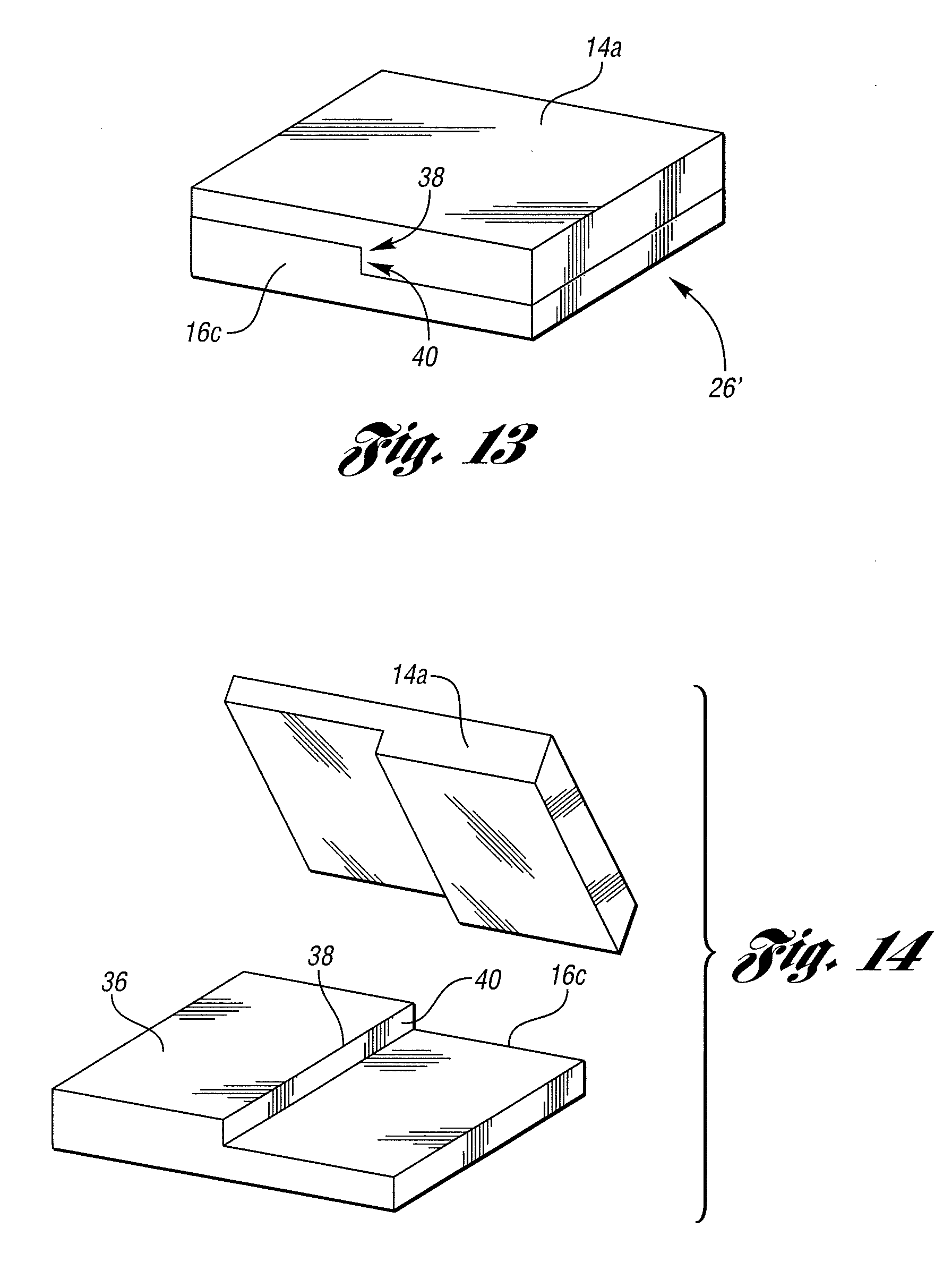
FIG. 13 is a perspective view of exemplary layers of the material layers for use in a giant magnetoresistive (GMR) sensor shown in FIG. 2.
FIG. 14 is an exploded view of the exemplary layers of the material layers for use in a giant magnetoresistive (GMR) sensor shown in FIG. 13.
DETAILED DESCRIPTION
With reference to FIGS. 1-12, a giant magnetoresistive (GMR) sensor having a horizontal stabilizer provided therein and a method for manufacturing such a GMR sensor will be described. For ease of illustration and to facilitate understanding, like reference numerals may be used herein for like components and features throughout the drawings.
As previously noted, GMR sensors used as read elements in magnetic data storage and retrieval systems need to operate in a linear and stable fashion. Such GMR sensors also need to operate as close to equivalent to each other as possible, especially when used as read elements in a multi-track read/write head in magnetic tape data storage and retrieval systems.
GMR sensors, however, are prone to defects which can cause instability and bias point changes during their operation in such data storage and retrieval systems. The GMR sensor disclosed herein minimizes such defects, thereby improving manufacturing yield and allowing the GMR sensor to operate in a more stable fashion in data storage and retrieval systems. The GMR sensor is built incorporating topographic features comprising a step in a layer beneath the working surface of the GMR sensor, such as the tape bearing surface of a GMR sensor in a magnetic tape data storage and retrieval system, where the step is configured parallel to the GMR sensor working surface (i.e., "horizontal"). Such features provide equivalent magnetic fields large enough to minimize the effect of random manufacturing variations, thereby improving yield and providing greater sensor equivalency in multi-track read/write heads.
Referring now to FIG. 1, a perspective view is shown of material layers for use in a prior art anisotropic magnetoresistive (AMR) sensor. As seen therein, an AMR sensor includes a non-magnetoresistive layer (14) and a magnetoresistive layer (16), which together may be referred to as a film stack (18). The non-magnetoresistive layer (14) may comprise Cobalt-Zirconium-Tantalum (CoZrTa), while the magnetoresistive layer (16) may comprise Nickel-Iron (NeFe). As is well known in the art, such an AMR sensor may be manufactured by creating or forming the non-magnetoresistive and magnetoresistive layers (14, 16) using film deposition techniques. As is also well known, one side (20) of the film stack (18) will be formed in a known fashion into a working surface for the AMR sensor, which surface will be oriented proximate a magnetic storage medium (not shown) during operation of the AMR sensor. In a data storage and retrieval system employing magnetic tape as the storage medium, the working surface of the AMR sensor will be the tape bearing surface where the AMR sensor makes contact with the magnetic tape (not shown).
A perspective view of exemplary material layers for use in a GMR sensor is shown in FIG. 2. As seen therein, a GMR sensor comprises a plurality of non-magnetoresistive layers (14a, 14b, 14c) and a plurality of magnetoresistive layers (16a, 16b, 16c, 16d). Here again, as is well known in the art, a GMR sensor may also be manufactured by creating or forming the non-magnetoresistive and magnetoresistive layers (14a-c, 16a-d) using film deposition techniques. In that regard, the film stack (18') of a GMR sensor may comprise a series of adjacent, alternating or interposed non-magnetoresistive layers (14a-c) and magnetoresistive layers (16a-d). As is also well known, one side (20') of the film stack (18') will be formed in a known fashion into a working surface for the GMR sensor, which surface will be oriented proximate a magnetic storage medium (not shown) during operation of the GMR sensor. Here again, in a data storage and retrieval system employing magnetic tape as the storage medium, the working surface of the GMR sensor will be the tape bearing surface where the GMR sensor makes contact with the magnetic tape (not shown).
As seen in FIG. 2, one non-magnetoresistive layer (14a) may comprise Copper (Cu), another non-magnetoresistive layer (14b) may comprise Ruthenium (Ru), and still another non-magnetoresistive layer (14c) may comprise Iridium-Manganese (IrMn). Magnetoresistive layers (16a, 16b) may comprise Nickel-Iron (NiFe) and Cobalt-Iron (CoFe), respectively. Additional magnetoresistive layers (16c, 16d) may comprise Cobalt-Iron (CoFe). It should be noted, however, that the particular magnetoresistive and non-magnetoresistive materials identified herein are exemplary only. Other magnetoresistive and non-magnetoresistive materials may also be employed.
Referring next to FIG. 3, a top view of a prior art AMR sensor (22) is shown, including a stabilizer pattern (24) formed therein. The use of topographical stabilizer techniques and features is well established in the manufacture of AMR sensor read/write heads in order to improve AMR sensor performance when used in magnetic tape data storage and retrieval systems. The salient features of such stabilizers are multiple step height changes beneath the working surface of the sensor.
More specifically, as seen in FIG. 3, a film stack (18) of AMR sensor (22) includes a magnetoresistive layer (16) oriented on top of a non-magnetoresistive layer (14). The film stack (18) will be provided in a known fashion with a working surface (26), which will be oriented proximate a magnetic storage medium (not shown) during operation of the AMR sensor (22). In a data storage and retrieval system where the magnetic storage medium is a magnetic tape, the working surface (26) of the AMR sensor (22) will be the tape bearing surface where the AMR sensor (22) makes contact with a magnetic tape (not shown).
Referring still to FIG. 3, the stabilizer pattern (24) provided in the AMR sensor (22) comprises multiple troughs (28) on the surface of the non-magnetoresistive layer (14) adjacent the magnetoresistive layer (16). As can be seen, the troughs (28) are oriented at a 45.degree. angle relative to a plane formed by the working surface (26) of the AMR sensor (22).
FIG. 4 shows an edge-on view of the prior art AMR sensor (22) depicted in FIG. 3, taken along the line 4-4 thereof. In that regard, FIG. 4 illustrates the stabilizer pattern (24) formed in the AMR sensor (22). As seen therein, multiple troughs (28) provided or formed in the non-magnetoresistive layer (14) create a series of step height changes on surface (30) of the non-magnetoresistive layer (14) adjacent magnetoresistive layer (16). In that regard, it should be noted that the troughs (28) and concomitant surface step height changes may be formed, produced or provided in any known fashion, including chemical processes such as photolithography, or mechanical processes such as machining or ion milling.
Referring next to FIG. 5, a top view is shown of an embodiment of a GMR sensor (30) disclosed herein, including a stabilizer pattern (32) formed therein. With reference again to FIGS. 1 and 2, GMR sensors differ from AMR sensors in that GMR sensors are composed of a stack of multiple film layers, which are relatively thin in comparison to the material layers used in AMR sensors. In view of the relatively thin nature of the layers in a GMR sensor stack, it was thought that any step height changes provided in those layers would damage the film integrity, thereby rendering the GMR sensor substantially inoperable. As a result, it was believed that topographical stabilization features could not be used in GMR sensors.
Recent experiments with GMR sensors, however, have indicated that topographical stabilizers can be quite successfully implemented. Indeed, stabilizers used in GMR sensors may be simpler than those used in AMR sensors in that only a single step, which may progress across the width of the GMR sensor, may be provided. In that regard, as seen in FIGS. 5, 5b and 5c, a portion of a film stack (18') of GMR sensor (30) includes a magnetoresistive layer (16c, 16d) oriented on top of a non-magnetoresistive layer (14a, 14b), or a non-magnetoresistive layer (14c) on top of a magnetoresistive layer (16d). The film stack (18') will be provided in a known fashion with a working surface (26'), which will be oriented proximate a magnetic storage medium (not shown) during operation of the GMR sensor (30). In a data storage and retrieval system where the magnetic storage medium is a magnetic tape, the working surface (26') of the GMR sensor (30) will be the tape bearing surface where the GMR sensor (30) makes contact with a magnetic tape (not shown).
Still referring to FIGS. 5, 5b and 5c, the stabilizer pattern (32) provided in the GMR sensor (30) comprises a single step (34) on the surface of the non-magnetoresistive layer (14a, 14b) adjacent the magnetoresistive layer (16c. 16d), or the non-magnetoresistive layer (14c) adjacent the magnetoresistive layer (16d). As can be seen, the step (34) is oriented substantially parallel to a plane formed by the working surface (26') of the GMR sensor (30). In that regard, as it is oriented substantially parallel to the horizontal plane of the working surface (26'), the step (34) provides a topographical feature that may be referred to as a horizontal stabilizer.
Referring now to FIGS. 6, 6b and 6c, edge-on views of the GMR sensor (30) depicted in FIGS. 5, 5b and 5c are shown, taken along the lines 6-6, 6b-6b and 6c-6c thereof. In that regard, FIGS. 6, 6b and 6c illustrate the stabilizer pattern (32) formed in the GMR sensor (30). As seen therein, the single step (34) provided or formed in the non-magnetoresistive layer (14a, 14b) or the magnetoresistive layer (16d) creates a step height change on surface (36) of the non-magnetoresistive layer (14a, 14b) adjacent magnetoresistive layer (16c, 16d), or the magnetoresistive layer (16d) adjacent non-magnetoresistive layer (14c), thereby forming a transitional surface (40) between first and second levels of the surface (36). The step (34) has an edge (38) that extends in a direction substantially parallel to a plane formed by the working surface (26') (see, FIGS. 5, 5b and 5c) of the GMR sensor (30), which may be a tape bearing surface. Once again, it should be noted that the step (34) and concomitant surface height change may be formed, produced or provided in any known fashion, including through the use of any chemical and/or mechanical process.
With reference to FIGS. 5 and 6, as previously described, the step (34), including the edge (38) thereof, may extend across substantially the entire width of the GMR sensor (30). Moreover, while a step (34) is shown in one non-magnetoresistive layer (14a), a similar step may be provided on a surface of as many as all of the multiple magnetoresistive and non-magnetoresistive layers in sensor stack (18') that make up GMR sensor (30). In that regard, each such step may be substantially coextensive with the step provided in an adjacent layer, so that the steps in each layer are substantially aligned in the sensor stack (18') (see, FIG. 2) and/or extend across substantially the entire width of the GMR sensor (30).
Referring next to FIG. 7, an exemplary flowchart is shown of an embodiment of a method (60) for manufacturing a GMR sensor as disclosed herein. As previously described, the GMR sensor is for reading information from a magnetic storage medium, and has a working surface oriented proximate the magnetic storage medium during operation of the GMR sensor.
As seen in FIG. 7, the method (60) may comprise forming (62) a first non-magnetoresistive layer, forming (64) a first magnetoresistive layer on the first non-magnetoresistive layer, and forming (66) a second non-magnetoresitive layer on the first magnetoresistive layer. The method (60) may further comprise forming (68) a second magnetoresistive layer on the second non-magnetoresistive layer; and forming (70) a third non-magnetoresistive layer on the second magnetoresistive layer. Once again, such magnetoresistive and non-magnetoresistive layers may comprise any of a number of materials, as discussed above in connection with FIGS. 1-6.
Still referring to FIG. 7, the method (60) for manufacturing a GMR sensor may further comprise providing (72) the first non-magnetoresistive layer with a single step on a surface of the first non-magnetoresistive layer, the step having an edge extending in a direction substantially parallel to a plane of the working surface of the GMR sensor. As previously discussed in connection with FIGS. 1-6, the magnetic storage medium may comprise a magnetic tape, the working surface of the GMR sensor may comprise a tape bearing surface, and the edge of the step provided on the surface of the first non-magnetoresistive layer thereby extends in a direction substantially parallel to a plane of the tape bearing surface of the GMR sensor.
The method (60) for manufacturing a GMR sensor may further comprise providing the first magnetoresistive layer with a single step on a surface thereof, where the step provided on the surface of the first magnetoresistive layer is substantially coextensive with the step provided on the surface of the first non-magnetoresistive layer. As previously discussed, the single step provided on the surface of the first non-magnetoresistive layer and the single step provided on the surface of the first magnetoresistive layer may extend across substantially an entire width of the GMR sensor.
The method (60) may still further comprise providing each of the first magnetoresistive layer, the second non-magnetoresistive layer, the second magnetoresistive layer, and the third non-magnetoresistive layer with a single step on a surface thereof, where each step provided on the surface of each layer is substantially coextensive with the step proved on the surface of an adjacent layer. Here again, each of the coextensive steps provided on the surface of each layer may extend across substantially an entire width of the GMR sensor. Moreover, as discussed above in connection with FIGS. 1-6, the single step provided on the surface of any of the magnetoresistive or non-magnetoresistive layers may be produced by a chemical or a mechanical process. It should also be noted that while FIG. 7 shows the steps of the method (60) described herein being executed in a particular order, that order is exemplary only. Such steps may be executed in a different order than that depicted, which may include simultaneous execution of particular steps.
Performance measurements of embodiments of GMR sensors as described herein with horizontal stabilizers in comparison to GMR sensors lacking such features are shown in FIGS. 8-12. Referring first to FIG. 8, a plot depicting amplitude output for multi-sensor GMR heads (80, 82) having horizontal stabilizers as disclosed herein is shown in comparison to a prior art multi-sensor GMR head (84) without stabilization. As seen therein, output on stabilized GMR heads (80, 82) is more tightly controlled than on non-stabilized GMR head (84). While the mean amplitude for stabilized GMR heads (80, 82) has dropped relative to non-stabilized GMR head (84), that lower mean amplitude results from of a lack of high output outliers for stabilized GMR heads (80, 82) as compared to non-stabilized GMR head (84).
Referring next to FIG. 9, a plot depicting asymmetry for multi-sensor GMR heads (80, 82) having horizontal stabilizers as disclosed herein is shown in comparison to a prior art multi-sensor GMR head (84) without stabilization. As seen therein, asymmetry on stabilized GMR heads (80, 82) is more tightly controlled that in non-stabilized GMR head (84). The distribution for stabilized GMR heads (80, 82) is more Gaussian than for non-stabilized GMR head (84), without the large negative asymmetry tail of non-stabilized GMR head (84).
FIG. 10 is a plot depicting stability for multi-sensor GMR heads (80, 82) having horizontal stabilizers as disclosed herein in comparison to a prior art multi-sensor GMR head (84) without stabilization. In that regard, while stability measurements for GMR heads are better displayed as a cumulative distribution function, it is nevertheless easy to distinguish from FIG. 10 that stabilized GMR heads (80, 82) outperform non-stabilized GMR head (84).
Referring now to FIG. 11, a plot depicting Viterbi Quality Metric (VQM) for a multi-sensor GMR head (80) having horizontal stabilizers as disclosed herein is shown in comparison to a prior art multi-sensor GMR head (84) without stabilization. As seen therein, magnetic tape drive test results show that stabilized GMR head (80) has a higher VQM on average than non-stabilized GMR head (84), as well as a much reduced low VQM tail.
FIG. 12 is a plot of block error rate (BLER) for a multi-sensor GMR head having horizontal stabilizers as disclosed herein in comparison to a prior art multi-sensor GMR head without stabilization. As seen therein, magnetic tape drive test results shown that stabilized GMR head (80) has a good block error rate, and does not have the subset of sensors with poorer error rates as does the non-stabilized GMR head (84).
As can be seen from the plots of FIGS. 8-12, multi-sensor GMR heads with horizontal stabilizers improve parametric performance by producing a tighter distribution of amplitude, producing a tighter distribution of asymmetry, and reducing the incidence of unstable sensors to lower levels than multi-sensor GMR heads without stabilization. As well, in terms of drive performance, stabilized GMR heads lead to a higher and better controlled VQM, lower the incidence of higher error rate sensors, and result in lower values of boost in the drive than non-stabilized GMR heads.
Referring now to FIGS. 13 and 14, perspective and exploded views are shown of exemplary layers of the material layers of the stack (18') shown in FIG. 2. As seen therein, and with continuing reference to FIGS. 2, 5 and 6, the stabilizer pattern (32) in the GMR sensor (30) comprises a single step (34) on the surface (36) of the non-magnetoresistive layer (14a) adjacent the magnetoresistive layer (16c). The step (34) is oriented substantially parallel to a plane formed by the working surface (26') of the GMR sensor (30), and therefore provides a topographical feature that may be referred to as a horizontal stabilizer. The single step (34) provided or formed in the non-magnetoresistive layer (14a) creates a step height change on surface (36) of the non-magnetoresistive layer (14a) adjacent magnetoresistive layer (16b). The step (34) has an edge (38) that extends in a direction substantially parallel to a plane formed by the working surface (26') of the GMR sensor (30), which may be a tape bearing surface. The step (34) thus provides a transitional surface (40) in the non-magnetoresistive layer (14a) between first and second levels of the surface (36) of the non-magnetoresistive layer (14a) and has an edge (38) along a line formed by a junction of the transitional surface (40) and the first level of the surface (36) of the non-magnetoresistive layer (14a), where the edge (38) extends in a direction substantially parallel to a plane formed by the working surface (26') of the GMR sensor (30). The step (34), including the edge (38) thereof, may extend across substantially the entire width of the GMR sensor (30). While a step (34) is shown in one non-magnetoresistive layer (14a), a similar step may be provided on a surface of as many as all of the multiple mangetoresistive and non-magnetoresistive layers in the sensor stack (18') that make up GMR sensor (30). Each such step may be substantially coextensive with the step provided in an adjacent layer, so that the steps in each layer are substantially aligned in the sensor stack (18') and/or extend across substantially the entire width of the GMR sensor (30).
As is readily apparent from the foregoing description, a GMR sensor has been disclosed that minimizes defects which can cause instability and bias point changes during sensor operation, thereby improving manufacturing yield and allowing the GMR sensor to operate in a more stable fashion when used in magnetic data storage and retrieval systems. The GMR sensor is built incorporating topographic features comprising a step in a layer beneath the working surface of the GMR sensor, such as the tape bearing surface of a GMR sensor in a magnetic tape data storage and retrieval system, and is configured parallel to that GMR sensor working surface (i.e., "horizontal"). Such features provide equivalent magnetic fields large enough to minimize the effect of random manufacturing variations, thereby providing greater sensor equivalency in multi-track read/write heads. Such a GMR sensor allows multi-track GMR heads to be built with better yield, better performance, and less sensor-to-sensor variation.
While certain embodiments of a GMR sensor having a horizontal stabilizer have been illustrated and described herein, they are exemplary only and it is not intended that these embodiments illustrate and describe all those possible. Rather, the words used herein are words of description rather than limitation, and it is understood that various changes may be made without departing from the spirit and scope of the following claims.
* * * * *
References
D00000
D00001
D00002
D00003
D00004
D00005
D00006
D00007
D00008
XML
uspto.report is an independent third-party trademark research tool that is not affiliated, endorsed, or sponsored by the United States Patent and Trademark Office (USPTO) or any other governmental organization. The information provided by uspto.report is based on publicly available data at the time of writing and is intended for informational purposes only.
While we strive to provide accurate and up-to-date information, we do not guarantee the accuracy, completeness, reliability, or suitability of the information displayed on this site. The use of this site is at your own risk. Any reliance you place on such information is therefore strictly at your own risk.
All official trademark data, including owner information, should be verified by visiting the official USPTO website at www.uspto.gov. This site is not intended to replace professional legal advice and should not be used as a substitute for consulting with a legal professional who is knowledgeable about trademark law.