Electrocautery method and apparatus
Eder , et al.
U.S. patent number 10,314,642 [Application Number 12/410,322] was granted by the patent office on 2019-06-11 for electrocautery method and apparatus. This patent grant is currently assigned to Aesculap AG. The grantee listed for this patent is Peter Seth Edelstein, Joseph Charles Eder, Mark Kane, Camran Nezhat, Benjamin Theodore Nordell, II. Invention is credited to Peter Seth Edelstein, Joseph Charles Eder, Mark Kane, Camran Nezhat, Benjamin Theodore Nordell, II.


| United States Patent | 10,314,642 |
| Eder , et al. | June 11, 2019 |
Electrocautery method and apparatus
Abstract
An electrode structure and a mechanism for automated or user-selected operation or compensation of the electrodes, for example to determine tissue coverage and/or prevent arcing between bottom electrodes during electrocautery is disclosed.
| Inventors: | Eder; Joseph Charles (Los Altos Hills, CA), Nordell, II; Benjamin Theodore (San Mateo, CA), Edelstein; Peter Seth (Menlo Park, CA), Nezhat; Camran (Woodside, CA), Kane; Mark (San Jose, CA) | ||||||||||
|---|---|---|---|---|---|---|---|---|---|---|---|
| Applicant: |
|
||||||||||
| Assignee: | Aesculap AG
(DE) |
||||||||||
| Family ID: | 39708348 | ||||||||||
| Appl. No.: | 12/410,322 | ||||||||||
| Filed: | March 24, 2009 |
Prior Publication Data
| Document Identifier | Publication Date | |
|---|---|---|
| US 20090182323 A1 | Jul 16, 2009 | |
Related U.S. Patent Documents
| Application Number | Filing Date | Patent Number | Issue Date | ||
|---|---|---|---|---|---|
| 12062516 | Apr 4, 2008 | ||||
| 11671891 | Feb 6, 2007 | 8696662 | |||
| 11382635 | May 10, 2006 | 7862565 | |||
| 11371988 | Mar 8, 2006 | 7803156 | |||
| 60725720 | Oct 11, 2005 | ||||
| 60680937 | May 12, 2005 | ||||
| Current U.S. Class: | 1/1 |
| Current CPC Class: | A61B 18/1442 (20130101); A61B 2018/00595 (20130101); A61B 2018/00827 (20130101); A61B 2018/165 (20130101); A61B 2018/00505 (20130101); A61B 2018/00875 (20130101); A61B 2018/0063 (20130101); A61B 2018/00678 (20130101); A61B 2018/00791 (20130101); A61B 2018/00702 (20130101) |
| Current International Class: | A61B 18/14 (20060101); A61B 18/00 (20060101); A61B 18/16 (20060101) |
| Field of Search: | ;606/41,42,49 |
References Cited [Referenced By]
U.S. Patent Documents
| 3356408 | July 1967 | Stutz |
| 3527224 | September 1970 | Rabinowitz |
| 3709215 | January 1973 | Richmond |
| 3742955 | July 1973 | Battista et al. |
| 3845771 | November 1974 | Vise |
| 3920021 | November 1975 | Hittenbrandt |
| 3970088 | July 1976 | Morrison |
| 4018230 | April 1977 | Ochiai et al. |
| 4041952 | August 1977 | Morrison et al. |
| 4072153 | February 1978 | Swartz |
| 4094320 | June 1978 | Newton et al. |
| 4200104 | April 1980 | Harris |
| 4231372 | November 1980 | Newton |
| 4492231 | January 1985 | Auth |
| 4532924 | August 1985 | Auth et al. |
| 4590934 | May 1986 | Malis et al. |
| 4671274 | June 1987 | Sorochenko |
| 4867649 | September 1989 | Kawashima |
| 4972846 | November 1990 | Owens et al. |
| 4976717 | December 1990 | Boyle |
| 4979948 | December 1990 | Geddes et al. |
| 4998527 | March 1991 | Meyers |
| 5037379 | August 1991 | Clayman et al. |
| 5041101 | August 1991 | Seder et al. |
| 5059782 | October 1991 | Fukuyama |
| 5078736 | January 1992 | Behl |
| 5108408 | April 1992 | Lally |
| 5133713 | July 1992 | Huang et al. |
| 5151102 | September 1992 | Kamiyama |
| 5156613 | October 1992 | Sawyer |
| 5178618 | January 1993 | Kanadarpa |
| 5190541 | March 1993 | Abele et al. |
| 5207691 | May 1993 | Nardella |
| 5217030 | June 1993 | Yoon |
| 5234425 | August 1993 | Fogarty et al. |
| 5250074 | October 1993 | Wilk et al. |
| 5267998 | December 1993 | Hagen |
| 5269780 | December 1993 | Roos |
| 5269782 | December 1993 | Sutter |
| 5273524 | December 1993 | Fox et al. |
| 5277201 | January 1994 | Stern |
| 5281216 | January 1994 | Klicek |
| 5282799 | February 1994 | Rydell |
| 5290287 | March 1994 | Boebel et al. |
| 5295990 | March 1994 | Levin |
| 5300068 | April 1994 | Rosar et al. |
| 5300087 | April 1994 | Knoepfler |
| 5312023 | May 1994 | Green et al. |
| 5324289 | June 1994 | Eggers |
| 5330471 | June 1994 | Eggers |
| 5330502 | July 1994 | Hassler et al. |
| 5336237 | August 1994 | Chin et al. |
| 5341807 | August 1994 | Nardella |
| 5342381 | August 1994 | Tidemand |
| 5336229 | September 1994 | Noda |
| 5352223 | October 1994 | McBrayer et al. |
| 5352235 | October 1994 | Koros et al. |
| 5354336 | October 1994 | Kelman et al. |
| 5356408 | October 1994 | Rydell |
| 5374277 | December 1994 | Hassler et al. |
| 5377415 | January 1995 | Gibson |
| 5391166 | February 1995 | Eggers |
| 5395369 | March 1995 | McBrayer et al. |
| 5396900 | March 1995 | Slater et al. |
| 5397320 | March 1995 | Essig et al. |
| 5403312 | April 1995 | Yates et al. |
| 5417687 | May 1995 | Nardella et al. |
| 5423809 | June 1995 | Klicek |
| 5423814 | June 1995 | Zhu et al. |
| 5431676 | July 1995 | Dubrul et al. |
| 5438302 | August 1995 | Goble |
| 5443463 | August 1995 | Stern et al. |
| 5443470 | August 1995 | Stern et al. |
| 5445638 | August 1995 | Rydell et al. |
| 5447513 | September 1995 | Davison et al. |
| 5449355 | September 1995 | Rhum et al. |
| 5456684 | October 1995 | Schmidt et al. |
| 5458598 | October 1995 | Feinberg et al. |
| 5462546 | October 1995 | Rydell |
| 5472442 | December 1995 | Klicek |
| 5480399 | January 1996 | Hebborn |
| 5482054 | January 1996 | Slater et al. |
| 5484435 | January 1996 | Fleenor et al. |
| 5484436 | January 1996 | Eggers et al. |
| 5496312 | March 1996 | Klicek |
| 5496317 | March 1996 | Goble et al. |
| 5514134 | May 1996 | Rydell et al. |
| 5520698 | May 1996 | Koh |
| 5531744 | July 1996 | Nardella et al. |
| 5540684 | July 1996 | Hassler, Jr. |
| 5540685 | July 1996 | Parins et al. |
| 5542945 | August 1996 | Fritzsch |
| 5549606 | August 1996 | McBrayer et al. |
| 5549637 | August 1996 | Crainich |
| 5556397 | September 1996 | Long et al. |
| 5558100 | September 1996 | Cox |
| 5558671 | September 1996 | Yates |
| 5562700 | October 1996 | Huitema et al. |
| 5562701 | October 1996 | Huitema et al. |
| 5562702 | October 1996 | Huitema et al. |
| 5562720 | October 1996 | Stern et al. |
| 5564615 | October 1996 | Bishop et al. |
| 5569243 | October 1996 | Kortenbach |
| 5571100 | November 1996 | Goble et al. |
| 5573535 | November 1996 | Viklund |
| 5578052 | November 1996 | Koros et al. |
| 5601224 | February 1997 | Bishop et al. |
| 5603700 | February 1997 | Daneshvar |
| 5603711 | February 1997 | Parins et al. |
| 5599350 | April 1997 | Schulze et al. |
| 5624452 | April 1997 | Yates |
| 5611803 | May 1997 | Heaven |
| 5637110 | June 1997 | Pennybacker |
| 5637111 | June 1997 | Sutcu et al. |
| 5653692 | August 1997 | Masterson et al. |
| 5658281 | August 1997 | Heard |
| 5662662 | September 1997 | Bishop et al. |
| 5662676 | September 1997 | Koninckx |
| 5665085 | September 1997 | Nardella |
| 5665100 | September 1997 | Yoon |
| 5667526 | September 1997 | Levin |
| 5669907 | September 1997 | Platt et al. |
| 5673840 | October 1997 | Schulze et al. |
| 5673841 | October 1997 | Schulze et al. |
| 5674184 | October 1997 | Hassler, Jr. |
| 5674220 | October 1997 | Fox et al. |
| 5675184 | October 1997 | Matsubayashi et al. |
| 5680982 | October 1997 | Schulze et al. |
| 5681282 | October 1997 | Eggers et al. |
| 5683385 | November 1997 | Kortenbach |
| 5683388 | November 1997 | Slater |
| 5688270 | November 1997 | Yates et al. |
| 5693051 | December 1997 | Schulze et al. |
| 5697949 | December 1997 | Guirtino et al. |
| 5700261 | December 1997 | Brikerhoff |
| 5702390 | December 1997 | Austin et al. |
| 5704534 | January 1998 | Huitema et al. |
| 5707369 | January 1998 | Vaitekunas et al. |
| 5709680 | January 1998 | Yates et al. |
| 5713896 | February 1998 | Nardella et al. |
| 5715832 | February 1998 | Koblish et al. |
| 5718703 | February 1998 | Chin |
| 5720719 | February 1998 | Edwards et al. |
| 5728143 | March 1998 | Gough et al. |
| 5733283 | March 1998 | Malis et al. |
| 5735289 | April 1998 | Pfeffer et al. |
| 5735848 | April 1998 | Yates et al. |
| 5735849 | April 1998 | Baden et al. |
| 5741285 | April 1998 | McBrayer |
| 5743906 | April 1998 | Parins et al. |
| 5746750 | May 1998 | Prestel et al. |
| 5749895 | May 1998 | Sawyer et al. |
| 5755717 | May 1998 | Yates et al. |
| 5769849 | June 1998 | Eggers |
| 5776130 | July 1998 | Buysse et al. |
| 5788662 | August 1998 | Antanavich et al. |
| 5797906 | August 1998 | Rhum et al. |
| 5797941 | August 1998 | Schulze et al. |
| 5810811 | September 1998 | Yates et al. |
| 5817091 | October 1998 | Nardella et al. |
| 5817092 | October 1998 | Behl |
| 5823066 | October 1998 | Huitema et al. |
| 5833689 | November 1998 | Long |
| 5833690 | November 1998 | Yates et al. |
| 5836990 | November 1998 | Li |
| 5840077 | November 1998 | Rowden et al. |
| 5855576 | January 1999 | LeVeen et al. |
| 5860975 | January 1999 | Goble et al. |
| 5891142 | April 1999 | Eggers et al. |
| 5893835 | April 1999 | Witt et al. |
| 5893874 | April 1999 | Bourque et al. |
| 5931835 | August 1999 | Mackey |
| 5931836 | August 1999 | Hatta et al. |
| 5954720 | September 1999 | Wilson et al. |
| 5976128 | November 1999 | Schilling et al. |
| 5979453 | November 1999 | Savage et al. |
| 5983874 | November 1999 | Suzuki |
| 6003517 | December 1999 | Sheffield et al. |
| 6004319 | December 1999 | Goble et al. |
| 6030384 | February 2000 | Nezhat |
| 6039735 | March 2000 | Greep |
| 6050993 | April 2000 | Tu et al. |
| 6050995 | April 2000 | Durgin |
| 6056744 | May 2000 | Edwards |
| 6056746 | May 2000 | Goble et al. |
| 6059766 | May 2000 | Greff |
| 6059782 | May 2000 | Novak et al. |
| 6066139 | May 2000 | Ryan et al. |
| 6068626 | May 2000 | Harrington et al. |
| 6071281 | June 2000 | Burnside et al. |
| 6074386 | June 2000 | Goble et al. |
| 6086586 | July 2000 | Hooven |
| 6090106 | July 2000 | Goble et al. |
| 6093186 | July 2000 | Goble |
| 6096037 | August 2000 | Mulier et al. |
| 6099550 | August 2000 | Yoon |
| 6123701 | September 2000 | Nezhat |
| H1904 | October 2000 | Yates et al. |
| 6142992 | November 2000 | Cheng et al. |
| 6152920 | November 2000 | Thompson et al. |
| 6152932 | November 2000 | Ternstrom |
| 6162220 | December 2000 | Nezhat |
| 6174309 | January 2001 | Wrublewski et al. |
| 6179832 | January 2001 | Jones et al. |
| 6203541 | March 2001 | Kappel |
| 6203542 | March 2001 | Ellsberry et al. |
| 6206877 | March 2001 | Kese et al. |
| 6210406 | April 2001 | Webster |
| 6212426 | April 2001 | Swanson |
| 6217894 | April 2001 | Sawhney et al. |
| 6228084 | May 2001 | Kirwan, Jr. |
| 6234178 | May 2001 | Goble et al. |
| 6241139 | June 2001 | Milliman et al. |
| 6245069 | June 2001 | Gminder |
| 6254601 | July 2001 | Burbank et al. |
| 6258085 | July 2001 | Eggleston |
| 6277114 | August 2001 | Bullivant et al. |
| 6283963 | September 2001 | Regula |
| 6287304 | September 2001 | Eggers et al. |
| 6290715 | September 2001 | Sharkey et al. |
| 6293942 | September 2001 | Goble et al. |
| 6293946 | September 2001 | Thorne |
| 6296636 | October 2001 | Cheng et al. |
| 6306134 | October 2001 | Goble et al. |
| 6312430 | November 2001 | Wilson et al. |
| 6322494 | November 2001 | Bullivant et al. |
| 6327505 | December 2001 | Medhkour et al. |
| 6334861 | January 2002 | Chandler et al. |
| 6350274 | February 2002 | Li |
| 6361559 | March 2002 | Hauser et al. |
| 6364879 | April 2002 | Chen et al. |
| 6371956 | April 2002 | Wilson et al. |
| 6391024 | May 2002 | Sun et al. |
| 6391029 | May 2002 | Hooven et al. |
| 6398779 | June 2002 | Buysse et al. |
| 6398781 | June 2002 | Goble et al. |
| H2037 | July 2002 | Yates et al. |
| 6416509 | July 2002 | Goble et al. |
| 6423057 | July 2002 | He et al. |
| 6428550 | August 2002 | Vargas et al. |
| 6436096 | August 2002 | Hareyama |
| 6440130 | August 2002 | Mulier et al. |
| 6443952 | September 2002 | Mulier et al. |
| 6464702 | October 2002 | Schulze et al. |
| 6485486 | November 2002 | Trembly et al. |
| 6485489 | November 2002 | Teirstein et al. |
| 6491690 | December 2002 | Goble et al. |
| 6494881 | December 2002 | Bales et al. |
| 6500176 | December 2002 | Truckai et al. |
| 6514252 | February 2003 | Nezhat et al. |
| 6517530 | February 2003 | Kleven |
| 6520185 | February 2003 | Bommannan et al. |
| 6533784 | March 2003 | Truckai et al. |
| 6546933 | April 2003 | Yoon |
| 6554829 | April 2003 | Schulze et al. |
| 6564806 | May 2003 | Fogarty et al. |
| 6565560 | May 2003 | Goble et al. |
| 6565561 | May 2003 | Goble et al. |
| 6584360 | June 2003 | Francischelli |
| 6610060 | August 2003 | Mulier et al. |
| 6610074 | August 2003 | Santilli |
| 6613048 | September 2003 | Mulier et al. |
| 6616654 | September 2003 | Mollenauer |
| 6616659 | September 2003 | de la Torre et al. |
| 6619529 | September 2003 | Green et al. |
| 6623482 | September 2003 | Pendekanti et al. |
| 6626901 | September 2003 | Treat et al. |
| 6645198 | November 2003 | Bommannan et al. |
| 6645201 | November 2003 | Utley et al. |
| 6648839 | November 2003 | Manna |
| 6652518 | November 2003 | Wellman |
| 6656177 | December 2003 | Truckai et al. |
| 6666859 | December 2003 | Fleenor et al. |
| 6673085 | January 2004 | Berg |
| 6676660 | January 2004 | Wampler et al. |
| 6682526 | January 2004 | Jones et al. |
| 6682527 | January 2004 | Strul |
| 6695840 | February 2004 | Schulze |
| 6699245 | March 2004 | Dinger et al. |
| 6719754 | April 2004 | Underwood et al. |
| 6722371 | April 2004 | Fogarty et al. |
| 6726682 | April 2004 | Harrington et al. |
| 6736814 | May 2004 | Manna et al. |
| 6743229 | June 2004 | Buysse et al. |
| 6746488 | June 2004 | Bales |
| 6752154 | June 2004 | Fogarty et al. |
| 6752803 | June 2004 | Goldman et al. |
| 6755827 | June 2004 | Mulier et al. |
| 6770070 | August 2004 | Balbierz |
| 6770072 | August 2004 | Truckai et al. |
| 6773435 | August 2004 | Schulze et al. |
| 6776780 | August 2004 | Mulier et al. |
| 6796981 | September 2004 | Wham |
| 6808525 | October 2004 | Latterell et al. |
| 6817974 | November 2004 | Cooper et al. |
| 6821273 | November 2004 | Mollenauer |
| 6837888 | January 2005 | Ciarrocca et al. |
| 6840938 | January 2005 | Morley et al. |
| 6843789 | January 2005 | Goble |
| 6852108 | February 2005 | Barry et al. |
| 6858028 | February 2005 | Mulier et al. |
| 6889089 | May 2005 | Behl et al. |
| 6893435 | May 2005 | Goble |
| 6896672 | May 2005 | Eggers et al. |
| 6896673 | May 2005 | Hooven |
| 6902536 | June 2005 | Manna et al. |
| 6905506 | June 2005 | Burbank |
| 6908463 | June 2005 | Treat et al. |
| 6913579 | July 2005 | Truckai et al. |
| 6918907 | July 2005 | Kelly et al. |
| 6918909 | July 2005 | Ohyama et al. |
| 6923803 | August 2005 | Goble |
| 6923806 | August 2005 | Hooven et al. |
| 6926712 | August 2005 | Phan |
| 6929642 | August 2005 | Xiao et al. |
| 6936048 | August 2005 | Hurst |
| 6939346 | September 2005 | Kannenberg et al. |
| 6953461 | October 2005 | McClurken et al. |
| 6981628 | January 2006 | Wales |
| 7008421 | March 2006 | Daniel et al. |
| 7033356 | April 2006 | Latterell |
| 7063699 | June 2006 | Hess et al. |
| 7090637 | August 2006 | Danitz et al. |
| 7090673 | August 2006 | Dycus et al. |
| 7090685 | August 2006 | Kortenbach et al. |
| 7094235 | August 2006 | Francischelli |
| 7101371 | September 2006 | Dycus et al. |
| 7101372 | September 2006 | Dycus et al. |
| 7101373 | September 2006 | Dycus et al. |
| 7118587 | October 2006 | Dycus et al. |
| 7125409 | October 2006 | Truckai et al. |
| 7137980 | November 2006 | Buysse et al. |
| 7159750 | January 2007 | Racenet et al. |
| 7166102 | January 2007 | Fleenor et al. |
| 7169146 | January 2007 | Truckai et al. |
| 7179254 | February 2007 | Pendekanti et al. |
| 7195627 | March 2007 | Amoah et al. |
| 7220260 | May 2007 | Fleming et al. |
| 7238195 | July 2007 | Viola |
| 7250048 | July 2007 | Francischelli et al. |
| 7255697 | August 2007 | Dycus et al. |
| 7267677 | September 2007 | Johnson et al. |
| 7270664 | September 2007 | Johnson et al. |
| 7276068 | October 2007 | Johnson et al. |
| 7278991 | October 2007 | Morris et al. |
| 7291143 | November 2007 | Swanson |
| 7303557 | December 2007 | Wham |
| 7329256 | February 2008 | Johnson et al. |
| 7364577 | April 2008 | Wham et al. |
| 7367972 | May 2008 | Francischelli et al. |
| 7410483 | August 2008 | Danitz et al. |
| 7494039 | February 2009 | Racenet et al. |
| 7506790 | March 2009 | Shelton, IV et al. |
| 7513898 | April 2009 | Johnson et al. |
| 7540872 | June 2009 | Schechter et al. |
| 7549564 | June 2009 | Boudreaux |
| 7588566 | September 2009 | Treat et al. |
| 7624902 | December 2009 | Marczyk |
| 7641651 | January 2010 | Nezhat et al. |
| 7651492 | January 2010 | Wham |
| 7703653 | April 2010 | Shah |
| 7794461 | September 2010 | Eder et al. |
| 7803156 | September 2010 | Eder et al. |
| 7862565 | January 2011 | Eder et al. |
| 8147485 | April 2012 | Wham |
| 8696662 | April 2014 | Eder |
| 2001/0029367 | October 2001 | Fleenor et al. |
| 2002/0062123 | May 2002 | McClurken et al. |
| 2002/0062136 | May 2002 | Hillstead et al. |
| 2002/0107514 | August 2002 | Hooven |
| 2002/0124853 | September 2002 | Burbank et al. |
| 2002/0128643 | September 2002 | Simpson et al. |
| 2002/0151882 | October 2002 | Marko et al. |
| 2002/0177848 | November 2002 | Truckai et al. |
| 2002/0183734 | December 2002 | Bommannan |
| 2002/0183738 | December 2002 | Chee et al. |
| 2003/0004510 | January 2003 | Wham et al. |
| 2003/0015855 | January 2003 | McCoy |
| 2003/0018331 | January 2003 | Dycus et al. |
| 2003/0078577 | April 2003 | Truckai et al. |
| 2003/0114849 | June 2003 | Ryan |
| 2003/0144652 | July 2003 | Baker et al. |
| 2003/0144653 | July 2003 | Francischelli et al. |
| 2003/0153908 | August 2003 | Goble et al. |
| 2003/0158547 | August 2003 | Phan |
| 2003/0158551 | August 2003 | Paton et al. |
| 2003/0171745 | September 2003 | Francischelli et al. |
| 2003/0199863 | October 2003 | Swanson |
| 2003/0199869 | October 2003 | Johnson et al. |
| 2003/0216726 | November 2003 | Eggers et al. |
| 2003/0229344 | December 2003 | Dycus et al. |
| 2003/0236549 | December 2003 | Bonadio et al. |
| 2004/0006339 | January 2004 | Underwood et al. |
| 2004/0010245 | January 2004 | Cerier et al. |
| 2004/0049185 | March 2004 | Latterell et al. |
| 2004/0068274 | April 2004 | Hooven |
| 2004/0097919 | May 2004 | Wellman et al. |
| 2004/0106917 | June 2004 | Ormsby et al. |
| 2004/0122423 | June 2004 | Dycus et al. |
| 2004/0143263 | July 2004 | Schechter et al. |
| 2004/0167508 | August 2004 | Wham |
| 2004/0193148 | September 2004 | Wham et al. |
| 2004/0199226 | October 2004 | Shadduck |
| 2004/0236320 | November 2004 | Protensko et al. |
| 2004/0236326 | November 2004 | Schulze et al. |
| 2005/0010212 | January 2005 | McClurken et al. |
| 2005/0015085 | January 2005 | McClurken et al. |
| 2005/0019654 | January 2005 | Kishida |
| 2005/0021024 | January 2005 | Hooven |
| 2005/0021026 | January 2005 | Baily |
| 2005/0021027 | January 2005 | Shields et al. |
| 2005/0033276 | February 2005 | Adachi |
| 2005/0033277 | February 2005 | Clague et al. |
| 2005/0033278 | February 2005 | McClurken et al. |
| 2005/0033282 | February 2005 | Hooven |
| 2005/0070895 | March 2005 | Ryan et al. |
| 2005/0070978 | March 2005 | Bek et al. |
| 2005/0090819 | April 2005 | Goble |
| 2005/0096645 | May 2005 | Wellman et al. |
| 2005/0096694 | May 2005 | Lee |
| 2005/0101951 | May 2005 | Wham |
| 2005/0107781 | May 2005 | Ostrovsky et al. |
| 2005/0107784 | May 2005 | Moses et al. |
| 2005/0113817 | May 2005 | Isaacson et al. |
| 2005/0113820 | May 2005 | Goble et al. |
| 2005/0113826 | May 2005 | Johnson et al. |
| 2005/0119654 | June 2005 | Swanson et al. |
| 2005/0131390 | June 2005 | Heinrich et al. |
| 2005/0137591 | June 2005 | Barry et al. |
| 2005/0149073 | July 2005 | Arani et al. |
| 2005/0171530 | August 2005 | Hooven |
| 2005/0171533 | August 2005 | Latterell et al. |
| 2005/0187561 | August 2005 | Lee-Sepsick et al. |
| 2005/0192568 | September 2005 | Truckai et al. |
| 2005/0192633 | September 2005 | Montpetit |
| 2005/0196421 | September 2005 | Hunter |
| 2005/0203500 | September 2005 | Saadat et al. |
| 2005/0203504 | September 2005 | Wham et al. |
| 2005/0209664 | September 2005 | Hunter |
| 2005/0226682 | October 2005 | Chersky et al. |
| 2005/0256522 | November 2005 | Franciscelli et al. |
| 2005/0256524 | November 2005 | Long et al. |
| 2005/0261676 | November 2005 | Hall et al. |
| 2006/0025765 | February 2006 | Landman et al. |
| 2006/0025812 | February 2006 | Shelton |
| 2006/0041254 | February 2006 | Francischelli et al. |
| 2006/0052778 | March 2006 | Chapman et al. |
| 2006/0052779 | March 2006 | Hammill |
| 2006/0064084 | March 2006 | Haemmerich |
| 2006/0064085 | March 2006 | Schechter et al. |
| 2006/0064086 | March 2006 | Odom |
| 2006/0079872 | April 2006 | Eggleston |
| 2006/0142751 | June 2006 | Treat et al. |
| 2006/0167451 | July 2006 | Cropper |
| 2006/0189980 | August 2006 | Johnson et al. |
| 2006/0190029 | August 2006 | Wales |
| 2006/0199999 | September 2006 | Ikeda et al. |
| 2006/0217709 | September 2006 | Couture et al. |
| 2006/0226196 | October 2006 | Hueil et al. |
| 2006/0229665 | October 2006 | Wales et al. |
| 2006/0253117 | November 2006 | Hovda et al. |
| 2006/0258954 | November 2006 | Timberlake et al. |
| 2006/0259034 | November 2006 | Eder et al. |
| 2006/0259035 | November 2006 | Nezhat |
| 2006/0271037 | November 2006 | Maroney et al. |
| 2006/0271038 | November 2006 | Johnson et al. |
| 2006/0271041 | November 2006 | Eder |
| 2006/0271042 | November 2006 | Latterell et al. |
| 2006/0287674 | December 2006 | Ginn et al. |
| 2006/0289602 | December 2006 | Wales et al. |
| 2006/0293649 | December 2006 | Lorang |
| 2006/0293655 | December 2006 | Sartor |
| 2007/0005053 | January 2007 | Dando |
| 2007/0005061 | January 2007 | Eder et al. |
| 2007/0055231 | March 2007 | Dycus et al. |
| 2007/0062017 | March 2007 | Dycus et al. |
| 2007/0073340 | March 2007 | Shelton, IV |
| 2007/0128174 | June 2007 | Kleinsek et al. |
| 2007/0129726 | June 2007 | Eder et al. |
| 2007/0173803 | July 2007 | Wham et al. |
| 2007/0173804 | July 2007 | Wham et al. |
| 2007/0173805 | July 2007 | Weinberg et al. |
| 2007/0173811 | July 2007 | Couture et al. |
| 2007/0179497 | August 2007 | Eggers et al. |
| 2007/0185482 | August 2007 | Eder et al. |
| 2007/0208330 | September 2007 | Treat et al. |
| 2007/0244538 | October 2007 | Eder et al. |
| 2007/0250113 | October 2007 | Hegeman et al. |
| 2007/0260242 | November 2007 | Dycus et al. |
| 2007/0265613 | November 2007 | Edelstein et al. |
| 2007/0282318 | December 2007 | Spooner et al. |
| 2007/0282320 | December 2007 | Buysse et al. |
| 2007/0299439 | December 2007 | Latterell et al. |
| 2008/0015562 | January 2008 | Hong |
| 2008/0039835 | February 2008 | Johnson et al. |
| 2008/0045947 | February 2008 | Johnson et al. |
| 2008/0114351 | May 2008 | Irisawa et al. |
| 2008/0114356 | May 2008 | Johnson et al. |
| 2008/0172052 | July 2008 | Eder et al. |
| 2008/0188844 | August 2008 | McGreevy et al. |
| 2008/0195093 | August 2008 | Couture et al. |
| 2008/0221565 | September 2008 | Eder et al. |
| 2008/0228179 | September 2008 | Eder et al. |
| 2008/0275446 | November 2008 | Messerly |
| 2008/0308607 | December 2008 | Timm |
| 2009/0018535 | January 2009 | Schechter et al. |
| 2009/0138006 | May 2009 | Bales et al. |
| 2009/0149853 | June 2009 | Shields et al. |
| 2009/0157071 | June 2009 | Wham et al. |
| 2009/0157072 | June 2009 | Wham et al. |
| 2009/0157075 | June 2009 | Wham et al. |
| 2009/0171354 | July 2009 | Deville et al. |
| 2009/0182323 | July 2009 | Eder |
| 2009/0198272 | August 2009 | Kerver et al. |
| 2009/0209953 | August 2009 | Schoenman |
| 2009/0234347 | September 2009 | Treat et al. |
| 2009/0240245 | September 2009 | Deville et al. |
| 2009/0299367 | December 2009 | Ginnebaugh et al. |
| 2010/0042093 | February 2010 | Wham et al. |
| 2010/0076427 | March 2010 | Heard |
| 2010/0094282 | April 2010 | Kabaya |
| 2010/0280508 | November 2010 | Eder |
| 2010/0298823 | November 2010 | Cao et al. |
| 2011/0202058 | August 2011 | Eder |
| 2061215 | Feb 1992 | CA | |||
| 1250360 | Apr 2000 | CN | |||
| 1882289 | Dec 2006 | CN | |||
| 487269 | May 1991 | EP | |||
| 440385 | Jul 1991 | EP | |||
| 502268 | Sep 1992 | EP | |||
| 562195 | Sep 1993 | EP | |||
| 658333 | Jun 1995 | EP | |||
| 536998 | Apr 1996 | EP | |||
| 518230 | May 1996 | EP | |||
| 0737446 | Oct 1996 | EP | |||
| 875209 | Apr 1998 | EP | |||
| 878169 | Nov 1998 | EP | |||
| 640315 | Dec 1998 | EP | |||
| 923907 | Jun 1999 | EP | |||
| 640317 | Sep 1999 | EP | |||
| 771176 | Jul 2000 | EP | |||
| 1050278 | Nov 2000 | EP | |||
| 1064886 | Jan 2001 | EP | |||
| 833593 | Feb 2001 | EP | |||
| 1254637 | Nov 2002 | EP | |||
| 0717960 | Feb 2003 | EP | |||
| 1293169 | Mar 2003 | EP | |||
| 1293170 | Mar 2003 | EP | |||
| 869742 | May 2003 | EP | |||
| 1330989 | Jul 2003 | EP | |||
| 1330991 | Jul 2003 | EP | |||
| 1344498 | Sep 2003 | EP | |||
| 873089 | Oct 2003 | EP | |||
| 742696 | Nov 2003 | EP | |||
| 1041933 | Mar 2004 | EP | |||
| 959784 | Apr 2004 | EP | |||
| 0794735 | Jul 2004 | EP | |||
| 1004277 | Jul 2004 | EP | |||
| 959786 | Sep 2004 | EP | |||
| 913126 | Oct 2004 | EP | |||
| 956827 | Oct 2004 | EP | |||
| 1472984 | Nov 2004 | EP | |||
| 1025807 | Dec 2004 | EP | |||
| 1486177 | Dec 2004 | EP | |||
| 1518498 | Mar 2005 | EP | |||
| 1518499 | Mar 2005 | EP | |||
| 927543 | Apr 2005 | EP | |||
| 1532933 | May 2005 | EP | |||
| 1586281 | Oct 2005 | EP | |||
| 1621146 | Feb 2006 | EP | |||
| 1632192 | Mar 2006 | EP | |||
| 1637086 | Mar 2006 | EP | |||
| 1645234 | Apr 2006 | EP | |||
| 1645237 | Apr 2006 | EP | |||
| 1747761 | Jan 2007 | EP | |||
| 1767164 | Mar 2007 | EP | |||
| 1852081 | Nov 2007 | EP | |||
| 1862138 | Dec 2007 | EP | |||
| 1039862 | May 2008 | EP | |||
| 1707143 | Jun 2008 | EP | |||
| 1958583 | Aug 2008 | EP | |||
| 2065006 | Jun 2009 | EP | |||
| 2106764 | Oct 2009 | EP | |||
| 2110093 | Oct 2009 | EP | |||
| 09-501328 | Feb 1997 | JP | |||
| A 11070123 | Mar 1999 | JP | |||
| A 11070124 | Mar 1999 | JP | |||
| 2001-518344 | Oct 2001 | JP | |||
| A 2003/088534 | Mar 2003 | JP | |||
| A 2004/049566 | Feb 2004 | JP | |||
| A 2005/021703 | Jan 2005 | JP | |||
| 2005040616 | Feb 2005 | JP | |||
| 2005-512671 | May 2005 | JP | |||
| 2005517498 | Jun 2005 | JP | |||
| A 2005/144193 | Jun 2005 | JP | |||
| 2007195973 | Aug 2007 | JP | |||
| 2008114042 | May 2008 | JP | |||
| WO 92/22257 | Dec 1992 | WO | |||
| WO 93/08754 | May 1993 | WO | |||
| WO 94/00060 | Jan 1994 | WO | |||
| WO94/26179 | Nov 1994 | WO | |||
| WO 94/26228 | Nov 1994 | WO | |||
| WO 95/02371 | Jan 1995 | WO | |||
| WO 95/09576 | Apr 1995 | WO | |||
| WO 95/14436 | Jun 1995 | WO | |||
| WO 95/25471 | Sep 1995 | WO | |||
| WO 96/05776 | Feb 1996 | WO | |||
| WO-9619152 | Jun 1996 | WO | |||
| WO1996016605 | Jun 1996 | WO | |||
| WO 96/23449 | Aug 1996 | WO | |||
| WO 97/24073 | Jul 1997 | WO | |||
| WO 97/24074 | Jul 1997 | WO | |||
| WO 97/24995 | Jul 1997 | WO | |||
| WO 98/12999 | Apr 1998 | WO | |||
| WO 98/43548 | Oct 1998 | WO | |||
| WO 98/53750 | Dec 1998 | WO | |||
| WO99/17670 | Apr 1999 | WO | |||
| WO 99/17670 | Apr 1999 | WO | |||
| WO 99/23933 | May 1999 | WO | |||
| WO 99/51155 | Oct 1999 | WO | |||
| WO 99/51158 | Oct 1999 | WO | |||
| WO 99/52459 | Oct 1999 | WO | |||
| WO 99/56646 | Nov 1999 | WO | |||
| WO 00/13192 | Mar 2000 | WO | |||
| WO 00/13193 | Mar 2000 | WO | |||
| WO 00/47124 | Aug 2000 | WO | |||
| WO-0051512 | Sep 2000 | WO | |||
| WO2001012090 | Feb 2001 | WO | |||
| WO 01/35846 | May 2001 | WO | |||
| WO 01/54602 | Aug 2001 | WO | |||
| WO 01/58372 | Aug 2001 | WO | |||
| WO01/58373 | Aug 2001 | WO | |||
| WO 01/82812 | Nov 2001 | WO | |||
| WO 02/24092 | Mar 2002 | WO | |||
| WO 02/36028 | May 2002 | WO | |||
| WO 02/67798 | Jul 2002 | WO | |||
| WO 02/58542 | Aug 2002 | WO | |||
| WO 02/071926 | Sep 2002 | WO | |||
| WO 03/024348 | Mar 2003 | WO | |||
| WO 03/053266 | Jul 2003 | WO | |||
| WO03/053266 | Jul 2003 | WO | |||
| WO03/088806 | Oct 2003 | WO | |||
| WO 03/96886 | Nov 2003 | WO | |||
| WO 03/103522 | Dec 2003 | WO | |||
| WO2004/032776 | Apr 2004 | WO | |||
| WO2004032596 | Apr 2004 | WO | |||
| WO2004073490 | Sep 2004 | WO | |||
| WO 04/98383 | Nov 2004 | WO | |||
| WO 04/103156 | Dec 2004 | WO | |||
| WO 05/09213 | Feb 2005 | WO | |||
| WO 05/34729 | Apr 2005 | WO | |||
| WO 2005/030071 | Apr 2005 | WO | |||
| WO 05/79901 | Sep 2005 | WO | |||
| WO 05/115251 | Dec 2005 | WO | |||
| WO2006/060431 | Jun 2006 | WO | |||
| WO 06/124601 | Nov 2006 | WO | |||
| WO2006124518 | Nov 2006 | WO | |||
| WO2007/002227 | Jan 2007 | WO | |||
| WO2007/082061 | Jul 2007 | WO | |||
| WO2008/094554 | Aug 2008 | WO | |||
| WO2008094564 | Aug 2008 | WO | |||
| 2008124112 | Oct 2008 | WO | |||
| WO2009070780 | Jun 2009 | WO | |||
| WO2009154976 | Dec 2009 | WO | |||
Other References
|
Australian Examination Report for Application No. 2008214068, dated Jan. 28, 2011. cited by applicant . Australian Examination Report for Application No. 2008275543, dated Nov. 9, 2010. cited by applicant . Canadian Examination Report for Application No. 2,677,300, dated Aug. 25, 2011. cited by applicant . Canadian Examination Report for Application No. 2,677,444, dated Aug. 18, 2011. cited by applicant . Japanese Examination Report for Application No. 2009-549182, dated Oct. 27, 2011 with English translation. cited by applicant . Japanese Examination Report for Application No. 2009-549183, dated Oct. 27, 2011 with English translation. cited by applicant . European Patent Office Examination Report for Application No. EP 07 758 098.3 dated Feb. 8, 2012. cited by applicant . European Application Serial No. 08826108.6, Extended European Search Report dated Mar. 30, 2012, 7 pgs. cited by applicant . Kerver et al.; U.S. Appl. No. 13/070,391 entitled "Articulable electrosurgical instrument with a stabilizable articulation actuator," filed Mar. 23, 2011. cited by applicant . Van Lue et al.; U.S. Appl. No. 13/110,848 entitled "Electrosurgical tissue sealing augmented with a seal-enhancing composition," filed May 18, 2011. cited by applicant . Examination Report for Canadian Application No. 2,677,300 dated Mar. 28, 2012. cited by applicant . Abu-Rustum, NR, et al.; Transperitoneal Laparoscopic Pelvic and Para-Aortic Lymph Node Dissection Using the Argon-Beam Coagulator and Monopolar Instruments: An 8-Year Study and Description of Technique; Gynecol Oncol. Jun. 2003; 89 (3): 504-13; Memorial Sloan-Kettering Cancer Center, 1275 York Avenue, New York, NY 10021, USA. gynbreast@mskcc.org. cited by applicant . Aoki, T. et al.; Thoracoscopic Resection of the Lung With the Ultrasonic Scalpel; Ann Thorac Surg. Apr. 1999; 67 (4): 1181-3; Department of Thoracic Surgery, Saiseikai Kanagawaken Hospital, Yokohama, Japan. cited by applicant . Arthrocare Receives Clearance to Market Coblation-Based Devices for Gynecology and Laparoscopic Surgery; Clearance Includes Plasma Forceps and 21 Specific Indications; Business Wire, p. 0524; Oct. 25, 2001. cited by applicant . Bergamaschi, R. et al.; Laparoscopic Intracorporeal Bowel Resection With Ultrasound Versus Electrosurgical Dissection; JSLS. Jan.-Mar. 2001; 5 (1): 17-20; National Center for Advanced Laparoscopic Surgery, Tondheim, Norway. r.bergamaschi@altavista.net. cited by applicant . Berguer, Ramon et al.; "SAGES 2001 Hands-On Course I--Taking It to the Next Level: Advanced Laparoscopic Techniques"; Apr. 18, 2001; http://www.sages.org/01program/syllabi/ho1/ho1.html#schirmer. cited by applicant . Briani, S. et al.; Pseudo-Bipolar Electrocoagulation With a Branched Forceps; Minerva Neurochir. 1967; 11 (3): 306-11. cited by applicant . Cakan, A. et al.; The Histological Effect of Harmonic Scalpel and Electrocautery in Lung Resectioris. An Experimental Study in a Rat Model; J Cardiovasc Surg (Torino). Feb. 2004; 45 (1): 63-5; Department of Thoracic Surgery, Ege University School of Medicine, Izmir, Turkey. alpcakan@gohip.com. cited by applicant . Ceviker, N. et al.; A New Coated Bipolar Coagulator: Technical Note; Acta Neurochir (Wien). 1998; 140 (6): 619-20; Department of Neurosurgery, Faculty of Medicine, Gazi University, Ankara, Turkey. cited by applicant . Cherchi, PL, et al.; Utility of Bipolar Electrocautery Scissors for Cervical Conization; Eur J Gynaecol Oncol. 2002; 23 (2): 154-6; Department of Pharmacology, Gynecology and Obstetrics, University of Sassari, Italy. cited by applicant . Circon Corporation--Company Report; Investext, p. 1-13; Jan. 3, 1995. cited by applicant . Colvin, D.P. et al.; Development of an Endoscopic RF Hyperthermia System for Deep Tumor Therapy; American Society of Mechanical Engineers, Heat Transfer Division, (Publication) HTD v. 95. Publ by ASME (BED-v 7), New York, NY, USA p. 25-30; 1987. cited by applicant . Corson, S.L.; Two New Laparoscopic Instruments: Bipolar Sterilizing Forceps and Uterine Manipulator; Medical Instrumentation vol. 11, No. 1 p. 7-8; Jan.-Feb. 1977; USA. cited by applicant . Curon Announces the Publication of Data Supporting Durability and Effectiveness of Stretta (R) System;--Positive One Year Follow-Up Data of U.S. Clinical Trial Published in Gastrointestinal Endoscopy; PR Newswire, pNYTH10307022002; Feb. 7, 2002. cited by applicant . Curon Medical Announces Presentation of Positive Clinical Study Results of Stretta(R) Procedure for Gastroesophageal Reflux Disease (GERD); PR Newswire, pNYW07920032002; Mar. 20, 2002. cited by applicant . Daniel, P. et al.; Ultrasonic Sealing of the Lung Parenchyma After Atypical Resection; Z Exp Chir Transplant Kunstliche Organe. 1987; 20 (2): 117-21. cited by applicant . Digeronimo, EM et al.; Cut-Blot-Coaqulate: A New Time Saving Device; Plast Reconstr Surg. Nov. 1982; 70 (5): 639-40. cited by applicant . Dubuc-Lissoir, J.; Use of a New Energy-Based Vessel Ligation Device During Laparoscopic Gynecologic Oncologic Surgery; Surg Endosc. Mar. 2002; 17 (3): 466-8. Epub Oct. 31, 2002; Department of Obstetrics and Gynecology, CHUM--Notre-Dame Hospital, Pavillon Charles-Simard, 2065 Alexandre-de-Seve, 4th Floor, Montreal, Quebec, Canada, H2L 2W5. josee.dubuc-lissoir.chum@ssss.gouv.dc.ca. cited by applicant . Eichfeld U., et al.; Evaluation of Ultracision in Lung Metastatic Surgery; Ann Thorac Surg. Oct. 2000; 70 (4): 1181-4; Department of Surgery I, General Surgery, Surgical Oncology and Thoracic Surgery, and Institute of Pathology, University of Leipzig, Germany. eichu@medizin.uni-leipzig.de. cited by applicant . Enable Medical Introduces Second Generation Bipolar Scissors; Health Industry Today, pNA; Dec. 1998. cited by applicant . Ercoli, A. et al.; Radiofrequency Bipolar Coagulation for Radical Hysterectomy: Technique, Feasibility and Complications; Int J Gynecol Cancer. Mar.-Apr. 2003; 13 (2): 187-91;Department of Obstetrics and Gynecology, Catholic University, Rome, Italy. cited by applicant . Everest Medical Announces Introduction of 3mm Bipolar Forceps; PR Newswire, p1002MNW021; Oct. 2, 1996. cited by applicant . Everest Medical Discusses Patent Status; Forecasts $1 Million Revenue First Quarter; Introduces Next Generation Bipolar Scissors; PR Newswire, p. N/A; Mar. 31, 1994. cited by applicant . Everest Medical Introduces New Quadripolar (TM) Cutting Forceps at the Global Congress of Gynecologic Endoscopy Meeting; PR Newswire p8927; Nov. 8, 1999. cited by applicant . Everest Medical Releases Bicoag (TM) for Use in Treating Bleeding Ulcers; News Release, p. 1; May 9, 1990. cited by applicant . Everest Medical Reports Record First Quarter Results; Introduces Next Generation Bipolar Scissors; PR Newswire, p. N/A; Apr. 19, 1994. cited by applicant . Forestier D. et al.; Do Bipolar Scissors Increase Postoperative Adhesions? An Experimental Double-Blind Randomized Trial; Ann Chir. Nov. 2002; 127 (9): 680-4; Service de chirurgie generale et digestive, Hotel-Dieu, boulevard Leon-Malfreyt, 63058 Clermont-Ferrand, France. cited by applicant . Gerasin VA et al.; Endoscopic Electrosurgery of the Trachea and Bronchi; Grudn Khir. Sep.-Oct. 1988; (5): 50-3. cited by applicant . Gyrus Medical: LP Scissors; retrieved on Oct. 20, 2004 from website: http://www.gyrusgroup.com/medical/products_item.asp?id=11. cited by applicant . Gyrus Medical: Micro/Macro-Jaw Forceps; retrieved on Oct. 20, 2005 from website: http://www.gyrusgroup.com/medical/products_item.asp?id=13. cited by applicant . Gyr, T. et al.; Minimal Invasive Laparoscopic Hysterectomy With Ultrasonic Scalpel; Am J Surg. Jun. 2001; 181 (6): 516-9; Department of Obstetrics and Gynecology, Regional Hospital, Lugano, Switzerland. cited by applicant . Gyrus Medical: Cutting Forceps; retrieved on Oct. 20, 2005 from website: http://www.gyrusgroup.com/medical/products_item.asp?id=7 cited by applicant . Gyrus Medical: Lyons TM Dissecting Forceps; retrieved on Oct. 20, 2005 from website: http://www.gyrusgroup.com/rnedical/products_item.asp?id=8. cited by applicant . Gyrus Medical: Seal TM Open Forceps; retrieved on Oct. 20, 2005 from website: http://www.gyrusgroup.com/medical/products_item.asp?id=15. cited by applicant . Harrell, AG et al.; Energy Sources in Laparoscopy; Semin Laparosc Surg. Sep. 2004; 11 (3): 201-9; Carolinas Laparoscopic and Advanced Surgery Program, Carolinas Medical Center, Charlotte, NC 28203, USA. cited by applicant . Hayashi A. et al.; Experimental and Clinical Evaluation of the Harmonic Scalpel in Thoracic Surgery; Kurume Med J. 1999; 46 (1): 25-9; Department of Surgery, Kurume University School of Medicine, Japan. cited by applicant . Hefni, MA et al.; Safety and Efficacy of Using the Ligasure Vessel Sealing System for Securing the Pedicles in Vaginal Hysterectomy: Randomised Controlled Trial; BJOG. Mar. 2005; 112 (3): 329-33; Department of Gynecology, Benenden Hospital, Kent TN17 7AX, UK. cited by applicant . Heniford BT et al.; Initial Results With an Electrothermal Bipolar Vessel Sealer; Surg Endosc. Aug. 2001; 15 (8): 799-801. Epub May 14, 2001; Carolinas Laparoscopic and Advanced Surgery Program, Department of General Surgery, Carolinas Medical Center, 1000 Blythe Boulevard, MEB # 601, Charlotte, NC, USA. cited by applicant . Kamat, AA et al.; Superiority of Electrocautery Over the Suture Method for Achieving Cervical Cone Bed Hemostasis; Obstet Gynecol. Oct. 2003; 102 (4): 726-30; Department of Obstetrics and Gynecology, Baylor College of Medicine, Houston, Texas 77030, USA. akamat@bcm.tmc.edu. cited by applicant . Kato, K. et al.; A Computer Based, Temperature Controlled Bipolar Electrocoagulation System; Eur J Obstet Gynecol Reprod Biol. Sep. 1996; 68 (1-2): 119-22; Department of Obstetrics and Gynecology, University of Essen, Germany. cited by applicant . Kennedy, JS et al.; High-Burst-Strength, Feedback-Controlled Bipolar Vessel Sealing; Surg Endosc. Jun. 1998; 12 (6): 876-8; Valleylab, Inc., 5920 Longbow Drive, Boulder, CO 80301, USA. cited by applicant . Kim, Byungkyu et al.; Design and Fabrication of a Locomotive Mechanism for Capsule-Type Endoscopes Using Shape Memory Alloys (SURAS); IEEE/ASME Transactions on Mechatronics, vol. 10, No. 1, p. 77-86; Feb. 2005; USA. cited by applicant . Koch, C. et al.; Determination of Temperature Elevation in Tissue During the Application of the Harmonic Scalpel; Ultrasound Med Biol. Feb. 2003; 29 (2): 301-9; Ultrasonics Section, Physikalisch-Technische Bundesanstalt Braunschweig, B raunschweig, Germany. christian.koch@ptb.de. cited by applicant . Kohler C. et al.; Laparoscopic Coagulation of the Uterine Blood Supply in Laparoscopic-Assisted Vaginal Hysterectomy Is Associated With Less Blood Loss; Eur J Gynaecol Oncol. 2004; 25 (4): 453-6; Department of Gynecology, Friedrich Schiller University, Jena, Germany. cited by applicant . Kung, RC et al; A New Bipolar System For Performing Operative Hysetroscopy In Normal Saline; Aug. 1999; 6 (3): 331-6J Am Assoc Gynecol Laparosc. http://www.ncbi.nlm.nih.gov/entrez/query.fcgi?cmd=Retrieve&db=pubmed&dopt- =Abstract&list_uids=10459037&query_hl=1. cited by applicant . Kwok, A. et al.; Comparison of Tissue Injury Between Laparosonic Coagulating Shears and Electrosurgical Scissors in the Sheep Model; J Am Assoc Gynecol Laparosc. Aug. 2001; 8 (3): 378-84; Department of Endosurgery, Women's Institute, University of Sydney, Australia. cited by applicant . Landman J. et al.; Evaluation of a Vessel Sealing System, Bipolar Electrosurgery, Harmonic Scalpel, Titanium Clips, Endoscopic Gastrointestinal Anastomosis Vascular Staples and Sutures for Arter lal and Venous Ligation in a Porcine Model; J Urol. Feb. 2003; 169 (2): 697-700; Department of Surgery (Division of Urology), Washington University School of Medicine, St. Louis, Missouri, USA. cited by applicant . Lantis, JC II et al.; Comparison of Coagulation Modalities in Surgery; J Laparoendosc Adv Surg Tech A. Dec. 1998; 8 (6): 381-94; Surgical Research Laboratory, New England Medical Center, Boston, Massachusetts, USA. cited by applicant . Laparoscopic Lasers Vs. Electrosurgery: Debated Technology Choices; The BBI Newsletter, v.14, n. 6, p. N/A; Jun. 6, 1991. cited by applicant . Levy, Barbara et al.; Update on Hysterectomy: New Technology AndTechniques;http://www.obgmanagement.com/supplements/pdf/hysterectomy.p- df; A supplement to OBG Management, Feb. 2003. cited by applicant . Levy, Barbara; Use of a New Vessel Lilgation Device During Vaginal Hysterectomy; As presented at FIGO 2000, Washington, D.C.; University of Washington School of Medicine; Federal Way, Washington, USA; .COPYRGT. 2000 Valleylab. cited by applicant . Lin, J. et al.; Application of Ultrasonic Scalpel in Gynecologic Operative Laparoscopy; Chin Med J (Engl.) Dec. 2001; 114 (12): 1283-5; Department of Gynecology, Women's Hospital, Medical School of Zhejiang University, Hangzhou 310006, China. Zuying@mail.hz.zj.cn. cited by applicant . Lyons, TL et al.; An Innovative Bipolar Instrument for Laparoscopic Surgery; JSLS. Jan.-Mar. 2005; 9 (1): 39-41; Center for Women's Care & Reproductive Surgery, Atlanta, Georgia, USA cwcrs@mindspring.com. cited by applicant . Market and Technology Updates: Bipolar Endoscopic Device; The BBI Newsletter, v.13, n. 1, p. N/A; Jan. 24, 1990. cited by applicant . Matsumura Y. et al.; New Surgical Technique of Pulmonary Segmentectomy by Ultrasonic Scalpel and Absorbable Sealing Materials; Kyobu Geka. Jan. 2004; 57 (1): 31-7; Department of Thoracic Surgery, Institute of Development, Aging and Cancer, Tohoku University, Sendai, Japan. cited by applicant . Mundt, C. et al.; Advanced Sensor Systems for Improved Labor and Fetal Monitoring; ISA Tech/Expo Technology Update Conference Proceedings v. 2 n. 2 1998, p. 79-89; 1998. cited by applicant . Nikolov, N. et al.; Remote Controllable Vessel Occlusion Device; Med Biol Eng Comput. Jan. 1978; 16 (1): 116-7. cited by applicant . U.S. Patent Issued For Novare Surgical Systems Cygnet(R) Surgical Clamp; Novare Signs Multi-Year Supply Agreement With Boston Scientific; PR Newswire, gNA; Sep. 2, 2003 cited by applicant . Ou, Cs et al.; Total Laparoscopic Hysterectomy Using Multifunction Grasping, Coagulating, and Cutting Forceps; J Laparoendosc Adv Surg Tech A. Apr. 2004; 14 (2): 67-71; Department of Research and Development, Northwest Hospital and University of Washington School of Medicine, Seattle, Washington 98155, USA. cou@nwhsea.org. cited by applicant . Pavlov, IUV et al.; Ultrasonic Technologies in Diagnosis and Treatment of Patients With Surgical Diseases of Lungs and Pleura; Khirurgiia (Mosk). 2003; (8): 30-4. cited by applicant . Petrakis, IE et al.; Use of the Ligasure Vessel Sealer in Total Abdominal Hysterectomy; Int J Gynaecol Obstet. Jun. 2005; 89 (3): 303-4. Epub Mar. 2, 2005.; Department of General Surgery, University General Hospital of Heraklion, University of Crete, Heraklion, Crete, Greece. petrakis@post.com. cited by applicant . Quadripolar Cutting Forceps Introduced by Everest Medical; Health Industry Today, v. 63, n. 1, p. NA; Jan. 2000. cited by applicant . Radiofrequency Energy Proven Effective Against Leading Cause of Obstructive Sleep Apnea; Business Wire, p. 09140175; Sep. 14, 1998. cited by applicant . Raestrup, H. et al.; Dissection Technique--Is Ultrasound the Best Method?; Kongressbd Dtsch Ges Chir Kongr. 2001; 118: 69-70; Universitatsklinik Fur Allgemeine Chirurgie, Hoppe-Seyler-Strasse 3, 72076 Tubingen. cited by applicant . Robinson JL et al.; Bipolar Diathermy; Can J Surg. Sep. 1974; 17 (5): 287-91. cited by applicant . Srisombut, C. et al.; Laparoscopic Hysterectomy Using Laparosonic Coagulating Shears: Experience of 15 Cases; J Med Assoc Thai. Aug. 2000; 83 (8): 915-20; Department of Obstetrics and Gynecology, Faculty of Medicine, Ramathibodi Hospital, Mahidol University, Bangkok, Thailand. cited by applicant . Stanojevic, D. et al.; An Ultrasonic Scalpel for Laparoscopic Gynecologic Surgery; Srp Arh Celok Lek. May-Jun. 1998; 126 (5-6): 214-6; Narodni Front Department of Gynecology and Obstetrics, Dr. Dragisha Mishovitsh Medical Centre, Belgrade. cited by applicant . Sugi, K. et al.; Use of the Bipolar Vessel Sealing System in Lung Resection; Kyobu Geka. Jul. 2003l; 56 (7): 551-4; Department of Clinical Research, National Sanyo Hospital, Ube, Japan. cited by applicant . Tajiri M. et al.; Evaluation of an Ultrasonic Cutting and Coagulating System (Harmonic Scalpel) for Performing a Segmental and Wedge Resection of the Lung; Kyobu Geka. Dec. 1998; 51 (13): 1116-9; Department of Surgery, Kan to Rosai Hospital, Kawasaki, Japan. cited by applicant . Tamussino, K. et al.; Electrosurgical Bipolar Vessel Sealing for Radical Abdominal Hysterectomy; Gynecol Oncol. Feb. 2005; 96 (2): 320-2;Department of Obstetrics and Gynecology, Medical University of Graz, Auenbruggerplatz 14, A-8036 Graz, Austria. Karl.tamussino@meduni-graz.at. cited by applicant . The Gynecare Versapoint; [online] date of publication not found; [retrieved on Oct. 20, 2005] from website: http://www.jnjgateway.com/home.jhtml?loc=USENG&page=viewContent&contentId- =edea000100001747&parentId=fc0de00100000334; All contents copyright .COPYRGT. Johnson & Johnson Gateway, LLC 2000-2005. cited by applicant . Timor-Tritsch IE et al.; Transvaginal Ultrasound-Assisted Gynecologic Surgery: Evaluation of a New Device to Improve Safety of Intrauterine Surgery; Am J Obstet Gynecol. Oct. 2003; 189 (4): 1074-9; Department of Obstetrics and Gynecology, New York University School of Medicine, NY 10016, USA. ilan.timor@med.nyu.edu. cited by applicant . Tucker, R.D. et al.; Capacitive Coupled Stray Currents During Laparoscopic and Endoscopic Electrosurgical Procedures; vol. 26, No. 4 p. 303-11; Jul.-Aug. 1992; USA. cited by applicant . Tucker, RD et al.; Bipolar Electrosurgical Sphincterotomy; Gastrointest Endosc. Mar.-Apr. 1992; 38 (2): 113-7; Department of Pathology, University of Iowa Hospitals Clinics, Iowa City 52242. cited by applicant . Valley Forge Scientific Corp.--Company Report; Investext, p. 1-1; Jan. 27, 1993. cited by applicant . Valleylab Products--Electrosurgical Forceps: The Surgeon's Choice for Quality and Precision; http://www.valleylab.com/product/es/accessories/forceps_over.html; .COPYRGT. 2005 valleylab. cited by applicant . Valleylab Products--Ligasure TM Vessel Sealing System; retrieved on Oct. 20, 2005 from website: http://www.valleylab.com/product/vessel_seal/index.html .COPYRGT. 2005 valleylab. cited by applicant . Weyl, BP; How to Increase the Proportion of Vaginal Hysterectomies-Bipolar Coagulation; Am J Obstet Gynecol. Sep. 1999; 181 (3): 768. cited by applicant . Wilson, Fred; Cool Tool, Hot New Application: Radiofrequency Energy Removes Head, Neck Tumors. (Dermatologic Surgery): Dermatology Times, v. 24, n. 8, p. 54; Aug. 2003. cited by applicant . Zhi, Xu-Ting et al.; Management of Gastroesophageal Reflux Disease: Medications, Surgery, or Endoscopic Therapy? (Current Status and Trends); Journal of Long-Term Effects of Medical Implants v. 15 n. 4 2005. p. 375-388; 2005. cited by applicant . Final Office Action for U.S. Appl. No. 12/062,516 dated Jul. 27, 2012. cited by applicant . Examination Report for Canadian Application No. 2,677,444 dated Jul. 3, 2012. cited by applicant . Nezhat et al.; U.S. Appl. No. 08/948,282 entitled "Method systems for organ resection," filed Oct. 9, 1997. cited by applicant . Eder, Joseph C.; U.S. Appl. No. 12/200,798 entitled "Assisted systems and methods for performing transvaginal hysterectomies," filed Aug. 28, 2008. cited by applicant . Koss et al.; U.S. Appl. No. 12/748,229 entitled "Impedance mediated power delivery for electrosurgery," filed Mar. 26, 2010. cited by applicant . Koss et al.; U.S. Appl. No. 12/907,646 entitled "Impedance mediated control of power delivery for electrosurgery," filed Oct. 19, 2010. cited by applicant . Walberg, Erik; U.S. Appl. No. 13/021,633 entitled "Laparoscopic radiofrequency surgical device," filed Feb. 4, 2011. cited by applicant . ERBE Elektromedizin GmbH; ERBE BiClamp Brochure; http://www.erbe-med.com/erbe/media/Marketingmaterialien/85100-139_ERBE_EN- _BiClamp D024676.pdf; downloaded Jan. 24, 2011; 6 pgs. cited by applicant . GYRUS ACMI (an Olympus Company); PKS Seal (product page); http://www.gyrusacmi.com/user/display.cfm?display=product&pid=9024; downloaded Jan. 24, 2011; 1 page. cited by applicant . KOVAC; Transvaginal hysterectomy: rationale and surgical approach; Obstet. Gynecol.; vol. 103; pp. 1321-1325; 2004. cited by applicant . Live Tissue Connect Technologies; company profile; (http://www.onemedplace.com/database/compdisplay_print.php?CompanyID=1150- 8); 1 pg.; Oct. 19, 2010 (downloaded Feb. 7, 2011). cited by applicant . McClurken et al.; Collagen shrinkage and vessel sealing; Technical brief #300. Dover, NH: Tissue Link Medical; 2001. cited by applicant . Nojarov et al.; High-energy scissors mode; Phys Rev C Nucl Phys; vol. 51; No. 5; pp. 2449-2456; 1995 (http://arxiv.org/abs/nucl-th/9502001v1). cited by applicant . Parikh et al.; Three dimensional virtual reality model of the normal female pelvic floor; Annals of Bimedical Engineering; vol. 32; pp. 292-296; Feb. 2004. cited by applicant . SAGES 2001 Nurses Program, Session 1; http://sages.org/01program/syllabi/nurse/nurse.html; downloaded Jan. 24, 2011; 5 pgs. cited by applicant . SURGRX 510(K) Summary (# K031133); Palo Alto, CA; 5 pgs.; Jul. 3, 2003. cited by applicant . Treat; A new thermal device for sealing and dividing blood vessels; http://www.starioninstruments.com/PDFs/Treat.pdf; downloaded Jun. 29, 2005; 2 pgs. cited by applicant . Tyco Healthcare; The LigaSure Vessel Sealing System (Brochure); Apr. 2002; 8 pgs. cited by applicant . European Application Serial No. 08728715.7, European Examination Report dated Dec. 20, 2012, 6 pgs. cited by applicant . Chinese Application No. 200880005429.2, Second Office Action dated Mar. 6, 2013 with English translation. cited by applicant . Canadian Application No. 2,677,300, Examination Report dated Apr. 18, 2013. cited by applicant . Examination Report issued in corresponding Japanese Patent Application No. 2011 509759, dated Aug. 6, 2013. cited by applicant . Examination Report issued in Japanese Patent Application No. 2012 173318, dated Aug. 26, 2013. cited by applicant . Canadian Application No. 2,723,016, Office Action dated Nov. 12, 2013. cited by applicant . Chinese Application Serial No. 200880005613.7, Third Office Action dated Aug. 30, 2013. cited by applicant . Chinese Application Serial No. 200880005429.2, First Office Action dated Aug. 20, 2012. cited by applicant . Indian First Examination Report issued in related Indian Application No. 2843/KOLNP/2009 dated Jul. 31, 2014. cited by applicant . Chinese Application Serial No. 200880005613.7, Second Office Action dated Jan. 31, 2013, 11 pgs. (English Translation). cited by applicant . Chinese Notice of First Office Action with Text of Office Action issued in related Chinese Application No. 201180009484.0, dated Sep. 29, 2014. cited by applicant . Entire patent prosecution history of U.S. Appl. No. 11/382,635, filed May 10, 2006, entitled, "Method for Tissue Cauterization," now U.S. Pat. No. 7,862,565, issued Jan. 4, 2011. cited by applicant . Entire patent prosecution history of U.S. Appl. No. 11/671,891, filed Feb. 6, 2007, entitled, "Electrocautery Method and Apparatus," now U.S. Pat. No. 8,696,662, issued Apr. 15, 2014. cited by applicant . Entire patent prosecution history of U.S. Appl. No., 11/671,911, filed Feb. 6, 2007, entitled, "Electrocautery Method and Apparatus," now U.S. Pat. No. 8,728,072, dated May 20, 2014. cited by applicant . Entire patent prosecution history of U.S. Appl. No. 12/062,516, filed Apr. 4, 2008, entitled, "Electrocautery Method and Apparatus.". cited by applicant . Entire patent prosecution history of U.S. Appl. No. 12/121,734, filed May 15, 2008, entitled, "Electrocautery Method and Apparatus.". cited by applicant . Entire patent prosecution history of U.S. Appl. No. 13/096,912, filed Apr. 28, 2011, entitled, "Apparatus for Tissue Cauterization," now U.S. Pat. No. 8,888,770, issued Nov. 18, 2014. cited by applicant . Entire patent prosecution history of U.S. Appl. No. 13/637,533, filed Jan. 23, 2013, entitled, "Impedance Mediated Control of Power Delivery for Electrosurgery.". cited by applicant . European Search Report issued in Application No. 11760294.6, dated Oct. 28, 2013. cited by applicant . Indian Examination Report issued in Indian application No. 4341/KOLNP/2007, dated Feb. 27, 2014. cited by applicant . International Application Serial No. PCT/US2011/029958, International Search Report dated Dec. 22, 2011. cited by applicant . Japanese Examination Report with English translation issued in Japanese application No. 2011-205759, dated Feb. 28, 2014. cited by applicant . Korean Examination Report issued in Korean Application No. 10-2009-7018104, dated Feb. 20, 2014. cited by applicant . Office Action for U.S. Appl. No. 12/062,516 dated Mar. 16, 2015. cited by applicant . Office Action for U.S. Appl. No. 13/637,533 dated Mar. 12, 2015. cited by applicant . Notice of Allowance corresponding to U.S. Appl. No. 13/096,912, dated Jul. 25, 2014. cited by applicant . Office Action corresponding to U.S. Appl. No. 12/121,734, dated Sep. 17, 2014. cited by applicant . Japanese Examination Report with English Translation issued in related Japanese Application No. 2013-501509, dated Nov. 7, 2014. cited by applicant . Notice of Allowance dated Feb. 1, 2016 for U.S. Appl. No. 12/121,734. cited by applicant . Final Office Action dated Dec. 30, 2015 for U.S. Appl. No. 12/062,516. cited by applicant . Refractec, Inc.; Medical Use of Radiofrequency (RF) Energy; (http://www.locateadoc.com/Site_Tools/Print.cfm); 2 pgs; Aug. 23, 2008. cited by applicant . Office Action dated Jul. 30, 2015 in U.S. Appl. No. 13/637,533. cited by applicant . Notice of Allowance dated Oct. 26, 2015 for U.S. Appl. No. 13/637,533. cited by applicant . Non-Final Office Action dated Sep. 28, 2015 for U.S. Appl. No. 12/121,734. cited by applicant. |
Primary Examiner: Peffley; Michael F
Attorney, Agent or Firm: RatnerPrestia
Parent Case Text
CROSS-REFERENCE TO RELATED APPLICATIONS
This application is a divisional of U.S. patent application Ser. No. 12/062,516, filed Apr. 4, 2008, now abandoned, which is a divisional of U.S. patent application Ser. No. 11/671,891, filed Feb. 6, 2007, which issued as U.S. Pat. No. 8,696,662, which is a continuation-in-part of U.S. application Ser. No. 11/382,635, filed May 10, 2006, which issued as U.S. Pat. No. 7,862,565, and Ser. No. 11/371,988, filed Mar. 8, 2006, which issued as U.S. Pat. No. 7,803,156. U.S. application Ser. No. 11/382,635 claims the benefit of provisional application nos. 60/725,720 filed on Oct. 11, 2005 and 60/680,937 filed on May 12, 2005. The entireties of the foregoing applications are incorporated herein by this reference thereto.
Claims
The invention claimed is:
1. An electrocautery apparatus, comprising: a first electrode surface comprising a plurality of first electrodes, wherein at least one of the plurality of first electrodes is arranged so as to be substantially contiguous with at least one other of the plurality of the first electrodes; a second electrode surface comprising at least one second electrode, the at least one second electrode opposite facing the plurality of first electrodes; a power supply having at least one adjustable output channel for application of high frequency power to targeted tissue via selective coupling of said high frequency power to said plurality of first electrodes and to said at least one second electrode; at least one sensor for sensing at least one first parameter comprising any of voltage, current, impedance, phase angle between applied voltage and current, temperature, energy, and frequency and for producing an output representative of a value or rate of change of said at least one first parameter; a controller configured to control at least one aspect of said high frequency power provided by said power supply based on the output of the at least one sensor, the controller configured to selectively apply said high frequency power from said power supply between more than one of said plurality of first electrodes and said at least one second electrode, and during the selective application, the controller implementing a firing order for the more than one of said plurality of first electrodes which applies the high frequency power to the at least one of the plurality of first electrodes and the at least one other of the plurality of first electrodes neither concurrently nor sequentially; wherein said high frequency power provided by said power supply cauterizes or necroses tissue between surfaces of said plurality of first electrodes and said at least one second electrode.
2. The apparatus of claim 1, wherein said power supply is adjustable by any of real-time control, pre-set selection by a user, default settings, or selection of a predetermined profile.
3. The apparatus of claim 2, said power supply comprising: an RF generator selectively operable by the controller to insert a conjugate impedance in the form of an inductance to cancel out capacitive reactance with one of the plurality of first electrodes that is fully covered by tissue, and to permit measurement of phase-angle of RF voltage and current.
4. The apparatus of claim 3, further comprising: means for maintaining an impedance match between said RF generator and tissue; wherein impedance matching is achieved when a phase-angle is about zero.
5. The apparatus of claim 4, said means for maintaining an impedance match between said RF generator and tissue further comprising: one or more reactive elements which compensate for increased capacitive reactance.
6. The apparatus of claim 5, said means for maintaining an impedance match between said RF generator and tissue further comprising any of: means for insertion of a continuously variable inductor with a finite range and nearly infinite resolution, wherein said inductor adjustable to a near zero phase; means for insertion of discrete elements to find a lowest phase; and means for changing the frequency of said RF generator, wherein said RF generator compensates for phase discrepancy by electronically changing frequency.
7. The apparatus of claim 2, the controller further comprising: an RF generator control algorithm for changing a frequency of the high frequency power upon detection of smaller surface areas of contact between the plurality of first electrodes and the tissue to maintain maximum power transfer while minimizing electrical arcing and suboptimal and/or excessive energy delivery.
8. The apparatus of claim 7, wherein the controller is configured to detect electrical arcing and preventing suboptimal or excessive energy delivery based on rapid changes in the phase angle or the impedance sensed by the at least one sensor.
9. The apparatus of claim 8, wherein the controller is configured to use any of the first and second electrodes which are only partially covered by tissue to signal said RF generator control algorithm to shorten or change the at least one first parameter.
10. The apparatus of claim 1, wherein the at least one sensor senses the phase angle between applied voltage and current, and the controller is configured to determine the area of tissue coverage of said plurality of first electrodes and said at least one second electrode based on the phase angle between applied voltage and current.
11. The apparatus of claim 1, said power generating high frequency power in frequency bands comprising any of 100 kHz to 10 MHz or 200 kHz to 750 kHz.
12. The apparatus of claim 1, said power generating high frequency power at power levels comprising any of 10 W to 500 W, or 25 W to 250 W, or 50 W to 200 W.
13. The apparatus of claim 1, said power supplying high frequency power to said plurality of first electrodes and said at least one second electrode at power levels comprising any of 1 W/cm.sup.2 to 500 W/cm.sup.2 or 10 W/cm.sup.2 to 100 W/cm.sup.2.
14. The apparatus of claim 1, said sensor comprising any of: a voltmeter, analog-to-digital converter, thermistor, transducer, or ammeter.
15. The apparatus of claim 1, further comprising: means for selecting impedance to maintain an impedance match between said power supply and said tissue to achieve maximum power transfer and to make accurate power measurements; wherein impedance matching is achieved when the phase-angle between applied voltage and current is at or near zero.
16. The apparatus of claim 15, further comprising: an inductive element that is adjustable to a near zero phase angle to increase inductance and compensate for increased capacitive reactance.
17. The apparatus of claim 1, said power supply comprising adjustment means for any of: identifying the more than one of said plurality of first electrodes to be activated to focus energy of the more than one of said plurality of first electrodes on a specific region of tissue; establishing a firing order for said more than one of said plurality of first electrodes, the firing order established such that the at least one of the plurality of first electrodes and the at least one other of the plurality of first electrodes are not fired concurrently or sequentially; assessing or measuring magnitude of impedance to be used in compensating and/or impedance matching between said power supply and the plurality of first electrodes and said at least one second electrode; and establishing at least one second parameter of electrical power to be applied in electrocautery, said second parameter comprising voltage, current, impedance, phase angle between applied voltage and current, temperature, energy, frequency, and/or rate of change of said at least one second parameter.
18. The apparatus of claim 1, wherein said at least one sensor is constructed to provide raw data to the controller, and the controller is configured to analyze whether and how to adjust the impedance by changing the frequency of RF energy delivered by said power supply.
19. The apparatus of claim 1, wherein the controller is configured to determine whether or not tissue is present at any one of the first and second electrodes at the beginning of a cauterization cycle by measuring the at least one first parameter sensed by the at least one sensor, and/or a rate of change of said at least one first parameter; wherein, if tissue is not present at any one of the plurality of first electrodes and the at least one second electrode, then said electrode is idle; wherein the controller is configured to deactivate firing of said idle electrode, and/or to provide a warning to an operator via a user interface.
20. The apparatus of claim 18, further comprising: a status indicator for any one of the plurality of first electrodes and the at least one second electrode that indicates any of an idle, active, or complete condition, once a cauterization cycle is commenced with the plurality of first electrodes and the at least one second electrode.
21. The apparatus of claim 1, wherein said at least one second electrode comprises at least one return electrode.
22. The apparatus of claim 1, said power supply further comprising a pulse width modulation mechanism for establishing a desired power output.
Description
BACKGROUND OF THE INVENTION
1. Field of the Invention
The invention relates to tissue cauterization. More particularly, the invention concerns an electrocautery system with various electrodes and a mechanism for automated or user-selected operation or compensation of the electrodes.
2. Description of the Related Art
Various physiological conditions call for tissue and organ removal. A major concern in all tissue removal procedures is hemostasis, that is, cessation of bleeding. All blood vessels supplying an organ or a tissue segment to be removed have to be sealed, either by suturing or cauterization, to inhibit bleeding when the tissue is removed. For example, when the uterus is removed in a hysterectomy, bleeding must be inhibited in the cervical neck, which must be resected along the certain vessels that supply blood to the uterus. Similarly, blood vessels within the liver must be individually sealed when a portion of the liver is resected in connection with removal of a tumor or for other purposes. Achieving hemostasis is necessary in open surgical procedures as well as minimally invasive surgical procedures. In minimally invasive surgical procedures, sealing of blood vessels can be especially time consuming and problematic because there is limited access via a cannula and other small passages.
Achieving hemostasis is particularly important in limited access procedures, where the organ or other tissue must be morcellated prior to removal. Most organs are too large to be removed intact through a cannula or other limited access passage, thus requiring that the tissue be morcellated, e.g. cut, ground, or otherwise broken into smaller pieces, prior to removal.
In addition to the foregoing examples, there exist a variety of other electrosurgical instruments to seal and divide living tissue sheets, such as arteries, veins, lymphatics, nerves, adipose, ligaments, and other soft tissue structures. A number of known systems apply radio frequency (RF) energy to necrose bodily tissue. Indeed, some of these provide significant advances and enjoy widespread use today. Nevertheless, the inventors have sought to identify and correct shortcomings of previous approaches, and to research possible improvements, even when the known approaches are adequate.
In this respect, one problem recognized by the inventors concerns the small size of today's electrode structures. In particular, many electrosurgical instrument manufacturers limit the total length and surface area of electrodes to improve the likelihood of completely covering the electrodes with tissue. This small electrodes strategy results in the surgeon having to seal and divide multiple times to seal and divide long tissue sheets adequately. Such time consuming processes are also detrimental to patients, increasing anesthetic time and potentially increasing the risk of injury to surrounding structures, as the delivery of energy and division of tissue is repeated again and again.
The consequences of partial electrode coverage can be significant. This condition can cause electrical arcing, tissue charring, and inadequate tissue sealing. Mechanical, e.g. blade, or electrosurgical division of tissue is performed immediately following tissue sealing, and the division of inadequately sealed tissue can pose a risk to the patient because unsealed vessels may hemorrhage. Arcing presents its own set of problems. If electrocautery electrodes generate an arc between them, instead of passing RF energy through targeted tissue, the tissue fails to undergo the intended electrocautery. Furthermore, depending upon the path of the arc, this might damage non-targeted tissue. Another problem is that adjacent electrodes in a multiple electrode system may generate electrical cross-talk or generate excessive thermal effect in the transition zone between two adjacent electrodes that fire sequentially. Previous designs prevented this by imposing a mechanical standoff for the jaws that the electrodes were fastened onto. However, this standoff prevented very thin tissue from making contact with the opposing electrodes, preventing an optimal electrical seal in these regions. These standoffs, if too shallow, can also result in arcing between electrodes.
At typical radiofrequency energy (RF) frequencies in the 300 kHz to 10 MHz range, tissue impedance is largely resistive. Prior to tissue desiccation, initial impedances can vary greatly depending on the tissue type and location, vascularity, etc. Thus, to ascertain the adequacy of tissue electrode coverage based solely on local impedance is imprecise and impractical. A feasible and dependable methodology for determining electrode coverage by tissue would allow for the development of electrodes of greater length and surface area for use in the safe and rapid sealing and division of tissue sheets during surgical procedures. It would therefore be advantageous to provide a methodology for determining the area of tissue coverage of one or more electrodes.
SUMMARY
An electrode structure and a mechanism for automated or user-selected operation or compensation of the electrodes, for example to determine tissue coverage and/or prevent arcing between bottom electrodes during electrocautery is disclosed.
BRIEF DESCRIPTION OF THE DRAWINGS
FIG. 1 is a block diagram of the components and interconnections of an electrocautery system according to the invention;
FIG. 2 is a combination block and schematic diagram illustrating an electrocautery device with a first embodiment of compensating circuitry according to the invention;
FIG. 3 is a combination block and schematic diagram illustrating an electrocautery device with a second embodiment of compensating circuitry according to this invention;
FIG. 4 is a combination block and schematic diagram illustrating an electrocautery device with a third embodiment of compensating circuitry according to the invention;
FIG. 5 is a combination block and schematic diagram illustrating an electrocautery device with circuitry for selectively firing electrodes according to the invention; and
FIG. 6 is a block diagram showing an electrode having a dielectric coating according to the invention.
DETAILED DESCRIPTION
In view of the problems of conventional technology that the inventors have recognized (as discussed above), the inventors have sought to improve the ability of a user to control electrocautery electrodes after said electrode have been inserted into the body. Further areas of their focus include improving the efficiency of transferring power to electrode structures, and improving the accuracy of measurements taken from the electrode structure in situ. One benefit of implementing these improvements is the ability to use larger electrode surfaces, with the advantageous consequences discussed above.
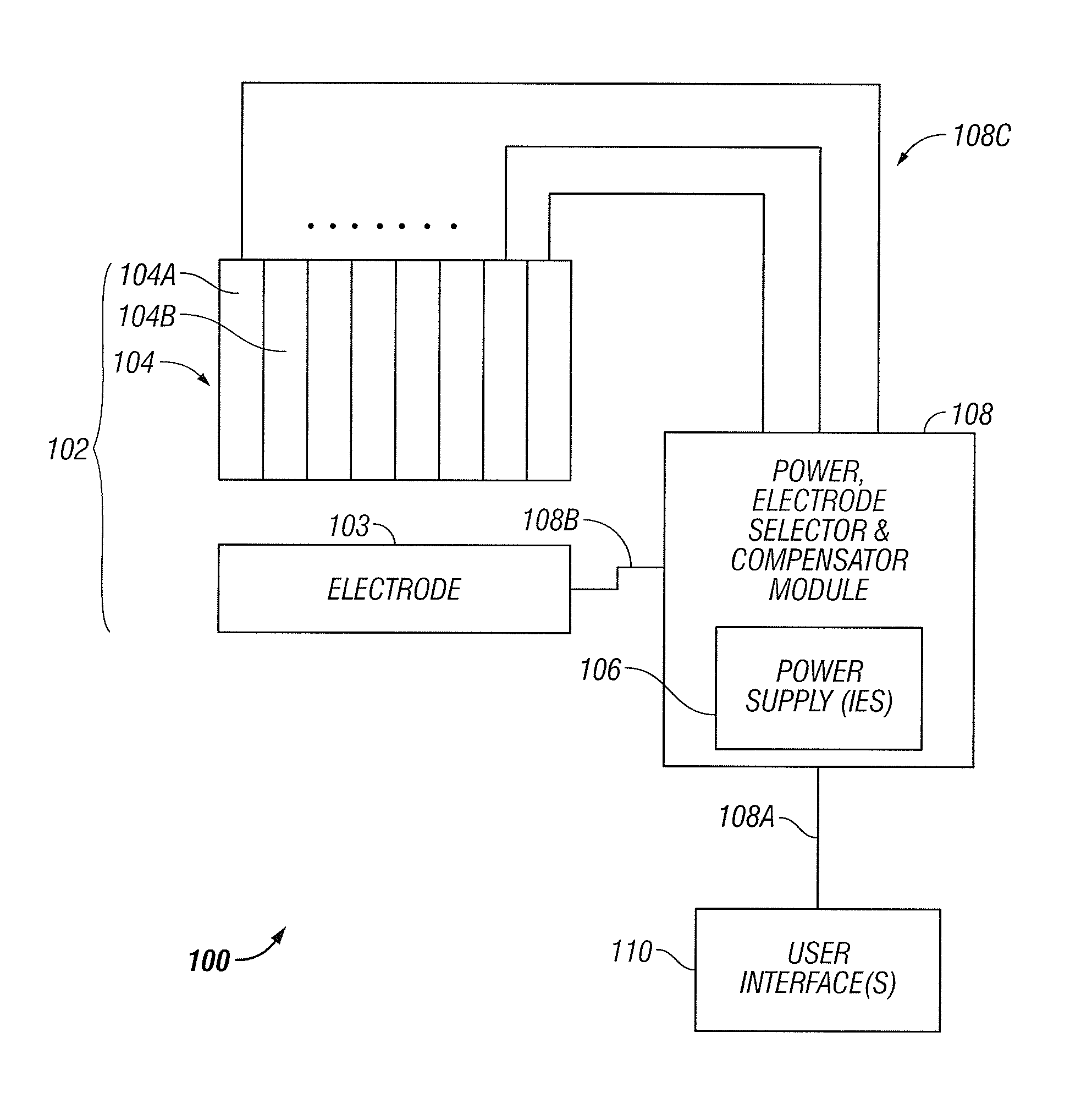
FIG. 1 illustrates one embodiment of electrocautery system 100. The system 100 includes an electrode structure 102 that is electrically driven by a power, electrode selector, and compensator module 108. The module 108 is operated in accordance with user input conveyed via one or more user interfaces 110.
As explained below in greater detail, certain components of the system 100 may be implemented with digital data processing features. These may be implemented in various forms.
Some examples include a general purpose processor, digital signal processor (DSP), application specific integrated circuit (ASIC), field programmable gate array (FPGA) or other programmable logic device, discrete gate or transistor logic, discrete hardware components, or any combination thereof designed to perform the functions described herein. A general purpose processor may be a microprocessor, but in the alternative, the processor may be any conventional processor, controller, microcontroller, or state machine. A processor may also be implemented as a combination of computing devices, e.g. a combination of a DSP and a microprocessor, a plurality of microprocessors, one or more microprocessors in conjunction with a DSP core, or any other such configuration.
As a more specific example, a digital data processing includes a processor, such as a microprocessor, personal computer, workstation, controller, microcontroller, state machine, or other processing machine, coupled to digital data storage. In the present example, the storage includes a fast-access storage, as well as nonvolatile storage. The fast-access storage may be used, for example, to store the programming instructions executed by the processor. Storage may be implemented by various devices. Many alternatives are possible. For instance, one of the components may be eliminated. Furthermore, the storage may be provided on-board the processor, or even provided externally to the apparatus.
The apparatus also includes an input/output, such as a connector, line, bus, cable, buffer, electromagnetic link, antenna, IR port, transducer, network, modem, or other means for the processor to exchange data with other hardware external to the apparatus.
As mentioned above, various instances of digital data storage may be used, for example, to provide storage used by the system 100 (FIG. 1), to embody the storage, etc. Depending upon its application, this digital data storage may be used for various functions, such as storing data, or to store machine-readable instructions. These instructions may themselves aid in carrying out various processing functions, or they may serve to install a software program upon a computer, where such software program is then executable to perform other functions related to this disclosure.
An exemplary storage medium is coupled to a processor so the processor can read information from, and write information to, the storage medium. In the alternative, the storage medium may be integral to the processor. In another example, the processor and the storage medium may reside in an ASIC or other integrated circuit.
In contrast to storage media that contain machine-executable instructions (as described above), a different embodiment uses logic circuitry to implement processing data processing features of the system.
Depending upon the particular requirements of the application in the areas of speed, expense, tooling costs, and the like, this logic may be implemented by constructing an application-specific integrated circuit (ASIC) having thousands of tiny integrated transistors. Such an ASIC may be implemented with CMOS, TTL, VLSI, or another suitable construction. Other alternatives include a digital signal processing chip (DSP), discrete circuitry (such as resistors, capacitors, diodes, inductors, and transistors), field programmable gate array (FPGA), programmable logic array (PLA), programmable logic device (PLD), and the like.
Electrode Structure 102
Referring to FIG. 1, the electrode structure 102 includes first and second electrode surfaces 103-104. The electrode surface 104 is formed by a group of electrodes, such as individual electrodes 104a, 104b, etc. In one instance, the electrodes may be substantially contiguous. The electrode surface 103, in one instance, includes a single electrode, as illustrated. In another instance, the surface 103 includes multiple electrodes, of the same or different number than the electrodes 104.
In one embodiment the electrode surfaces 103-104 are arranged to provide electrical power to a targeted tissue area using opposed, bipolar electrodes. The use of opposed, bipolar electrodes is advantageous because it concentrates energy flux between the electrodes and limits the effect on adjacent tissue that is not confined within the opposed electrodes.
In one case, the electrode structures 103-104 may have generally similar geometries to contact tissue in a symmetric fashion. Alternatively, the electrode structures 103-104 may have dissimilar geometries. For example, one electrode structure may comprise a probe for insertion into a natural body orifice with the other electrode structure being structured to engage an exterior tissue surface apart from the body orifice. In some instances, more than two electrode structures may be employed, but at least two electrode structures, or separate regions of a single structure, are energized with opposite polarity to apply RF energy to the targeted tissue. In some instances, the electrode structures may be different regions formed as part of a single support structure, e.g. a single elastic tube or shell which may be placed over an organ or other tissue mass and which has two or more electrode surfaces formed thereon.
The different electrode surfaces are isolated from each other when high frequency energy of the same or opposite polarity is applied to them. In still other instances, a single electrode structure may have a plurality of electrically conductive or active regions, where the electrically conductive regions may be energized with the same or an opposite polarity.
In some instances, it may be desirable to provide additional structure or components on the electrode structures to enhance or increase the effective electrical contact area between the electrode structure and the tissue. In particular, the electrode structures may include tissue-penetrating elements to enhance electrical contact i.e. reduce electrical impedance between the electrode and the tissue and increase the total surface contact area between the electrode and the tissue. Exemplary tissue-penetrating elements include needles, pins, protrusions, channels, or the like. A particular example includes pins having sharpened distal tips so that they can penetrate through the tissue surface and into the underlying tissue mass. The pins may have depths in the range from 1 mm to 5 cm, or from 3 mm to 1 cm. The diameters of the pins range from 0.1 mm to 5 mm, or from 0.5 mm to 3 mm. In one instance, the pins are evenly distributed over the tissue-contact area of an electrode structure, with a pin density in the range from 0.1 pin/cm.sup.2 to 10 pin/cm.sup.2, or from 0.5 pin/cm.sup.2 to 5 pin/cm.sup.2. When tissue-penetrating elements are used, they may be dispersed in a general uniform matter over the electrically active area of the electrode structure. The pins or other tissue-penetrating elements may be provided in addition to an electrically conductive conformable or rigid electrode surface, but in some instances the pins may provide the total electrically conductive or active area of an electrode structure.
In one example, the electrodes comprise a plurality of different electrically conductive regions, where the regions may be electrically isolated from each other or may be electrically coupled to each other. Single electrode structures may include three, four, five, and as many as ten or more discrete electrically conductive regions thereon. Such electrically conductive regions may be defined by electrically insulating regions or structure between them.
One example of a multiple-electrode surface 104 is a plurality of electrically conductive strips that are separated by a gap which may be an air gap, a plastic member or other insulator. The gap is preferably less than 0.5 mm. In addition, multiple tissue-penetrating pins may be disposed along the length of each electrically conductive strips. The electrically conductive strips may be energized in an alternating polarity configuration. Most simply, opposing strips are connected to opposite polls on a single power supply. Electrical connections may be rearranged, however, to power the strips in virtually any pattern. Moreover, it is also possible to isolate different regions of each strip electrically to permit powering those regions at different polarities; or to set the electrodes to the same polarity but with various sequences of firing pattern that can include firing every electrode, firing specific electrode, or firing multiple electrodes simultaneously.
Although shown as flat plates, the electrode structure 102 may be implemented in a variety of different shapes without departing from the scope of the invention. For instance, the electrode structures 103-104 may be generally curved to facilitate placement over a tubular body structure or tissue mass. In one case, electrode configurations are specifically configured to have a geometry intended to engage a particular organ or tissue geometry. In other cases, the electrode configurations are conformable so that they can be engaged against and conform to widely differing tissue surfaces. In this regard, electrode strips may be constructed from such material as, for example, conformable meshes, permitting the electrode structures to be flattened out or to assume a wide variety of other configurations. Additionally, the insulating structures may also be formed from a flexible or conformable material, permitting further reconfiguration of the electrode structures. The structure 102 may be implemented according in any one, or a combination, of known shapes configurations, which are familiar to the ordinarily skilled artisan. Some exemplary shapes include opposing jaws, cylinder, probe, flat pads, etc. In this regard, the electrodes may be configured in any manner suitable for engaging a tissue surface.
Thus, the electrodes can be rigid, flexible, elastic, inelastic (non-distensible), planar, non-planar, or the like, and may optionally employ tissue-penetrating elements to enhance electrical contact between the electrode structure and the tissue, as well as to increase the electrode area. Electrode configurations may be conformable so that they can be engaged against and conform to widely differing tissue surfaces, or they are specifically configured to have a geometry intended to engage a particular organ or tissue geometry. In both instances, the electrode structures may further be provided with tissue-penetrating elements.
Optionally, electrode structures may include both a conductive surface and a non-conductive surface. In some embodiments this is accomplished by leaving one surface as an exposed metallic face, while the other surface of the electrode is covered or insulated with, for example, a dielectric material. In the case of rigid electrodes, the insulation can be laminated, coated, or otherwise applied directly to the opposed surface. In the case of flexible and elastic electrodes, the insulating layer is flexible so that it can be expanded and contracted together with the electrode without loss or removal. In some cases, a separate, expandable sheet of material covers the face for which insulation is desired. In some embodiments, all electrode surfaces may be coated with a dielectric material.
In one embodiment, the electrically active regions of the electrode structures have an area ranging from one to fifty cm.sup.2 or larger. Further details and examples of electrode structures are explained in the U.S. patent applications as identified incorporated herein by reference above.
Power Supply 106
The power supply 106 includes one or multiple power supplies. Basically, the power supply 106 generates high frequency, such as RF, power for application to targeted tissue through one or more electrically active regions of the electrode structure 102. As described below, the duration and magnitude of power cauterizes or necroses tissue between the electrode surfaces 103-104.
Exemplary frequency bands include 100 kHz to 10 MHz or 200 kHz to 750 kHz. Power levels depend on the surface area and volume of tissue being treated, with some examples including a range from 10 W to 500 W, or 25 W to 250 W, or 50 W to 200 W. Power may be applied at a level of from 1 W/cm.sup.2 to 500 W/cm.sup.2, or 10 W/cm.sup.2 to 100 W/cm.sup.2, for example.
The power supply 106 may be implemented using various conventional general purpose electrosurgical power supplies. The power supply 106 may employ sinusoidal or non-sinusoidal wave forms and may operate with fixed or controlled power levels. Suitable power supplies are available from commercial suppliers.
In one embodiment, the power supply provides a constant output power, with variable voltage and current, where power output varies based upon load. Thus, if the system sees a very high impedance load, the voltage is maintained at a reasonable level to avoid arcing. With tissue electrocautery, impedance ranges from two ohms to 1000 ohms, for example. By applying constant power, the power supply 106 can provide significant current at low impedance to achieve initial desiccation when the tissue is first being cauterized and, as cauterization proceeds, to apply higher voltage to complete the tissue sealing process. Thus, the power supply 106 can provide larger current and smaller voltage at the beginning of the cauterization process and a higher voltage and lower current at the sealing phase of the process. Control of such power generator is based, at least in part, on the system 100 monitoring power.
In one embodiment, the power supply 106 includes a mechanism for setting the desired power. This setting may occur by real-time control, pre-set selection by a user, default settings, selection of predetermined profile, etc. In one embodiment, pulse width modulation is used in connection with a flyback transformer. The system charges a primary of the flyback transformer and produces a regulated output. The secondary may be regulated, for example, to 15 volts at a desired number of amperes to produce the desired power output. Based upon the period, as determined by the width of the pulse which charges the primary, the power curve is determined. Thus, the invention establishes a certain level of power in the primary of the flyback transformer and the same level of power is provided by the secondary without regard to impedance of the load, i.e. the tissue.
The power supply 106 may include digital data processing equipment, such as mentioned above. This optional equipment, if implemented, is used to establish and control features and operation of the power supply 106.
As illustrated, the power supply 106 is a source of power for multiple electrodes of the structure 102. Accordingly, the power supply 106, or the module 108, provides multiple output channels, each of which is independently adjustable. In this embodiment, the system 100 includes a conductive supply path of multiple conductors 108c to provide power to the electrodes, and a return path 108b for providing a ground path and/or feedback to the power supply or vice versa, depending on the direction of current flow.
In a more particular embodiment, the module 108 has multiple outputs 108c routed to the individual electrodes by a digital data processor of the module 108. These multiple outputs are independently operated by the processor and readily modulated and assignable. Thus, the processor may assign an output to any one or more of the electrode elements at a certain point in operation of a cauterization cycle, and dynamically reassign them other points of time. For example, if the power source were a four channel power source and the electro-surgical device had sixteen electrodes, then each channel may support four electrodes in electro-surgical device. However, this arrangement may be varied so that some channels support more electrodes than others.
User Interface 110
The user interface 110 comprises one or more devices for a human to exchange information with the module 108, including the power supply 106. There may be a common user interface, or separate user interfaces for each component 106, 108. The user interface may be implemented in various ways, with the following serving as some examples. As for human-to-machine flow, some examples of the interface 110 include buttons, dials, switches, keyboards, remote control console, or other mechanical devices. Other examples include pointing devices such as a mouse, trackball, etc. Still other examples include digitizing pads, touch screens, voice input, or any other example suitable for the purposes described herein. As for the machine-to-human exchange, the interface 110 may employ a video monitor, display screen, LEDs, mechanical indicators, audio system, or other example suitable for the purposes described herein.
User input is conveyed from the interface to the module 108 via the link 108a.
Sensors
The system 100 may also include various sensors attached to various components of the system 100. The sensors, which are not shown in FIG. 1 to avoid cluttering the diagram, may be attached to components such as the electrodes 103-104, subparts of the module 108, equipment of the power supply 106, and the like. Examples of these sensors include devices for sensing voltage, current, impedance, phase angle between applied voltage and current, temperature, energy, frequency, etc. More particular, some of these devices include voltmeters, analog-to-digital converters, thermistors, transducers, ammeters, etc.
Module 108
As shown above, the module 108 includes one or more power supplies 106. Aside from this function, module 108 may be implemented to perform some or all of automated or user-selected operation or compensation of the electrodes in the manner shown below. According to one aspect, the module 108 may be used to target a specific region of tissue, or the control firing order of electrodes, by selectively limiting power application to electrodes whose selection is predetermined, machine-selected, or user-selected. According to another aspect, the module 108 may introduce impedance into the electrode circuitry to provide a predetermined, machine-selected, or user-selected impedance matching or compensation.
According to one optional aspect of the module 108, the module 108 may target a specific region of tissue by selectively limiting power application to electrodes whose selection is predetermined, machine-selected, or user-selected. In this regard, the module 108 has a variety of outputs 108b-108c individually coupled to each of the electrodes 103-104. As one example, the outputs 108b-108c may comprise wires, cables, busses, or other electrical conductors. In the illustrated example, there are multiple conductors 108c leading to the multiple electrodes 104a, 104b, etc.
The module 108 applies voltage from the power supply 106 across the first and second electrode surfaces 103-104, such that the voltage is applied exclusively to selected ones of the electrodes. These electrodes may be selected according to user input from the interface 110, selected by a machine-implemented analysis, and/or selected by a default state. In this regard, the module 108 may include a switching network of electrical and/or mechanical switches, relays, or other mechanism to provide power to selected ones of the electrodes. As shown, the power supply 106 is integrated into the module 108, and computer control selectively activates selected output conductors.
Whether by independent switching network or computer regulated activation of output conductors, the module 108 activates electrodes according to input from user interface 110, or input from a machine such as a digital data processing device as discussed above. Depending upon the nature of the application, such controlled application of power to electrodes may be performed in accordance with a machine-selected criteria or analysis, default state, or user input.
FIG. 5 illustrates a typical application of one example of a processor-controlled switching network, shown in context of two power supplies, electrode structures, and a targeted tissue region. In this example, the electrode surfaces are configured as follows. The electrode surfaces are substantially parallel during performance of electrocautery, each electrode of one surface is aligned with its counterpart in the other electrode surface. In this example, there are two electrodes from the upper surface corresponding to each electrode of the lower surface.
Significantly, the module 108 selectively limits power application to certain electrodes, to target a specific region of tissue. Electrodes may be selected for a different end, as well. Namely, the module 108 may monitor or control the selection of electrodes to prevent firing of adjacent electrodes of the same electrode surface concurrently or sequentially. Ensuring that electrode firing occurs in this spaced-apart fashion prevents unintentional arcing between electrodes and improves the effectiveness of electrocautery. In one embodiment, the controlled firing order is implemented by computer control, and particularly, by a digital data processing component of the module 108. As an alternative to computer control, mechanical means may be used, such as an electromechanical distributor or other device.
In another embodiment, the module 108 may introduce impedance into the electrode circuitry to provide predetermined, machine-selected, fixed, or user-selected impedance matching or compensation. In other words, the module 108 contains a mechanism to electrically introduce impedance into a circuit containing the power supply, the outputs 108b-108c, and the electrodes 103-104.
More particularly, the module 108 includes capacitors, inductors, and/or other impedance elements that can be adjusted or selectively introduced to control the amount of impedance in the circuit containing the power supply and electrodes 103-104. These impedance elements may comprise discrete elements, integrated circuit features, or other constructs suitable for the purposes described herein. The module 108 establishes this impedance matching or compensation according to directions from a user, machine-implemented analysis, and/or default setting.
One example of an adjustable impedance is an adjustable inductor that may comprise any known inductance, such as a coil of conducting material wrapped around an adjustable ferromagnetic core or discrete inductors. In this example, the overall inductance is selectively increased by closing a switch that may be activated manually, mechanically, electrically, or by any means suitable to the purposes of this disclosure, for example, via the user interface 110.
FIG. 2 illustrates an electrode arrangement having an inductance in series with each electrode of an upper electrode surface (as illustrated). FIG. 3 shows a different example, including an inductance in series with each electrode of the lower electrode surface (as illustrated). In a different example still, FIG. 4 contains "T" type network where a capacitor is placed in series with each electrode of the upper electrode surface. Additionally, a different inductor is placed in parallel with each pair of electrodes that are designed to be activated together. The examples of FIGS. 2-4 may employ impedance elements that are fixed, adjustable, or a combination of fixed and adjustable. Furthermore, in connection with the electrodes having a dielectric coating on their surface, a nearly limitless number of additional circuitry configurations for impedance matching and/or compensation will be apparent to ordinarily skilled artisans having the benefit of this disclosure.
In addition to the arrangement for introducing impedance into the electrode circuits, another consideration is the value of such impedance elements. In one example, the impedance is selected to achieve maximum power transfer and to make accurate power measurements. In this regard, the impedance is chosen to maintain an impedance match between the RF generator, namely, the power supply 106, and the tissue. Impedance matching is achieved when the phase-angle between applied voltage and current is zero. Namely, additional inductance is increased to compensate for the increased capacitive reactance. In one example, this is carried out with a continuously variable inductor, with a finite range and nearly infinite resolution. Such an inductor can be adjusted to a near zero phase. In a different example, impedance matching is carried out by using discrete inductive elements in an appropriate arrangement, such as shown in FIGS. 2-4, to find the least possible phase angle, though this may not be exactly zero.
Having described the structural features of the invention, the operational aspects of the invention will be described. The steps of any method, process, or algorithm described in connection with the embodiments disclosed herein may be embodied directly in hardware, in a software module executed by hardware, human-performed steps, or a combination of these.
A sequence for performing an electrocautery procedure uses an electrocautery system that includes an electrode structure and a mechanism for automated or user-selected operation or compensation of the electrodes. For ease of explanation, but without any intended limitation, this example is described in the specific context of the system 100 of FIG. 1.
In a first step, different parameters for operating the system 100 are selected. In one example, one or more human users select these parameters and convey them to the system 100 via the user interface 110. In a different example, the parameters for operating the system 100 are selected by digital data processing equipment aboard the module 108. In this case, the parameters are set according to user input, default values, measurements gathered by the various sensors installed in the system 102, programming of the module 108, etc.
Without any intended limitation, the following are some non-exclusive examples of parameters that may be selected in the first step: (1) Identity of individual electrodes to be activated e.g., FIG. 5 in order to focus energy of the electrodes 103-104 on a specific region of tissue. (2) Firing order of electrodes. (3) Assessment or measurement of magnitude of impedance, e.g. FIGS. 2-4, to be used in compensating and/or impedance matching between the power supply 106 and electrodes 103-104. (4) Parameters of electrical power to be applied in electrocautery, such as magnitude, frequency, phase, or other characteristics of voltage, current, power, etc. (5) Any other parameter by which the operation of the system 100 can be varied.
In a next step appropriately trained personnel apply the electrodes 103-104 to a targeted tissue region to be electrocauterized. The manner of applying the electrodes 103-104, varies according to the construction of the electrodes 103-104, the nature of the targeted body part, the procedure to be performed, and other such factors. There may be circumstances where both electrode structures 103-104 are used within the body, and other embodiments where one electrode is inserted into the body and the other electrode used externally, i.e. bipolar or monopolar applications, as is know in the art.
In a specific example of this next step, there are multiple electrodes of one surface, such as 104, corresponding to one electrode of the other surface, such as 103. Optionally, personnel arrange the first and second electrode surfaces 103-104 so that the electrode surfaces are substantially parallel, and each one of the second electrodes is aligned with its corresponding first electrodes, although alignment is preferably obtained during manufacture of the device. FIGS. 2-5 show examples of the final arrangement.
In a further step, directions are given to begin electrocautery. This occurs by user input submitted via the interface 110. For example, a user may press a start button, utter a start command, press a foot pedal, trip a lever, or perform other action. In a different example, electronically occurs upon expiration of a user-initiated timer.
In a still further step, the system 100 responds to the start command and electrocautery is conducted. Here, the system 100 directs bipolar RF power at target tissue regions defined by spaced-apart placement of the electrode structures 103-104. The use of opposed, bipolar electrodes concentrates energy between the electrodes and limits the effect on adjacent tissue that is not confined within the opposed electrodes. In practice, power may be applied for a time sufficient to raise the tissue temperature in the tissue mass being treated to above a threshold level required for cauterization or necrosis, such as 60-80.degree. C., or even higher.
More specifically, electrocautery is conducted according to the configuration set. For instance, the power supply 106 operates according to the power settings established. Moreover, the module 108 acts to invoke individual ones of the electrodes according to the electrode combination selected. In other words, the module 108 applies voltage from the power supply 106 across the first and second electrode surfaces 103-104, such that voltage is applied exclusively to the electrodes selected in. In the case of computer control, this is achieved by the module 108 selectively applying power to the selected electrodes.
As a further enhancement to the use of selected electrodes, the electrodes may be activated using a selected firing order. In this example, the module 108 applies voltage from the power supply 106 across the first and second electrode surfaces 103-104, such that voltage is applied to one or more of the first electrodes 102 and one or more of the second electrodes 103 at any one time, and the module 108 prevents firing of adjacent electrodes of the same electrode surface concurrently or sequentially. The module 108 may further implement a predetermined or user-selected firing order.
For example, one way of preventing interaction, either thermal or electrical, between two or more multiple electrodes in an RF device with multiple electrodes is to alter the firing sequence of electrodes so that adjacent electrodes are never sequentially charged. For example, instead of sequential firing a four electrode system, where the electrodes are sequentially numbered 1, 2, 3, 4, the invention fires them in an order such as 3, 1, 4, 2, 4, 2, 4, 1, 3, 1, 3, etc. so that adjacent electrodes are not fired sequentially. Firing times may be different for each electrode to balance the energy delivered in such a sequence where some electrodes fire more frequently than others. This prevents cross-talk during the transmission from one electrode to another as well as cumulative effects of sequential heat build-up in the transition area between the two electrodes. Additionally, rounded electrodes can minimize the edge effect that occurs between electrodes and at any transition surface.
Additionally, if one electrode surface or both opposing surface of conductive, typically metal, electrodes are coated with dielectric, non-conductive materials, RF energy may still be transmitted through tissue between them via capacitive coupling. FIG. 6 is a block diagram showing an electrode having a dielectric coating according to the invention. However, due to the non-conductive nature of the surface coating the electrode surfaces does not create a short circuit if brought into close proximity or contact. In this way, if a portion of an electrode pair only partially captures tissue, i.e. there is a small, 5 mm air gap between a portion of the electrodes, the RF energy still passes through the tissue, as opposed to going around the tissue and flowing directly between the close proximity electrodes. This is especially important late in the sealing cycle as the tissue impedance rises. When the tissue impedance is high the energy seeks alternate pathways of lower resistance, such as between exposed electrode sections. These dielectric layers can be thin coats of polymers, such as Teflon, metal oxides, such as titanium, tungsten, or tantalum or ceramics. To obtain adequate capacitance these layers may be in the micron range of thickness.
In an alternative embodiment, a variety of different tissue cauterization patterns can be achieved with the system 100 by selectively energizing different ones of the electrode surfaces or regions. By selectively energizing two adjacent electrodes, while leaving all other electrodes non-energized, a limited tissue region is cauterized. In contrast, by energizing other multiple electrode surfaces, a larger region is cauterized. Slightly different patterns are achieved depending on the precise pattern of electrode surface polarity. In other embodiments, the electrode surfaces can be energized in an alternating pattern of polarity to produce a tissue cauterization pattern. Different patterns may also be used to produce somewhat different patterns of cauterized tissue.
A different approach for selected firing is employed to prevent local areas of high impedance from impacting the overall system impedance along the entire electrode, and thus potentially reducing the power output of the entire system as voltage reaches its maximal capacity. Here, electrodes are activated to prevent one area that has already been well sealed and has thus reached high impedance value from affecting other regions in which the tissue is not yet sealed, and is thus at a lower impedance. Optionally, the module 108 may employ unique power and energy delivery profiles for each electrode or electrode pair, based on the properties of the tissue in a specific electrode location/position.
The performance of electrocautery employs the selected impedance compensation and/or matching selected. As a result, power delivered from the power supply 106 is delivered to the targeted tissue region with less electrical loss.
The system 100 may further sense and automatically adjust conjugate matching impedance. In response, the module 108 adjusts the impedance applied to the conductive path containing the electrode surfaces 103-104 and power supply 106. Alternatively, the sensors may provide raw data to the module 108, which analyzes whether and how to adjust impedance. In a different instance, the module 108 may adjust impedance responsive to direction or data from the sensors. This can be carried out by changing the frequency of RF energy delivered by the power supply 106. For example, in one embodiment the module 108 senses whether or not tissue is present at each electrode at the beginning of a cauterization cycle by measuring any of impedance, pressure, or any combination of these and/or other parameters. If tissue is not present at any electrode, then such electrode pair is idle; the module 108 deactivates firing of this electrode, and/or provides a warning to an operator via the user interface 110. The module 108 may also provide a status indicator for each electrode pair that indicates whether the sealing cycle is active or completed with regard to each electrode pair. In this embodiment, each electrode pair may include a mode status indicator, such as an LED for example, that indicates any of an idle, active, or complete condition, once a cauterization cycle is commenced.
The invention also addresses the problem of determining the area of tissue coverage of one or more electrodes through the use of dielectric coated electrode surfaces (See FIG. 6). With a suitable RF generator and with electrode surfaces coated with a dielectric coating, determination of tissue coverage may be obtained by measuring phase-angle of RF voltage and current. Because a dielectric coating essentially forms a capacitive coupling to tissue, for a given dielectric material thickness, the capacitance is a function of the area of coverage.
The basic formula for a capacitor is: C=.epsilon..sub.0.epsilon..sub.rA/d
Expressed in Farads, where .epsilon..sub.0 is the permittivity of free-space (8.854E-12), .epsilon..sub.r, is the relative permittivity of the dielectric, A/d is the ratio of the area and the dielectric thickness.
At a given frequency, the reactance is expressed as Xc=1/.omega.C where .omega. is 2*Pi*Frequency.
A suitable RF generator is required to insert a conjugate impedance inductance in this case to cancel out the capacitive reactance with a fully covered electrode and to measure the phase-angle of RF voltage and current. When an electrode is only partially covered, the capacitance changes i.e. becomes smaller, because the effective area is smaller. As a result, the reactance and, ultimately, the phase-angle of RF voltage and current change. While the magnitude of change is affected in part by the tissue resistance, it is believed that this methodology allows the greatest degree of determination of electrode coverage by tissue.
A further advantage of such a methodology may signal the RF generator's control algorithm to change frequency, e.g. increase, with smaller surface areas, thus maintaining maximum power transfer while minimizing chances for electrical arcing and tissue charring. Potential electrical arcing and tissue charring conditions may be detected rapidly by rapid changes in phase and/or impedance and by appreciating that electrodes which are only partially covered by tissue may be used to signal the RF generator control algorithm to shorten or change treatment parameters.
To achieve maximum power transfer and to make accurate power measurements, it is desirable to maintain an impedance match between the RF generator and the tissue. Impedance matching is achieved when the phase-angle is zero. Several methodologies may be used to attain near-zero phase. One such methodology uses additional reactive elements e.g. greater inductance, to compensate for the increased capacitive reactance. This approach can be achieved in two different ways: (1) Via the insertion of a continuously variable inductor with a finite range and nearly infinite resolution, such an inductor can be adjusted to a near zero phase; or (2) Via the insertion of discrete elements, e.g. inductors to find the lowest phase, though this may not be near-zero phase.
In both cases, electromechanical devices are required within the RF generator.
Another methodology of achieving maximum power-transfer, e.g. zero phase, is by changing the RF frequency. Given that the reactance is frequency dependent, this methodology allows the RF generator to compensate for phase discrepancy by electronically changing frequency. This may not require any mechanical devices such as relays, servos, etc. Further, the RF generator can change frequency during operation rather than first interrupting RF power to change elements. Thus, this may be the most desirable methodology.
Although the invention is described herein with reference to the preferred embodiment, one skilled in the art will readily appreciate that other applications may be substituted for those set forth herein without departing from the spirit and scope of the present invention. Accordingly, the invention should only be limited by the Claims included below.
* * * * *
References
-
sages.org/01program/syllabi/ho1/ho1.html#schirmer
-
gyrusgroup.com/medical/products_item.asp?id=11
-
-
-
-
-
ncbi.nlm.nih.gov/entrez/query.fcgi?cmd=Retrieve&db=pubmed&dopt=Abstract&list_uids=10459037&query_hl=1
-
obgmanagement.com/supplements/pdf/hysterectomy.pdf
-
jnjgateway.com/home.jhtml?loc=USENG&page=viewContent&contentId=edea000100001747&parentId=fc0de00100000334
-
valleylab.com/product/es/accessories/forceps_over.html
-
-
erbe-med.com/erbe/media/Marketingmaterialien/85100-139_ERBE_EN_BiClampD024676.pdf
-
gyrusacmi.com/user/display.cfm?display=product&pid=9024
-
onemedplace.com/database/compdisplay_print.php?CompanyID=11508
-
arxiv.org/abs/nucl-th/9502001v1
-
sages.org/01program/syllabi/nurse/nurse.html
-
starioninstruments.com/PDFs/Treat.pdf
-
locateadoc.com/Site_Tools/Print.cfm
D00000
D00001
D00002
D00003
D00004
D00005
D00006
XML
uspto.report is an independent third-party trademark research tool that is not affiliated, endorsed, or sponsored by the United States Patent and Trademark Office (USPTO) or any other governmental organization. The information provided by uspto.report is based on publicly available data at the time of writing and is intended for informational purposes only.
While we strive to provide accurate and up-to-date information, we do not guarantee the accuracy, completeness, reliability, or suitability of the information displayed on this site. The use of this site is at your own risk. Any reliance you place on such information is therefore strictly at your own risk.
All official trademark data, including owner information, should be verified by visiting the official USPTO website at www.uspto.gov. This site is not intended to replace professional legal advice and should not be used as a substitute for consulting with a legal professional who is knowledgeable about trademark law.