System for cooling an electronic image assembly with circulating gas and ambient gas
Hubbard
U.S. patent number 10,314,212 [Application Number 15/407,131] was granted by the patent office on 2019-06-04 for system for cooling an electronic image assembly with circulating gas and ambient gas. This patent grant is currently assigned to MANUFACTURING RESOURCES INTERNATIONAL, INC.. The grantee listed for this patent is Manufacturing Resources International, Inc.. Invention is credited to Tim Hubbard.


| United States Patent | 10,314,212 |
| Hubbard | June 4, 2019 |
System for cooling an electronic image assembly with circulating gas and ambient gas
Abstract
An apparatus for cooling an electronic image assembly with ambient gas and circulating gas is disclosed. A first fan may be positioned to force the circulating gas around the electronic image assembly in a closed loop while a second fan may be positioned to cause a flow of ambient gas. A structure is preferably positioned to allow the circulating gas to cross the flow of the ambient gas while substantially prohibiting the circulating gas from mixing with the ambient gas. A pair of manifolds may be placed along the sides of the electronic image assembly and may be in gaseous communication with a plurality of channels placed behind the electronic image assembly. A heat exchanger may be used in some exemplary embodiments.
| Inventors: | Hubbard; Tim (Alpharetta, GA) | ||||||||||
|---|---|---|---|---|---|---|---|---|---|---|---|
| Applicant: |
|
||||||||||
| Assignee: | MANUFACTURING RESOURCES
INTERNATIONAL, INC. (Alpharetta, GA) |
||||||||||
| Family ID: | 45996364 | ||||||||||
| Appl. No.: | 15/407,131 | ||||||||||
| Filed: | January 16, 2017 |
Prior Publication Data
| Document Identifier | Publication Date | |
|---|---|---|
| US 20170127579 A1 | May 4, 2017 | |
Related U.S. Patent Documents
| Application Number | Filing Date | Patent Number | Issue Date | ||
|---|---|---|---|---|---|
| 14664213 | Mar 20, 2015 | 9549490 | |||
| 14300869 | Mar 24, 2015 | 8988647 | |||
| 13100556 | Jun 10, 2014 | 8749749 | |||
| 12905704 | Jul 8, 2014 | 8773633 | |||
| 12641468 | Feb 18, 2014 | 8654302 | |||
| 12706652 | Jan 22, 2013 | 8358397 | |||
| 12952745 | Apr 8, 2014 | 8693185 | |||
| 61331340 | May 4, 2010 | ||||
| 61252295 | Oct 16, 2009 | ||||
| 61138736 | Dec 18, 2008 | ||||
| 61152879 | Feb 16, 2009 | ||||
| 61321364 | Apr 6, 2010 | ||||
| Current U.S. Class: | 1/1 |
| Current CPC Class: | H05K 7/20145 (20130101); H05K 7/20172 (20130101); H05K 7/20127 (20130101); H05K 7/20954 (20130101); G02F 1/133308 (20130101); G02F 2201/36 (20130101); G02F 2001/13332 (20130101); G02F 2001/133628 (20130101) |
| Current International Class: | H05K 7/20 (20060101); G02F 1/1333 (20060101); G02F 1/1335 (20060101) |
| Field of Search: | ;349/161 ;361/692 |
References Cited [Referenced By]
U.S. Patent Documents
| 4093355 | June 1978 | Kaplit et al. |
| 4593978 | June 1986 | Mourey et al. |
| 4634225 | January 1987 | Haim et al. |
| 4748765 | June 1988 | Martin |
| 4763993 | August 1988 | Vogeley et al. |
| 4921041 | May 1990 | Akachi |
| 4952783 | August 1990 | Aufderheide et al. |
| 4952925 | August 1990 | Haastert |
| 5029982 | July 1991 | Nash |
| 5088806 | February 1992 | McCartney et al. |
| 5132666 | July 1992 | Fahs |
| 5247374 | September 1993 | Terada |
| 5282114 | January 1994 | Stone |
| 5293930 | March 1994 | Pitasi |
| 5351176 | September 1994 | Smith et al. |
| 5432526 | July 1995 | Hyatt |
| 5535816 | July 1996 | Ishida |
| 5559614 | September 1996 | Urbish et al. |
| 5621614 | April 1997 | O'Neill |
| 5657641 | August 1997 | Cunningham et al. |
| 5748269 | May 1998 | Harris et al. |
| 5765743 | June 1998 | Sakiura et al. |
| 5767489 | June 1998 | Ferrier |
| 5808418 | September 1998 | Pitman et al. |
| 5818010 | October 1998 | McCann |
| 5818694 | October 1998 | Daikoku et al. |
| 5835179 | November 1998 | Yamanaka |
| 5864465 | January 1999 | Liu |
| 5869818 | February 1999 | Kim |
| 5869919 | February 1999 | Sato et al. |
| 5903433 | May 1999 | Gudmundsson |
| 5991153 | November 1999 | Heady et al. |
| 6003015 | December 1999 | Kang et al. |
| 6007205 | December 1999 | Fujimori |
| 6043979 | March 2000 | Shim |
| 6089751 | July 2000 | Conover et al. |
| 6104451 | August 2000 | Matsuoka et al. |
| 6125565 | October 2000 | Hillstrom |
| 6157432 | December 2000 | Helbing |
| 6181070 | January 2001 | Dunn et al. |
| 6191839 | February 2001 | Briley et al. |
| 6198222 | March 2001 | Chang |
| 6211934 | April 2001 | Habing et al. |
| 6215655 | April 2001 | Heady et al. |
| 6351381 | February 2002 | Bilski et al. |
| 6392727 | May 2002 | Larson et al. |
| 6417900 | July 2002 | Shin et al. |
| 6473150 | October 2002 | Takushima et al. |
| 6476883 | November 2002 | Salimes et al. |
| 6493440 | December 2002 | Gromatsky et al. |
| 6504713 | January 2003 | Pandolfi et al. |
| 6535266 | March 2003 | Nemeth et al. |
| 6628355 | September 2003 | Takahara |
| 6701143 | March 2004 | Dukach et al. |
| 6714410 | March 2004 | Wellhofer |
| 6727468 | April 2004 | Nemeth |
| 6742583 | June 2004 | Tikka |
| 6812851 | November 2004 | Dukach et al. |
| 6825828 | November 2004 | Burke et al. |
| 6839104 | January 2005 | Taniguchi et al. |
| 6850209 | February 2005 | Mankins et al. |
| 6885412 | April 2005 | Ohnishi et al. |
| 6886942 | May 2005 | Okada et al. |
| 6891135 | May 2005 | Pala et al. |
| 6909486 | June 2005 | Wang et al. |
| 6943768 | September 2005 | Cavanaugh et al. |
| 6961108 | November 2005 | Wang et al. |
| 7015470 | March 2006 | Faytlin et al. |
| 7059757 | June 2006 | Shimizu |
| 7083285 | August 2006 | Hsu et al. |
| 7157838 | January 2007 | Thielemans et al. |
| 7161803 | January 2007 | Heady |
| 7190416 | March 2007 | Paukshto et al. |
| 7190587 | March 2007 | Kim et al. |
| 7209349 | April 2007 | Chien et al. |
| 7212403 | May 2007 | Rockenfeller |
| 7259964 | August 2007 | Yamamura et al. |
| 7269023 | September 2007 | Nagano |
| 7284874 | October 2007 | Jeong et al. |
| 7396145 | July 2008 | Wang et al. |
| 7452121 | November 2008 | Cho et al. |
| 7457113 | November 2008 | Kumhyr et al. |
| 7480140 | January 2009 | Hara et al. |
| 7535543 | May 2009 | Dewa et al. |
| 7591508 | September 2009 | Chang |
| 7602469 | October 2009 | Shin |
| D608775 | January 2010 | Leung |
| 7667964 | February 2010 | Kang et al. |
| 7682047 | March 2010 | Hsu et al. |
| 7752858 | July 2010 | Johnson et al. |
| 7753567 | July 2010 | Kang et al. |
| 7762707 | July 2010 | Kim et al. |
| 7800706 | September 2010 | Kim et al. |
| 7813124 | October 2010 | Karppanen |
| 7903416 | March 2011 | Chou |
| 7995342 | August 2011 | Nakamichi et al. |
| 8004648 | August 2011 | Dunn |
| 8035968 | October 2011 | Kwon et al. |
| 8081465 | December 2011 | Nishiura |
| 8102173 | January 2012 | Merrow |
| 8142027 | March 2012 | Sakai |
| 8208115 | June 2012 | Dunn |
| 8223311 | July 2012 | Kim et al. |
| 8241573 | August 2012 | Banerjee et al. |
| 8248784 | August 2012 | Nakamichi et al. |
| 8254121 | August 2012 | Lee et al. |
| 8269916 | September 2012 | Ohkawa |
| 8270163 | September 2012 | Nakamichi et al. |
| 8274622 | September 2012 | Dunn |
| 8274789 | September 2012 | Nakamichi et al. |
| 8300203 | October 2012 | Nakamichi et al. |
| 8320119 | November 2012 | Isoshima et al. |
| 8351014 | January 2013 | Dunn |
| 8358397 | January 2013 | Dunn |
| 8369083 | February 2013 | Dunn et al. |
| 8373841 | February 2013 | Dunn |
| 8379182 | February 2013 | Dunn |
| 8400608 | March 2013 | Takahashi et al. |
| 8472174 | June 2013 | Idems et al. |
| 8472191 | June 2013 | Yamamoto et al. |
| 8482695 | July 2013 | Dunn |
| 8497972 | July 2013 | Dunn et al. |
| 8590602 | November 2013 | Fernandez |
| 8649170 | February 2014 | Dunn et al. |
| 8649176 | February 2014 | Okada et al. |
| 8654302 | February 2014 | Dunn et al. |
| 8678603 | March 2014 | Zhang |
| 8693185 | April 2014 | Dunn et al. |
| 8700226 | April 2014 | Schuch et al. |
| 8711321 | April 2014 | Dunn et al. |
| 8749749 | June 2014 | Hubbard |
| 8755021 | June 2014 | Hubbard |
| 8758144 | June 2014 | Williams et al. |
| 8760613 | June 2014 | Dunn |
| 8767165 | July 2014 | Dunn |
| 8773633 | July 2014 | Dunn et al. |
| 8804091 | August 2014 | Dunn et al. |
| 8823916 | September 2014 | Hubbard et al. |
| 8827472 | September 2014 | Takada |
| 8854572 | October 2014 | Dunn |
| 8854595 | October 2014 | Dunn |
| 8879042 | November 2014 | Dunn |
| 8976313 | March 2015 | Kim et al. |
| 8988647 | March 2015 | Hubbard |
| 9030641 | May 2015 | Dunn |
| 9089079 | July 2015 | Dunn |
| 9119325 | August 2015 | Dunn et al. |
| 9119330 | August 2015 | Hubbard et al. |
| 9173322 | October 2015 | Dunn |
| 9173325 | October 2015 | Dunn |
| 9282676 | March 2016 | Diaz |
| 9285108 | March 2016 | Dunn et al. |
| 9313917 | April 2016 | Dunn et al. |
| 9370127 | June 2016 | Dunn |
| 9448569 | September 2016 | Schuch et al. |
| 9451060 | September 2016 | Bowers et al. |
| 9451733 | September 2016 | Dunn et al. |
| 9456525 | September 2016 | Yoon et al. |
| 9470924 | October 2016 | Dunn et al. |
| 9500896 | November 2016 | Dunn et al. |
| 9516485 | December 2016 | Bowers et al. |
| 9549490 | January 2017 | Hubbard |
| 9594271 | March 2017 | Dunn et al. |
| 9613548 | April 2017 | DeMars |
| 9622392 | April 2017 | Bowers et al. |
| 9629287 | April 2017 | Dunn |
| 9648790 | May 2017 | Dunn et al. |
| 9655289 | May 2017 | Dunn et al. |
| 9703320 | July 2017 | Bowers et al. |
| 9723765 | August 2017 | DeMars |
| 9823690 | November 2017 | Bowers et al. |
| 9835893 | December 2017 | Dunn |
| 9894800 | February 2018 | Dunn |
| 10080316 | September 2018 | Dunn et al. |
| 10088702 | October 2018 | Dunn et al. |
| 10194564 | January 2019 | Dunn et al. |
| 2001/0001459 | May 2001 | Savant et al. |
| 2001/0019454 | September 2001 | Tadic-Galeb et al. |
| 2002/0009978 | January 2002 | Dukach et al. |
| 2002/0033919 | March 2002 | Sanelle et al. |
| 2002/0050793 | May 2002 | Cull et al. |
| 2002/0065046 | May 2002 | Mankins et al. |
| 2002/0084891 | July 2002 | Mankins et al. |
| 2002/0101553 | August 2002 | Enomoto et al. |
| 2002/0112026 | August 2002 | Fridman et al. |
| 2002/0126248 | September 2002 | Yoshia |
| 2002/0148600 | October 2002 | Bosch et al. |
| 2002/0149714 | October 2002 | Anderson et al. |
| 2002/0154255 | October 2002 | Gromatzky et al. |
| 2002/0164944 | November 2002 | Haglid |
| 2002/0164962 | November 2002 | Mankins et al. |
| 2002/0167637 | November 2002 | Burke et al. |
| 2003/0007109 | January 2003 | Park |
| 2003/0020884 | January 2003 | Okada et al. |
| 2003/0043091 | March 2003 | Takeuchi et al. |
| 2003/0104210 | June 2003 | Azumi et al. |
| 2003/0128511 | July 2003 | Nagashima et al. |
| 2003/0214785 | November 2003 | Perazzo |
| 2004/0012722 | January 2004 | Alvarez |
| 2004/0035032 | February 2004 | Milliken |
| 2004/0035558 | February 2004 | Todd et al. |
| 2004/0036622 | February 2004 | Dukach et al. |
| 2004/0036834 | February 2004 | Ohnishi et al. |
| 2004/0042174 | March 2004 | Tomioka et al. |
| 2004/0103570 | June 2004 | Ruttenberg |
| 2004/0105159 | June 2004 | Saccomanno et al. |
| 2004/0135482 | July 2004 | Thielemans et al. |
| 2004/0165139 | August 2004 | Anderson et al. |
| 2004/0223299 | November 2004 | Ghosh |
| 2005/0012039 | January 2005 | Faytlin et al. |
| 2005/0012722 | January 2005 | Chon |
| 2005/0062373 | March 2005 | Kim et al. |
| 2005/0073632 | April 2005 | Dunn et al. |
| 2005/0073639 | April 2005 | Pan |
| 2005/0127796 | June 2005 | Olesen et al. |
| 2005/0134525 | June 2005 | Tanghe et al. |
| 2005/0134526 | June 2005 | Willem et al. |
| 2005/0213950 | September 2005 | Yoshimura |
| 2005/0229630 | October 2005 | Richter et al. |
| 2005/0237714 | October 2005 | Ebermann |
| 2005/0253699 | November 2005 | Madonia |
| 2005/0276053 | December 2005 | Nortrup et al. |
| 2005/0286131 | December 2005 | Saxena et al. |
| 2006/0012958 | January 2006 | Tomioka et al. |
| 2006/0018093 | January 2006 | Lai et al. |
| 2006/0034051 | February 2006 | Wang et al. |
| 2006/0056994 | March 2006 | Van Lear et al. |
| 2006/0082271 | April 2006 | Lee et al. |
| 2006/0092348 | May 2006 | Park |
| 2006/0125998 | June 2006 | Dewa et al. |
| 2006/0132699 | June 2006 | Cho et al. |
| 2006/0177587 | August 2006 | Ishizuka et al. |
| 2006/0199514 | September 2006 | Kimura |
| 2006/0209266 | September 2006 | Utsunomiya |
| 2006/0260790 | November 2006 | Theno et al. |
| 2006/0262079 | November 2006 | Seong et al. |
| 2006/0266499 | November 2006 | Choi et al. |
| 2006/0269216 | November 2006 | Wiemeyer et al. |
| 2006/0283579 | December 2006 | Ghosh et al. |
| 2007/0013647 | January 2007 | Lee et al. |
| 2007/0019419 | January 2007 | Hafuka et al. |
| 2007/0030879 | February 2007 | Hatta |
| 2007/0047239 | March 2007 | Kang et al. |
| 2007/0065091 | March 2007 | Hinata et al. |
| 2007/0076431 | April 2007 | Atarashi et al. |
| 2007/0081344 | April 2007 | Cappaert et al. |
| 2007/0103863 | May 2007 | Kim |
| 2007/0103866 | May 2007 | Park |
| 2007/0115686 | May 2007 | Tyberghien |
| 2007/0139929 | June 2007 | Yoo et al. |
| 2007/0140671 | June 2007 | Yoshimura |
| 2007/0151274 | July 2007 | Roche et al. |
| 2007/0151664 | July 2007 | Shin |
| 2007/0171353 | July 2007 | Hong |
| 2007/0206158 | September 2007 | Kinoshita et al. |
| 2007/0211205 | September 2007 | Shibata |
| 2007/0212211 | September 2007 | Chiyoda et al. |
| 2007/0217221 | September 2007 | Lee et al. |
| 2007/0237636 | October 2007 | Hsu |
| 2007/0267174 | November 2007 | Kim |
| 2008/0035315 | February 2008 | Han |
| 2008/0055534 | March 2008 | Kawano |
| 2008/0076342 | March 2008 | Bryant et al. |
| 2008/0099193 | May 2008 | Aksamit et al. |
| 2008/0148609 | June 2008 | Ogoreve |
| 2008/0209934 | September 2008 | Richards |
| 2008/0218446 | September 2008 | Yamanaka |
| 2008/0236005 | October 2008 | Isayev et al. |
| 2008/0267790 | October 2008 | Gaudet et al. |
| 2008/0283234 | November 2008 | Sagi et al. |
| 2008/0285290 | November 2008 | Ohashi et al. |
| 2008/0310116 | December 2008 | O'Connor |
| 2009/0009047 | January 2009 | Yanagawa et al. |
| 2009/0009729 | January 2009 | Sakai |
| 2009/0059518 | March 2009 | Kakikawa et al. |
| 2009/0065007 | March 2009 | Wilkinson et al. |
| 2009/0086430 | April 2009 | Kang et al. |
| 2009/0120629 | May 2009 | Ashe |
| 2009/0122218 | May 2009 | Oh et al. |
| 2009/0126906 | May 2009 | Dunn |
| 2009/0126907 | May 2009 | Dunn |
| 2009/0126914 | May 2009 | Dunn |
| 2009/0135365 | May 2009 | Dunn |
| 2009/0147170 | June 2009 | Oh et al. |
| 2009/0154096 | June 2009 | Iyengar et al. |
| 2009/0174626 | July 2009 | Isoshima et al. |
| 2009/0231807 | September 2009 | Bouissiere |
| 2009/0244472 | October 2009 | Dunn |
| 2009/0279240 | November 2009 | Karppanen |
| 2009/0302727 | December 2009 | Vincent et al. |
| 2009/0306820 | December 2009 | Simmons et al. |
| 2009/0323275 | December 2009 | Rehmann et al. |
| 2010/0060861 | March 2010 | Medin |
| 2010/0079949 | April 2010 | Nakamichi et al. |
| 2010/0162747 | July 2010 | Hamel et al. |
| 2010/0171889 | July 2010 | Pantel et al. |
| 2010/0182562 | July 2010 | Yoshida et al. |
| 2010/0220249 | September 2010 | Nakamichi et al. |
| 2010/0226091 | September 2010 | Dunn |
| 2010/0232107 | September 2010 | Dunn |
| 2010/0238394 | September 2010 | Dunn |
| 2010/0321887 | December 2010 | Kwon et al. |
| 2011/0001898 | January 2011 | Mikubo et al. |
| 2011/0013114 | January 2011 | Dunn et al. |
| 2011/0019363 | January 2011 | Vahlsing et al. |
| 2011/0051071 | March 2011 | Nakamichi et al. |
| 2011/0058326 | March 2011 | Idems et al. |
| 2011/0072697 | March 2011 | Miller |
| 2011/0075361 | March 2011 | Nakamichi et al. |
| 2011/0083460 | April 2011 | Thomas et al. |
| 2011/0083824 | April 2011 | Rogers |
| 2011/0085301 | April 2011 | Dunn |
| 2011/0085302 | April 2011 | Nakamichi et al. |
| 2011/0114384 | May 2011 | Sakamoto et al. |
| 2011/0116000 | May 2011 | Dunn et al. |
| 2011/0116231 | May 2011 | Dunn et al. |
| 2011/0122162 | May 2011 | Sato et al. |
| 2011/0141724 | June 2011 | Erion |
| 2011/0261523 | October 2011 | Dunn et al. |
| 2012/0006523 | January 2012 | Masahiro et al. |
| 2012/0012295 | January 2012 | Kakiuchi et al. |
| 2012/0012300 | January 2012 | Dunn et al. |
| 2012/0014063 | January 2012 | Weiss |
| 2012/0020114 | January 2012 | Miyamoto et al. |
| 2012/0038849 | February 2012 | Dunn et al. |
| 2012/0044217 | February 2012 | Okada et al. |
| 2012/0106081 | May 2012 | Hubbard et al. |
| 2012/0188481 | July 2012 | Kang et al. |
| 2012/0206687 | August 2012 | Dunn et al. |
| 2012/0249402 | October 2012 | Kang |
| 2012/0255704 | October 2012 | Nakamichi |
| 2012/0274876 | November 2012 | Cappaert et al. |
| 2012/0284547 | November 2012 | Culbert et al. |
| 2013/0170140 | July 2013 | Dunn |
| 2013/0173358 | July 2013 | Pinkus |
| 2013/0176517 | July 2013 | Kim et al. |
| 2013/0201685 | August 2013 | Messmore et al. |
| 2013/0258659 | October 2013 | Erion |
| 2013/0279154 | October 2013 | Dunn |
| 2013/0294039 | November 2013 | Chao |
| 2014/0044147 | February 2014 | Wyatt et al. |
| 2014/0085564 | March 2014 | Hendren et al. |
| 2014/0111758 | April 2014 | Dunn et al. |
| 2014/0113540 | April 2014 | Dunn et al. |
| 2014/0134767 | May 2014 | Ishida et al. |
| 2014/0313698 | October 2014 | Dunn et al. |
| 2014/0314395 | October 2014 | Dunn et al. |
| 2015/0009627 | January 2015 | Dunn et al. |
| 2015/0253611 | September 2015 | Yang et al. |
| 2015/0264826 | September 2015 | Dunn et al. |
| 2015/0319882 | November 2015 | Dunn et al. |
| 2015/0366101 | December 2015 | Dunn et al. |
| 2016/0041423 | February 2016 | Dunn |
| 2016/0044829 | February 2016 | Dunn |
| 2016/0192536 | June 2016 | Diaz |
| 2016/0195254 | July 2016 | Dunn et al. |
| 2016/0198588 | July 2016 | DeMars |
| 2016/0238876 | August 2016 | Dunn et al. |
| 2016/0242329 | August 2016 | DeMars |
| 2016/0242330 | August 2016 | Dunn |
| 2016/0249493 | August 2016 | Dunn et al. |
| 2016/0302331 | October 2016 | Dunn |
| 2017/0023823 | January 2017 | Dunn et al. |
| 2017/0068042 | March 2017 | Dunn et al. |
| 2017/0074453 | March 2017 | Bowers et al. |
| 2017/0083043 | March 2017 | Bowers et al. |
| 2017/0083062 | March 2017 | Bowers et al. |
| 2017/0111486 | April 2017 | Bowers et al. |
| 2017/0111520 | April 2017 | Bowers et al. |
| 2017/0111521 | April 2017 | Bowers et al. |
| 2017/0127579 | May 2017 | Hubbard |
| 2017/0140344 | May 2017 | Bowers et al. |
| 2017/0147992 | May 2017 | Bowers et al. |
| 2017/0163519 | June 2017 | Bowers et al. |
| 2017/0175411 | June 2017 | Bowers et al. |
| 2017/0188490 | June 2017 | Dunn et al. |
| 2017/0245400 | August 2017 | Dunn et al. |
| 2017/0332523 | November 2017 | DeMars |
| 2018/0042134 | February 2018 | Dunn et al. |
| 2018/0116073 | April 2018 | Dunn |
| 2018/0314103 | November 2018 | Dunn et al. |
| 2018/0315356 | November 2018 | Dunn et al. |
| 2018/0317330 | November 2018 | Dunn et al. |
| 2018/0317350 | November 2018 | Dunn et al. |
| 2018/0364519 | December 2018 | Dunn et al. |
| 2019/0037738 | January 2019 | Dunn et al. |
| 2011248190 | May 2011 | AU | |||
| 2017216500 | Aug 2017 | AU | |||
| 2014287438 | Jan 2018 | AU | |||
| 2015253128 | Mar 2018 | AU | |||
| 2017216500 | Jan 2019 | AU | |||
| 2705814 | Feb 2018 | CA | |||
| 2947524 | Apr 2018 | CA | |||
| 2915261 | Aug 2018 | CA | |||
| 2809019 | Sep 2018 | CA | |||
| 2702363 | May 2005 | CN | |||
| 108700739 | Oct 2018 | CN | |||
| 1408476 | Apr 2004 | EP | |||
| 1647766 | Apr 2006 | EP | |||
| 1762892 | Mar 2007 | EP | |||
| 1951020 | Jul 2008 | EP | |||
| 2225603 | Sep 2010 | EP | |||
| 2370987 | Oct 2011 | EP | |||
| 2603831 | Jun 2013 | EP | |||
| 2801888 | Nov 2014 | EP | |||
| 2909829 | Aug 2015 | EP | |||
| 3020260 | May 2016 | EP | |||
| 3117693 | Jan 2017 | EP | |||
| 3259968 | Dec 2017 | EP | |||
| 3423886 | Jan 2019 | EP | |||
| 2402205 | Dec 2004 | GB | |||
| 402062015 | Mar 1990 | JP | |||
| 402307080 | Dec 1990 | JP | |||
| 3153212 | Jul 1991 | JP | |||
| H062337 | Jan 1994 | JP | |||
| 6082745 | Mar 1994 | JP | |||
| 8115788 | May 1996 | JP | |||
| 8194437 | Jul 1996 | JP | |||
| H08305301 | Nov 1996 | JP | |||
| 8339034 | Dec 1996 | JP | |||
| H09246766 | Sep 1997 | JP | |||
| 11160727 | Jun 1999 | JP | |||
| H11296094 | Oct 1999 | JP | |||
| 2000010501 | Jan 2000 | JP | |||
| 2001209126 | Aug 2001 | JP | |||
| 2002158475 | May 2002 | JP | |||
| 2004053749 | Feb 2004 | JP | |||
| 2004199675 | Jul 2004 | JP | |||
| 2004286940 | Oct 2004 | JP | |||
| 2005017556 | Jan 2005 | JP | |||
| 2000131682 | May 2005 | JP | |||
| 2005134849 | May 2005 | JP | |||
| 2005265922 | Sep 2005 | JP | |||
| 2006513577 | Apr 2006 | JP | |||
| 2007322718 | May 2006 | JP | |||
| 2006148047 | Jun 2006 | JP | |||
| 2006163217 | Jun 2006 | JP | |||
| 2007003638 | Jan 2007 | JP | |||
| 09307257 | Nov 2007 | JP | |||
| 2007293105 | Nov 2007 | JP | |||
| 2008010361 | Jan 2008 | JP | |||
| 2008292743 | Dec 2008 | JP | |||
| 2010024624 | Feb 2010 | JP | |||
| 2010102227 | May 2010 | JP | |||
| 2010282109 | Dec 2010 | JP | |||
| 2011503663 | Jan 2011 | JP | |||
| 2011075819 | Apr 2011 | JP | |||
| 2012133254 | Jul 2012 | JP | |||
| 2013537721 | Oct 2013 | JP | |||
| 2014225595 | Dec 2014 | JP | |||
| 6305564 | Apr 2018 | JP | |||
| 2018511838 | Apr 2018 | JP | |||
| 20000000118 | Jan 2000 | KR | |||
| 20000047899 | Jul 2000 | KR | |||
| 20040067701 | Jul 2004 | KR | |||
| 200366674 | Nov 2004 | KR | |||
| 20050033986 | Apr 2005 | KR | |||
| 200401354 | Nov 2005 | KR | |||
| 20060016469 | Feb 2006 | KR | |||
| 100666961 | Jan 2007 | KR | |||
| 1020070070675 | Apr 2007 | KR | |||
| 1020070048294 | Aug 2007 | KR | |||
| 101764381 | Jul 2017 | KR | |||
| 10-1847151 | Apr 2018 | KR | |||
| 10-1853885 | Apr 2018 | KR | |||
| 10-1894027 | Aug 2018 | KR | |||
| 101904363 | Sep 2018 | KR | |||
| 2513043 | Apr 2014 | RU | |||
| WO2005079129 | Aug 2005 | WO | |||
| WO2007116116 | Oct 2007 | WO | |||
| WO2008050660 | May 2008 | WO | |||
| WO2009065125 | May 2009 | WO | |||
| WO2009065125 | May 2009 | WO | |||
| WO2009135308 | Nov 2009 | WO | |||
| WO2010007821 | Feb 2010 | WO | |||
| WO2010080624 | Jul 2010 | WO | |||
| WO2011069084 | Jun 2011 | WO | |||
| WO2011072217 | Jun 2011 | WO | |||
| WO2011140179 | Nov 2011 | WO | |||
| WO2011150078 | Dec 2011 | WO | |||
| WO2012021573 | Feb 2012 | WO | |||
| WO2012024426 | Feb 2012 | WO | |||
| 2013182733 | Dec 2013 | WO | |||
| WO2014149773 | Sep 2014 | WO | |||
| WO2014150036 | Sep 2014 | WO | |||
| WO2015168375 | Nov 2015 | WO | |||
| WO2016102982 | Jun 2016 | WO | |||
| 2016127613 | Aug 2016 | WO | |||
| WO2016133852 | Aug 2016 | WO | |||
| 2018200260 | Nov 2018 | WO | |||
| 2018200905 | Nov 2018 | WO | |||
Other References
|
Itsenclosures, Product Catalog, 2009, 48 pages. cited by applicant . Itsenclosures, Standard Product Data Sheet, 2011, 18 pages. cited by applicant . Sunbritetv, All Weather Outdoor LCD Television Model 4610HD, 2008, 1 page. cited by applicant . Sunbritetv, Introduces Two New All-Weather Outdoor Televisions InfoComm 2008, 7 pages. cited by applicant . Itsenclosures, Viewstation, 2017, 16 pages. cited by applicant . Novitsky, Driving LEDs versus CCFLs for LCD backlighting, Nov. 12, 2007, 6 pages. cited by applicant . Federman, Cooling Flat Panel Displays, 2011, 4 pages. cited by applicant . Zeeff, T.M., EMC analysis of an 18'' LCD monitor, 2000, 1 page. cited by applicant . Vertigo Digital Displays, Innovation on Display FlexVu Totem Brochure, 2014, 6 pages. cited by applicant . Vertigo Digital Displays, FlexVu Totem Shelter, 2017, 2 pages. cited by applicant . Vertigo Digital Displays, All Products Catalogue, 2017,14 pages. cited by applicant . Adnation,Turn Key Advertising Technology Solutions, May 23, 2017, 4 pages. cited by applicant . CIVIQ Smartscapes, FlexVue Ferro 55P/55L, Mar. 16, 2017, 4 pages. cited by applicant . Wankhede, Evaluation of Cooling Solutions for Outdoor Electronics, Sep. 17-19, 2007, 6 pages. cited by applicant . Bureau of Ships Navy Department, Guide Manual of Cooling methods for Electronic Equipment, Mar. 31, 1955, 212 pages. cited by applicant . CIVIQ, Invalidity Claim Charts, Appendix A--Appendix D, Jan. 24, 2018, 51 pages. cited by applicant . CIVIQ, Invalidity Contentions, Jan. 24, 2018, 51 pages. cited by applicant . Scott, Cooling of Electronic Equipment, Apr. 4, 1947, 119 pages. cited by applicant . Sergent, Thermal Management Handbook for Electronic Assemblies, Aug. 14, 1998, 190 pages. cited by applicant . Steinberg, Cooling Techniques for Electronic Equipment First Edition, 1980, 255 pages. cited by applicant . Steinberg, Cooling Techniques for Electronic Equipment Second Edition, 1991, 299 pages. cited by applicant . Yeh, Thermal Management of Microelectronic Equipment, Oct. 15, 2002, 148 pages. cited by applicant . CIVIQ Smartscapes LLC. v. Manufacturing Resources International, Inc., Petition for Inter Partes Review of U.S. Pat. No. 8,854,572 including Declaration of Greg Blonder in Support of Petition, Curriculum Vitae of Greg Blonder and Prosecution History of U.S. Pat. No. 8,854,572, Petition filed Mar. 14, 2018, 427 pages. cited by applicant . The American Heritage College Dictionary, Third Edition, 1993, excerpt, 3 pages, Houghton Mifflin Company. cited by applicant . Mentley, David E., State of Flat-Panel Display Technology and Future Trends, Proceedings of the IEEE, Apr. 2002, vol. 90, No. 4, pp. 453-459. cited by applicant . Rohsenow, Warren M., Handbook of Heat Transfer, Third Edition, 1998, select chapters, 112 pages, McGraw-Hill. cited by applicant . CIVIQ, Invalidity Claim Chart, Appendix I, Mar. 22, 2018, 4 pages. cited by applicant . CIVIQ, Invalidity Claim Charts, Appendix F to H, Mar. 22, 2018, 18 pages. cited by applicant . CIVIQ Smartscapes LLC. v. Manufacturing Resources International, Inc., Defendant's Amended Answer and Countercliams to Plaintiff's First Amended Complaint, Filed Apr. 24, 2018, 240 pages. cited by applicant . Yung, Using Metal Core Printed Circuit Board as a Solution for Thermal Management article, 2007, 5 pages. cited by applicant . CIVIQ Smartscapes, LLC v. Manufacturing Resources International, Inc., Memorandum Opinion re claim construction, Sep. 27, 2018, 16 pages. cited by applicant . CIVIQ Smartscapes, LLC v. Manufacturing Resources International, Inc., Claim Construction Order, Oct. 3, 2018, 2 pages. cited by applicant . Anandan, Munismay, Progress of LED backlights for LCDs, Journal of the SID, 2008, pp. 287-310, 16/2. cited by applicant. |
Primary Examiner: Blevins; Jerry M
Attorney, Agent or Firm: Standley Law Group LLP Standley; Jeffrey S. Norris; Jeffrey C.
Parent Case Text
CROSS-REFERENCE TO RELATED APPLICATIONS
This application is a continuation of U.S. application Ser. No. 14/664,213, filed on Mar. 20, 2015, now U.S. Pat. No. 9,549,490, issued Jan. 17, 2017, which is a continuation of U.S. application Ser. No. 14/300,869, filed on Jun. 10, 2014, now U.S. Pat. No. 8,988,647, issued Mar. 24, 2015, which is a continuation of U.S. application Ser. No. 13/100,556, filed on May 4, 2011, now U.S. Pat. No. 8,749,749, issued Jun. 10, 2014. U.S. application Ser. No. 13/100,556 is a non-provisional of U.S. Application No. 61/331,340, filed May 4, 2010. U.S. application Ser. No. 13/100,556 is also a continuation-in-part of U.S. application Ser. No. 12/905,704, filed Oct. 15, 2010, which is a non-provisional of U.S. Application No. 61/252,295, filed Oct. 16, 2009. U.S. application Ser. No. 13/100,556 is also a continuation-in-part of U.S. application Ser. No. 12/641,468, filed Dec. 18, 2009, now U.S. Pat. No. 8,654,302, issued Feb. 18, 2014, which is a non-provisional of U.S. Application No. 61/138,736, filed Dec. 18, 2008. U.S. application Ser. No. 13/100,556 is also a continuation-in-part of U.S. application Ser. No. 12/706,652, filed Feb. 16, 2010, now U.S. Pat. No. 8,358,397, issued Jan. 22, 2013, which is a non-provisional application of U.S. Application No. 61/152,879, filed Feb. 16, 2009. U.S. application Ser. No. 13/100,556 is also a continuation-in-part of U.S. application Ser. No. 12/952,745, filed Nov. 23, 2010, now U.S. Pat. No. 8,693,185, issued Apr. 8, 2014, which is a non-provisional of U.S. Application No. 61/321,364, filed Apr. 6, 2010. All aforementioned applications are hereby incorporated by reference in their entirety as if fully cited herein.
Claims
The invention claimed is:
1. An apparatus comprising: an electronic image assembly; a housing assembly containing said electronic image assembly; a first fan connected to said housing assembly and adapted to circulate gas in a first path through an interior of said housing assembly; a second fan connected to said housing assembly and adapted to cause ambient gas from outside said housing assembly to circulate in a second path through said interior of said housing assembly; and a structure positioned within said housing assembly and configured to allow the gas in said first path to cross over the ambient gas in said second path.
2. The apparatus of claim 1 wherein said second fan is adapted to circulate the ambient gas in said second path, which goes behind the electronic image assembly.
3. The apparatus of claim 1 further comprising a plurality of channels behind said electronic image assembly, each said channel having an inlet and an exit configured to accept ambient gas.
4. The apparatus of claim 3 further comprising: a first manifold in gaseous communication with said inlet of each said channel; and a second manifold in gaseous communication with said exit of each said channel.
5. The apparatus of claim 4 wherein said first manifold and said second manifold are respectively placed along a pair of vertical edges of said electronic image assembly.
6. The apparatus of claim 3 wherein said channels are in thermal communication with said electronic image assembly.
7. The apparatus of claim 1 wherein said structure comprises a first series of voids configured to accept the gas in said first path and a second series of voids configured to accept the ambient gas in said second path.
8. The apparatus of claim 1 wherein said structure comprises a first and a second series of voids wherein said first series of voids are oriented substantially perpendicular to said second series of voids.
9. The apparatus of claim 1 wherein said first path crosses over said second path at a right angle.
10. An apparatus comprising: an electronic image assembly; a housing assembly containing said electronic image assembly; a first fan connected to said housing assembly and adapted to circulate gas in a first path through said housing assembly; a second fan connected to said housing assembly and adapted to cause ambient gas to circulate in a second path through said housing assembly; and a structure comprising a first series of voids configured to accept the gas in said first path and a second series of voids configured to accept the ambient gas in said second path; wherein said first series of voids is oriented substantially perpendicular to said second series of voids.
11. The apparatus of claim 10 further comprising a channel in front of said electronic image assembly such that said first fan is adapted to circulate the gas in said first path through said front channel.
12. The apparatus of claim 10 further comprising a plurality of channels behind said electronic image assembly, each said channel having an inlet and an exit configured to accept ambient gas.
13. The apparatus of claim 12 further comprising: a first manifold in gaseous communication with said inlet of each said channel; and a second manifold in gaseous communication with said exit of each said channel.
14. The apparatus of claim 10 wherein said structure is configured to substantially separate the gas in said first path from the ambient gas in said second path.
15. The apparatus of claim 10 further comprising a heat exchanger configured to accept the gas in said first path in addition to a second flow of ambient gas.
16. An apparatus comprising: an electronic image assembly; a first fan adapted to circulate gas around said electronic image assembly in a first path; a second fan adapted to circulate a first flow of ambient gas; a first structure on a first side of said electronic image assembly configured to allow the gas in said first path to cross over the first flow of ambient gas; a second structure on a second side of said electronic image assembly configured to allow the gas in said first path to cross over the first flow of ambient gas; and a heat exchanger configured to accept the gas in said first path and a second flow of ambient gas.
17. The apparatus of claim 16 further comprising: a first manifold adjacent to said first structure; and a second manifold adjacent to said second structure.
18. The apparatus of claim 16 wherein said first structure and said second structure each comprise a first series of voids configured to accept the gas in said first path and a second series of voids configured to accept the first flow of ambient gas.
19. The apparatus of claim 16 wherein said first structure and said second structure each comprise a first series of voids and a second series of voids such that said first series of voids is oriented substantially perpendicular to said second series of voids.
20. The apparatus of claim 16 wherein said first structure and said second structure are each configured to substantially separate the gas in said first path from the first flow of ambient gas.
Description
TECHNICAL FIELD
Exemplary embodiments generally relate to cooling systems and in particular to cooling systems for electronic displays.
BACKGROUND OF THE ART
Improvements to electronic displays now allow them to be used in outdoor environments for informational, advertising, or entertainment purposes. While displays of the past were primarily designed for operation near room temperature, it is now desirable to have displays which are capable of withstanding large surrounding environmental temperature variations. For example, some displays are capable of operating at temperatures as low as -22 F and as high as 113 F or higher. When surrounding temperatures rise, the cooling of the internal display components can become even more difficult.
Additionally, modern displays have become extremely bright, with some backlights producing 1,000-2,000 nits or more. Sometimes, these illumination levels are necessary because the display is being used outdoors, or in other relatively bright areas where the display illumination must compete with other ambient light. In order to produce this level of brightness, illumination devices and electronic displays may produce a relatively large amount of heat.
Still further, in some situations radiative heat transfer from the sun through a front display surface can also become a source of heat. In some locations 800-1400 Watts/m.sup.2 or more through such a front display surface is common. Furthermore, the market is demanding larger screen sizes for displays. With increased electronic display screen size and corresponding front display surfaces, more heat will be generated and more heat will be transmitted into the displays.
Exemplary modern displays have found some effective means for cooling the displays including circulating a closed loop of gas around the display and drawing ambient gas through the display so that the closed loop of gas may be cooled (as well as portions of the electronic display). Various thermal communications have been discovered which can transfer heat away from the sensitive electronic components and out of the display. Heat exchangers were found to produce an excellent means for transferring heat between the closed loop of gas and the ambient gas. However, previous designs for moving the gas through the display have been found to generate an undesirable amount of noise emission from the display as well as thermal gradients where portions of the display were cooled but others remained warm.
When using LCD displays, it was found that backlights were often a source of heat and it was desirable to move gas across the rear surface of the backlight in order to cool it. While desirable, it was thought that the front surface of the backlight could not be cooled for fear that the backlight cavity would become contaminated with dust, dirt, or other particulate.
SUMMARY OF THE EXEMPLARY EMBODIMENTS
Exemplary embodiments use a combination of circulating gas and ambient gas in order to adequately cool an electronic display. Circulating gas may be used to remove heat from the front of the image assembly. When using a LCD as the electronic image assembly, circulating gas may also be used to remove heat from the backlight cavity of the LCD. Because the gas is only circulating within the display, it can remain free of particulate and contaminates and will not harm the display.
Ambient gas may be ingested into the display in order to cool the circulating gas. The ambient gas and the circulating gas may be drawn through a heat exchanger which will allow the heat to transfer from the circulating gas to the ambient gas, preferably without letting the ambient and circulating gases mix with one another. An exemplary embodiment would use a cross-flow heat exchanger. An additional flow of ambient gas can be drawn across the rear surface of the image assembly to remove heat from the rear portion of the image assembly. When using a LCD as the electronic image assembly, this additional flow of ambient gas can be used to remove heat from the rear portion of the backlight for the LCD.
In order to reduce noise emissions, the fans which drive the ambient and/or circulating gas through the heat exchanger may be placed within the heat exchanger, which can then act as a muffler and reduce the noise emitted by the fans. Further, if using the additional ambient gas pathway behind the image assembly, a manifold may be used to collect the ambient gas along an edge of the display and distribute this into a number of smaller flows. The fans for driving this additional ambient gas pathway can be placed within the manifold in order to reduce the noise emitted by the fans and provide an even distribution of ambient gas across the display.
It has been found that ingesting ambient gas from the top or bottom edge of the display is preferable as these edges are not typically observable to the viewer. However, when ingesting ambient gas from the top or bottom of a portrait-oriented display, it has been found that as the cool ambient gas travels across the rear portion of the electronic image assembly and accepts heat it increases in temperature. Once the cooling air reaches the opposite edge (either top or bottom), it may have increased in temperature substantially and may no longer provide adequate cooling to the opposing portion of the display. Thus, the manifolds herein allow for cool ambient air to adequately cool the entire electronic image assembly in an even manner and reduce any `hot spots` within the electronic image assembly.
The foregoing and other features and advantages will be apparent from the following more detailed description of the particular embodiments of the invention, as illustrated in the accompanying drawings.
BRIEF DESCRIPTION OF THE DRAWINGS
A better understanding of an exemplary embodiment will be obtained from a reading of the following detailed description and the accompanying drawings wherein identical reference characters refer to identical parts and in which:
FIG. 1A provides a front perspective view of an exemplary embodiment of the electronic display.
FIG. 1B provides a rear perspective view of an exemplary embodiment of the electronic display.
FIG. 2 provides a rear perspective view similar to that shown in FIG. 1B where the rear cover has been removed.
FIG. 3 provides a perspective sectional view along the A-A section line shown in FIG. B.
FIG. 4 provides a perspective sectional view along the B-B section line shown in FIG. 1B.
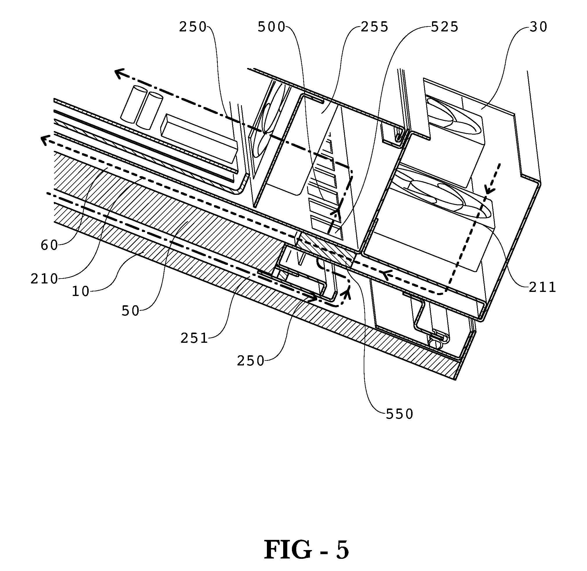
FIG. 5 provides a perspective sectional view of insert C shown in FIG. 4.
FIG. 6 provides a perspective sectional view of one embodiment of the cross through plate.
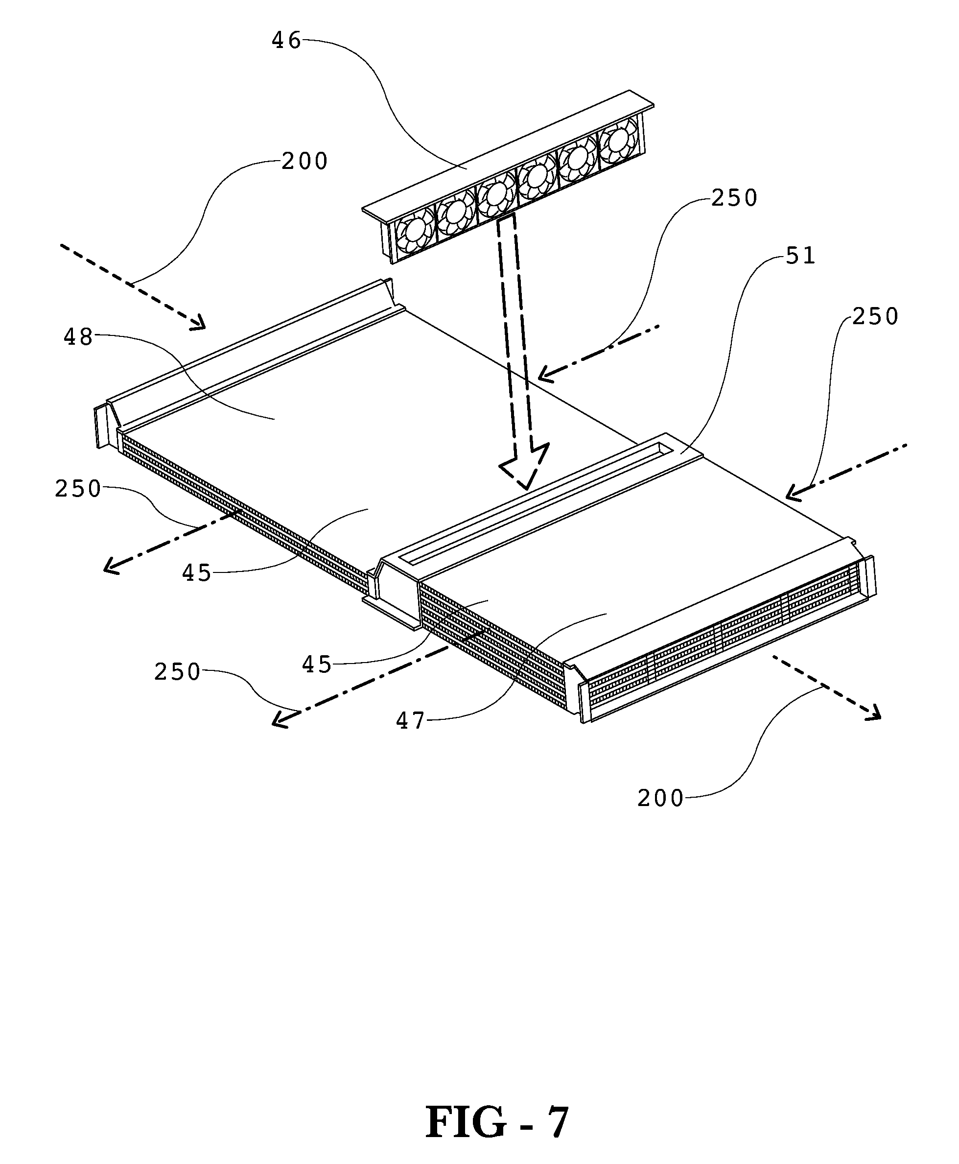
FIG. 7 provides an exploded perspective view of one exemplary embodiment of the heat exchanger and fan assembly.
FIG. 8 provides a perspective sectional view of another embodiment which uses a flow of circulating gas through the backlight cavity of a liquid crystal display (LCD).
FIG. 9 provides a perspective sectional view of an exemplary embodiment which uses a flow of circulating gas through the backlight cavity in addition to the flow of circulating gas between the LCD and front plate.
DETAILED DESCRIPTION
The invention is described more fully hereinafter with reference to the accompanying drawings, in which exemplary embodiments of the invention are shown. This invention may, however, be embodied in many different forms and should not be construed as limited to the exemplary embodiments set forth herein. Rather, these embodiments are provided so that this disclosure will be thorough and complete, and will fully convey the scope of the invention to those skilled in the art. In the drawings, the size and relative sizes of layers and regions may be exaggerated for clarity.
It will be understood that when an element or layer is referred to as being "on" another element or layer, the element or layer can be directly on another element or layer or intervening elements or layers. In contrast, when an element is referred to as being "directly on" another element or layer, there are no intervening elements or layers present. Like numbers refer to like elements throughout. As used herein, the term "and/or" includes any and all combinations of one or more of the associated listed items.
It will be understood that, although the terms first, second, third, etc., may be used herein to describe various elements, components, regions, layers and/or sections, these elements, components, regions, layers and/or sections should not be limited by these terms. These terms are only used to distinguish one element, component, region, layer or section from another region, layer or section. Thus, a first element, component, region, layer or section discussed below could be termed a second element, component, region, layer or section without departing from the teachings of the present invention.
Spatially relative terms, such as "lower", "upper" and the like, may be used herein for ease of description to describe the relationship of one element or feature to another element(s) or feature(s) as illustrated in the figures. It will be understood that the spatially relative terms are intended to encompass different orientations of the device in use or operation, in addition to the orientation depicted in the figures. For example, if the device in the figures is turned over, elements described as "lower" relative to other elements or features would then be oriented "upper" relative the other elements or features. Thus, the exemplary term "lower" can encompass both an orientation of above and below. The device may be otherwise oriented (rotated 90 degrees or at other orientations) and the spatially relative descriptors used herein interpreted accordingly.
The terminology used herein is for the purpose of describing particular embodiments only and is not intended to be limiting of the invention. As used herein, the singular forms "a", "an" and "the" are intended to include the plural forms as well, unless the context clearly indicates otherwise. It will be further understood that the terms "comprises" and/or "comprising," when used in this specification, specify the presence of stated features, integers, steps, operations, elements, and/or components, but do not preclude the presence or addition of one or more other features, integers, steps, operations, elements, components, and/or groups thereof.
Embodiments of the invention are described herein with reference to cross-section illustrations that are schematic illustrations of idealized embodiments (and intermediate structures) of the invention. As such, variations from the shapes of the illustrations as a result, for example, of manufacturing techniques and/or tolerances, are to be expected. Thus, embodiments of the invention should not be construed as limited to the particular shapes of regions illustrated herein but are to include deviations in shapes that result, for example, from manufacturing.
For example, an implanted region illustrated as a rectangle will, typically, have rounded or curved features and/or a gradient of implant concentration at its edges rather than a binary change from implanted to non-implanted region. Likewise, a buried region formed by implantation may result in some implantation in the region between the buried region and the surface through which the implantation takes place. Thus, the regions illustrated in the figures are schematic in nature and their shapes are not intended to illustrate the actual shape of a region of a device and are not intended to limit the scope of the invention.
Unless otherwise defined, all terms (including technical and scientific terms) used herein have the same meaning as commonly understood by one of ordinary skill in the art to which this invention belongs. It will be further understood that terms, such as those defined in commonly used dictionaries, should be interpreted as having a meaning that is consistent with their meaning in the context of the relevant art and will not be interpreted in an idealized or overly formal sense unless expressly so defined herein.
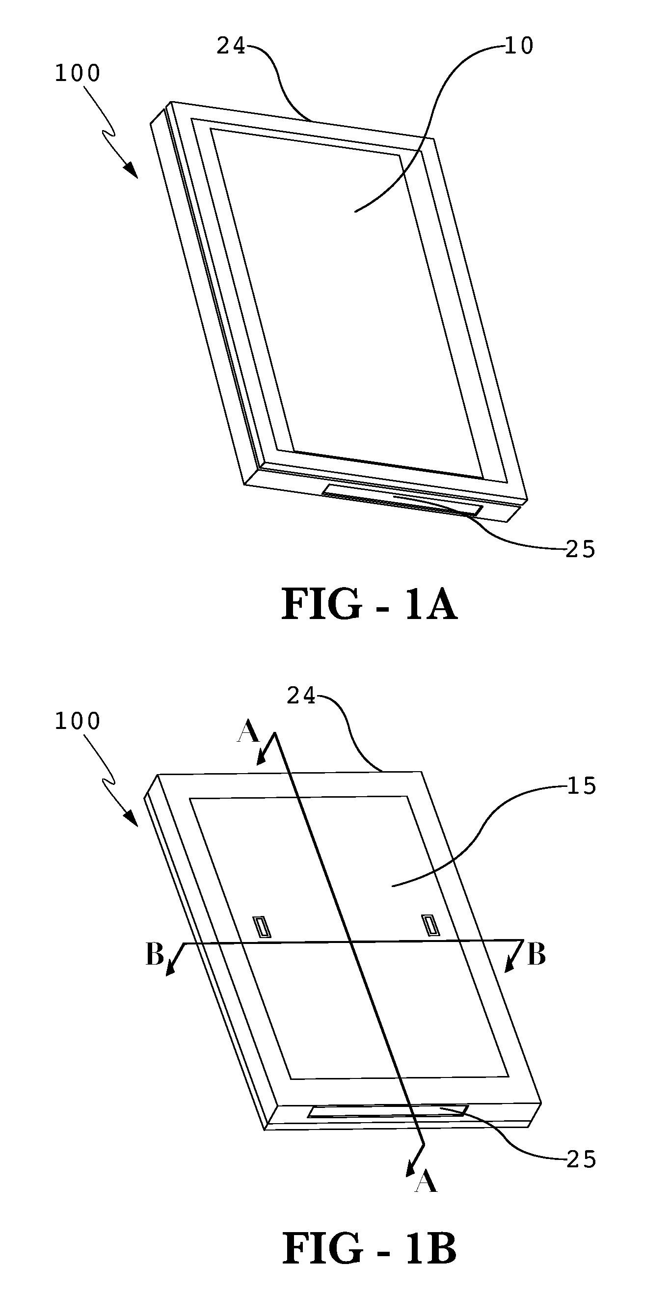
FIG. 1A provides a front perspective view of an exemplary embodiment of the electronic display 100. A transparent front plate 10 is placed on the front portion of the display to protect the internal components and allow the images produced by the display 100 to be seen. Some embodiments may use glass as the transparent front plate 10. Exemplary embodiments may use two pieces of glass laminated with index-matching optical adhesive. Some front plates 10 may provide other utility such as anti-reflection or polarizing functions. An inlet aperture 24 and exit aperture 25 may be provided in the housing so that the display 100 can accept ambient gas for cooling the display 100.
FIG. 1B provides a rear perspective view of an exemplary embodiment of the electronic display 100. A rear cover 15 may be used to provide access to the internal components of the display 100.
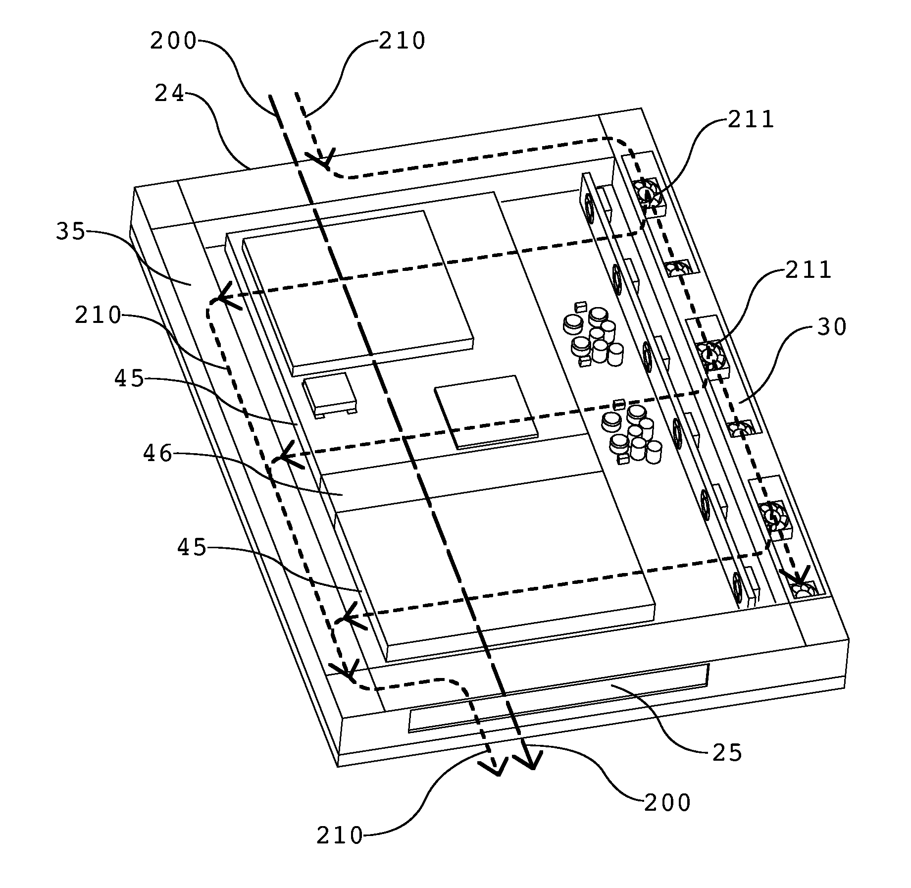
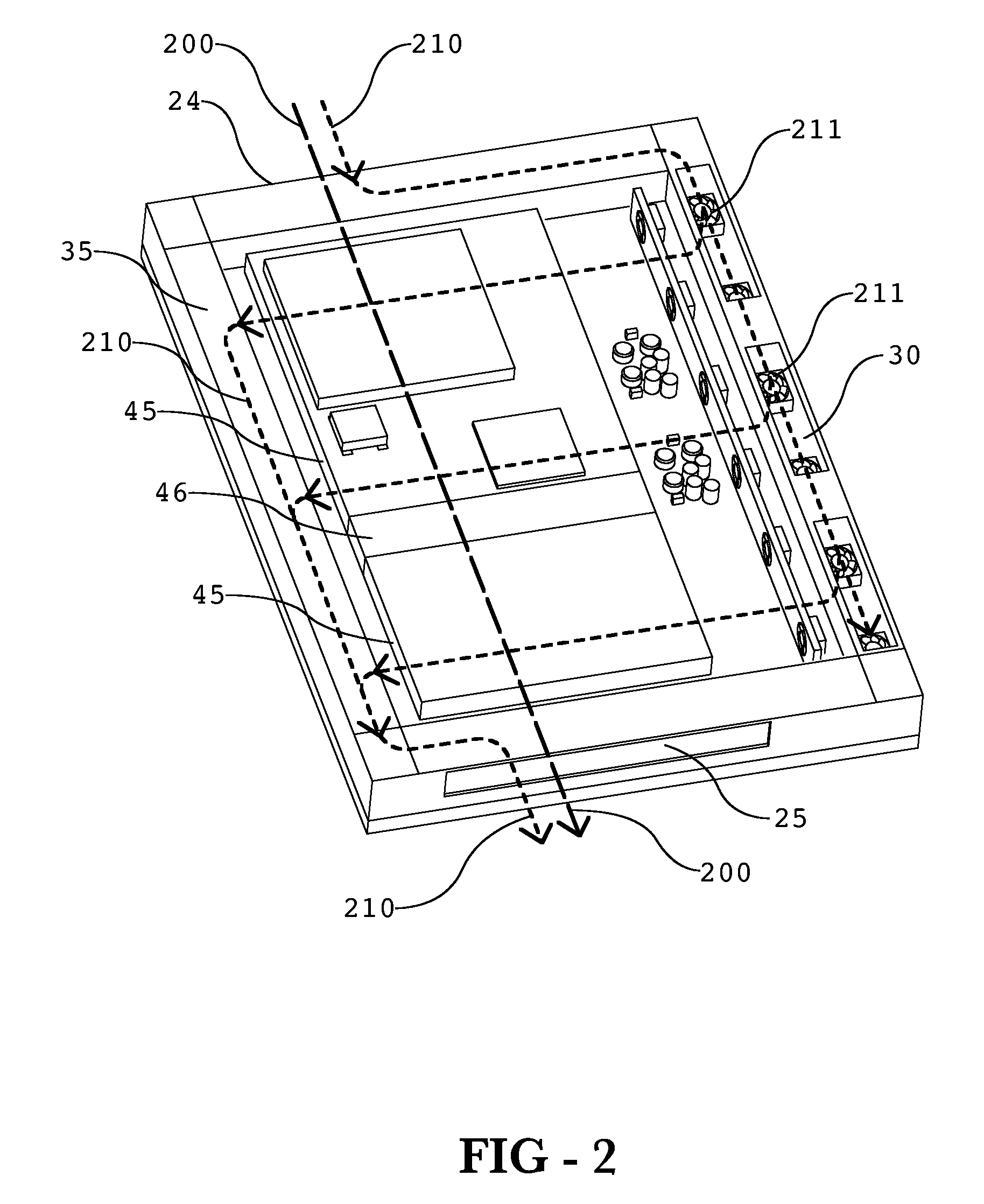
FIG. 2 provides a rear perspective view similar to that shown in FIG. 1B where the rear cover 15 has been removed. Ambient gas 200 may be ingested into the display through the inlet aperture 24 and pass through a heat exchanger 45 and exit the display through the exit aperture 25. The ambient gas 200 may be drawn into the display and forced through the heat exchanger 45 using heat exchanger fan assembly 46. An exemplary placement for the heat exchanger fan assembly 46 is discussed further below, but in many embodiments the fan assembly 46 can be placed near the inlet aperture 24 and/or exit aperture 25 and may or may not be placed within the heat exchanger 45 (as shown in FIG. 2).
Optionally, ambient gas 210 may also be ingested into the display through inlet aperture 24 (or a separate inlet aperture). Ambient gas 210 may then be directed through a first manifold 30 which travels along the edge of the display. The first manifold 30 accepts the single larger inlet flow of ambient gas 210 and distributes it into a plurality of smaller flows (channels 60) across the display. A second manifold 35 may be placed along the opposite edge of the display as the first manifold 30. The second manifold 35 accepts the plurality of smaller flows (channels 60) and combines them into a single flow and exhausts it out of the exit aperture 25 (or a separate exit aperture). In this embodiment, a manifold fan assembly 211 is used to draw the ambient gas 210 into the inlet aperture 24 and force the ambient gas 210 across the display. For this particular embodiment, the manifold fan assembly 211 is placed within the first manifold 30 and is used to draw the ambient gas 210 into the display as well as distribute the single flow into a plurality of smaller flows (channels 60). This is not required however, as some embodiments may place the manifold fan assembly 211 in the second manifold 35, or within both the first and second manifolds 30 and 35.
The first and second manifolds 30 and 35 may be placed along any opposing edges of the display. However, it is preferable that the first and second manifolds 30 and 35 are placed along the vertical edges of the display with the channels 60 travelling horizontally. Other embodiments may place the first and second manifolds 30 and 35 along the horizontal edges of the display with the channels 60 travelling vertically.
While both flows of ambient gas may be used in an exemplary embodiment, there is no requirement that they are both used. Some embodiments may use only ambient gas 200 or ambient gas 210. Also, if using both flows of ambient gas 200 and ambient gas 210 there is no requirement that they share the same inlet and exit apertures. Thus, there may be separate inlet and exit apertures for the two flows of ambient gas.
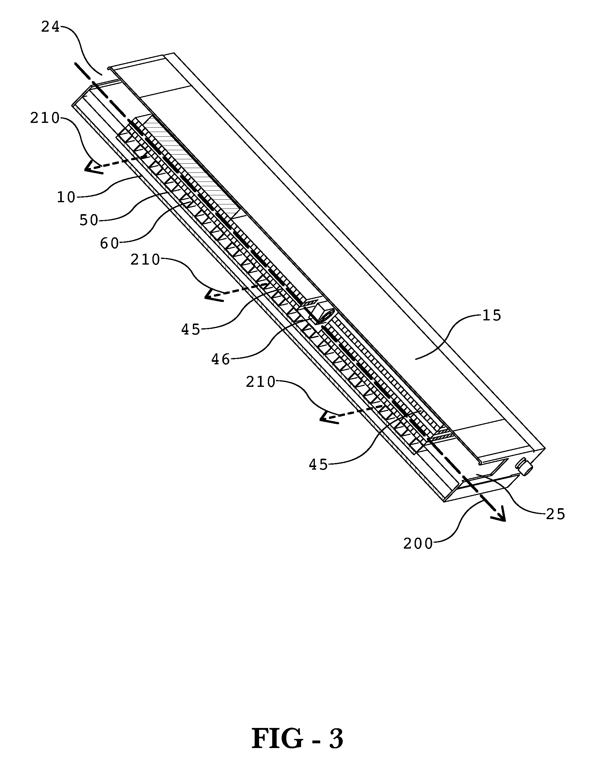
FIG. 3 provides a perspective sectional view along the A-A section line shown in FIG. 1B. Again, ambient gas 200 may be ingested into the display through the inlet aperture 24 and pass through a heat exchanger 45 and exit the display through the exit aperture 25. The ambient gas 200 may be drawn into the display and forced through the heat exchanger 45 using heat exchanger fan assembly 46. Obviously, the inlet aperture 24 may contain a filter or other coverings so that contaminates, insects, garbage, and/or water/fluids cannot easily be ingested into the display. However, an exemplary embodiment would not be damaged if the ambient gas 200 contained contaminates as they would only pass through the heat exchanger 45 which may not be susceptible to damage from particulate or contaminates. Exit aperture 25 may also contain some type of covering to ensure that contaminates and/or insects could not enter the display.
An electronic image assembly 50 may be placed behind the front plate 10. A plurality of channels 60 may be placed behind the electronic image assembly 50. Ambient gas 210 may be forced through the channels 60 after travelling through the first manifold 30 (not shown here). The flow of ambient gas 210 behind the electronic image assembly 50 may be used to remove any buildup of heat from the rear portion of the electronic image assembly 50. It may be preferable to have a thermally conductive surface/plate on the rear portion of the electronic image assembly 50 so that heat can easily transfer to this surface/plate and be removed by the ambient gas 210.
The channels 60 can take on any number of forms. Although shown in this embodiment with a square cross-section this is not required. Other embodiments may contain channels 60 with I-beam cross-sections, hollow square cross-sections, hollow rectangular cross-section, solid rectangular or solid square cross-sections, `T` cross-sections, `Z` cross-sections, a honeycomb cross-section, or any combination or mixture of these. The channels 60 are preferably thermally conductive and also preferably in thermal communication with the electronic image assembly 50. Thus, in a preferred embodiment, heat which accumulates on the rear portion of the electronic image assembly 50 may be transferred throughout the channels 60 and removed by ambient gas 210. Preferably, the channels 60 are metallic and even more preferably aluminum. Further, in an exemplary embodiment the channels 60 are in conductive thermal communication with the electronic image assembly 50.
FIG. 4 provides a perspective sectional view along the B-B section line shown in FIG. 1B. In this view, the path of the circulating gas 250 can also be observed. The space between the front plate 10 and the electronic image assembly 50 may define a front channel 251, through which the circulating gas 250 may travel in order to remove any accumulation of heat on the front surface of the electronic image assembly 50. The circulating gas 250 is preferably then directed into the heat exchanger 45 where heat may be transferred from the circulating gas 250 to the ambient gas 200. Upon exiting the heat exchanger 45, the circulating gas 250 may be re-directed into the front channel 251. In this way, the heat exchanger 45 and the front channel 251 are placed in gaseous communication with each other.
The circulating gas 250 may also be directed over various electronic components 7 so that heat may be transferred from the electronic components 7 to the circulating gas 250. The electronic components 7 could be any one of the following but not limited to: power modules, heat sinks, capacitors, motors, microprocessors, hard drives, AC/DC converters, transformers, or printed circuit boards.
Also shown in this sectional view is the path of the ambient gas 210 travelling down one of the channels 60 behind the electronic image assembly 50. In this embodiment, the ambient gas 210 is forced out of the first manifold 30, across the channels 60, and into the second manifold 35 by manifold fan assembly 211. In other words, each channel 60 preferably has an inlet which is in gaseous communication with the first manifold 30 as well as an exit which is in gaseous communication with the second manifold 35. As shown in this Figure, the paths of the ambient gas 210 and the circulating gas 250 may cross, but it is preferable to keep the two gases from mixing (as the ambient gas 210 may contain particulate or contaminates while the circulating gas 250 can remain substantially free of particulate and contaminates). It may be preferable to keep the circulating gas 250 from having particulate or contaminates because it travels in front of the electronic image assembly 50. Thus, to keep the image quality from being impaired, it may be desirable to keep the circulating gas 250 clean and prevent it from mixing with the ambient gas 210.
FIG. 5 provides a perspective sectional view of insert C shown in FIG. 4. As noted above, if practicing an embodiment which uses ambient gas 210 as well as the circulating gas 250, the pathways of the two gases may need to cross over one another and it may be desirable to prohibit them from mixing to prevent contamination of sensitive portions of the display. Here, cross through plate 500 allows the pathways of the two gases to cross over one another without letting them mix together. The cross through plate 500 in this embodiment contains a series of voids which pass through the plate. A first series of voids 550 passes through the cross through plate 500 and allows ambient gas 210 to travel from the first manifold 30 into the channels 60 which run behind the electronic image assembly 50. A second series of voids 525 pass through the cross through plate 500 in a direction substantially perpendicular to that of the first series of voids 550. The second series of voids 525 allows the circulating gas to exit the front channel 251, cross over the ambient gas 210, and continue towards the heat exchanger 45. In this embodiment, a circulating gas fan assembly 255 is used to draw the circulating gas 250 through the front channel 251 and through the heat exchanger 45. Much like the other fan assemblies shown and described here, the circulating gas fan assembly 255 could be placed anywhere within the display, including but not limited to the entrance/exit of the heat exchanger 45 or the entrance/exit of the front channel 251.
FIG. 6 provides a perspective sectional view of one embodiment of the cross through plate 500. In this embodiment, the cross through plate 500 is comprised of a plurality of hollow blocks 503 sandwiched between a top plate 501 and bottom plate 502 with sections of the plates 501 and 502 removed to correspond with the hollow sections of the blocks 503. A portion of the top plate 501 has been removed to show the detail of the hollow blocks 503, first series of voids 550, and second series of voids 525. The cross through plate 500 could take on any number of forms and could be constructed in a number of ways. Some other embodiments may use a solid plate where the first and second series of voids 550 and 525 are cut out of the solid plate. Other embodiments could use two sets of hollow blocks where the hollow sections are perpendicular to each other and the blocks are fastened together. Still other embodiments could use a design similar to those that are taught below for the heat exchanger 45, for example any type of cross-flow heat exchanger design could be used. Thus, an exemplary cross through plate 500 contains two gaseous pathways where the two pathways do not allow the gaseous matter to mix. Here, the first gas pathway would be 525 while the second gas pathway would be 550.
FIG. 7 provides an exploded perspective view of one exemplary embodiment of the heat exchanger 45 and fan assembly 46. In this view, the fan assembly 46 is shown removed from its mounted position within the fan housing 51. In this embodiment, the heat exchanger 45 is divided into two portions 47 and 48 where the fan housing 51 is used to provide a gaseous communication between the two portions 47 and 48. Here, the fan assembly 46 is placed between the two portions 47 and 48. While the fan assembly 46 can be placed anywhere so that it draws ambient gas 200 through the heat exchanger 45, it has been found that placing the fan assembly 46 between the two portions of the heat exchanger can provide a number of benefits. First, the volumetric flow rate of the ambient gas 200 through the heat exchanger is high, which results in better cooling capabilities for the heat exchanger 45. Second, the noise produced by the fan assembly 46 can be reduced because the surrounding portions 47 and 48 of the heat exchanger 45 essentially act as a muffler for the fan assembly 46.
In this embodiment, portion 48 is thinner and longer than portion 47. This was done in order to free up more space within the housing so that additional electronic components could fit within the housing (adjacent to portion 48). As shown, the fan housing 51 may be used to connect two portions of a heat exchanger which may be of different lengths. As shown, portion 48 of the heat exchanger is thinner than the fan housing 51. In an alternative embodiment, both portions 48 and 47 may be thinner than the fan assembly 46 such that a fan housing 51 may be used to provide a sealed gaseous communication between the two portions, even though they are both thinner than the fan assembly 51. This design may be preferable when it is desirable to create the largest possible heat exchanger 45 (for maximum cooling abilities) even though space is limited. This is of course not required, and other embodiments may have portions which are of equal width and length. Also, although this embodiment uses the fan assembly 46 to drive the ambient gas 200, other embodiments could use a fan assembly placed within the heat exchanger to drive the circulating gas 250 instead and drive the ambient gas 200 with another fan assembly (possibly placed within the heat exchanger or located at the entrance/exit of the heat exchanger). Some exemplary embodiments may place fans within the heat exchanger 45 to drive both the ambient gas 200 and circulating gas 250.
The ambient gas 200 travels through a first pathway (or plurality of pathways) of the heat exchanger 45 while the circulating gas 250 travels through a second pathway (or plurality of pathways) of the heat exchanger 45. Although not required, it is preferable that the circulating gas 250 and ambient gas 200 do not mix. This may prevent any contaminates and/or particulate that is present within the ambient gas 200 from harming the interior of the display. In a preferred embodiment, the heat exchanger 45 would be a cross-flow heat exchanger. However, many types of heat exchangers are known and can be used with any of the embodiments herein. The heat exchanger 45 may be a cross-flow, parallel flow, or counter-flow heat exchanger. In an exemplary embodiment, the heat exchanger 45 would be comprised of a plurality of stacked layers of thin plates. The plates may have a corrugated, honeycomb, or tubular design, where a plurality of channels/pathways/tubes travel down the plate length-wise. The plates may be stacked such that the directions of the pathways are alternated with each adjacent plate, so that each plate's pathways are substantially perpendicular to the pathways of the adjacent plates. Thus, ambient gas or circulating gas may enter an exemplary heat exchanger only through plates whose channels or pathways travel parallel to the path of the gas. Because the plates are alternated, the circulating gas and ambient gas may travel in plates which are adjacent to one another and heat may be transferred between the two gases without mixing the gases themselves (if the heat exchanger is adequately sealed, which is preferable but not required).
In an alternative design for a heat exchanger, an open channel may be placed in between a pair of corrugated, honeycomb, or tubular plates. The open channel may travel in a direction which is perpendicular to the pathways of the adjacent plates. This open channel may be created by running two strips of material or tape (esp. very high bond (VHB) tape) between two opposite edges of the plates in a direction that is perpendicular to the direction of the pathways in the adjacent plates. Thus, gas entering the heat exchanger in a first direction may travel through the open channel (parallel to the strips or tape). Gas which is entering in a second direction (substantially perpendicular to the first direction) would travel through the pathways of the adjacent plates).
Other types of cross-flow heat exchangers could include a plurality of tubes which contain the first gas and travel perpendicular to the path of the second gas. As the second gas flows over the tubes containing the first gas, heat is exchanged between the two gases. Obviously, there are many types of cross-flow heat exchangers and any type would work with the embodiments herein.
An exemplary heat exchanger may have plates where the sidewalls have a relatively low thermal resistance so that heat can easily be exchanged between the two gases. A number of materials can be used to create the heat exchanger. Preferably, the material used should be corrosion resistant, rot resistant, light weight, and inexpensive. Metals are typically used for heat exchangers because of their high thermal conductivity and would work with these embodiments. However, it has been discovered that plastics and composites can also satisfy the thermal conditions for electronic displays. An exemplary embodiment would utilize polypropylene as the material for constructing the plates for the heat exchanger. It has been found that although polypropylene may seem like a poor thermal conductor, the large amount of surface area relative to a small sidewall thickness, results in an overall thermal resistance that is low. Thus, an exemplary heat exchanger would be made of plastic and would thus produce a display assembly that is thin and lightweight. Specifically, corrugated plastic may be used for each plate layer where they are stacked together in alternating fashion (i.e. each adjacent plate has channels which travel in a direction perpendicular to the surrounding plates).
FIG. 8 provides a perspective sectional view of another embodiment which uses a flow of circulating gas 350 through the backlight cavity of a liquid crystal display (LCD) 300. In this embodiment, a LCD 300 and an associated backlight 320 are used as the electronic image assembly. A backlight wall 330 may enclose the area between the LCD 300 and the backlight 320 in order to create a backlight cavity. Typically, the backlight cavity is closed to prevent contaminates/particulate from entering the backlight cavity and disrupting the optical/electrical functions of the backlight 320. However, as discussed above the exemplary embodiments may use a clean gaseous matter for the circulating gases which could now be used to ventilate the backlight cavity in order to cool the backlight 320 and even the rear portion of the LCD 300. An opening 340 can be placed in the backlight wall 330 to allow circulating gas 350 to flow through the backlight cavity. A fan assembly 360 may be used to draw the circulating gas 350 through the backlight cavity. In an exemplary embodiment there would be an opening on the opposing backlight wall (on the opposite side of the display as shown in this figure) so that circulating gas 350 could easily flow through the backlight cavity. In this way, the backlight cavity is placed in gaseous communication with the heat exchanger 45.
FIG. 9 provides a perspective sectional view of an exemplary embodiment which uses a flow of circulating gas 350 through the backlight cavity in addition to the flow of circulating gas 250 through the front channel 251 (the area defined between the LCD 300 and front plate 10). Circulating fan assembly 255 may be placed so that it can draw circulating gas 350 through the backlight cavity as well as circulating gas 250 through the front channel 251. As discussed above, the circulating gases 250 and 350 are preferably forced through the heat exchanger 45 (not shown in this figure) so that they may be cooled by the ambient gas 200 (also not shown in this figure). In this way, both the front channel 251 and the backlight cavity are placed in gaseous communication with the heat exchanger 45.
Also shown in FIG. 9 is the optional additional flow of ambient gas 210 which may travel immediately behind the electronic image assembly (in this embodiment backlight 320). Once travelling through the first manifold 30, the ambient gas 210 may pass through the channels 60 in order to remove heat from the backlight 320 and even the channels 60 themselves (if they are thermally conductive). The manifold fan assembly 211 may be used to draw the ambient gas 210 into the first manifold 30 and through the channels 60. Again, the cross though plate 500 may be used to allow the circulating gases 350 and 250 to cross paths with the ambient gas 210 without letting the two gases mix.
In an exemplary embodiment, the backlight 320 would contain a plurality of LEDs mounted on a thermally conductive substrate (preferably a metal core PCB). On the surface of the thermally conductive substrate which faces the channels 60 there may be a thermally conductive plate which may be in thermal communication with the channels 60. In an exemplary embodiment, the thermally conductive plate would be metallic and more preferably aluminum and the thermal communication between the channels 60 and the backlight 320 would be conductive thermal communication.
As noted above, many electronic image assemblies (especially LEDs, LCDs, and OLEDs) may have performance properties which vary depending on temperature.
When `hot spots` are present within an image assembly, these hot spots can result in irregularities in the resulting image which might be visible to the end user. Thus, with the embodiments described herein, the heat which may be generated by the image assembly (sometimes containing a backlight assembly) can be distributed (somewhat evenly) throughout the channels 60 and thermally-conductive surfaces to remove hot spots and cool the backlight and/or electronic image assembly.
The circulating gases 250 and 350, ambient gas 200, and optional ambient gas 210 can be any number of gaseous matters. In some embodiments, air may be used as the gas for all. As well known by those of ordinary skill in the art, air typically contains some amount of water vapor. It should be noted that the use of the term `gas` herein does not designate pure gas and that it is specifically contemplated that any of the gaseous matters described herein may contain some amount of impurities including but not limited to water vapor. Preferably, because the circulating gases 250 and 350 may travel in front of the image assembly and backlight respectively, they should be substantially clear, so that they will not affect the appearance of the image to a viewer. The circulating gases 250 and 350 should also preferably be substantially free of contaminates and/or particulate in order to prevent an adverse effect on the image quality and/or damage to the internal electronic components. It may sometimes be preferable to keep ambient gases 200 and 210 from having contaminates as well. Filters may be used to help reduce the particulate within ambient gases 200 and 210. Filters could be placed near the inlet aperture 24 so that ambient gases 200 and/or 210 could be drawn through the filter. However, in an exemplary embodiment the display may be designed so that contaminates could be present within the ambient gases 200 and 210 but this will not harm the display. In these embodiments, the heat exchanger 45, manifolds 30 and 35, channels 60, and any other pathway for ambient or circulating gas should be properly sealed so that any contaminates in the ambient gas would not enter sensitive portions of the display. Thus, in these exemplary embodiments, ambient air may be ingested for the ambient gases 200 and 210, even if the ambient air contains contaminates or particulate. This can be particularly beneficial when the display is used in outdoor environments or indoor environments where contaminates are present in the ambient air.
The cooling system may run continuously. However, if desired, temperature sensing devices (not shown) may be incorporated within the electronic display to detect when temperatures have reached a predetermined threshold value. In such a case, the various cooling fans may be selectively engaged when the temperature in the display reaches a predetermined value. Predetermined thresholds may be selected and the system may be configured to advantageously keep the display within an acceptable temperature range. Typical thermostat assemblies can be used to accomplish this task. Thermocouples may be used as the temperature sensing devices.
It is to be understood that the spirit and scope of the disclosed embodiments provides for the cooling of many types of electronic image assemblies. As used herein, the term `electronic image assembly` is any electronic assembly for creating an image. At this time this, these are LCD (all types), light emitting diode (LED), organic light emitting diode (OLED), field emitting display (FED), light emitting polymer (LEP), organic electro luminescence (OEL), plasma displays, and any thin/flat panel electronic image assembly. Furthermore, embodiments may be used with displays of other types including those not yet discovered. In particular, it is contemplated that the system may be well suited for use with full color, flat panel OLED displays. Exemplary embodiments may also utilize large (55 inches or more) LED backlit, high definition liquid crystal displays (LCD). While the embodiments described herein are well suited for outdoor environments, they may also be appropriate for indoor applications (e.g., factory/industrial environments, spas, locker rooms) where thermal stability of the display may be a concern.
As is well known in the art, electronic displays can be oriented in a portrait manner or landscape manner and either can be used with the embodiments herein.
Having shown and described preferred embodiments, those skilled in the art will realize that many variations and modifications may be made to affect the described embodiments and still be within the scope of the claimed invention. Additionally, many of the elements indicated above may be altered or replaced by different elements which will provide the same result and fall within the spirit of the claimed invention. It is the intention, therefore, to limit the invention only as indicated by the scope of the claims.
* * * * *
D00000
D00001
D00002
D00003
D00004
D00005
D00006
D00007
D00008
D00009
XML
uspto.report is an independent third-party trademark research tool that is not affiliated, endorsed, or sponsored by the United States Patent and Trademark Office (USPTO) or any other governmental organization. The information provided by uspto.report is based on publicly available data at the time of writing and is intended for informational purposes only.
While we strive to provide accurate and up-to-date information, we do not guarantee the accuracy, completeness, reliability, or suitability of the information displayed on this site. The use of this site is at your own risk. Any reliance you place on such information is therefore strictly at your own risk.
All official trademark data, including owner information, should be verified by visiting the official USPTO website at www.uspto.gov. This site is not intended to replace professional legal advice and should not be used as a substitute for consulting with a legal professional who is knowledgeable about trademark law.