Electrochemical energy storage devices and manufacturing methods
Rawal , et al.
U.S. patent number 10,312,028 [Application Number 14/749,785] was granted by the patent office on 2019-06-04 for electrochemical energy storage devices and manufacturing methods. This patent grant is currently assigned to AVX Corporation. The grantee listed for this patent is AVX Corporation. Invention is credited to Carl L. Eggerding, Bob Knopsnyder, Bharat Rawal.


View All Diagrams
| United States Patent | 10,312,028 |
| Rawal , et al. | June 4, 2019 |
Electrochemical energy storage devices and manufacturing methods
Abstract
An ultra-thin electrochemical energy storage device is provided which utilizes electrode material with multi-layer current collectors and with an organic electrolyte between the electrodes. Multiple cells may be positioned in a plurality of stacks and all of the cells may be in series, parallel or some combination thereof. The energy storage device can be constructed at less than 0.5 millimeters thick and exhibit very low ESR and higher temperature range capabilities.
| Inventors: | Rawal; Bharat (Surfside Beach, SC), Eggerding; Carl L. (Greenville, SC), Knopsnyder; Bob (Simpsonville, SC) | ||||||||||
|---|---|---|---|---|---|---|---|---|---|---|---|
| Applicant: |
|
||||||||||
| Assignee: | AVX Corporation (Fountain Inn,
SC) |
||||||||||
| Family ID: | 54839986 | ||||||||||
| Appl. No.: | 14/749,785 | ||||||||||
| Filed: | June 25, 2015 |
Prior Publication Data
| Document Identifier | Publication Date | |
|---|---|---|
| US 20150380175 A1 | Dec 31, 2015 | |
Related U.S. Patent Documents
| Application Number | Filing Date | Patent Number | Issue Date | ||
|---|---|---|---|---|---|
| 62018739 | Jun 30, 2014 | ||||
| Current U.S. Class: | 1/1 |
| Current CPC Class: | H01G 11/80 (20130101); H01G 11/72 (20130101); H01G 11/82 (20130101); H01G 11/84 (20130101); H01G 11/60 (20130101); H01G 11/12 (20130101); H01G 11/74 (20130101); H01G 11/76 (20130101); Y02E 60/13 (20130101) |
| Current International Class: | H01G 11/60 (20130101); H01G 11/84 (20130101); H01G 11/76 (20130101); H01G 11/12 (20130101); H01G 11/74 (20130101); H01G 11/80 (20130101); H01G 11/72 (20130101); H01G 11/82 (20130101) |
References Cited [Referenced By]
U.S. Patent Documents
| 3652902 | March 1972 | Hart et al. |
| 4267565 | May 1981 | Puppolo et al. |
| 4267566 | May 1981 | Moresi, Jr. |
| 4766523 | August 1988 | Mori |
| 5079674 | January 1992 | Malaspina |
| 5150283 | September 1992 | Yoshida et al. |
| 5279623 | January 1994 | Watanabe et al. |
| 5381303 | January 1995 | Yoshida et al. |
| 5426561 | June 1995 | Yen et al. |
| 5445856 | August 1995 | Charloner-Gill |
| 5591540 | January 1997 | Louie et al. |
| 5621607 | April 1997 | Farahmandi |
| 5777428 | July 1998 | Farahmandi et al. |
| 5973913 | October 1999 | McEwen et al. |
| 6059847 | May 2000 | Farahmandi et al. |
| 6064561 | May 2000 | Harada et al. |
| 6064562 | May 2000 | Okamura |
| 6187061 | February 2001 | Amatucci et al. |
| 6198620 | March 2001 | Wei et al. |
| 6212061 | April 2001 | Irwin et al. |
| 6304426 | October 2001 | Wei et al. |
| 6335858 | January 2002 | Vasechkin et al. |
| 6349027 | February 2002 | Suhara et al. |
| 6352565 | March 2002 | Suhara et al. |
| 6364915 | April 2002 | Chapman-Irwin et al. |
| 6379402 | April 2002 | Suhara et al. |
| 6414837 | July 2002 | Sato et al. |
| 6424517 | July 2002 | Ikeda et al. |
| 6430031 | August 2002 | Dispennette et al. |
| 6447555 | September 2002 | Okamura et al. |
| 6449139 | September 2002 | Farahmandi et al. |
| 6466429 | October 2002 | Volkovich et al. |
| 6493210 | December 2002 | Nonaka et al. |
| 6552895 | April 2003 | Vassallo et al. |
| 6576365 | June 2003 | Meitav |
| 6627343 | September 2003 | Kim et al. |
| 6628504 | September 2003 | Volkovich et al. |
| 6631072 | October 2003 | Paul et al. |
| 6726732 | April 2004 | Kim et al. |
| 6728095 | April 2004 | Suhara et al. |
| 6743544 | June 2004 | Kim et al. |
| 6751084 | June 2004 | Nakazawa et al. |
| 6830594 | December 2004 | Shinozaki et al. |
| 6842330 | January 2005 | Farahmandi et al. |
| 6847517 | January 2005 | Iwaida et al. |
| 6898067 | May 2005 | Hiratsuka et al. |
| 6944010 | September 2005 | Paul et al. |
| 7019960 | March 2006 | Okamura et al. |
| 7057879 | June 2006 | Iwaida et al. |
| 7061750 | June 2006 | Oyama et al. |
| 7090706 | August 2006 | Farahmandi et al. |
| 7095603 | August 2006 | Mahon et al. |
| 7116545 | October 2006 | Farahmandi et al. |
| 7154738 | December 2006 | Oyama et al. |
| 7227737 | June 2007 | Mitchell et al. |
| 7233482 | June 2007 | James et al. |
| 7256981 | August 2007 | Kosuda et al. |
| 7273597 | September 2007 | Takeuchi et al. |
| 7310219 | December 2007 | Kosuda et al. |
| 7382600 | June 2008 | Paul et al. |
| 7407520 | August 2008 | Farahmandi et al. |
| 7486497 | February 2009 | Kobayashi et al. |
| 7554790 | June 2009 | James et al. |
| 7570478 | August 2009 | Terada et al. |
| 7623339 | November 2009 | Takahashi et al. |
| 7811337 | October 2010 | Zhong et al. |
| 7830646 | November 2010 | Eilertsen |
| 7864508 | January 2011 | Fukumine |
| 7920371 | April 2011 | Mitchell et al. |
| 7939600 | May 2011 | Mori et al. |
| 7948738 | May 2011 | Shimamoto et al. |
| 8077444 | December 2011 | Osawa |
| 8098481 | January 2012 | Zong et al. |
| 8098482 | January 2012 | Clelland et al. |
| 8098483 | January 2012 | Eilertsen |
| 8223473 | July 2012 | Dreissig et al. |
| 8351182 | January 2013 | Yamada et al. |
| 8472164 | June 2013 | Kim |
| 8497225 | July 2013 | Zhamu et al. |
| 8537525 | September 2013 | Yamazaki et al. |
| 8591757 | November 2013 | Ohishi et al. |
| 8652687 | February 2014 | Zhamu et al. |
| 8749953 | June 2014 | Momo et al. |
| 8760851 | June 2014 | Signorelli et al. |
| 8848338 | September 2014 | Norieda et al. |
| 8932750 | January 2015 | Cooley et al. |
| 8947856 | February 2015 | Wang et al. |
| 8964357 | February 2015 | Tamachi et al. |
| 8982535 | March 2015 | Soulliere et al. |
| 9209434 | December 2015 | Epstein |
| 9478366 | October 2016 | Yokouchi et al. |
| 9576746 | February 2017 | Ueno et al. |
| 9679703 | June 2017 | Bendale et al. |
| 9818552 | November 2017 | Lane et al. |
| 2002/0138958 | October 2002 | Nonaka et al. |
| 2002/0164441 | November 2002 | Amine et al. |
| 2003/0007316 | January 2003 | Takasugi |
| 2005/0211136 | September 2005 | Drummond |
| 2005/0231891 | October 2005 | Harvey |
| 2006/0087799 | April 2006 | Kosuda |
| 2006/0092596 | May 2006 | Otsuki et al. |
| 2008/0003166 | January 2008 | Maletin et al. |
| 2008/0013253 | January 2008 | Thrap et al. |
| 2008/0016664 | January 2008 | Mitchell et al. |
| 2008/0259525 | October 2008 | Guillet et al. |
| 2009/0244812 | October 2009 | Rawal |
| 2009/0279230 | November 2009 | Eilertsen et al. |
| 2010/0266878 | October 2010 | Eilertsen |
| 2012/0044614 | February 2012 | Hommo et al. |
| 2012/0183886 | July 2012 | Zhong et al. |
| 2013/0026978 | January 2013 | Cooley et al. |
| 2013/0059195 | March 2013 | Kuriki |
| 2013/0120906 | May 2013 | Soulliere et al. |
| 2013/0280569 | October 2013 | Mori et al. |
| 2013/0323585 | December 2013 | Inoue et al. |
| 2014/0029165 | January 2014 | Takahashi et al. |
| 2014/0035540 | February 2014 | Ehrenberg |
| 2014/0042988 | February 2014 | Kuttipillai |
| 2014/0065447 | March 2014 | Liu |
| 2014/0098465 | April 2014 | Bendale et al. |
| 2014/0139972 | May 2014 | Yokoshima |
| 2014/0377668 | December 2014 | Abe et al. |
| 2015/0207114 | July 2015 | Khakhalev et al. |
| 2016/0254104 | September 2016 | Eilertsen |
| 2017/0338054 | November 2017 | Knopsnyder et al. |
| 2017/0338055 | November 2017 | Knopsnyder et al. |
| 2017/0338059 | November 2017 | Knopsnyder et al. |
| 2017/0338061 | November 2017 | Knopsnyder et al. |
| 2017/0338669 | November 2017 | Hansen |
| 2018/0144878 | May 2018 | Ritter et al. |
| 203406180 | Jan 2014 | CN | |||
| 203596278 | May 2014 | CN | |||
| 0 938 109 | Aug 1999 | EP | |||
| 1256966 | Nov 2002 | EP | |||
| 2 044 000 | Aug 1983 | GB | |||
| H 06342739 | Dec 1994 | JP | |||
| H 09270370 | Oct 1997 | JP | |||
| H 09298129 | Nov 1997 | JP | |||
| 2004253562 | Sep 2004 | JP | |||
| 2012069408 | Apr 2012 | JP | |||
| 100383511 | May 2003 | KR | |||
| 100516108 | Sep 2005 | KR | |||
| WO0137295 | May 2001 | WO | |||
Other References
|
Product Information on TIMREX.RTM. Graphite and ENSACO.TM. Carbon Black from TIMCAL Ltd., 2004, 24 pages. cited by applicant. |
Primary Examiner: Ha; Nguyen T
Attorney, Agent or Firm: Dority & Manning, P.A.
Parent Case Text
PRIORITY CLAIM
This application claims the benefit of previously filed U.S. Provisional Patent Application entitled "ORGANIC ELECTROLYTE CAPACITORS," assigned U.S. Ser. No. 62/018,739, filed Jun. 30, 2014, and which is incorporated herein by reference for all purposes.
Claims
What is claimed is:
1. An ultra-thin electrochemical energy storage device, comprising: a pair of respective internal electrodes with electrolyte; a separator layer between said respective electrodes; a pair of respective current collectors, with one each of said current collectors respectively outside each of said electrodes; and a case surrounding said current collectors, and having a respective pair of terminals connected respectively with said current collectors; wherein the contents of said case have a thickness down to less than 0.5 millimeters; and wherein said device has a resistivity of no more than about 1.5 .OMEGA.cm.sup.2 of electrode area.
2. An ultra-thin electrochemical energy storage device as in claim 1, wherein said case has a moisture content of no more than about 10 ppm.
3. An ultra-thin electrochemical energy storage device as in claim 1, wherein said electrolyte comprises an organic electrolyte.
4. An ultra-thin electrochemical energy storage device as in claim 1, wherein said electrolyte includes at least some of propylene carbonate.
5. An ultra-thin electrochemical energy storage device as in claim 1, wherein: said device has a temperature operational range rating of -40.degree. to 70.degree. C.
6. An ultra-thin electrochemical energy storage device as in claim 1, further comprising a plurality of said devices arranged as multiple cells positioned in a plurality of stacks configured in one of series or parallel connections, or combinations thereof.
7. An ultra-thin electrochemical energy storage device as in claim 1, wherein: said device includes a plurality of said pair of internal electrodes, separator layer, and said pair of current collectors surrounded by said case; and said case has a thickness of from 0.5 millimeters to 5.0 millimeters.
8. An ultra-thin electrochemical energy storage device as in claim 1, wherein: said electrolyte comprises an organic electrolyte; and said device comprises an electrochemical double layer (ECDL) capacitor having a capacitance density of at least about 10 Farads per cc of active electrode volume.
9. An ultra-thin electrochemical energy storage device as in claim 8, wherein: said electrolyte has a boiling point over 200.degree. C.; said case further includes thermally stable sealant materials; and said capacitor has a temperature operational half-voltage range rating of up to 90.degree. C.
10. An ultra-thin electrochemical energy storage device as in claim 8, wherein: said organic electrolyte includes at least some of propylene carbonate; and said case has dimensions of about 50 mm long.times.40 mm wide.times.0.5 mm thick, and maintains dimensional stability at up to about 105.degree. C. storage temperature, while also maintaining very low ESR of down to about 150 m.OMEGA..
11. An ultra-thin, ultra-low ESR supercapacitor, comprising: a pair of respective internal electrodes with organic electrolyte; an ultra-thin separator layer between said respective electrodes; a pair of respective multi-layer current collectors, with one each of said current collectors respectively outside each of said electrodes; and a case surrounding said current collectors, and having a respective pair of terminals connected respectively with said current collectors; wherein the contents of said case have a thickness down to less than 0.5 millimeters, and a moisture content of no more than about 10 ppm, and said supercapacitor has a resistivity of no more than about 1.5 .OMEGA.cm.sup.2 of electrode area, capacitance density of at least about 10 Farads per cc of active electrode volume, and a temperature operational range rating of -40.degree. to 70.degree. C.
12. A supercapacitor as in claim 11, wherein said supercapacitor comprises a carbon double layer capacitor with a voltage rating of 4.2 volts, and a temperature operational half-voltage range rating of -40.degree. to 90.degree. C.
13. A supercapacitor as in claim 11, wherein said organic electrolyte includes at least some of propylene carbonate.
14. A supercapacitor as in claim 13, wherein said case has dimensions of about 50 mm long.times.40 mm wide.times.0.5 mm thick, and maintains dimensional stability at up to about 105.degree. C. storage temperature, while also maintaining very low ESR of down to about 150 m.OMEGA..
15. A supercapacitor as in claim 11, further comprising a plurality of said supercapacitors arranged as multiple cells positioned in a plurality of stacks.
16. A supercapacitor as in claim 15, wherein said stacks of multiple cells are arranged in one of series or parallel connections, or combinations thereof.
17. A supercapacitor as in claim 11, wherein: said device includes a plurality of said pair of internal electrodes, separator layer, and said pair of current collectors surrounded by said case; and said case has a thickness of from 0.5 millimeters to 5.0 millimeters.
18. A supercapacitor as in claim 11, wherein: said electrolyte has a boiling point over 200.degree. C.; said case further includes thermally stable sealant materials; and said supercapacitor has a temperature operational half-voltage range rating of up to 90.degree. C.
19. Methodology for manufacturing an ultra-thin electrochemical energy storage device, comprising: providing a pair of respective internal electrodes with electrolyte, and with a separator layer between such respective electrodes; providing a pair of respective current collectors, with one each of such current collectors respectively outside each of such electrodes; and surrounding such current collectors with a case having a respective pair of terminals connected respectively with such current collectors; wherein the contents of such case have a thickness down to less than 0.5 millimeters; and wherein said device has a resistivity of no more than about 1.5 .OMEGA.cm.sup.2 of electrode area.
20. Methodology as in claim 19, wherein said methodology is performed in a controlled environment having a moisture content of no more than about 10 ppm.
21. Methodology as in claim 19, wherein said electrolyte comprises an organic electrolyte.
22. Methodology as in claim 19, wherein said electrolyte includes at least some of propylene carbonate.
23. Methodology as in claim 19, wherein: said device has a temperature operational range rating of -40.degree. to 70.degree. C.
24. Methodology as in claim 19, further comprising arranging a plurality of said devices as multiple cells positioned in a plurality of stacks configured in one of series or parallel connections, or combinations thereof, for selectively achieving desired capacitance and/or operational voltage levels.
25. Methodology as in claim 19, wherein: said device includes a plurality of said pair of internal electrodes, separator layer, and said pair of current collectors surrounded by said case; and said case has a thickness of from 0.5 millimeters to 5.0 millimeters.
26. Methodology as in claim 19, wherein: said electrolyte comprises an organic electrolyte; and said device comprises an electrochemical double layer (ECDL) capacitor having a capacitance density of at least about 10 Farads per cc of active electrode volume.
27. Methodology as in claim 26, wherein: said electrolyte has a boiling point over 200.degree. C.; said case further includes thermally stable sealant materials; and said capacitor has a temperature operational half-voltage range rating of up to 90.degree. C.
28. Methodology as in claim 26, wherein: said organic electrolyte includes at least some of propylene carbonate; and said case has dimensions of about 50 mm long.times.40 mm wide.times.0.5 mm thick, and maintains dimensional stability at up to about 105.degree. C. storage temperature, while also maintaining very low ESR of down to about 150 m.OMEGA..
29. Methodology for making an ultra-thin, ultra-low ESR supercapacitor, comprising: providing a pair of respective internal electrodes with organic electrolyte, and with an ultra-thin separator layer between such respective electrodes; providing a pair of respective multi-layer current collectors, with one each of such current collectors respectively outside each of such electrodes; and surrounding such current collectors with a case having a respective pair of terminals connected respectively with such current collectors; wherein the contents of said case have a thickness down to less than 0.5 millimeters, and said methodology is performed in a controlled environment having a moisture content of no more than about 10 ppm, and said supercapacitor has a resistivity of no more than about 1.5 .OMEGA.cm.sup.2 of electrode area, capacitance density of at least about 10 Farads per cc of active electrode volume, and a temperature operational range rating of -40.degree. to 70.degree. C.
30. Methodology as in claim 29, wherein said supercapacitor comprises a carbon double layer capacitor with a voltage rating of 4.2 volts, a temperature operational half-voltage range rating of -40.degree. to 90.degree. C.
31. Methodology as in claim 29, wherein said organic electrolyte includes at least some of propylene carbonate.
32. Methodology as in claim 31, wherein said case has dimensions of about 50 mm long.times.40 mm wide.times.0.5 mm thick, and maintains dimensional stability at up to about 105.degree. C. storage temperature, while also maintaining very low ESR of down to about 150 m.OMEGA..
33. Methodology as in claim 29, further comprising a plurality of said supercapacitors arranged as multiple cells positioned in a plurality of stacks, for selectively achieving desired capacitance and/or operational voltage levels.
34. Methodology as in claim 33, wherein said stacks of multiple cells are arranged in one of series or parallel connections, or combinations thereof, for achieving hybrid packs of a battery or batteries combined with a capacitor or capacitors in a single integrated product.
35. Methodology as in claim 29, wherein: said device includes a plurality of said pair of internal electrodes, separator layer, and said pair of current collectors surrounded by said case; and said case has a thickness of from 0.5 millimeters to 5.0 millimeters.
36. Methodology as in claim 29, wherein: said electrolyte has a boiling point over 200.degree. C.; said case further includes thermally stable sealant materials; and said supercapacitor has a temperature operational half-voltage range rating of up to 90.degree. C.
Description
FIELD OF THE SUBJECT MATTER
The presently disclosed technology generally relates to electrochemical systems for storage and release of electrical energy and corresponding methodologies. More particularly, the presently disclosed technology relates to construction of organic-based electrolyte capacitor devices having very low equivalent series resistance (ESR) (and corresponding low resistivity) and elevated temperature operational capabilities, together with an ultra-thin construction, for providing specialized supercapacitor energy storage device performance.
BACKGROUND OF THE SUBJECT MATTER
The presently disclosed subject matter generally relates to electrochemical energy storage devices and manufacturing methods. In particular, the presently disclosed subject matter relates to electrochemical systems for use in electronic circuits, for example, as capacitors and/or batteries. More particularly, the presently disclosed subject matter relates to electrochemical systems having an organic solution electrolyte material.
Further still, in part, the presently disclosed subject matter relates to improved designs for assembly of a plurality of single cells of an electrochemical system. More particularly, individual cells may be connected individually to each other to form a stack (within a single case or plural cases), with stacks connected together to form an assembly. Further, the presently disclosed subject matter is more versatile for achieving inter-cell or inter-stack connections in series, parallel, or combinations thereof and for achieving hybrid packs of a battery or batteries combined with a capacitor or capacitors in a single integrated product.
As various electronic devices become more portable and provide more functionality, corresponding advances have been needed in the features and components of such devices that enable such portability. Frequently the limiting factor in both size and functionality of an electronic apparatus is the size and weight of its component parts and in particular, the size and weight of associated energy storage components. The general push towards miniaturization of electronics has also resulted in the integration of various components into a single device to save both room and weight.
Typical main energy sources used for portable electronics involve electrochemical batteries and/or electrochemical capacitors. As with other devices and components, one limiting aspect of energy storage components is the packaging of the electrochemical system, and the resulting size of the system.
From a performance perspective, additional aspects which impact or limit the use of particular constructions in particular applications are the range of temperatures within which the components are functional, as well as the equivalent series resistance (ESR) of the component relative to associated circuitry.
It is, therefore, desirable to provide an ultra-thin (ultra-low profile) energy storage component that may comprise an electrochemical capacitor using an organic electrolyte.
It is also desirable to provide such an electrochemical energy storage component useful for a single electronic device but wherein the cells are in series or parallel or a combination thereof by virtue of the component's construction.
Furthermore, it is desirable to provide such a device having improved very low ESR (and corresponding very low resistivity) and having an expanded temperature range for useful operation.
While various implementations of capacitor devices and associated assemblies and construction methodologies therefor have been developed, no design has emerged that generally encompasses all of the desired characteristics as hereafter presented in accordance with the subject technology.
SUMMARY OF THE SUBJECT MATTER
The presently disclosed subject matter recognizes and addresses various of the foregoing limitations and drawbacks, and others, concerning both the designs of electrochemical energy storage components and methods of making the same. Thus, broadly speaking, an object of certain embodiments of the presently disclosed technology is to provide improved designs for certain capacitor components and component assemblies associated with organic electrolyte-based capacitors. Other objects, broadly speaking relate to providing an improved ultra-thin electrochemical energy storage component comprising, that are connected in series, parallel or some combination thereof, in addition to improved methods of making such components.
It is, therefore, a principle object of the presently disclosed subject matter to provide an improved electrochemical capacitor
Another more particular object of the presently disclosed subject matter is to provide an electrochemical capacitor device with a very low (or ultra-low) equivalent series resistance (ESR) (and corresponding very low resistivity).
It is still a further object of the presently disclosed subject matter to provide an ultra-thin electrochemical capacitor device. In such context, it is a more particular object of the presently disclosed subject matter to provide an electrochemical energy storage component which by virtue of its construction facilitates placement of multiple connected cells in series, parallel or a combination thereof for varying capacitance and/or voltage
It is a further object of the presently disclosed subject matter to provide an ultra-thin electrochemical energy storage component that can be effectively manufactured.
It is a further object of the presently disclosed subject matter to provide an electrochemical energy storage component that effectively has an expanded temperature range of operation.
It is a further object of the presently disclosed subject matter to provide an improved electrochemical energy storage component that can be effectively manufactured with greatly reduced exposure to moisture during the manufacturing process, to yield a product with improved dimensional stability responsive to heat exposure.
It is a further object of the presently disclosed subject matter to provide an electrochemical energy storage component that effectively comprises a low ESR pulse super capacitor, or an improved low ESR electrochemical double layer capacitor (EDLC).
One exemplary embodiment in accordance with presently disclosed subject matter relates to an ultra-thin electrochemical energy storage device. Such a device preferably comprises a pair of respective internal electrodes with electrolyte; a separator layer between such respective electrodes; a pair of respective current collectors, with one each of such current collectors respectively outside each of such electrodes; and a case surrounding such current collectors, and having a respective pair of terminals connected respectively with such current collectors. Preferably, also the contents of such case have a thickness down to less than 0.5 millimeters.
In some variations of the foregoing, such case may have a moisture content of no more than about 10 ppm. In some such alternatives, such electrolyte may comprise an organic electrolyte, and in others such electrolyte comprises at least in part propylene carbonate.
In other alternative embodiments, such case may have a moisture content of no more than about 10 ppm, and such device may have a resistivity of no more than about 1.5 .OMEGA.cm.sup.2 of electrode area and a temperature operational range rating of -40.degree. to 70.degree. C.
In yet other configurations of exemplary embodiments, a plurality of such devices may be arranged as multiple cells positioned in a plurality of stacks configured in one of series or parallel connections, or combinations thereof.
In still other alternative configurations of exemplary embodiments, such device may include a plurality of such pair of internal electrodes, separator layer, and such pair of current collectors surrounded by such case, and such case may have a thickness of from 0.5 millimeters to 5.0 millimeters.
For other presently disclosed exemplary ultra-thin electrochemical energy storage device embodiments, such electrolyte may comprise an organic electrolyte; and such device may comprise an electrochemical double layer (ECDL) capacitor having a capacitance density of at least about 10 Farads per cc of active electrode volume. In still another alternative embodiment of such a presently disclosed ultra-thin electrochemical energy storage device, such electrolyte may have a boiling point over 200.degree. C.; such case may further include thermally stable sealant materials; and such capacitor may have a temperature operational half-voltage range rating of up to 90.degree. C. Alternatively, such organic electrolyte may include at least some of propylene carbonate; and such case may have dimensions of about 50 mm long.times.40 mm wide.times.0.5 mm thick, and may maintain dimensional stability at up to about 105.degree. C. storage temperature, while also maintaining very low ESR of down to about 150 m.OMEGA..
In yet another presently disclosed exemplary embodiment, an ultra-thin, ultra-low ESR supercapacitor preferably comprises a pair of respective internal electrodes with organic electrolyte; an ultra-thin separator layer between such respective electrodes; a pair of respective multi-layer current collectors, with one each of such current collectors respectively outside each of such electrodes; and a case surrounding such current collectors, and having a respective pair of terminals connected respectively with such current collectors. Further, the contents of such case preferably have a thickness down to less than 0.5 millimeters, and a moisture content of no more than about 10 ppm, and such supercapacitor has a resistivity of no more than about 1.5 .OMEGA.cm.sup.2 of electrode area, capacitance density of at least about 10 Farads per cc of active electrode volume, and a temperature operational range rating of -40.degree. to 70.degree. C.
In a presently disclosed exemplary variation of such a supercapacitor, such supercapacitor may comprise a carbon double layer capacitor with a voltage rating of 4.2 volts, and a temperature operational half-voltage range rating of -40.degree. to 90.degree. C. In another variation, such organic electrolyte may include at least some of propylene carbonate.
For other alternatives, a plurality of such supercapacitors may be arranged as multiple cells positioned in a plurality of stacks. In some such instances, such stacks of multiple cells may be arranged in one of series or parallel connections, or combinations thereof.
In other variations of such exemplary supercapacitors, such device may include a plurality of such pair of internal electrodes, separator layer, and such pair of current collectors surrounded by such case, and such case may have a thickness of from 0.5 millimeters to 5.0 millimeters.
For yet other variations of presently disclosed supercapacitor exemplary embodiments, such electrolyte may have a boiling point over 200.degree. C.; such case may further include thermally stable sealant materials; and such supercapacitor may have a temperature operational half-voltage range rating of up to 90.degree. C. In others, such case may have dimensions of about 50 mm long.times.40 mm wide.times.0.5 mm thick, and may maintain dimensional stability at up to about 105.degree. C. storage temperature, while also maintaining very low ESR of down to about 150 m.OMEGA..
It should be appreciated from the complete disclosure herewith that the presently disclosed subject matter equally relates to apparatus as well as corresponding and/or associated methodology. One exemplary embodiment of presently disclosed methodology relates to methodology for manufacturing an ultra-thin electrochemical energy storage device, such methodology preferably comprising providing a pair of respective internal electrodes with electrolyte, and with a separator layer between such respective electrodes; providing a pair of respective current collectors, with one each of such current collectors respectively outside each of such electrodes; and surrounding such current collectors with a case having a respective pair of terminals connected respectively with such current collectors. Further, preferably per such exemplary embodiment, the contents of such case have a thickness down to less than 0.5 millimeters. In some variations of such methodology, such methodology may be performed in a controlled environment having a moisture content of no more than about 10 ppm.
In other presently disclosed variations, a plurality of such devices may be arranged as multiple cells positioned in a plurality of stacks configured in one of series or parallel connections, or combinations thereof, for selectively achieving desired capacitance and/or operational voltage levels. In yet other variations, such device may include a plurality of such pair of internal electrodes, separator layer, and such pair of current collectors surrounded by such case, and such case may have a thickness of from 0.5 millimeters to 5.0 millimeters.
In other exemplary alternatives, such electrolyte may include at least some of propylene carbonate; and such case may have dimensions of about 50 mm long.times.40 mm wide.times.0.5 mm thick, and may maintain dimensional stability at up to about 105.degree. C. storage temperature, while also maintaining very low ESR of down to about 150 m.OMEGA..
Another presently disclosed exemplary embodiment relates to methodology for making an ultra-thin, ultra-low ESR supercapacitor, such methodology preferably comprising providing a pair of respective internal electrodes with organic electrolyte, and with an ultra-thin separator layer between such respective electrodes; providing a pair of respective multi-layer current collectors, with one each of such current collectors respectively outside each of such electrodes; and surrounding such current collectors with a case having a respective pair of terminals connected respectively with such current collectors. Further, per such exemplary embodiment, preferably the contents of such case may have a thickness down to less than 0.5 millimeters, and such methodology is performed in a controlled environment having a moisture content of no more than about 10 ppm, and such supercapacitor has a resistivity of no more than about 1.5 .OMEGA.cm.sup.2 of electrode area, capacitance density of at least about 10 Farads per cc of active electrode volume, and a temperature operational range rating of -40.degree. to 70.degree. C.
In some variations of the foregoing, such methodology may comprise arranging a plurality of such supercapacitors as multiple cells positioned in a plurality of stacks, for selectively achieving desired capacitance and/or operational voltage levels. For other such variations, such stacks of multiple cells may be arranged in one of series or parallel connections, or combinations thereof, for achieving hybrid packs of a battery or batteries combined with a capacitor or capacitors in a single integrated product. In still other variations, such device may include a plurality of such pair of internal electrodes, separator layer, and such pair of current collectors surrounded by such case, and such case may have a thickness of from 0.5 millimeters to 5.0 millimeters.
For other presently disclosed alternatives, such electrolyte may have a boiling point over 200.degree. C.; such case may further include thermally stable sealant materials; and such supercapacitor may have a temperature operational half-voltage range rating of up to 90.degree. C.
Additional objects and advantages of the presently disclosed subject matter are set forth herein, or will be apparent to those of ordinary skill in the art from, the detailed description as follows. Also, it should be further appreciated that modifications and variations to the specifically illustrated and discussed features and materials hereof may be practiced in various embodiments and uses of the presently disclosed subject matter without departing from the spirit and scope thereof, by virtue of present reference thereto. Such variations may include, but are not limited to, substitutions of the equivalent steps, means, features, and materials for those shown or discussed, and the functional or positional reversal of various steps, parts, features, or the like.
Still further, it is to be understood that different embodiments, as well as different presently preferred embodiments, of the presently disclosed subject matter, may include various combinations or configurations of presently disclosed steps, features, elements, or their equivalents (including combinations of steps, features or configurations thereof not expressly shown in the figures or stated in the detailed description).
These and other features, aspects and advantages of the presently disclosed subject matter will become better understood with reference to the following description. The accompanying drawings, which are incorporated in and constitute a part of this specification, illustrate an embodiment of the presently disclosed subject matter and, together with the description, serve to explain principles of the presently disclosed subject matter.
BRIEF DESCRIPTION OF THE DRAWINGS
A full and enabling description of the presently disclosed subject matter, including the best mode thereof, directed to one of ordinary skill in the art, is set forth in the specification, which makes reference to the appended figures, in which:
FIG. 1 illustrates an exploded isometric view of layers comprising an exemplary prior art electrochemical energy storage device;
FIG. 2 is a schematic of an exemplary embodiment of an electrochemical double layer capacitor (ECDL) device in accordance with presently disclosed subject matter;
FIGS. 3A and 3B are top and side edge elevational views, respectively, of an exemplary embodiment of an organic electrolyte capacitor device in accordance with presently disclosed subject matter; and
FIGS. 4A and 4B are top and side edge elevational views, respectively, of another exemplary embodiment of an organic electrolyte capacitor device in accordance with presently disclosed subject matter;
FIGS. 3C and 4C are likenesses, respectively, of exemplary embodiments in accordance with the presently disclosed subject matter of FIGS. 3A/3B and 4A/4B;
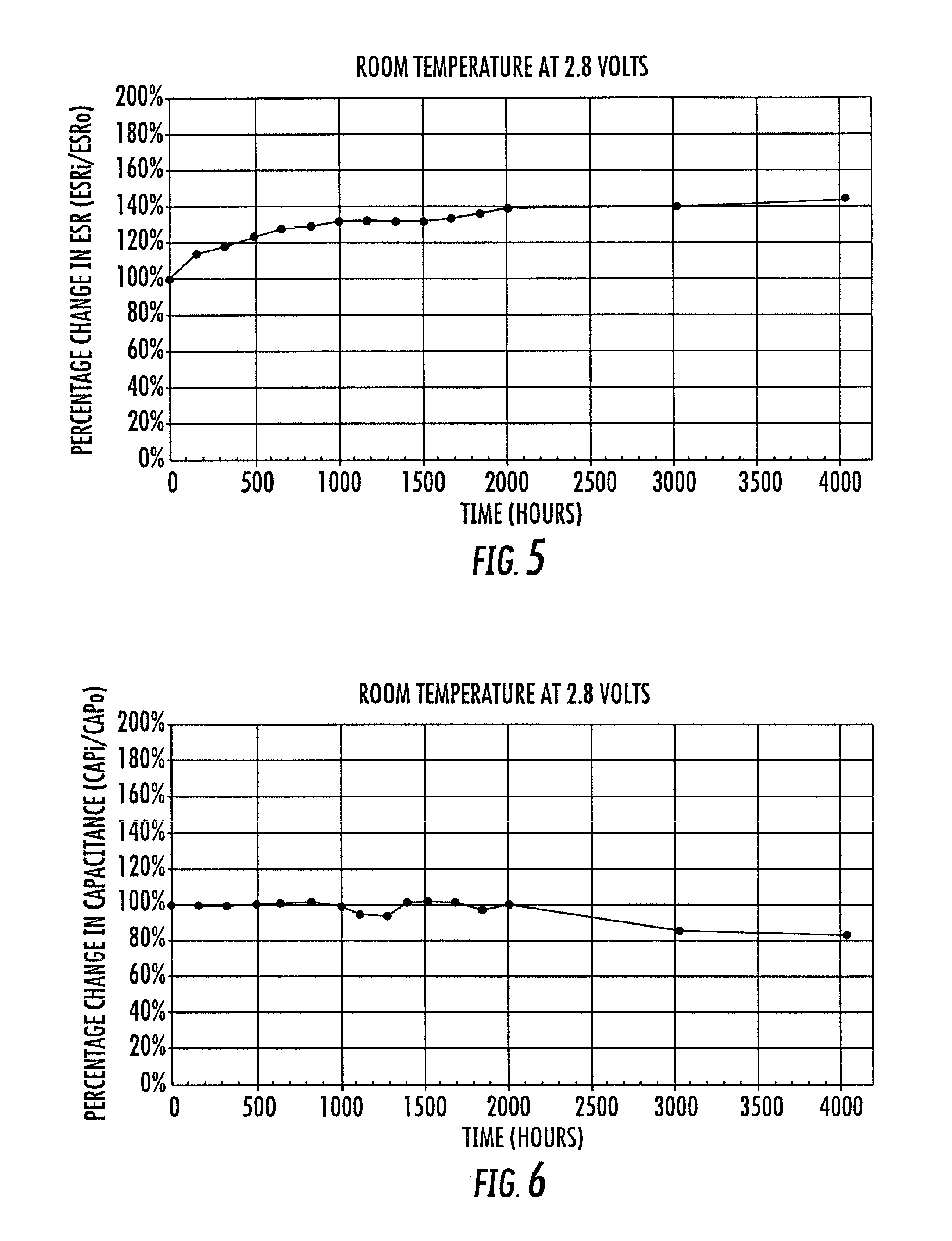
FIG. 5 is a graph of exemplary room temperature load-life (at 2.8 V load) versus percentage change of Equivalent Series Resistance (ESR) for an exemplary embodiment in accordance with the presently disclosed subject matter;
FIG. 6 is a graph of exemplary room temperature load-life (at 2.8 V load) versus percentage change of Capacitance for an exemplary embodiment in accordance with the presently disclosed subject matter;
FIG. 7 is a graph of exemplary room temperature load-life (at 2.8 V load) versus percentage change of Leakage Current for an exemplary embodiment in accordance with the presently disclosed subject matter;
FIG. 8 is a graph of exemplary shelf-life at temperatures of 75.degree. C., 85.degree. C., and 105.degree. C., respectively, versus percentage change in ESR for an exemplary embodiment in accordance with the presently disclosed subject matter;
FIG. 9 is a graph of exemplary shelf-life at temperatures of 75.degree. C., 85.degree. C., and 105.degree. C., respectively, versus percentage change in Capacitance for an exemplary embodiment in accordance with the presently disclosed subject matter;
FIG. 10 is a graph of exemplary load-life (at a temperature of 70.degree. C. and 2.2V load) versus percentage change in Leakage Current for an exemplary embodiment in accordance with the presently disclosed subject matter;
FIG. 11 is a graph of exemplary load-life (at a temperature of 50.degree. C. and 2.5V load) versus percentage change in Capacitance for an exemplary embodiment in accordance with the presently disclosed subject matter;
FIG. 12 is a graph of exemplary load-life (at a temperature of 50.degree. C. and 2.5V load) versus percentage change in Leakage Current for an exemplary embodiment in accordance with the presently disclosed subject matter;
FIG. 13 is a graph of exemplary ESR versus temperature for an exemplary embodiment in accordance with the presently disclosed subject matter;
FIG. 14 is a graph of exemplary Capacitance versus temperature for an exemplary embodiment in accordance with the presently disclosed subject matter;
FIG. 15 is a graph of exemplary Leakage Current versus temperature for an exemplary embodiment in accordance with the presently disclosed subject matter;
FIG. 16 is a graph of an exemplary GSM Waveform, showing both Voltage and Current versus time, which may be used in a voltage cycling test conducted with an exemplary embodiment in accordance with the presently disclosed subject matter;
FIG. 17 is a graph of exemplary percentage change in ESR versus number of cycles in GSM Waveform voltage cycling with an exemplary embodiment in accordance with the presently disclosed subject matter;
FIG. 18 is a graph of an exemplary Triangle Waveform, showing Voltage versus time, which may be used in a voltage cycling test conducted with an exemplary embodiment in accordance with the presently disclosed subject matter; and
FIG. 19 is a graph of exemplary percentage change in ESR versus number of cycles in Triangle Waveform voltage cycling with an exemplary embodiment in accordance with the presently disclosed subject matter.
Repeat use of references and descriptions throughout the present specification and appended drawings is intended to represent same or analogous features, elements, or steps of the presently disclosed subject matter.
DETAILED DESCRIPTION THE PREFERRED EMBODIMENTS
As discussed in the Summary of the Subject Matter section, the presently disclosed subject matter is generally concerned with certain organic electrolyte capacitor devices and related technology and manufacturing and/or mounting methodology. More particularly, the presently disclosed subject matter is concerned with improved designs for certain ultra-thin and ultra-low ESR supercapacitor components and energy storage component assemblies and related methodologies.
Selected combinations of aspects of the disclosed technology correspond to a plurality of different embodiments of the presently disclosed subject matter. It should be noted that each of the exemplary embodiments presented and discussed herein should not insinuate limitations of the presently disclosed subject matter. Features or steps illustrated or described as part of one embodiment may be used in combination with aspects of another embodiment to yield yet further embodiments. In additional, certain features may be interchanged with similar devices or features not expressly mentioned which perform the same or similar function.
Reference will now be made in detail to exemplary presently preferred embodiments, and for which FIG. 2 illustrates a schematic view of an exemplary electrochemical double layer capacitor (ECDL) device constructed in accordance with the presently disclosed technology. To better understand the presently disclosed subject matter, some additional background is provided for ECDL devices, as follows. FIG. 1 illustrates an exploded isometric view of layers comprising an exemplary prior art electrochemical energy storage device. See, for example, also FIG. 4 of commonly owned U.S. Pat. No. 6,576,365 (to Meitav, et al.), relating to electrochemical energy storage devices, and the complete disclosure of which is fully incorporated herein for all purposes. Generally speaking, such double layer capacitors have certain benefits compared with electronic technologies.
Considering how an electrochemical (ECDL) capacitor works, its most significant difference from an electronic capacitor is that the charge transfer is carried out by electrons in the electronic capacitor and by electrons and ions in the ECDL device. The anions and cations involved in double layer supercapacitors are contained in the electrolyte which may be liquid (sometimes an aqueous or organic solution) or solid. The solid electrolyte is frequently a conductive polymer.
Electrons are relatively fast moving and therefore transfer charge "instantly". However, ions have to move relatively slowly from anode to cathode. Thus, a finite amount of time is needed to establish the full nominal capacitance of the device. Such nominal capacitance is normally measured at 1 second. Various differences between EDLC (Electrochemical Double Layer Capacitors) and electronic capacitors may be summarized, as follows: A capacitor basically consists of two conductive plates (electrodes), separated by a layer of dielectric material, which may be such as ceramic, plastic film, paper, aluminum oxide, or similar. EDLCs do not use a discrete dielectric interphase separating the electrodes. EDLCs utilize the charge separation, which is formed across the electrode-electrolyte interface. The EDLC constitutes of two types of charge carriers: IONIC species on the ELECTROLYTE side and ELECTRONIC species on the ELECTRODE side.
The exploded isometric view of present FIG. 1 illustrates layers comprising a representative prior art electrochemical energy storage device.
In this instance, a case or frame provides form for common internal cell structure, with the outer layers (top and bottom) of the structure comprised of cell case materials comprising anode elements. A pair of current collectors may be provided as illustrated in representative prior art FIG. 1. They may comprise, for example, a first layer of conductive polymer that is in contact with the cell electrode. A second conductive structure (layer) may be preferably a metal, metal alloy, metallic film or a combination or mixture thereof displaying high conductivity, low contact resistance, and good adhesive properties to the conductive polymer layer or polymer composite.
One current collector may be adhered to the lower cell case while the other current collector is adjacent an electrode comprising the cathode of the arrangement. Thus, a layer of insulation material is represented between such cathode electrode and the cell case anode. Each current collector as illustrated is otherwise adjacent a layer of carbon, each of which may be in turn be adjacent a separator layer.
FIG. 2 illustrates a schematic view of an exemplary electrochemical double layer capacitor (ECDL) device constructed in accordance with the presently disclosed technology, and therefore comprising a very low ESR ECDL device or pulse supercapacitor (suitable for providing a pulse-capable energy storage device). As shown, a separator layer is sandwiched between a pair of electrodes with electrolyte, which are in turn exteriorly sandwiched by a pair of current collectors. Such electrolyte preferably comprises an organic electrolyte. For a number of presently disclosed embodiments, propylene carbonate (PC) electrolytes are preferred.
With such an arrangement, it's been shown possible to provide a carbon carbon (CC) capacitor with collective electrical characteristics of Low ESR from 50 to 300 m.OMEGA. (that is, a resistivity of no more than about 1.5 .OMEGA.cm.sup.2 of electrode area, and in some instances 1.3 .OMEGA.cm.sup.2 or less of electrode area), Capacitance of 1 to 10 F (that is, capacitance density of at least about 10 Farads per cc of active electrode volume), Leakage Current <50 .mu.A, and Voltage ratings of 2.1 to 4.2 V.
For one example application, Constant Power of 1 W is provided with 4 second back up), as follows:
Assume total .DELTA.V=1 V
.DELTA.V (total)=.DELTA.V.sub.esr+.DELTA.V.sub.cap
.DELTA.V.sub.esr=0.25*0.1=0.025 V (small drop)
Operating at 4 V, using .DELTA.V.sub.cap.about.1 V
Estimated C.about.1 Farad from I=C*dV/dt
(Note that voltage drop due to ESR is small, so even if it doubles the impact is small.)
For another example application, key electrical parameters which may be achieved through the presently disclosed technology includes a Capacitance of 1 F, a Voltage Rating of 4.2 volts, a Temperature Operational Range Rating of -40.degree. to 70.degree. C., and an ESR of 100 m.OMEGA..
The presently disclosed subject matter helps to address a desire for increased power density by, in part, using an organic electrolyte in place of water-based electrolyte, and in part, by using a very thin design (with the ability to stack layers) down to such as 0.5 mm (or less) instead of prior art devices more on the order of about 2 to 3 mm. Such an ultra-thin construction, with the ability to be put into parallel with batteries, can increase battery life (usage life) by 35%.
Another advantage of the presently disclosed subject matter is relatively increased operating temperature range. Preferably, for example, an electrolyte is used having a boiling point over 200.degree. C., such as up to 240.degree. C. A preferred example includes at least some of propylene carbonate (PC). If one practicing the presently disclosed subject matter makes use of thermally stable materials for sealant, then the electrolytes and terminals aren't a limitation in high temperature operational ranges. For example, increased temperature range abilities, to 90.degree. C. at half-rated voltage are possible, and with storage capabilities at 105.degree. C. such that the device still holds shape.
In general, an aspect of the presently disclosed subject matter also contributing to its ability to retain shape while withstanding relatively higher temperatures relates to manufacturing process. Advantageously, water/moisture is kept out of the manufacturing environment to a very high degree. For example, it is known for lithium oxide battery production to try and keep moisture to 0.01 to 0.1%, which relates to 100 to 1000 ppm water. However, in this instance, beneficial shape-resistance to heat is achieved in combination with the other aspects herewith disclosed by limiting moisture environment to only 0.001%, which relates to 10 ppm. At that very low moisture environment level, any enlargement as a response to performance at the limits of intended heat ranges is negligible.
Carbon carbon capacitor (CC Cap) constructions are achieved in part through use of very thin separator layers between the respective layers. As will be understood by those of ordinary skill in the art from the complete disclosure herewith, further embodiments may be formed stacking the thin capacitors to selectively achieve increased capacitance and/or voltage. For example, two devices of 2.1 volts each, placed in series can act as a substitute for a 3.6 v lithium battery. The resulting ultra-thin presently disclosed subject matter provides embodiments so small that it achieves for example the possibility of positioning a battery in an added case for a cell phone, due to the greatly reduced dimensions. In general, the presently disclosed ECDL electrochemical double layer capacitors (ECDL) subject matter can serve as supercaps or ultracaps, to provide energy storage devices useful for a variety of other product arrangements. One further example is for use in or as an uninterrupted power supply (UPS). Of course, various arrangements may result from series and/or parallel connected embodiments, to increase capacitance and/or voltage, as will be understood by those of ordinary skill in the art.
In general, the presently disclosed subject matter relates to an ultra-thin version of an ultra-low ESR supercap, which achieves increased power density in a supercapacitor through use of an ultra-low profile design making use of organic electrolyte materials. The resulting subject matter provides very thin devices, down to less than 0.5 mm thick, compared to typical prior art standards of 2 to 3 mm thick. Also, the new design has greatly increased high temperature performance, along with an increase in battery usage life. The presently disclosed very thin design coupled with the high temperature tolerant materials and presently disclosed manufacturing methodology provides excellent results for very low ESR characteristics. Further, the use of an embodiment specifying a propylene carbonate (PC) electrolyte, and having case dimensions of 50 mm long.times.40 mm wide.times.0.5 mm thick can also provide very low ESR characteristics.
Regarding very low ESR characteristics, results on the order of less than 150 milli-ohms are contemplated, even in combination with operation at an elevated temperature, or storage temperature of up to 105.degree. C.
FIGS. 3A and 3B are top and side edge elevational views, respectively, of an exemplary embodiment of an organic electrolyte capacitor device in accordance with presently disclosed subject matter, such as shown in greater detail in present FIG. 2. As shown, the exemplary case dimensions of such single cell arrangement are 50 mm long.times.40 mm wide.times.0.5 mm thick, and there is a pair of terminals associated with such case. FIG. 3C illustrates a likeness of the exemplary embodiment in accordance with the presently disclosed subject matter of FIGS. 3A and 3B.
FIGS. 4A and 4B are top and side edge elevational views, respectively, of another exemplary embodiment of an organic electrolyte capacitor device in accordance with presently disclosed subject matter, and illustrating an arranged pair of cells of a construction as shown in greater detail in present FIG. 2. As shown, the exemplary case dimensions of such double (twin) cell arrangement are 50 mm long.times.80 mm wide.times.0.5 mm thick, and there are two pairs of terminals associated with such embodiment. FIG. 4C illustrates a likeness of the exemplary embodiment in accordance with the presently disclosed subject matter of FIGS. 4A and 4B.
FIGS. 5, 6, and 7 are graphs of exemplary room temperature load-life (at 2.8 V load) versus percentage change of Equivalent Series Resistance (ESR), Capacitance, and Leakage Current for an exemplary embodiment in accordance with the presently disclosed subject matter. As shown, the graphs cover time exposure upwards of 4000 hours, to demonstrate reliability test data. The reflected data show good commercial performance in all categories tested. An additional aspect of such reliability testing, as will be understood by those of ordinary skill in the art, is that the testing voltage (2.8 V.sub.T) is intentionally much higher than the rated voltage (2.1 V.sub.R). Such an approach to testing well demonstrates that the devices being tested are regarded as robust because it is understood by those of ordinary skill in the art that electrochemical devices are in practice typically used at rated voltage or at lower than rated voltage. Thus, testing voltages herein (such as 2.8 V.sub.T) are not intended as conveying a higher rated voltage (such as 2.1 V.sub.R).
FIG. 8 and graphical illustrate reliability test data (over a 4000 hours axis) for exemplary shelf-life at respective temperatures of 75.degree. C., 85.degree. C., and 105.degree. C., respectively, for an exemplary embodiment in accordance with the presently disclosed subject matter. FIG. 8 data addresses percentage change in ESR while FIG. 9 data addresses percentage change in Capacitance. As shown, the presently disclosed subject matter shows good performance even when operating in extended temperature ranges.
FIG. 10 is a graph of exemplary load-life versus percentage change in Leakage Current for an exemplary embodiment in accordance with the presently disclosed subject matter. Measurements again are from a reliability test data perspective, and address operation at a temperature of 70.degree. C. and 2.2V load. FIGS. 11 and 12 are similar graphs but encompass addressing operation at a temperature of 50.degree. C. and 2.5V load. Graphs of FIGS. 11 and 12 also specifically indicate percentage changes in Capacitance and Leakage Current, respectively.
FIGS. 13, 14, and 15 graphically illustrate various electrical properties versus temperature, for an exemplary embodiment in accordance with the presently disclosed subject matter. FIG. 13 represents graphed percentage changes in ESR, showing that from 0.degree. C. and above, ESR is maintained within about .+-.50% of the room temperature value, so that a very low ESR is achieved over a wide temperature range, FIG. 14 represents changes in Capacitance and shows only about a .+-.25% change over a range from -40.degree. C. to 70.degree. C. FIG. 15 also shows stable Leakage Current performance over the indicated temperature range.
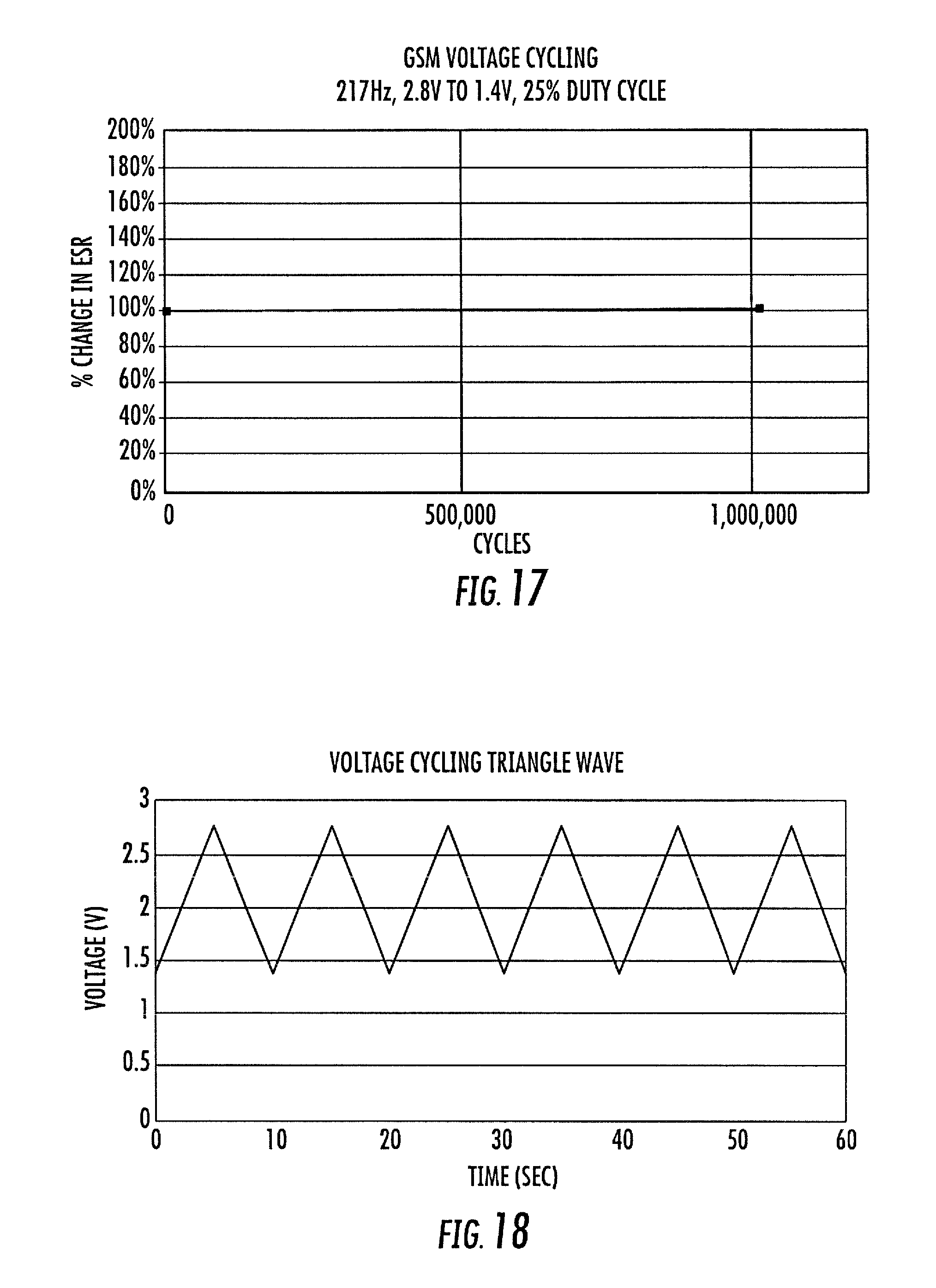
FIGS. 16 through 19 graphically illustrate pertinent data relative to voltage cycling testing of an exemplary embodiment in accordance with the presently disclosed subject matter, using a frequency generator and power amplifier testing arrangement. In particular, FIGS. 16 and 17 relate to test usage of an exemplary GSM Waveform, while FIGS. 18 and 19 relate to test usage of an exemplary Triangle Waveform. The indicated sample GSM waveform relates to a 217 Hz GSM Square Wave with a 25% duty cycle, shown over a 1.4V to 2.8V testing range. The indicated sample Triangle waveform reflects a 0.1 Hz Triangle Wave, also over a 1.4V to 2.8V testing range.
More particularly, FIG. 16 shows both Voltage and Current versus time for the exemplary GSM wave, which may be used in a voltage cycling test conducted with an exemplary embodiment in accordance with the presently disclosed subject matter, while FIG. 17 tracks endurance performance as an exemplary percentage change in ESR through one million cycles of such test waveform, FIG. 18 shows Voltage versus time for the exemplary Triangle wave, which may be used in a voltage cycling test conducted with an exemplary embodiment in accordance with the presently disclosed subject matter, while FIG. 19 tracks endurance performance as an exemplary percentage change in ESR through 150,000 cycles of such test waveform. Both FIGS. 17 and 19 reflect only generally negligible changes in ESR performance over such endurance cycle testing.
In sum, an exemplary embodiment of the presently disclosed subject matter may comprise exemplary case dimensions of 50 mm long.times.40 mm wide.times.0.5 mm thick, and with a pair of terminals associated with such case (see subject FIGS. 3A and 3B), and use preferably at least some of a propylene carbonate (PC) electrolyte. Such an exemplary embodiment may have a voltage rating (V.sub.r) of 2.1 Volts and a capacitance of 2.1 F/cc. It may provide good performance at 90.degree. C. and at 0.5 rated volts operation. At the same time, it can avoid bulging and maintain dimensional stability even at up to 105.degree. C. storage temperature, while also maintaining very low ESR of 150 milli-Ohms and normalized ESR/Cap of about 72 milli-Ohms/cc/F.
Overall, presently disclosed embodiments are capable of showing excellent high power pulse capabilities, together with low leakage currents over capacitance density greater than about 10 F/cc of active electrode volume. Testing data also shows enhanced temperature range performance, including no degradation of half-rated voltages at elevated temperatures and maintained shelf life and relatively higher temperatures (such as 105.degree. C.).
While the presently disclosed subject matter has been described in detail with respect to specific embodiments thereof, it will be appreciated that those skilled in the art, upon attaining an understanding of the foregoing may readily adapt the presently disclosed technology for alterations or additions to, variations of, and/or equivalents to such embodiments. Accordingly, the scope of the present disclosure is by way of example rather than by way of limitation, and the subject disclosure does not preclude inclusion of such modifications, variations, and/or additions to the presently disclosed subject matter as would be readily apparent to one of ordinary skill in the art.
* * * * *
D00000
D00001
D00002
D00003
D00004
D00005
D00006
D00007
D00008
D00009
D00010
D00011
D00012

D00013
D00014

XML
uspto.report is an independent third-party trademark research tool that is not affiliated, endorsed, or sponsored by the United States Patent and Trademark Office (USPTO) or any other governmental organization. The information provided by uspto.report is based on publicly available data at the time of writing and is intended for informational purposes only.
While we strive to provide accurate and up-to-date information, we do not guarantee the accuracy, completeness, reliability, or suitability of the information displayed on this site. The use of this site is at your own risk. Any reliance you place on such information is therefore strictly at your own risk.
All official trademark data, including owner information, should be verified by visiting the official USPTO website at www.uspto.gov. This site is not intended to replace professional legal advice and should not be used as a substitute for consulting with a legal professional who is knowledgeable about trademark law.