Particle sorting apparatus, particle sorting method, and program
Muraki , et al.
U.S. patent number 10,309,891 [Application Number 15/028,419] was granted by the patent office on 2019-06-04 for particle sorting apparatus, particle sorting method, and program. This patent grant is currently assigned to Sony Corporation. The grantee listed for this patent is Sony Corporation. Invention is credited to Yasunobu Kato, Yosuke Muraki, Fumitaka Otsuka.


| United States Patent | 10,309,891 |
| Muraki , et al. | June 4, 2019 |
Particle sorting apparatus, particle sorting method, and program
Abstract
[Object] To provide a particle sorting apparatus, a particle sorting method, and a program that are capable of efficiently sorting particles even when sizes of particles to be sorted are not uniform. [Solving Means] A particle sorting apparatus includes a charge section that imparts charges to at least a part of droplets discharged from an orifice from which a fluid stream is generated, and a charge control section that adjusts a charge amount to be imparted to the droplets by the charge section. Further, the charge control section is structured to adjust the charge amount according to sizes of particles included in the droplets.
| Inventors: | Muraki; Yosuke (Tokyo, JP), Otsuka; Fumitaka (Tokyo, JP), Kato; Yasunobu (Kanagawa, JP) | ||||||||||
|---|---|---|---|---|---|---|---|---|---|---|---|
| Applicant: |
|
||||||||||
| Assignee: | Sony Corporation (Tokyo,
JP) |
||||||||||
| Family ID: | 52827969 | ||||||||||
| Appl. No.: | 15/028,419 | ||||||||||
| Filed: | September 10, 2014 | ||||||||||
| PCT Filed: | September 10, 2014 | ||||||||||
| PCT No.: | PCT/JP2014/074610 | ||||||||||
| 371(c)(1),(2),(4) Date: | April 08, 2016 | ||||||||||
| PCT Pub. No.: | WO2015/056516 | ||||||||||
| PCT Pub. Date: | April 23, 2015 |
Prior Publication Data
| Document Identifier | Publication Date | |
|---|---|---|
| US 20160266027 A1 | Sep 15, 2016 | |
Foreign Application Priority Data
| Oct 16, 2013 [JP] | 2013-215736 | |||
| Current U.S. Class: | 1/1 |
| Current CPC Class: | B07C 5/342 (20130101); G01N 15/1436 (20130101); B01L 3/502776 (20130101); G01N 15/1404 (20130101); B01L 3/0268 (20130101); G01N 15/1425 (20130101); G01N 15/1459 (20130101); G01N 2015/149 (20130101); G01N 2015/1006 (20130101); B01L 2200/0652 (20130101); B03C 7/06 (20130101); G01N 15/1484 (20130101); G01N 2015/1081 (20130101); B01L 3/502723 (20130101); B01L 2400/0439 (20130101); G01N 2015/0065 (20130101); G01N 2015/142 (20130101) |
| Current International Class: | B03C 7/00 (20060101); G01N 15/14 (20060101); B07C 5/342 (20060101); B01L 3/02 (20060101); B01L 3/00 (20060101); B03C 7/06 (20060101); G01N 15/10 (20060101); G01N 15/00 (20060101) |
| Field of Search: | ;209/3,127.1,576,577 |
References Cited [Referenced By]
U.S. Patent Documents
| 3710933 | January 1973 | Fulwyler et al. |
| 3826364 | July 1974 | Bonner et al. |
| 3924947 | December 1975 | Hogg |
| 4009435 | February 1977 | Hogg |
| 4168460 | September 1979 | Menke |
| 4173415 | November 1979 | Wyatt |
| 4284496 | August 1981 | Newton |
| 4318480 | March 1982 | Lombardo et al. |
| 4318481 | March 1982 | Lombardo et al. |
| 4325483 | April 1982 | Lombardo et al. |
| 4538733 | September 1985 | Hoffman |
| 4616234 | October 1986 | Wint |
| 4987539 | January 1991 | Moore et al. |
| 5080770 | January 1992 | Culkin |
| 5180065 | January 1993 | Touge et al. |
| 5483469 | January 1996 | Van den Engh et al. |
| 5602039 | February 1997 | Van den Engh |
| 5700692 | December 1997 | Sweet |
| 5776781 | July 1998 | Vardanega et al. |
| 6079836 | June 2000 | Burr et al. |
| 6202734 | March 2001 | Sackinger et al. |
| 6248590 | June 2001 | Malachowski |
| 6372506 | April 2002 | Norton |
| 6410872 | June 2002 | Campbell et al. |
| 6589792 | July 2003 | Malachowski |
| 6861265 | March 2005 | den Engh |
| 6941005 | September 2005 | Lary et al. |
| 6949715 | September 2005 | Kelly |
| 7019293 | March 2006 | Hamada |
| 7024316 | April 2006 | Ellison et al. |
| 7159752 | January 2007 | Farnworth |
| 7417734 | August 2008 | Kanda |
| 7639358 | December 2009 | Kanda |
| 7691636 | April 2010 | Frazier et al. |
| 7723116 | May 2010 | Evans et al. |
| 7758811 | July 2010 | Durack et al. |
| 7880108 | February 2011 | Schembri et al. |
| 7901947 | March 2011 | Pollack et al. |
| 8246805 | August 2012 | Shinoda |
| 8570511 | October 2013 | Wang |
| 8681335 | March 2014 | Sharpe et al. |
| 8691584 | April 2014 | Durack et al. |
| 8748183 | June 2014 | Durack et al. |
| 8883513 | November 2014 | Pollack et al. |
| 8922636 | December 2014 | Belden et al. |
| 8922646 | December 2014 | Neckels et al. |
| 9029724 | May 2015 | Hashimoto et al. |
| 9087371 | July 2015 | Muraki |
| 9339823 | May 2016 | Muraki et al. |
| 9429276 | August 2016 | Katsumoto |
| 9588036 | March 2017 | Shinoda |
| 9784659 | October 2017 | Tanase et al. |
| 9784660 | October 2017 | Otsuka et al. |
| 9857286 | January 2018 | Muraki et al. |
| 9958375 | May 2018 | Muraki et al. |
| 10132735 | November 2018 | Muraki |
| 2002/0171827 | November 2002 | van den Engh |
| 2003/0222950 | December 2003 | Jeanmaire |
| 2004/0062685 | April 2004 | Norton et al. |
| 2004/0086159 | May 2004 | Lary et al. |
| 2006/0125856 | June 2006 | Kitami et al. |
| 2006/0177348 | August 2006 | Yasuda et al. |
| 2007/0102634 | May 2007 | Frey et al. |
| 2007/0195310 | August 2007 | Kanda |
| 2007/0257215 | November 2007 | Rich |
| 2008/0024619 | January 2008 | Ono |
| 2008/0050283 | February 2008 | Chou et al. |
| 2008/0053205 | March 2008 | Pollack et al. |
| 2008/0067068 | March 2008 | Li |
| 2008/0092655 | April 2008 | Takiguchi |
| 2008/0255705 | October 2008 | Degeal et al. |
| 2008/0284827 | November 2008 | Fagerquist et al. |
| 2008/0289966 | November 2008 | Voldman et al. |
| 2009/0125242 | May 2009 | Choi et al. |
| 2009/0170186 | July 2009 | Wu et al. |
| 2010/0009445 | January 2010 | Patra et al. |
| 2010/0118300 | May 2010 | Wang et al. |
| 2010/0315639 | December 2010 | Muraki |
| 2011/0005931 | January 2011 | Zhe et al. |
| 2011/0033339 | February 2011 | Muraki |
| 2011/0081684 | April 2011 | Gauer et al. |
| 2011/0221892 | September 2011 | Neckels et al. |
| 2011/0259749 | October 2011 | Kanda |
| 2011/0267457 | November 2011 | Weitz et al. |
| 2011/0275052 | November 2011 | Schenk et al. |
| 2011/0284378 | November 2011 | Shinoda |
| 2011/0287976 | November 2011 | Wang et al. |
| 2012/0076349 | March 2012 | Manri et al. |
| 2012/0084022 | April 2012 | Giovangrandi et al. |
| 2012/0135874 | May 2012 | Wang et al. |
| 2012/0200857 | August 2012 | Sharpe et al. |
| 2012/0202237 | August 2012 | Sedoglavich et al. |
| 2012/0247231 | October 2012 | Kery et al. |
| 2012/0301869 | November 2012 | Evans |
| 2012/0314096 | December 2012 | Kruglick |
| 2013/0188040 | July 2013 | Kamen et al. |
| 2013/0194589 | August 2013 | Suzuki |
| 2013/0256136 | October 2013 | Muraki |
| 2013/0256197 | October 2013 | Katsumoto |
| 2013/0258075 | October 2013 | Muraki et al. |
| 2013/0286038 | October 2013 | Kamath et al. |
| 2014/0021370 | January 2014 | Suzuki et al. |
| 2014/0043436 | February 2014 | Bell et al. |
| 2014/0087453 | March 2014 | Tahara |
| 2014/0097129 | April 2014 | Foster et al. |
| 2014/0144817 | May 2014 | Hashimoto et al. |
| 2014/0174206 | June 2014 | Akiyama et al. |
| 2014/0193059 | July 2014 | Muraki |
| 2014/0208875 | July 2014 | Muraki |
| 2014/0212917 | July 2014 | Durack et al. |
| 2014/0346047 | November 2014 | Shinoda |
| 2014/0354795 | December 2014 | Tracy et al. |
| 2015/0057787 | February 2015 | Muraki et al. |
| 2015/0068957 | March 2015 | Otsuka et al. |
| 2015/0204774 | July 2015 | Ito |
| 2015/0285726 | October 2015 | Tanase et al. |
| 2015/0285727 | October 2015 | Muraki |
| 2015/0377763 | December 2015 | Brun et al. |
| 2016/0148433 | May 2016 | Petrovskaya et al. |
| 2016/0223451 | August 2016 | Muraki et al. |
| 2016/0245736 | August 2016 | Muraki et al. |
| 2017/0191925 | July 2017 | Otsuka et al. |
| 2017/0241889 | August 2017 | Otsuka et al. |
| 2018/0058999 | March 2018 | Otsuka et al. |
| 2018/0188150 | July 2018 | Muraki et al. |
| 2018/0313740 | November 2018 | Otsuka |
| 1950690 | Apr 2007 | CN | |||
| 1403633 | Mar 2004 | EP | |||
| 1 103 190 | Feb 1968 | GB | |||
| 53-013263 | Feb 1978 | JP | |||
| 56-030870 | Mar 1981 | JP | |||
| 58-187441 | Dec 1983 | JP | |||
| 62-036542 | Feb 1987 | JP | |||
| 62-167478 | Jul 1987 | JP | |||
| 64-012245 | Jan 1989 | JP | |||
| 09-189653 | Jul 1997 | JP | |||
| H09-196855 | Jul 1997 | JP | |||
| 10-507525 | Jul 1998 | JP | |||
| 11-501258 | Feb 1999 | JP | |||
| 2002-505423 | Feb 2002 | JP | |||
| 2002-521658 | Jul 2002 | JP | |||
| 2004-257756 | Sep 2004 | JP | |||
| 2005-315799 | Nov 2005 | JP | |||
| 2006-504970 | Feb 2006 | JP | |||
| 2006-242849 | Sep 2006 | JP | |||
| 2006-292769 | Oct 2006 | JP | |||
| 2007-532874 | Nov 2007 | JP | |||
| 2008-107110 | May 2008 | JP | |||
| 2009-145213 | Jul 2009 | JP | |||
| 2009-198511 | Sep 2009 | JP | |||
| 2009-541093 | Nov 2009 | JP | |||
| 2009-298012 | Dec 2009 | JP | |||
| 2010-510782 | Apr 2010 | JP | |||
| 2010-190680 | Sep 2010 | JP | |||
| 2010-216992 | Sep 2010 | JP | |||
| 2010-286292 | Dec 2010 | JP | |||
| 2010-286341 | Dec 2010 | JP | |||
| 2011-033598 | Feb 2011 | JP | |||
| 2011-509075 | Mar 2011 | JP | |||
| 2011-232033 | Nov 2011 | JP | |||
| 2011-237201 | Nov 2011 | JP | |||
| 4805417 | Nov 2011 | JP | |||
| 2012-047464 | Mar 2012 | JP | |||
| 2013-210264 | Oct 2013 | JP | |||
| 2013-210270 | Oct 2013 | JP | |||
| 2015-152439 | Aug 2015 | JP | |||
| WO 2001/002836 | Jan 2001 | WO | |||
| WO 2010/095391 | Aug 2010 | WO | |||
| WO 2010/129787 | Nov 2010 | WO | |||
| WO 2010/140460 | Dec 2010 | WO | |||
| WO 2013/145905 | Oct 2013 | WO | |||
| WO 2014/115409 | Jul 2014 | WO | |||
Other References
|
Yoshimura et al., The Latest Technology [Modern Technology] of a Cell Sorter, Applied Research Report, Jasco Report. 1990;31(1):1-20. cited by applicant . Bonner et al., Flourescence Activated Cell Sorting. Review of Scientific Instruments. Mar. 1972; 43(3):404-9. cited by applicant . International Search Report and English translation thereof dated Sep. 27, 2016 in connection with International Application No. PCT/JP2016/070938. cited by applicant . International Search Report and Written Opinion dated Nov. 6, 2015 in connection with International Application No. PCT/JP2015/004282. cited by applicant . International Preliminary Report on Patentability dated Mar. 16, 2017 in connection with International Application No. PCT/JP2015/004282. cited by applicant . International Search Report and Written Opinion and English translation thereof dated Feb. 24, 2015 in connection with International Application No. PCT/JP2014/080588. cited by applicant . Japanese Office Action and English translation thereof dated Dec. 15, 2015 in connection with Japanese Application No. 2012-080366. cited by applicant . Chinese Office Action and English translation thereof dated Mar. 3, 2016 in connection with Chinese Application No. 2013100954250. cited by applicant . International Search Report and Written Opinion dated Mar. 11, 2014 in connection with International Application No. PCT/JP2013/005910. cited by applicant . International Preliminary Report on Patentability dated May 21, 2015 in connection with International Application No. PCT/JP2013/005910. cited by applicant . Japanese Office Action dated Feb. 23, 2016 in connection with Japanese Application No. 2012-246432 and English translation thereof. cited by applicant . International Search Report and English translation thereof dated Mar. 12, 2013 in connection with Application No. PCT/JP2013/053324. cited by applicant . International Preliminary Report on Patentability and English translation thereof dated Oct. 9, 2014 in connection with Application No. PCT/JP2013/053324. cited by applicant . Extended European Search Report dated Aug. 26, 2014 in connection with Application No. 13768656.4. cited by applicant . International Search Report and Written Opinion and English translation thereof dated Mar. 5, 2013 in connection with Application No. PCT/JP2013/052467. cited by applicant . Japanese Office Action dated Jul. 15, 2014 and English translation thereof in connection with Application No. 2013-547043. cited by applicant . International Search Report and Written Opinion and English translation thereof dated Mar. 5, 2013 in connection with Application No. PCT/JP2013/051800. cited by applicant . International Search Report and Written Opinion and English translation thereof dated Jan. 21, 2014 in connection with Application No. PCT/JP2013/081152. cited by applicant . International Preliminary Report on Patentability and English translation thereof dated Oct. 9, 2014 in connection with Application No. PCT/JP2013/051800. cited by applicant . Chinese Office Action dated Aug. 25, 2015 in connection with Chinese Application No. 2013800154978 and English translation thereof. cited by applicant . Extended European Search Report dated Sep. 23, 2016 in connection with European Application No. 13872550.2. cited by applicant . International Preliminary Report on Patentability and English translation thereof dated Aug. 6, 2015 in connection with Application No. PCT/JP2013/081152. cited by applicant . McIntyre et all., Quantitative SLM-based differential interference contrast imaging. Optics Express. Jun. 2010; 18(13):14063-78. cited by applicant . No Author Listed, Differential Interference Contrast, Olympus Microscopy Resource Center, https://web.archive.org/web/20160510073659/http://www.olympusmicro.com:80- /primer/techniques/dic/dichome.html, retrieved from the WayBack Machine on Mar. 22, 2018, noting date of May 10, 2016, 2 pages. cited by applicant . No Author Listed, The EPICS.RTM. ALTRA.TM. Flow Cytometer, Sorting Tutorial, Jul. 1, 2000, Coulter International Corporation, 47 pages. cited by applicant . Shapiro, HM, Chapter 6: Flow Sorting, Practical Flow Cytometry, 4th Edition, Dec. 31, 2003, pp. 257-271. cited by applicant . Murphy et al., Differential Interference Contrast, Olympus Microscopy Resource Center, https://web.archive.org/web/20030312041453/http://www.olympusmicro.com:80- /primer/techniques/dic/dichome.html, retrieved from the WayBack Machine on Mar. 30, 2018, noting date of Mar. 12, 2003, 3 pages. cited by applicant . U.S. Appl. No. 15/907,805, filed Feb. 28, 2018, Muraki et al. cited by applicant . U.S. Appl. No. 15/506,497, filed Feb. 24, 2017, Otsuka et al. cited by applicant . U.S. Appl. No. 15/116,830, filed Aug. 5, 2016, Otsuka et al. cited by applicant . U.S. Appl. No. 13/788,075, filed Mar. 7, 2013, Muraki et al. cited by applicant . U.S. Appl. No. 13/788,165, filed Mar. 7, 2013, Muraki et al. cited by applicant . U.S. Appl. No. 14/026,023, filed Sep. 13, 2013, Tahara. cited by applicant . U.S. Appl. No. 14/118,788, filed Nov. 19, 2013, Muraki. cited by applicant . U.S. Appl. No. 14/188,994, filed Nov. 20, 2013, Hashimoto et al. cited by applicant . U.S. Appl. No. 14/239,794, filed Feb. 20, 2014, Muraki. cited by applicant . U.S. Appl. No. 14/386,368, filed Sep. 19, 2014, Otsuka et al. cited by applicant . U.S. Appl. No. 14/386,499, filed Sep. 19, 2014, Muraki et al. cited by applicant . U.S. Appl. No. 14/413,543, filed Jan. 8, 2015, Ito. cited by applicant . U.S. Appl. No. 14/440,765, filed May 5, 2015, Tanase et al. cited by applicant . U.S. Appl. No. 14/737,370, filed Jun. 11, 2015, Muraki. cited by applicant . U.S. Appl. No. 14/763,980, filed Jul. 28, 2015, Brun et al. cited by applicant . U.S. Appl. No. 15/028,411, filed Apr. 8, 2016, Muraki et al. cited by applicant . U.S. Appl. No. 15/093,879, filed Apr. 8, 2016, Muraki et al. cited by applicant . Written Opinion and English translation thereof dated Sep. 27, 2016 in connection with International Application No. PCT/JP2016/070938. cited by applicant . International Preliminary Report on Patentability and English translation thereof dated May 3, 2018 in connection with International Application No. PCT/JP2016/070938. cited by applicant . International Search Report and Written Opinion dated Jan. 8, 2015 in connection with International Application No. PCT/JP2014/005167. cited by applicant . International Preliminary Report on Patentability dated Apr. 28, 2016 in connection with International Application No. PCT/JP2014/005167. cited by applicant . International Search Report and Written Opinion and English translation thereof dated Nov. 18, 2014 in connection with International Application No. PCT/JP2014/074610. cited by applicant . International Preliminary Report on Patentability and English translation thereof dated Apr. 28, 2016 in connection with International Application No. PCT/JP2014/074610. cited by applicant . International Preliminary Report on Patentability and English translation thereof dated Aug. 25, 2016 in connection with International Application No. PCT/JP2014/080588. cited by applicant . Hartman et al., Jet break-up in electrohydrodynamic atomization in the cone-jet mode. J. Aerosol Sci. vol. 31(1), pp. 65-95; Mar. 1999. cited by applicant . Orme et al., Electrostatic charging and deflection of nonconventional droplet streams formed from capillary stream breakup. Phys. Fluids. vol. 12(9); Sep. 2000; pp. 2224-2235. cited by applicant . Yoon et al., 3D particle position and 3D velocity field measurement in microvolume via the defocusing concept. Meas. Sci. Technol. 17 (2006) 2897-2905. cited by applicant . Morton et al., Hydrodynamic metamaterials: Microfabricated arrays to steer, refract, and focus streams of biomaterials. PNAS May 27, 2008. vol. 105(21); 7434-7438. cited by applicant . Luo et al., Three-dimensional tracking of fluorescent particles applied to micro-fluidic measurements. 2006. J. Micromech. Microeng. vol. 16; 1689-1699. cited by applicant . Japanese Office Action dated Feb. 26, 2019 in connection with Japanese Application No. 2015-137487, and English translation thereof. cited by applicant . Pereira et al., Defocusing digital particle image velocimetry and the three-dimensional characterization of two-phase flows. 2002. Meas. Sci. Technol. vol. 13; pp. 683-694. cited by applicant. |
Primary Examiner: Rodriguez; Joseph C
Assistant Examiner: Kumar; Kalyanavenkateshware
Attorney, Agent or Firm: Wolf, Greenfield & Sacks, P.C.
Claims
The invention claimed is:
1. A particle sorting apparatus, comprising: a charge section that imparts charges to at least a part of droplets discharged from an orifice from which a fluid stream is generated; and a charge control section that adjusts a charge amount to be imparted by the charge section according to sizes of particles included in the droplets based on a result of scattered light emitted from the particles by irradiating light onto particles; an image pickup device that picks up an image of a state of the droplets; and a droplet judgment section that judges the state of the droplets from the image picked up by the image pickup device, wherein the charge control section adjusts the charge amount when the droplet judgment section judges that an adjustment is necessary; wherein the droplet judgment section judges that the adjustment is necessary when a small droplet not including the particles exists around the droplets including the particles; wherein the sizes of the particles in the droplets are not uniform.
2. The particle sorting apparatus according to claim 1, further comprising a forward-scattered light detection section that irradiates light onto particles flowing through a flow channel and detects forward-scattered light emitted from the particles by the light irradiation, wherein the charge control section determines, based on a result of the detection by the forward-scattered light detection section, the charge amount to be imparted to the droplets including the particles.
3. The particle sorting apparatus according to claim 2, wherein the charge control section controls the charge section to: impart a first charge amount to the droplets including the particles when an intensity of forward-scattered light detected by the forward-scattered light detection section is smaller than a preset threshold value; and impart a second charge amount different from the first charge amount to the droplets including the particles when the intensity of forward-scattered light detected by the forward-scattered light detection section is equal to or larger than the preset threshold value.
4. The particle sorting apparatus according to claim 3, wherein the second charge amount is larger than the first charge amount.
5. The particle sorting apparatus according to claim 2, wherein the charge control section changes the charge amount to be imparted to the droplets including the particles in proportion to an intensity of forward-scattered light detected by the forward-scattered light detection section.
6. The particle sorting apparatus according to claim 1, wherein: the charge section includes a charge electrode that is provided while being in contact with a sheath fluid and/or a sample fluid flowing through a flow channel; and the charge control section changes a voltage to be applied to the charge electrode to adjust the charge amount to be imparted to the droplets.
7. The particle sorting apparatus according to claim 6, wherein the orifice is formed in a replaceable microchip, and the charge electrode is provided in a sheath fluid flow channel provided in the microchip.
8. A particle sorting method, comprising the steps of: imparting charges to at least a part of droplets discharged from an orifice from which a fluid stream is generated; and adjusting a charge amount to be imparted to the droplets according to sizes of particles included in the droplets based on a result of scattered light emitted from the particles by irradiating light onto particles; an image pickup device that picks up an image of a state of the droplets; and a droplet judgment section that judges the state of the droplets from the image picked up by the image pickup device, wherein the charge control section adjusts the charge amount when the droplet judgment section judges that an adjustment is necessary; wherein the droplet judgment section judges that the adjustment is necessary when a small droplet not including the particles exists around the droplets including the particles; wherein the sizes of the particles in the droplets are not uniform.
9. A non-transitory computer readable storage medium having computer readable instructions stored thereon that, when executed, cause a charge control section of a particle sorting apparatus to execute a function of adjusting, according to sizes of particles included in droplets discharged from an orifice from which a fluid stream is generated, a charge amount to be imparted to the droplets based on a result of scattered light emitted from the particles by irradiating light onto particles; an image pickup device that picks up an image of a state of the droplets; and a droplet judgment section that judges the state of the droplets from the image picked up by the image pickup device, wherein the charge control section adjusts the charge amount when the droplet judgment section judges that an adjustment is necessary; wherein the droplet judgment section judges that the adjustment is necessary when a small droplet not including the particles exists around the droplets including the particles; wherein the sizes of the particles in the droplets are not uniform.
Description
CROSS REFERENCE TO RELATED APPLICATIONS
The present application is a U.S. National Stage Application under 35 U.S.C. .sctn. 371, based on International Application No. PCT/JP2014/074610, filed Sep. 10, 2014, which claims priority to Japanese Patent Application JP 2013-215736, filed Oct. 16, 2013, the entire contents of each of which is incorporated herein by reference.
TECHNICAL FIELD
The present technique relates to a particle sorting apparatus, a particle sorting method, and a program, more specifically, to a technique of sorting particles based on an analysis result using an optical method or the like.
BACKGROUND ART
From the past, an optical measurement method that uses flow cytometry (flow cytometer) has been used for analyzing biologically-relevant micro-particles such as cells, microorganisms, and liposomes. A flow cytometer is an apparatus that irradiates light onto micro-particles flowing through a flow channel formed in a flow cell, a microchip, and the like and detects and analyzes fluorescence and scattered light emitted from the individual micro-particles.
Some flow cytometers include a function of sorting and recovering only micro-particles having a specific property based on an analysis result, and a micro-particle apparatus that sorts cells in particular is called "cell sorter". In such a cell sorter, in general, a flow cell or a microchip is vibrated by a vibration device or the like to form droplets of a fluid discharged from the flow channel (see Patent Documents 1 and 2).
After the droplets separated from the fluid is imparted with charges of plus (+) and minus (-), a traveling direction thereof is changed by a deflection plate or the like so that the droplets are recovered in a predetermined vessel or the like. Further, from the past, there has also been proposed a technique of distributing particular cells one by one to each reaction site of a base material used in a PCR (Polymerase Chain Reaction) method or the like using a sorting function of a cell sorter (see Patent Document 3).
Patent Document 1: Japanese Patent Translation Publication No. 2007-532874
Patent Document 2: Japanese Patent Application Laid-open No. 2010-190680
Patent Document 3: Japanese Patent Translation Publication No. 2010-510782
SUMMARY OF INVENTION
Problem to be Solved by the Invention
However, the particle sorting apparatus of the related art described above has a problem that when particles of different sizes coexist in a sample fluid, the traveling direction of droplets becomes unstable so as not to be distributed to a predetermined vessel or reaction site, thus resulting in lowering of sorting accuracy and sorting efficiency.
In this regard, the present disclosure aims at providing a particle sorting apparatus, a particle sorting method, and a program that are capable of efficiently sorting particles even when sizes of particles to be sorted are not uniform.
Means for Solving the Problem
According to the present disclosure, there is provided a particle sorting apparatus including: a charge section that imparts charges to at least a part of droplets discharged from an orifice from which a fluid stream is generated; and a charge control section that adjusts a charge amount to be imparted by the charge section according to sizes of particles included in the droplets.
When the particle sorting apparatus further includes a forward-scattered light detection section that irradiates light onto particles flowing through a flow channel and detects forward-scattered light emitted from the particles by the light irradiation, the charge control section may determine, based on a result of the detection by the forward-scattered light detection section, the charge amount to be imparted to the droplets including the particles.
The charge control section may control the charge section to: impart a first charge amount to the droplets including the particles when an intensity of forward-scattered light detected by the forward-scattered light detection section is smaller than a preset threshold value; and impart a second charge amount different from the first charge amount to the droplets including the particles when the intensity of forward-scattered light detected by the forward-scattered light detection section is equal to or larger than the preset threshold value.
In this case, the second charge amount may be set to be larger than the first charge amount.
The charge control section may change the charge amount to be imparted to the droplets including the particles in proportion to an intensity of forward-scattered light detected by the forward-scattered light detection section.
The charge section may include a charge electrode that is provided while being in contact with a sheath fluid and/or a sample fluid flowing through a flow channel, and the charge control section may change a voltage to be applied to the charge electrode to adjust the charge amount to be imparted to the droplets.
The orifice may be formed in a replaceable microchip. In this case, the charge electrode may be provided in a sheath fluid flow channel provided in the microchip.
The particle sorting apparatus according to the present disclosure may further include: an image pickup device that picks up an image of a state of the droplets; and a droplet judgment section that judges the state of the droplets from the image picked up by the image pickup device, and the charge control section may adjust the charge amount when the droplet judgment section judges that an adjustment is necessary.
The droplet judgment section may judge that the adjustment is necessary when a small droplet not including the particles exists around the droplets including the particles.
According to the present disclosure, there is provided a particle sorting method including the steps of: imparting charges to at least a part of droplets discharged from an orifice from which a fluid stream is generated; and adjusting a charge amount to be imparted to the droplets according to sizes of particles included in the droplets.
According to the present disclosure, there is provided a program that causes a charge control section of a particle sorting apparatus to execute a function of adjusting, according to sizes of particles included in droplets discharged from an orifice from which a fluid stream is generated, a charge amount to be imparted to the droplets.
Effects of the Invention
According to the present disclosure, target particles can be efficiently sorted irrespective of the particle sizes. It should be noted that the effects described herein are not necessarily limited, and any effect described in the present disclosure may be obtained.
BRIEF DESCRIPTION OF DRAWINGS
FIG. 1 A diagram schematically showing a structural example of a particle sorting apparatus according to a first embodiment of the present disclosure.
FIG. 2 A figure substitution graph showing a detection result of particles in a photodetector, the abscissa axis representing an intensity of forward-scattered light and the ordinate axis representing an intensity of backscattered light.
FIG. 3 A figure substitution graph showing an example of a charge amount adjustment method by a charge control section 7.
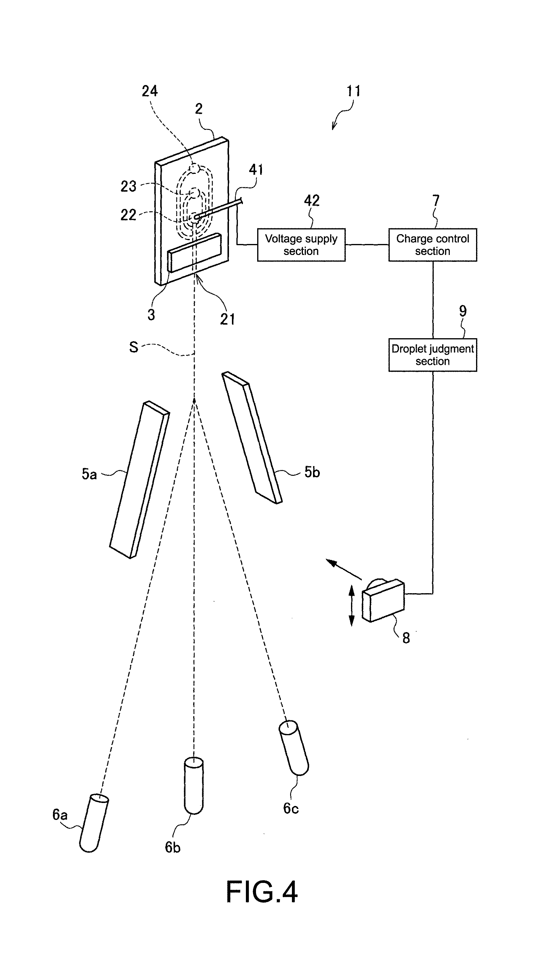
FIG. 4 A diagram schematically showing a structural example of a particle sorting apparatus according to a second embodiment of the present disclosure.
FIGS. 5A and 5B are diagrams each showing an image taken by a camera 8.
MODES FOR CARRYING OUT THE INVENTION
Hereinafter, embodiments of the present disclosure will be described in detail with reference to the attached drawings. It should be noted that the present disclosure is not limited to the following embodiments. Moreover, the descriptions will be given in the following order.
1. First Embodiment
(Example of Sorting Apparatus that Adjusts Charge Amount Based on Particle Size)
2. Second Embodiment
(Example of Sorting Apparatus that Judges Whether to Perform Adjustment Based on Picked-Up Droplet Image)
1. First Embodiment
First, a particle sorting apparatus according to a first embodiment of the present disclosure will be described. FIG. 1 is a diagram showing a schematic structure of the particle sorting apparatus according to the first embodiment of the present disclosure.
(Entire Structure of Apparatus)
The particle sorting apparatus 1 of this embodiment sorts and recovers particles based on a result of an analysis using an optical method or the like. As shown in FIG. 1, the particle sorting apparatus 1 includes a microchip 2, a vibration device 3, a charge section 4, a charge control section 7, and deflection plates 5a and 5b.
(Particles)
Particles analyzed and sorted by the particle sorting apparatus 1 of this embodiment widely include biologically-relevant micro-particles such as cells, microorganisms, and liposomes and synthetic particles such as latex particles, gel particles, and industrial particles.
Biologically-relevant micro-particles include chromosomes, liposomes, mitochondria, and organelle (cell organelle) constituting various cells. In addition, cells include plant cells, animal cells, and hemocyte cells. Further, microorganisms include bacteria such as coliform bacillus, viruses such as tobacco mosaic virus, and fungi such as yeast. The biologically-relevant micro-particles may also include biologically-relevant polymer molecules such as nucleic acid, protein, and a complex of those.
On the other hand, industrial particles include particles formed of, for example, an organic polymer material, an inorganic material, and a metal material. As the organic polymer material, polystyrene, styrene divinylbenzene, polymethyl methacrylate, or the like can be used. Moreover, as the inorganic material, glass, silica, a magnetic material, or the like can be used. As the metal material, for example, gold colloid or aluminum can be used. It should be noted that the shape of the particles is generally a sphere, but the shape may be an aspherical shape, and the size, mass, and the like are also not limited in particular.
(Microchip 2)
Formed in the microchip 2 are a sample inlet 22 into which a fluid including particles to be sorted (sample fluid) is introduced, a sheath inlet 23 into which a sheath fluid is introduced, a suction outlet 24 for eliminating clogging and air bubbles, and the like. In the microchip 2, a sample fluid is introduced into the sample inlet 22 to join a sheath fluid introduced into the sheath inlet 23 and is thereafter sent into a sample flow channel to be discharged from an orifice 21 provided at a terminal of the sample flow channel.
Further, a suction flow channel that is in communication with the suction outlet 24 is connected to the sample flow channel. The suction flow channel is used for eliminating, when clogging or air bubble is caused in the sample flow channel, the clogging or air bubble by setting the inside of the sample flow channel to a negative pressure to temporarily cause back-flow. A negative pressure source such as a vacuum pump is connected to the suction outlet 24.
The microchip 2 can be formed of glass and various plastics (PP, PC, COP, PDMS, etc.). The material of the microchip 2 is desirably a material that has permeability with respect to measurement light irradiated from a photodetector to be described later, less auto-fluorescence, and less optical errors due to a small wavelength dispersion.
The microchip 2 can be formed by wet etching or dry etching on a glass substrate or nanoimprint, injection molding, and mechanical processing on a plastic substrate. The microchip 2 can be formed by, for example, sealing a substrate on which a sample flow channel or the like is formed by a substrate formed of the same material or a different material.
(Vibration Device 3)
The vibration device 3 is provided while being in contact with a part of the microchip 2 or as an internal structure of the microchip 2. The vibration device 3 causes the microchip 2 to vibrate at a predetermined frequency and causes minute vibrations with respect to the sheath fluid to form droplets of the fluids (sample fluid and sheath fluid) discharged from the orifice 21, with the result that a fluid stream (flow of droplets) S is generated. As the vibration device 3, a piezo device or the like can be used.
(Charge Section 4)
The charge section 4 imparts positive or negative charges to the droplets discharged from the orifice 21 and is constituted of a charge electrode 41, a voltage source (voltage supply section 42) that applies a predetermined voltage to the charge electrode 41, and the like. The charge electrode 41 is provided while being in contact with the sheath fluid and/or sample fluid flowing through the flow channel and imparts charges to the sheath fluid and/or sample fluid. The charge electrode 41 is inserted into, for example, a charge electrode inlet of the microchip 2.
It should be noted that although the charge electrode 41 is in contact with the sample fluid in FIG. 1, the present disclosure is not limited thereto, and the charge electrode 41 may be provided in contact with the sheath fluid or both the sample fluid and the sheath fluid. It should be noted that considering influences on cells to be sorted, it is desirable to set the charge electrode 41 so that it comes into contact with the sheath fluid.
As described above, by imparting positive or negative charges to desired droplets to charge them, the droplets including arbitrary particles can be separated by an electrical force. Moreover, by synchronizing the charge timing of the charge section 4 and the supply voltage with respect to the vibration device 3, it becomes possible to charge only the arbitrary droplets.
(Deflection Plates 5a and 5b)
The deflection plates 5a and 5b change the traveling direction of the droplets in the fluid stream S by an electrical force that operates among charges imparted to the droplets and induce them to predetermined recovery vessels 6a to 6c, and are provided opposed to each other while sandwiching the fluid stream S. Normally-used electrodes can be used as the deflection plates 5a and 5b, for example.
Different positive or negative voltages are applied to the deflection plates 5a and 5b. As a result, as the charged droplets pass the formed electrical field, an electrical force (coulomb force) is generated, and the droplets are drawn to a direction of either one of the deflection plates 5a and 5b. In the particle sorting apparatus 1, it is possible to control the flow of droplets (side stream) drawn by an electrical field by varying the positive/negative or the charge amount of charges to the droplets, with the result that a plurality of mutually-different particles can be sorted at the same time.
(Recovery Vessels 6a to 6c)
The recovery vessels 6a to 6c recover droplets that have passed between the deflection plates 5a and 5b, and a general-purpose plastic tube, glass tube, and the like can be used for experiments. It is favorable for the recovery vessels 6a to 6c to be provided while being replaceable in the apparatus. In addition, the vessel that recovers non-purpose particles out of the recovery vessels 6a to 6c may be coupled to a drainage channel for recovered droplets.
It should be noted that the number and types of recovery vessels to be provided in the particle sorting apparatus 1 are not limited in particular. For example, when more than 3 recovery vessels are arranged, the droplets only need to be induced to any one of the recovery vessels depending on the presence/absence of the electrical force between the deflection plates 5a and 5b and the magnitude of the force so as to be recovered. Moreover, it is also possible to use a base material in which a plurality of reaction sites (wells) are formed in place of the recovery vessels 6a to 6c and distribute particular particles one by one to the reaction sites.
(Charge Control Section 7)
The charge control section 7 adjusts a charge amount to be imparted by the charge section 4 according to sizes of particles included in the droplets. A method of judging a particle size is not limited in particular. For example, the particle size can be judged based on a result of detecting forward-scattered light measured by the photodetector to be described later. In this case, the charge control section 7 can vary the charge amount to be imparted to the droplets based on whether the intensity of forward-scattered light detected by the photodetector is equal to or larger than a specific value (threshold value) or vary the charge amount to be imparted to the droplets in proportion to the intensity of forward-scattered light.
Furthermore, the charge amount to be imparted to the droplets can be adjusted by controlling the voltage supply section 42 to change the voltage to be applied to the charge electrode 41, for example. In this case, it is favorable for a higher voltage to be applied as the size of particles increases. Accordingly, since charges suited to the particle sizes can be imparted, the droplets can be stably induced by the deflection plates 5a and 5b.
(Photodetector)
Also provided in the particle sorting apparatus 1 of this embodiment is a photodetector (not shown) that irradiates light (measurement light) onto a predetermined site of the sample flow channel and detects light (measurement target light) generated from particles flowing through the sample flow channel, for example. The photodetector can be structured similar to a flow cytometry of the related art. Specifically, the photodetector is constituted of a laser light source, an irradiation system constituted of a collective lens and dichroic mirror that collect and irradiate laser light onto particles, a bandpass filter, and the like, and a detection system that detects measurement target light generated from particles due to laser light irradiation.
The detection system is constituted of, for example, a PMT (Photo Multiplier Tube) and an area image pickup device such as a CCD and a CMOS device. It should be noted that the irradiation system and detection system may also be structured either by the same optical path or different optical paths. Moreover, the measurement target light detected by the detection system of the photodetector is light generated from particles due to irradiation of measurement light and may be, for example, forward-scattered light or side-scattered light, various types of scattered light caused by Rayleigh scattering and Mie scattering, fluorescence, and the like.
Of those measurement target light, forward-scattered light becomes an index for evaluating the particle size since its intensity varies in proportion to a surface area of cells. Therefore, it is favorable for the particle sorting apparatus 1 of this embodiment to include a forward-scattered light detection section that detects forward-scattered light so that the charge amount adjustment by the charge control section 7 can be performed with ease.
(Operations)
Next, operations of the particle sorting apparatus 1 of this embodiment, that is, a method of sorting particles using the particle sorting apparatus 1 will be described while taking a case where a charge amount is adjusted based on a detection result of forward-scattered light as an example. FIG. 2 shows a detection result of particles in the photodetector, the abscissa axis representing an intensity of forward-scattered light and the ordinate axis representing an intensity of backscattered light.
When sorting particles by the particle sorting apparatus 1 of this embodiment, the sample fluid including particles to be sorted is introduced into the sample inlet 22, and the sheath fluid is introduced into the sheath inlet 23. Then, for example, the photodetector detects a particle flow speed (flow rate) and particle intervals simultaneous with a detection of optical properties of particles. The detected optical properties of particles, flow rate, intervals, and the like are converted into electrical signals and output to an overall control section (not shown) of the apparatus.
The laminar flow of the sample fluid and sheath fluid that has passed a light irradiation section of the sample flow channel is discharged to a space outside the microchip 2 from the orifice 21. At this time, the orifice 21 is vibrated by the vibration device 3 so that the fluid to be discharged is formed into droplets. Then, the traveling direction of charged droplets in the sample flow channel is changed by the deflection plates 5a and 5b to be induced to and recovered in the predetermined recovery vessels 6a to 6c based on the detection result obtained by the photodetector.
At this time, in the particle sorting apparatus 1 of this embodiment, the charge amount to be imparted by the charge section 4 is adjusted according to sizes of particles included in the droplets. FIG. 3 is a diagram showing an example of the charge amount adjustment method by the charge control section 7. For example, the sample fluid includes particles of the same type or different types and of different sizes, and when the detection result as shown in FIG. 2 is obtained by the photodetector, the charge control section 7 can determine the charge amount to be imparted to the droplets including the particles based on forward-scattered light.
Here, the particle group a shown in FIG. 2 is a particle whose particle size is relatively small, and the particle group b is a particle whose particle size is relatively large. When adjusting the charge amount to be imparted to the droplets including those particles in two steps, a threshold value is preset for the intensity of forward-scattered light as shown in FIG. 3. Then, the charge control section 7 determines a charge amount to be imparted to the droplets including the particles whose intensity of forward-scattered light is equal to or larger than the threshold value (particle group b) (second charge amount) and a charge amount to be imparted to the droplets including the particles whose intensity of forward-scattered light is smaller than the threshold value (particle group a) (first charge amount).
Specifically, the charge control section 7 controls the voltage supply section 42 so that the second charge amount becomes larger than the first charge amount, that is, a higher voltage is applied to the droplets including the particles of the particle group b than the droplets including the particles of the particle group a. The charge amount adjustment based on forward-scattered light is not limited to the two-step adjustment, and by setting a plurality of threshold values, the adjustment can be performed while categorizing particles in 3 or more steps. The threshold values can be set arbitrarily by a user, so the adjustment can be performed as appropriate according to cells to be sorted.
Further, the charge amount to be imparted to the droplets including the particles can be changed in proportion to the intensity of forward-scattered light detected by the photodetector without setting a threshold value. In this case, the charge control section 7 controls the voltage supply section 42 so that a higher voltage is applied to droplets including particles having a higher intensity of forward-scattered light.
It is possible to cause the charge control section 7 to perform the charge amount adjustment described above by creating a program for realizing a function of adjusting a charge amount to be imparted to droplets according to sizes of particles included in the droplets and mounting the program in the charge control section 7 of the particle sorting apparatus 1.
It should be noted that although the first embodiment above exemplifies the case of using the microchip 2, the present disclosure is not limited thereto, and the same effect can be obtained even when a flow cell is used in place of the microchip 2.
As described above in detail, since the charge amount to be imparted by the charge section is adjusted according to sizes of particles included in the droplets in the particle sorting apparatus of this embodiment, the traveling direction of the droplets can be stabilized irrespective of the particle sizes. As a result, the particles can be efficiently sorted even when the sizes of particles to be sorted, that are included in the sample fluid, are not uniform.
2. Second Embodiment
Next, a particle sorting apparatus according to a second embodiment of the present disclosure will be described. FIG. 4 is a diagram schematically showing a structural example of the particle sorting apparatus according to the second embodiment of the present disclosure. As shown in FIG. 4, the particle sorting apparatus 11 of this embodiment includes an image pickup device (camera) 8 that picks up an image of a droplet state and a droplet judgment section 9 that judges the droplet state in addition to the structure of the first embodiment described above.
(Image Pickup Device (Camera) 8)
The image pickup device (camera) 8 picks up an image of a state of droplets that have passed the deflection plates 5a and 5b. It should be noted that for the image pickup of droplets, various image pickup devices such as a photoelectric conversion device can be used in addition to image pickup apparatuses such as a CCD and a CMOS camera. Moreover, a movement mechanism for changing a position can be provided in the camera 8. In addition, a light source (not shown) that illuminates a photograph area may be provided with the camera 8 in the particle sorting apparatus 11 of this embodiment.
(Droplet Judgment Section 9)
The droplet judgment section 9 judges a state of droplets based on an image picked up by the camera 8 and outputs the result to the charge control section 7. The droplet judgment section 9 judges that an adjustment is necessary when there is a small droplet not including a particle (side strip) around the droplet including a particle, for example.
(Droplet Judgment Step)
First, charged droplets are photographed by the camera 8. FIGS. 5A and 5B are diagrams each showing an example of an image taken by the camera 8. In the image 80 in a case where the charge amount is appropriate, side strips 83 are not generated around a droplet 82a as shown in FIG. 5A. In contrast, in the image 80 in a case where the charge amount is inappropriate, the side strips 83 are generated around the droplet 82a as shown in FIG. 5B.
In this regard, in the particle sorting apparatus 11 of this embodiment, states of the droplets 82a to 82c are photographed by the camera 8, and whether the side strips 83 are generated is checked by the droplet judgment section 9. The method of checking the side strips 83 by the droplet judgment section 9 is not limited in particular. For example, whether the side strips 83 are generated can be checked by setting a judgment area 81 including the droplet 82a and carrying out image recognition processing on the judgment area 81.
As a result, when confirmed that the side strip 83 exists, the droplet judgment section 9 judges that the charge amount needs to be adjusted and outputs the judgment result to the charge control section 7. Accordingly, the charge control section 7 adjusts the charge amount. For example, when the side strip 83 is more on the outside than the expected position, the charge amount is reduced by judging that the charge is too strong and in an opposite case, increases the charge amount by judging that the charge is too weak.
Since the particle sorting apparatus 11 of this embodiment judges the droplet state based on the image 80 taken by the camera 8 to judge whether the charge amount is to be adjusted, an adjustment that matches an actual condition can be performed.
It should be noted that the structures and effects of the particle sorting apparatus of this embodiment other than those described above are the same as those of the first embodiment described above.
Furthermore, the present disclosure may also take the following structures. (1) A particle sorting apparatus, including:
a charge section that imparts charges to at least a part of droplets discharged from an orifice from which a fluid stream is generated; and
a charge control section that adjusts a charge amount to be imparted by the charge section according to sizes of particles included in the droplets. (2) The particle sorting apparatus according to (1), further including
a forward-scattered light detection section that irradiates light onto particles flowing through a flow channel and detects forward-scattered light emitted from the particles by the light irradiation,
in which the charge control section determines, based on a result of the detection by the forward-scattered light detection section, the charge amount to be imparted to the droplets including the particles. (3) The particle sorting apparatus according to (2),
in which the charge control section controls the charge section to:
impart a first charge amount to the droplets including the particles when an intensity of forward-scattered light detected by the forward-scattered light detection section is smaller than a preset threshold value; and
impart a second charge amount different from the first charge amount to the droplets including the particles when the intensity of forward-scattered light detected by the forward-scattered light detection section is equal to or larger than the preset threshold value. (4) The particle sorting apparatus according to (3),
in which the second charge amount is larger than the first charge amount. (5) The particle sorting apparatus according to any one of (2) to (4),
in which the charge control section changes the charge amount to be imparted to the droplets including the particles in proportion to an intensity of forward-scattered light detected by the forward-scattered light detection section. (6) The particle sorting apparatus according to any one of (1) to (5), in which:
the charge section includes a charge electrode that is provided while being in contact with a sheath fluid and/or a sample fluid flowing through a flow channel; and
the charge control section changes a voltage to be applied to the charge electrode to adjust the charge amount to be imparted to the droplets. (7) The particle sorting apparatus according to (6),
in which the orifice is formed in a replaceable microchip, and the charge electrode is provided in a sheath fluid flow channel provided in the microchip. (8) The particle sorting apparatus according to any one of (1) to (7), further including:
an image pickup device that picks up an image of a state of the droplets; and
a droplet judgment section that judges the state of the droplets from the image picked up by the image pickup device,
in which the charge control section adjusts the charge amount when the droplet judgment section judges that an adjustment is necessary. (9) The particle sorting apparatus according to (8),
in which the droplet judgment section judges that the adjustment is necessary when a small droplet not including the particles exists around the droplets including the particles. (10) A particle sorting method, including the steps of:
imparting charges to at least a part of droplets discharged from an orifice from which a fluid stream is generated; and
adjusting a charge amount to be imparted to the droplets according to sizes of particles included in the droplets. (11) A program that causes a charge control section of a particle sorting apparatus to execute
a function of adjusting, according to sizes of particles included in droplets discharged from an orifice from which a fluid stream is generated, a charge amount to be imparted to the droplets.
DESCRIPTION OF SYMBOLS
1, 11 particle sorting apparatus 2 microchip 3 vibration device 4 charge section 5a, 5b deflection plate 6a-6c recovery vessel 7 charge control section 8 image pickup device (camera) 9 droplet judgment section 21 orifice 22 sample inlet 23 sheath inlet 24 suction outlet 41 charge electrode 42 voltage supply section 80 image 81 judgment area 82a-82c droplet 83 side strip S fluid stream
* * * * *
References
D00000
D00001
D00002
D00003
D00004
D00005
XML
uspto.report is an independent third-party trademark research tool that is not affiliated, endorsed, or sponsored by the United States Patent and Trademark Office (USPTO) or any other governmental organization. The information provided by uspto.report is based on publicly available data at the time of writing and is intended for informational purposes only.
While we strive to provide accurate and up-to-date information, we do not guarantee the accuracy, completeness, reliability, or suitability of the information displayed on this site. The use of this site is at your own risk. Any reliance you place on such information is therefore strictly at your own risk.
All official trademark data, including owner information, should be verified by visiting the official USPTO website at www.uspto.gov. This site is not intended to replace professional legal advice and should not be used as a substitute for consulting with a legal professional who is knowledgeable about trademark law.