Gas turbine engine airfoil
Gallagher , et al.
U.S. patent number 10,309,414 [Application Number 15/470,462] was granted by the patent office on 2019-06-04 for gas turbine engine airfoil. This patent grant is currently assigned to United Technologies Corporation. The grantee listed for this patent is United Technologies Corporation. Invention is credited to Barry M. Ford, Edward J. Gallagher, Linda S. Li, Ling Liu, Byron R. Monzon, Darryl Whitlow.


| United States Patent | 10,309,414 |
| Gallagher , et al. | June 4, 2019 |
Gas turbine engine airfoil
Abstract
An airfoil for a turbine engine includes an airfoil that has pressure and suction sides that extend in a radial direction from a 0% span position at an inner flow path location to a 100% span position at an airfoil tip. The airfoil has a curve that corresponds to a relationship between a trailing edge sweep angle and a span position. The trailing edge sweep angle is in a range of 10.degree. to 20.degree. in a range of 40-70% span position. The trailing edge sweep angle is positive from 0% span to at least 95% span. The airfoil has a relationship between a leading edge dihedral and a span position. The leading edge dihedral is negative from the 0% span position to the 100% span position. A positive dihedral corresponds to suction side-leaning. A negative dihedral corresponds to pressure side-leaning. The trailing edge sweep angle is positive from 0%-95% span. A positive-most trailing edge sweep angle is within the range of 10.degree. to 20.degree. in the range of 40-70% span position. The airfoil is a fan blade for the turbine engine.
| Inventors: | Gallagher; Edward J. (West Hartford, CT), Monzon; Byron R. (Cromwell, CT), Liu; Ling (Glastonbury, CT), Li; Linda S. (Middlefiedl, CT), Whitlow; Darryl (Middletown, CT), Ford; Barry M. (Middletown, CT) | ||||||||||
|---|---|---|---|---|---|---|---|---|---|---|---|
| Applicant: |
|
||||||||||
| Assignee: | United Technologies Corporation
(Farmington, CT) |
||||||||||
| Family ID: | 53878767 | ||||||||||
| Appl. No.: | 15/470,462 | ||||||||||
| Filed: | March 27, 2017 |
Prior Publication Data
| Document Identifier | Publication Date | |
|---|---|---|
| US 20170191494 A1 | Jul 6, 2017 | |
Related U.S. Patent Documents
| Application Number | Filing Date | Patent Number | Issue Date | ||
|---|---|---|---|---|---|
| 14624774 | Feb 18, 2015 | 9605542 | |||
| 61942026 | Feb 19, 2014 | ||||
| Current U.S. Class: | 1/1 |
| Current CPC Class: | F04D 29/384 (20130101); F04D 29/325 (20130101); F04D 19/002 (20130101); F02K 3/06 (20130101); F04D 29/324 (20130101); F01D 5/141 (20130101); F05D 2220/32 (20130101); F05D 2220/36 (20130101); Y02T 50/672 (20130101); Y02T 50/60 (20130101); Y02T 50/673 (20130101); F05D 2240/30 (20130101) |
| Current International Class: | F01D 5/14 (20060101); F04D 29/32 (20060101); F02K 3/06 (20060101); F04D 19/00 (20060101); F04D 29/38 (20060101) |
References Cited [Referenced By]
U.S. Patent Documents
| 2258792 | April 1941 | New |
| 2714499 | August 1955 | Warner |
| 2746672 | May 1956 | Doll, Jr. |
| 2934259 | April 1960 | Hausmann |
| 2936655 | May 1960 | Peterson et al. |
| 3021731 | February 1962 | Stoeckicht |
| 3194487 | July 1965 | Tyler et al. |
| 3287906 | November 1966 | McCormick |
| 3352178 | November 1967 | Lindgren et al. |
| 3412560 | November 1968 | Gaubatz |
| 3747343 | July 1973 | Rosen |
| 3754484 | August 1973 | Roberts |
| 3820719 | June 1974 | Clark |
| 3867062 | February 1975 | Troller |
| 3892358 | July 1975 | Gisslen |
| 3932058 | January 1976 | Hamer et al. |
| 3935558 | January 1976 | Miller et al. |
| 3988889 | November 1976 | Chamay et al. |
| 4012172 | March 1977 | Schwaar |
| 4130872 | December 1978 | Harloff |
| 4284388 | August 1981 | Szewalski |
| 4431376 | February 1984 | Lubenstein et al. |
| 4478551 | October 1984 | Honeycutt, Jr. et al. |
| 4649114 | March 1987 | Miltenburger et al. |
| 4682935 | July 1987 | Martin |
| 4696156 | September 1987 | Burr et al. |
| 4826400 | May 1989 | Gregory |
| 4900230 | February 1990 | Patel |
| 4979362 | December 1990 | Vershure, Jr. |
| 5088892 | February 1992 | Weingold et al. |
| 5102379 | April 1992 | Pagluica et al. |
| 5141400 | August 1992 | Murphy et al. |
| 5167489 | December 1992 | Wadia |
| 5192190 | March 1993 | Ferleger |
| 5211703 | May 1993 | Ferleger |
| 5221181 | June 1993 | Ferleger |
| 5277549 | January 1994 | Chen |
| 5317877 | June 1994 | Stuart |
| 5433674 | July 1995 | Sheridan et al. |
| 5443367 | August 1995 | Samit et al. |
| 5447411 | September 1995 | Curley et al. |
| 5466198 | November 1995 | McKibbin et al. |
| 5524341 | June 1996 | Ferleger |
| 5524847 | June 1996 | Brodell et al. |
| 5525038 | June 1996 | Sharma et al. |
| 5624234 | April 1997 | Neely et al. |
| 5642985 | July 1997 | Spear et al. |
| 5677060 | October 1997 | Terentieva et al. |
| 5725354 | March 1998 | Wadia et al. |
| 5778659 | July 1998 | Duesler et al. |
| 5785498 | July 1998 | Quinn et al. |
| 5857836 | January 1999 | Stickler et al. |
| 5915917 | June 1999 | Eveker et al. |
| 5975841 | November 1999 | Lindemuth et al. |
| 5985470 | November 1999 | Spitsberg et al. |
| 6059532 | May 2000 | Chen et al. |
| 6071077 | June 2000 | Rowlands |
| 6079948 | June 2000 | Sasaki et al. |
| 6195983 | March 2001 | Wadia |
| 6223616 | May 2001 | Sheridan |
| 6299412 | October 2001 | Wood et al. |
| 6312219 | November 2001 | Wood et al. |
| 6315815 | November 2001 | Spadaccini et al. |
| 6318070 | November 2001 | Rey et al. |
| 6328533 | December 2001 | Decker et al. |
| 6331100 | December 2001 | Liu et al. |
| 6341942 | January 2002 | Chou et al. |
| 6387456 | May 2002 | Eaton, Jr. et al. |
| 6517341 | February 2003 | Brun et al. |
| 6565334 | May 2003 | Bradbury |
| 6607165 | August 2003 | Manteiga et al. |
| 6709492 | March 2004 | Spadaccini et al. |
| 6814541 | November 2004 | Evans et al. |
| 6899526 | May 2005 | Doloresco et al. |
| 6994524 | February 2006 | Owen et al. |
| 7021042 | April 2006 | Law |
| 7114911 | October 2006 | Martin et al. |
| 7204676 | April 2007 | Dutton et al. |
| 7328580 | February 2008 | Lee et al. |
| 7374403 | May 2008 | Decker et al. |
| 7396205 | July 2008 | Dube et al. |
| 7476086 | January 2009 | Wadia et al. |
| 7497664 | March 2009 | Walter et al. |
| 7547186 | June 2009 | Schuster et al. |
| 7591754 | September 2009 | Duong et al. |
| 7785075 | August 2010 | Botrel et al. |
| 7806651 | October 2010 | Kennepohl et al. |
| 7806653 | October 2010 | Burton et al. |
| 7824305 | November 2010 | Duong et al. |
| 7926260 | April 2011 | Sheridan et al. |
| 7967571 | June 2011 | Wood et al. |
| 7997868 | August 2011 | Liang et al. |
| 7997872 | August 2011 | Wilson |
| 7997882 | August 2011 | Shulver |
| 8087885 | January 2012 | Suciu et al. |
| 8147207 | April 2012 | Orosa et al. |
| 8167548 | May 2012 | Greim |
| 8167567 | May 2012 | Kirchner et al. |
| 8177496 | May 2012 | Wilson et al. |
| 8205432 | June 2012 | Sheridan |
| 8246292 | August 2012 | Morin et al. |
| RE43710 | October 2012 | Spear et al. |
| 8382438 | February 2013 | Guemmer |
| 8393870 | March 2013 | Nash et al. |
| 8464426 | June 2013 | Kirchner et al. |
| 2002/0141863 | October 2002 | Liu |
| 2003/0086788 | May 2003 | Chandraker |
| 2003/0163983 | September 2003 | Seda et al. |
| 2004/0091353 | May 2004 | Shahpar et al. |
| 2005/0031454 | February 2005 | Doloresco et al. |
| 2005/0169761 | August 2005 | Dube et al. |
| 2005/0254956 | November 2005 | Dutton et al. |
| 2006/0210395 | September 2006 | Schuster |
| 2006/0222488 | October 2006 | Fessou |
| 2006/0228206 | October 2006 | Decker et al. |
| 2007/0041841 | February 2007 | Walter et al. |
| 2007/0160478 | July 2007 | Jarrah et al. |
| 2007/0201983 | August 2007 | Arinci et al. |
| 2007/0243068 | October 2007 | Wadia et al. |
| 2008/0003096 | January 2008 | Kohli et al. |
| 2008/0101959 | May 2008 | McRae et al. |
| 2008/0107538 | May 2008 | Bois et al. |
| 2008/0120839 | May 2008 | Schilling |
| 2008/0131271 | June 2008 | Wood et al. |
| 2008/0148564 | June 2008 | Burton et al. |
| 2008/0226454 | September 2008 | Decker et al. |
| 2008/0317588 | December 2008 | Grabowski et al. |
| 2009/0056343 | March 2009 | Suciu et al. |
| 2009/0257866 | October 2009 | Greim |
| 2009/0317227 | December 2009 | Grover et al. |
| 2010/0054946 | March 2010 | Orosa |
| 2010/0148396 | June 2010 | Xie et al. |
| 2010/0218483 | September 2010 | Smith |
| 2010/0232970 | September 2010 | Murooka et al. |
| 2010/0254797 | October 2010 | Grover et al. |
| 2010/0260609 | October 2010 | Wood et al. |
| 2010/0331139 | December 2010 | McCune |
| 2011/0081252 | April 2011 | Li |
| 2011/0135482 | June 2011 | Nash et al. |
| 2011/0150660 | June 2011 | Micheli |
| 2011/0159797 | June 2011 | Beltman et al. |
| 2011/0206527 | August 2011 | Harvey et al. |
| 2011/0225979 | September 2011 | Hoeger et al. |
| 2011/0268578 | November 2011 | Praisner et al. |
| 2011/0286850 | November 2011 | Micheli |
| 2011/0286856 | November 2011 | Micheli |
| 2011/0293423 | December 2011 | Bunker et al. |
| 2012/0057982 | March 2012 | O'Hearn et al. |
| 2012/0124964 | May 2012 | Hasel et al. |
| 2012/0195767 | August 2012 | Gervais et al. |
| 2012/0243975 | September 2012 | Breeze-Stringfellow |
| 2012/0243983 | September 2012 | Breeze-Stringfellow et al. |
| 2012/0244005 | September 2012 | Breeze-Stringfellow et al. |
| 2013/0008170 | January 2013 | Gallagher et al. |
| 2013/0022473 | January 2013 | Tran |
| 2013/0089415 | April 2013 | Brown |
| 2013/0141935 | June 2013 | Huang |
| 2013/0149108 | June 2013 | Webster |
| 2013/0164488 | June 2013 | Wood et al. |
| 2013/0189117 | July 2013 | Baltas et al. |
| 2013/0192266 | August 2013 | Houston |
| 2013/0202403 | August 2013 | Morin et al. |
| 2013/0219922 | August 2013 | Gilson et al. |
| 2013/0224040 | August 2013 | Straccia |
| 2013/0266451 | October 2013 | Pesteil et al. |
| 2013/0315739 | November 2013 | Cellier |
| 2013/0340406 | December 2013 | Gallagher |
| 2014/0030060 | January 2014 | Magowan |
| 2014/0248155 | September 2014 | Merville |
| 2014/0341749 | November 2014 | Perrot et al. |
| 2015/0017012 | January 2015 | Pouzadoux et al. |
| 2015/0118059 | April 2015 | Perrot |
| 2016/0195104 | July 2016 | Cellier |
| 1903642 | Aug 1970 | DE | |||
| 1903642 | Aug 1970 | DE | |||
| 102008055824 | May 2009 | DE | |||
| 0082100 | Jun 1983 | EP | |||
| 0251978 | Jan 1988 | EP | |||
| 0661413 | Jul 1995 | EP | |||
| 0745755 | Dec 1996 | EP | |||
| 0774567 | May 1997 | EP | |||
| 0791383 | Aug 1997 | EP | |||
| 1074700 | Feb 2001 | EP | |||
| 1098092 | May 2001 | EP | |||
| 1106835 | Jun 2001 | EP | |||
| 1106836 | Jun 2001 | EP | |||
| 1106836 | Jun 2001 | EP | |||
| 1111188 | Jun 2001 | EP | |||
| 1142850 | Oct 2001 | EP | |||
| 1505302 | Feb 2005 | EP | |||
| 1505302 | Feb 2005 | EP | |||
| 1508669 | Feb 2005 | EP | |||
| 1524405 | Apr 2005 | EP | |||
| 1582695 | Oct 2005 | EP | |||
| 1939399 | Jul 2008 | EP | |||
| 0801230 | May 2009 | EP | |||
| 2075408 | Jul 2009 | EP | |||
| 2133573 | Dec 2009 | EP | |||
| 2226468 | Sep 2010 | EP | |||
| 2226468 | Sep 2010 | EP | |||
| 2535527 | Dec 2012 | EP | |||
| 2543818 | Jan 2013 | EP | |||
| 2543818 | Jan 2013 | EP | |||
| 2631491 | Aug 2013 | EP | |||
| 2995771 | Mar 2016 | EP | |||
| 1516041 | Jun 1978 | GB | |||
| 2041090 | Sep 1980 | GB | |||
| 2170868 | Aug 1986 | GB | |||
| 2426792 | Dec 2006 | GB | |||
| 2431697 | May 2007 | GB | |||
| H08165999 | Jun 1996 | JP | |||
| 2014015858 | Jan 2014 | JP | |||
| 2007038674 | Apr 2007 | WO | |||
| 2008109036 | Sep 2008 | WO | |||
| 2014066503 | May 2014 | WO | |||
| 2015126449 | Aug 2015 | WO | |||
| 2015126774 | Aug 2015 | WO | |||
Other References
|
Extended EP Search report for EP Application No. 15793193.2 dated May 12, 2017. cited by applicant . Davies, D. and Miller, D.C. (1971). A variable pitch fan for an ultra quiet demonstrator engine. 1976 Spring Convention: Seeds for Success in Civil Aircraft Design in the Next Two Decades. pp. 1-18. cited by applicant . Middleton, P. (1971). 614: VFW's jet feederliner. Flight International, Nov. 4, 1971. p. 725, 729-732. cited by applicant . Schaefer, J.W., Sagerser, D.R., and Stakolich, E.G. (1977). Dynamics of high-bypass-engine thrust reversal using a variable-pitch fan. Technical Report prepare for NASA. NASA-TM-X-3524. May 1, 1977. pp. 1-31. cited by applicant . Savelle, S.A. and Garrard, G.D. (1996). Application of transient and dynamic simulations to the U.S. Army T55-L-712 helicopter engine. The American Society of Mechanical Engineers. Presented Jun. 10-13, 1996. pp. 1-8. cited by applicant . Drago, R.J. and Margasahayam, R.N. (1987). Stress analysis of planet gears with integral bearings; 3D finite-element model development and test validation. 1987 MSC NASTRAN World Users Conference. Los Angeles, CA. Mar. 1987. pp. 1-14. cited by applicant . Baker, R.W. (2000). Membrane technology and applications. New York, NY: McGraw-Hill. pp. 87-151. cited by applicant . Cheryan, M. (1998). Ultrafiltration and microfiltration handbook. Lancaster, PA: Tecnomic Publishing Company, Inc. pp. 171-236. cited by applicant . Seader, J.D. and Henley, E.J. (1998). Separation process principles. New York, NY: John Wiley & Sons, Inc. pp. 722-726 and 764-771. cited by applicant . Spadaccini, L.J., and Huang, H. (2002). On-line fuel deoxygenation for coke suppression. ASME, Jun. 2002. pp. 1-7. cited by applicant . Darrah, S. (1987). Jet fuel deoxygenation. Interim Report for Period Mar. 1987-Jul. 1988. pp. 1-22. cited by applicant . Bucknell, R.L. (1973). Influence of fuels and lubricants on turbine engine design and performance, fuel and lubricant analyses. Final Technical Report, Mar. 1971-Mar. 1973. pp. 1-252. cited by applicant . Hazlett, R.N. (1991). Thermal oxidation stability of aviation turbine fuels. Philadelphia, PA: ASTM. pp. 1-163. cited by applicant . Taylor, W.F. (1974). Deposit formation from deoxygenated hydrocarbons. I. General features. Ind. Eng. Chem., Prod. Res. Develop., vol. 13(2). 1974. pp. 133-138. cited by applicant . Taylor, W.F. (1974). Deposit formation from deoxygenated hydrocarbons. II. Effect of trace sulfur compounds. Ind. Eng. Chem., Prod. Res. Dev., vol. 15(1). 1974. pp. 64-68. cited by applicant . Taylor, W.F. and Frankenfeld, J.W. (1978). Deposit fromation from deoxygenated hydrocarbons. 3. Effects of trace nitrogen and oxygen compounds. Ind. Eng. Chem., Prod. Res. Dev., vol. 17(1). 1978. pp. 86-90. cited by applicant . Frankenfeld, J.W. and Taylor, W.F. (1980). Deposit fromation from deoxygenated hydrocarbons. 4. Studies in Sure compound systems. Ind. Eng. Chem., Prod. Res. Dev., vol. 19(1). 1978. pp. 65-70. cited by applicant . Hemighaus, G., Boval, T., Bacha, J., Barnes, F., Franklin, M., Gibbs, L., . . . Morris, J. (2007). Aviation fuels: Techincal review. Chevron Products Company. pp. 1-94. Retrieved from: https://www.cgabusinessdesk.com/document/aviation_tech_review.pdf. cited by applicant . Spadaccini, L.J., Sobel, D.R., and Huang, H. (2001). Deposit formation and mitigation in aircraft fuels. Journal of Eng. For Gas Turbine and Power, vol. 123. Oct. 2001. pp. 741-746. cited by applicant . Edwards, T. and Zabarnick, S. (1993). Supercritical fuel deposition mechanisms. Ind. Eng. Chem. Res. vol. 32. 1993. pp. 3117-3122. cited by applicant . Huang, H., Sobel, D.R., and Spadaccini, L.J. (2002). Endothermic heat-sink of hydrocarbon fuels for scramjet cooling. AIAA/ASME/SAE/ASEE, Jul. 2002. pp. 1-7. cited by applicant . Bessarabov, D.G., Jacobs, E.P., Sanderson, R.D., and Beckman, I.N. (1996). Use of nonporous polymeric flat-sheet gas-separation membranes in a membrane-liquid contactor: experimental studies. Journal of Membrane Sciences, vol. 113. 1996. pp. 275-284. cited by applicant . Matsumoto, T., Toshiro, U., Kishida, A., Tsutomu, F., Maruyama, I., and Akashi, M. (1996). Novel functional polymers: Poly (dimethylsiloxane)-polyamide multiblock copolymer. VII. Oxygen permeability of aramid-silicone membranes in a gas-membrane-liquid system. Journal of Applied Polymer Science, vol. 64(6). May 9, 1997. pp. 1153-1159. cited by applicant . Technical Data. Teflon. WS Hampshire Inc. Retrieved from: http://catalog.wshampshire.com/Asset/psg_teflon_ptfe.pdf. cited by applicant . Anderson, N.E., Loewenthal, S.H., and Black, J.D. (1984). An analytical method to predict efficiency of aircraft gearboxes. NASA Technical Memorandum prepared for the Twentieth Joint Propulsion Conference. Cincinnati, OH. Jun. 11-13, 1984. pp. 1-25. cited by applicant . Edkins, D.P., Hirschkron, R., and Lee, R. (1972). TF34 turbofan quiet engine study. Final Report prepared for NASA. NASA-CR-120914. Jan. 1, 1972. pp. 1-99. cited by applicant . Waters, M.H. and Schairer, E.T. (1977). Analysis of turbofan propulsion system weight and dimensions. NASA Technical Memorandum. Jan. 1977. pp. 1-65. cited by applicant . Meyer, A.G. (1988). Transmission development of TEXTRON Lycoming's geared fan engine. Technical Paper. Oct. 1988. pp. 1-12. cited by applicant . Dudley, D.W., Ed. (1962). Gear handbook. New York, NY: McGraw-Hill. pp. 14-17 (TOC, Preface, and Index). cited by applicant . Hughes, C. (2002). Aerodynamic performance of scale-model turbofan outlet guide vanes designed for low noise. Prepared for the 40th Aerospace Sciences Meeting and Exhibit. Reno, NV. NASA/TM-2001-211352. Jan. 14-17, 2002. pp. 1-38. cited by applicant . Kaplan, B., Nicke, E, Voss, C. (2006), Design of a highly efficient low-noise fan for ultra-high bypass engines. Proceedings of GT2006 for ASME Turbo Expo 2006: Power for Land, Sea and Air. Barcelona, SP. May 8-11, 2006. pp. 1-10. cited by applicant . Gates, D. Bombardier flies at higher market. Seattle Times. cited by applicant . Decker, S. and Clough, R. (2016). GE wins shot at voiding pratt patent in jet-engine clash. Bloomberg Technology. Retrieved from: https://www.bloomberg.com/news/articles/2016-06-30/ge-wins-shot-to-invali- date-pratt-airplane-engine-patent-in-u-s. cited by applicant . Trembley, Jr., H.F. (1977). Determination of effects of ambient conditions on aircraft engine emissions. ALF 502 combustor rig testing and engine verification test. Prepared for Environmental Protection Agency. Sep. 1977. pp. 1-256. cited by applicant . Lewicki, D.G., Black, J.D., Savage, M., and Coy, J.J. (1985). Fatigue life analysis of a turboprop reduction gearbox. NASA Technical Memorandum. Prepared for the Design Technical Conference (ASME). Sep. 11-13, 1985. pp. 1-26. cited by applicant . EP Search Report dated Jan. 24, 2017 for European Application No. 14883154.8. cited by applicant . EP Search Report dated Jan. 23, 2017 for European Application No. 14883117.5. cited by applicant . EP Search Report dated Jan. 24, 2017 for European Application No. 15752432.3. cited by applicant . EP Search Report dated Jan. 26, 2017 for European Application No. 15793425.8. cited by applicant . Partial EP Search Report dated Feb. 8, 2017 for European Application No. 15793193.2. cited by applicant . EP Search Report dated Feb. 9, 2017 for European Application No. 15752887.8. cited by applicant . EP Search Report dated Feb. 9, 2017 for European Application No. 14883515.0. cited by applicant . EP Search Report dated Jan. 30, 2017 for European Application No. 15752124.6. cited by applicant . EP Search Report dated Jan. 30, 2017 for European Application No. 15751498.5. cited by applicant . EP Search Report dated Feb. 3, 2017 for European Application No. 15751454.8. cited by applicant . EP Search Report dated Feb. 3, 2017 for European Application No. 15793323.5. cited by applicant . EP Search Report dated Feb. 3, 2017 for European Application No. 15796827.2. cited by applicant . EP Search Report dated Feb. 13, 2017 for European Application No. 15792194.1. cited by applicant . EP Search Report dated Feb. 13, 2017 for European Application No. 15751738.4. cited by applicant . EP Search Report dated Feb. 13, 2017 for European Application No. 15752593.2. cited by applicant . EP Search Report dated Feb. 13, 2017 for European Application No. 14883036.7. cited by applicant . EP Search Report dated Feb. 22, 2017 for European Application No. 15793112.2. cited by applicant . EP Search Report dated Feb. 20, 2017 for European Application No. 15793268.2. cited by applicant . Extended European Search Report for European Application No. 14882896.5 dated Oct. 19, 2017. cited by applicant . Extended European Search Report for European Application No. 14883503.6 dated Nov. 6, 2017. cited by applicant . Extended European Search Report for European Application No. 15752013.1 dated Dec. 5, 2017. cited by applicant . Extended European Search Report for European Application No. 15751617.0 dated Dec. 5, 2017. cited by applicant . Extended European Search Report for European Application No. 15793127.0 dated Dec. 1, 2017. cited by applicant . Extended European Search Report for European Application No. 15792720.3 dated Oct. 17, 2017. cited by applicant . Aerodynamic Design technique for Optimizing Fan Blade Spacing, Rogalsky et all., Proceedings of the 7th Annual Conference of the Computational Fluid Dynamics Society of Canada, 1999. cited by applicant . Turbine Design and Application. vol. 2. NASA, 1973. cited by applicant . Analytical Parametric Investigation of Low Pressure Ration Fan, NASA, 1973 Metzger et al. cited by applicant . Oyama et al., Multiobjective Optimization of a Multi-Stage Compressor Using Evolutionary Algorithm, NASA, 2002, AIAA 2002-3535 pp. 1-11. cited by applicant . Extended European Search Report for European Application No. 15792720.3 dated Jan. 31, 2018. cited by applicant . Smith, L., Yeh,H.,(1963).Sweep and Dihedral Effects in Axial-Flow Turbomachinery;Journal of Basic Engineering; Sep. 1963.pp. 401-416. cited by applicant . Engine Specifications. Engine Alliance GP7200--The Engine for the A380. Retrieved Feb. 19, 2015 from http://www.enginealliance.com/engine_specifications.html. cited by applicant . European Search Report for European Patent Application No. 14883170.4 dated Apr. 19, 2018. cited by applicant . International Preliminary Report on Patentability for PCT Application No. PCT/US2014/052282, dated Sep. 1, 2016. cited by applicant . International Preliminary Report on Patentability for PCT Application No. PCT/US2015/016554, dated Sep. 1, 2016. cited by applicant . International Preliminary Report on Patentability for PCT Application No. PCT/US2014/052434, dated Sep. 1, 2016. cited by applicant . International Preliminary Report on Patentability for PCT Application No. PCT/US2014/052516, dated Sep. 1, 2016. cited by applicant . International Preliminary Report on Patentability for PCT Application No. PCT/US2014/052447, dated Sep. 1, 2016. cited by applicant . International Preliminary Report on Patentability for PCT Application No. PCT/US2015/015579, dated Sep. 1, 2016. cited by applicant . International Preliminary Report on Patentability for PCT Application No. PCT/US2015/015586, dated Sep. 1, 2016. cited by applicant . International Preliminary Report on Patentability for PCT Application No. PCT/US2014/052080, dated Sep. 1, 2016. cited by applicant . International Preliminary Report on Patentability for PCT Application No. PCT/US2015/016135, dated Sep. 1, 2016. cited by applicant . International Preliminary Report on Patentability for PCT Application No. PCT/US2015/016032 dated Sep. 1, 2016. cited by applicant . International Preliminary Report on Patentability for PCT Application No. PCT/US2015/015561 dated Sep. 1, 2016. cited by applicant . The International Search Report and Written Opinion for PCT Application No. PCT/US2015/016187, dated May 20, 2015. cited by applicant . The International Search Report and Written Opinion for PCT Application No. PCT/US2015/016011, dated May 21, 2015. cited by applicant . The International Search Report and Written Opinion for PCT Application No. PCT/US2015/016078, dated May 29, 2015. cited by applicant . The International Search Report and Written Opinion for PCT Application No. PCT/US2015/016154, dated May 22, 2015. cited by applicant . The International Search Report and Written Opinion for PCT Application No. PCT/US2015/016086, dated May 26, 2015. cited by applicant . The International Search Report and Written Opinion for PCT Application No. PCT/US2015/016554, dated May 26, 2015. cited by applicant . The International Search Report and Written Opinion for PCT Application No. PCT/US2015/015554, dated May 21, 2015. cited by applicant . The International Search Report and Written Opinion for PCT Application No. PCT/US2014/052325, dated May 29, 2015. cited by applicant . The International Search Report and Written Opinion for PCT Application No. PCT/US2015/016378, dated May 29, 2015. cited by applicant . The International Search Report and Written Opinion for PCT Application No. PCT/US2014/052293, dated May 29, 2015. cited by applicant . The International Search Report and Written Opinion for PCT Application No. PCT/US2014/052516, dated Jun. 10, 2015. cited by applicant . The International Search Report and Written Opinion for PCT Application No. PCT/US2015/016083, dated Jul. 21, 2015. cited by applicant . Honeywell LF507. Jane's Aero-engines, Aero-engines--Turbofan. Feb. 9, 2012. cited by applicant . Honeywell TFE731. Jane's Aero-engines, Aero-engines--Turbofan. Jul. 18, 2012. cited by applicant . NASA Conference Publication. Quiet, powered-lift propulsion. Cleveland, Ohio. Nov. 14-15, 1978. pp. 1-420. cited by applicant . "Civil Turbojet/Turbofan Specifications", Jet Engine Specification Database (Apr. 3, 2005). cited by applicant . Kandebo, S.W. (1993). Geared-turbofan engine design targets cost, complexity. Aviation Week & Space Technology, 148(8). Start p. 32. cited by applicant . Hendricks, E.S. and Tong, M.T. (2012). Performance and weight estimates for an advanced open rotor engine. NASA/TM-2012-217710. pp. 1-13. cited by applicant . Guynn, M. D., Berton, J.J., Fisher, K. L., Haller, W.J., Tong, M. T., and Thurman, D.R. (2011). Refined exploration of turbofan design options for an advanced single-aisle transport. NASA/TM-2011-216883. pp. 1-27. cited by applicant . Zalud, T. (1998). Gears put a new spin on turbofan performance. Machine Design, 70(20), p. 104. cited by applicant . Kurzke, J. (2008). Preliminary Design, Aero-engine design: From state of the art turbofans towards innovative architectures. pp. 1-72. cited by applicant . Zamboni, G. and Xu, L. (2009). Fan root aerodynamics for large bypass gas turbine engines: Influence on the engine performance and 3D design. Proceedings of ASME Turbo Expo 2009: Power for Land, Sea and Air. Jun. 8-12, 2009, Orlando, Florida, USA. pp. 1-12. cited by applicant . Han, J., Dutta, S., and Ekkad, S.V. (2000). Gas turbine heat transfer and cooling technology. New York, NY: Taylor & Francis. pp. 1-25, 129-157, and 160-249. cited by applicant . Mattingly, J.D. (1996). Elements of gas turbine propulsion. New York, New York: McGraw-Hill, Inc. pp. 1-18, 60-62, 85-87, 95-104, 121-123, 223-234, 242-245, 278-280, 303-309, 323-326, 462-479, 517-520, 563-565, 673-675, 682-685, 697-699, 703-705, 802-805, 862-864, and 923-925. cited by applicant . Declaration of Reza Abhari, Ph.D. In re U.S. Pat. No. 8,844,265. Executed Jun. 28, 2016. pp. 1-91. cited by applicant . Declaration of John Eaton, Ph.D. In re U.S. Pat. No. 8,869,568. Executed Mar. 28, 2016. pp. 1-87. cited by applicant . Declaration of Reza Abhari. In re U.S. Pat. No. 8,695,920. Executed Nov. 30. pp. 1-67. cited by applicant . Declaration of Reza Abhari. In re U.S. Pat. No. 8,448,895. Executed Nov. 28. pp. 1-81. cited by applicant . Declaration of Reza Abhari. In re U.S. Pat. No. 8,695,920, claims 1-4, 7-14, 17 and 19. Executed Nov. 29. pp. 1-102. cited by applicant . Declaration of Dr. Magdy Attia. In re U.S. Pat. No. 8,313,280. Executed Oct. 21, 2016. pp. 1-88. cited by applicant . Lord, W.K., MacMartin, D.G., and Tillman, T.G. (2000). Flow control opportunities in gas turbine engines. American Institute of Aeronautics and Astronautics. pp. 1-15. cited by applicant . Daly, M. Ed. (2010). Jane's Aero-Engine. Issue Twenty-seven. Mar. 2010. p. 633-636. cited by applicant . Roux, E. (2007). Turbofan and turbojet engines database handbook. Editions Elodie Roux. Blagnac: France. pp. 1-595. cited by applicant . Wilfert, G. (2008). Geared fan. Aero-Engine Design: From State of the Art Turbofans Towards Innovative Architectures, von Karman Institute for Fluid Dynamics, Belgium, Mar. 3-7, 2008. pp. 1-26. cited by applicant . Declaration of Dr. Magdy Attia. In re U.S. Pat. No. 8,517,668. Executed Dec. 8, 2016. pp. 1-81. cited by applicant . Cramoisi, G. Ed. (2012). Death in the Potomac: The crash of Air Florida Flight 90. Air Crash Investigations. Accident Report NTSB/AAR-82-8. p. 45-47. cited by applicant . Norton, M. and Karczub, D. (2003). Fundamentals of noise and vibration analysis for engineers. Press Syndicate of the University of Cambridge. New York: New York. p. 524. cited by applicant . U.S. Department of Transportation: Federal Aviation Administration Advisory Circular. Runway overrun prevention. Dated: Nov. 6, 2007. p. 1-8 and Appendix 1 p. 1-15, Appendix 2 p. 1-6, Appendix 3 p. 1-3, and Appendix 4 p. 1-5. cited by applicant . U.S. Department of Transportation: Federal Aviation Administration Advisory Circular. Standard operating procedures for flight deck crewmembers. Dated: Feb. 27, 2003. p. 1-6 and Appendices. cited by applicant . Vasudevan, A.K. and Petrovic, J.J. (1992). A comparative overview of molybedenum disilicide composites. Materials Science and Engineering, A155, 1992. pp. 1-17. cited by applicant . Clarke, D.R. and Levi, C.G. (2003). Materials design for the next generation thermal barrier coatings. Annual. Rev. Mater. Res. vol. 33. 2003. pp. 383-417. cited by applicant . Lee, K.N. (2000). Current status of environmental barrier coatings for Si-Based ceramics. Surface and Coatings Technology 133-134, 2000. pp. 1-7. cited by applicant . Bornstein, N. (1993). Oxidation of advanced intermetallic compounds. Journal de Physique IV, 1993, 03 (C9), pp. C9-367-C9-373. cited by applicant . Krenkel, W., Naslain, R., and Schneider, H. Eds. (2001). High temperature ceramic matrix composites pp. 224-229. Weinheim, DE: Wiley-VCH Verlag GmbH. cited by applicant . Gibala, R., Ghosh, A.K., Van Aken, D.C., Srolovitz, D.J., Basu, A., Chang, H., . . . Yang, W. (1992). Mechanical behavior and interface design of MoSi2-based alloys and composites. Materials Science and Engineering, A155, 1992. pp. 147-158. cited by applicant . Shah, D.M. (1992). MoSi2 and other silicides as high temperature structural materials. Superalloys 1992. The Minerals, Metals, & Materials Society. pp. 409-422. cited by applicant . Zhao, J.C. and Westbrook, J.H. (2003). Ultrahigh-temperature materials for jet engines. MRS Bulletin. vol. 28 (9). Sep. 2003. pp. 622-630. cited by applicant . Tsirlin, M., Pronin, Y.E., Florina, E.K., Mukhametov, S. Kh., Khatsernov, M.A., Yun, H.M., . . . Kroke, E. (2001). Experimental investigation of multifunctional interphase coatings on SiC fibers for non-oxide high temperature resistant CMCs. High Temperature Ceramic Matrix Composites. 4th Int'l Conf. on High Temp. Ceramic Matrix Composites. Oct. 1-3, 2001. pp. 149-156. cited by applicant . Jacobson, N.S. (1993). Corrosion of silicon-based ceramics in combustion environments. J. Am. Ceram. Soc. 76 (1). pp. 3-28. cited by applicant . Jorgensen, P.J., Wadsworth, M.E., and Cutler, I.B. (1961). Effects of water vapor on oxidation of silicon carbide. J. Am. Ceram. Soc. 44(6). pp. 248-261. cited by applicant . Xu, Y., Cheng, L., Zhang, L., Ying, H., and Zhou, W. (1999). Oxidation behavior and mechanical properties of C/SiC composites with Si--MoSi2 oxidation protection coating. J. of Mat. Sci. vol. 34. 1999. pp. 6009-6014. cited by applicant . Sundaram, S.K., Hsu, J-Y., Speyer, R.F. (1995). Molten glass corrosion resistance of immersed combustion-heating tube materials in e-glass. J. Am. Ceram. Soc. 78(7). pp. 1940-1946. cited by applicant . Jeng, Y.-L., Lavernia, E.J. (1994). Processing of molybdenum disilicide. J. of Mat. Sci. vol. 29. 1994. pp. 2557-2571. cited by applicant . Suzuki, Y., Morgan, P.E.D., and Niihara, K. (1998). Improvement in mechanical properties of powder-processed MoSi2 by the addition of Sc2O3 and Y2O3. J. Am. Ceram. Soci. 81(12). pp. 3141-3149. cited by applicant . Webster, J.D., Westwood, M.E., Hayes, F.H., Day, R.J., Taylor, R., Duran, A., . . . Vogel, W.D. (1998). Oxidation protection coatings for C/SiC based on yttrium silicate. Journal of European Ceramic Society vol. 18. 1998. pp. 2345-2350. cited by applicant . Petrovic, J.J., Castro, R.G., Vaidya, R.U., Peters, M.I., Mendoza, D., Hoover, R.C., and Gallegos, D.E. (2001). Molybdenum disilicide materials for glass melting sensor sheaths. Ceramic Engineering and Science roceedings. vol. 22(3). 2001. pp. 59-64. cited by applicant . Kahn, H., Tayebi, N., Ballarini, R., Mullen, R.L., Heuer, A.H. (2000). Fracture toughness of polysilicon MEMS devices. Sensors and Actuators vol. 82. 2000. pp. 274-280. cited by applicant . Muhlstein, C.L., Stach, E.A., and Ritchie, R.O. (2002). A reaction-layer mechanism for the delayed failure of micron-scale polycrystalline silicon structural films subjected to high-cycle fatigue loading. Acta Materialia vol. 50. 2002. pp. 3579-3595. cited by applicant . Sundaram, S.K., Hsu, J-Y., Speyer, R.F. (1994). Molten glass corrosion resistance of immersed combustion-heating tube materials in soda-lime-silicate glass. J. Am. Ceram. Soc. 77(6). pp. 1613-1623. cited by applicant . Leckie, F.A. and Dal Bello, D.J. (2009). Strength and stiffness of engineering systems. Mechanical Engineering Series. Springer. pp. 1-3. cited by applicant . El-Sayad, A.F. (2008). Aircraft propulsion and gas turbine engines. Boca Raton, FL: CRC Press. pp. 215-219 and 855-860. cited by applicant . Bunker, R.S. (2005). A review of shaped hole turbine film-cooling technology. Journal of Heat Transfer vol. 127. Apr. 2005. pp. 441-453. cited by applicant . McMillian, A. (2008) Material development for fan blade containment casing. Abstract. p. 1. Conference on Engineering and Physics: Synergy for Success 2006. Journal of Physics: Conference Series vol. 105. London, UK. Oct. 5, 2006. cited by applicant . Kurzke, J. (2009). Fundamental differences between conventional and geared turbofans. Proceedings of ASME Turbo Expo: Power for Land, Sea, and Air. 2009, Orlando, Florida. pp. 145-151. cited by applicant . Agarwal, B.D and Broutman, L.J. (1990). Analysis and performance of fiber composites, 2nd Edition. John Wiley & Sons, Inc. New York: New York. pp. 1-30, 50-51, 56-58, 60-61, 64-71, 87-89, 324-329, 436-437. cited by applicant . Carney, K., Pereira, M. Revilock, and Matheny, P. (2003). Jet engine fan blade containment using two alternate geometries. 4th European LS-DYNA Users Conference. pp. 1-10. cited by applicant . Brines, G.L. (1990). The turbofan of tomorrow. Mechanical Engineering: The Journal of the American Society of Mechanical Engineers,108(8), 65-67. cited by applicant . Faghri, A. (1995). Heat pipe and science technology. Washington, D.C.: Taylor & Francis. pp. 1-60. cited by applicant . Hess, C. (1998). Pratt & Whitney develops geared turbofan. Flug Revue 43(7). Oct. 1998. cited by applicant . Grady, J.E., Weir, D.S., Lamoureux, M.C., and Martinez, M.M. (2007). Engine noise research in NASA's quiet aircraft technology project. Papers from the International Symposium on Air Breathing Engines (ISABE). 2007. cited by applicant . Griffiths, B. (2005). Composite fan blade containment case. Modem Machine Shop. Retrieved from: http://www.mmsonline.com/articles/composite-fan-blade-containment-case pp. 1-4. cited by applicant . Hall, C.A. and Crichton, D. (2007). Engine design studies for a silent aircraft. Journal of Turbomachinery, 129, 479-487. cited by applicant . Haque, A. and Shamsuzzoha, M., Hussain, F., and Dean, D. (2003). S20-glass/epoxy polymer nanocomposites: Manufacturing, structures, thermal and mechanical properties. Journal of Composite Materials, 37 (20), 1821-1837. cited by applicant . Brennan, P.J. and Kroliczek, E.J. (1979). Heat pipe design handbook. Prepared for National Aeronautics and Space Administration by B & K Engineering, Inc. Jun. 1979. pp. 1-348. cited by applicant . Horikoshi, S. and Serpone, N. (2013). Introduction to nanoparticles. Microwaves in nanoparticle synthesis. Wiley-VCH Verlag GmbH & Co. KGaA. pp. 1-24. cited by applicant . Kerrebrock, J.L. (1977). Aircraft engines and gas turbines. Cambridge, MA: The MIT Press. p. 11. cited by applicant . Xie, M. (2008). Intelligent engine systems: Smart case system. NASA/CR-2008-215233. pp. 1-31. cited by applicant . Knip, Jr., G. (1987). Analysis of an advanced technology subsonic turbofan incorporating revolutionary materials. NASA Technical Memorandum. May 1987. pp. 1-23. cited by applicant . Willis, W.S. (1979). Quiet clean short-haul experimental engine (QCSEE) final report NASA/CR-159473 pp. 1-289. cited by applicant . Kojima, Y., Usuki, A. Kawasumi, M., Okada, A., Fukushim, Y., Kurauchi, T., and Kamigaito, O. (1992). Mechanical properties of nylon 6-clay hybrid. Journal of Materials Research, 8(5), 1185-1189. cited by applicant . Kollar, L.P. and Springer, G.S. (2003). Mechanics of composite structures. Cambridge, UK: Cambridge University Press. p. 465. cited by applicant . Ramsden, J.M. (Ed). (1978). The new European airliner. Flight International, 113(3590). Jan. 7, 1978. pp. 39-43. cited by applicant . Langston, L. and Faghri, A. Heat pipe turbine vane cooling. Prepared for Advanced Turbine Systems Annual Program Review. Morgantown, West Virginia. Oct. 17-19, 1995. pp. 3-9. cited by applicant . Oates, G.C. (Ed). (1989). Aircraft propulsion systems and technology and design. Washington, D.C.: American nstitute of Aeronautics, Inc. pp. 341-344. cited by applicant . Lau, K., Gu, C., and Hui, D. (2005). A critical review on nanotube and nanotube/nanoclay related polymer composite materials. Composites: Part B 37(2006) 425-436. cited by applicant . Shorter Oxford English dictionary, 6th Edition. (2007). vol. 2, N-Z. p. 1888. cited by applicant . Lynwander, P. (1983). Gear drive systems: Design and application. New York, New York: Marcel Dekker, Inc. pp. 145, 355-358. cited by applicant . Sweetman, B. and Sutton, O. (1998). Pratt & Whitney's surprise leap. Interavia Business & Technology, 53.621, p. 25. cited by applicant . Mattingly, J.D. (1996). Elements of gas turbine propulsion. New York, New York: McGraw-Hill, Inc. pp. 8-15. cited by applicant . Pyrograf-III Carbon Nanofiber. Product guide. Retrieved Dec. 1, 2015 from: http://pyrografproducts.com/Merchant5/merchant.mvc?Screen=cp_nanofiber. cited by applicant . Nanocor Technical Data for Epoxy Nanocomposites using Nanomer 1.30E Nanoclay. Nnacor, Inc. Oct. 2004. cited by applicant . Ratna, D. (2009). Handbook of thermoset resins. Shawbury, UK: iSmithers. pp. 187-216. cited by applicant . Wendus, B.E., Stark, D.F., Holler, R.P., and Funkhouser, M.E. (2003). Follow-on technology requirement study for advanced subsonic transport. NASA/CR-2003-212467. pp. 1-37. cited by applicant . Silverstein, C.C., Gottschlich, J.M., and Meininger, M. The feasibility of heat pipe turbine vane cooling. Presented at the International Gas Turbine and Aeroengine Congress and Exposition, The Hague, Netherlands. Jun. 13-16, 1994.pp. 1-7. cited by applicant . Merriam-Webster's collegiate dictionary, 11th Ed. (2009). p. 824. cited by applicant . Merriam-Webster's collegiate dictionary, 10th Ed. (2001). p. 1125-1126. cited by applicant . Whitaker, R. (1982). ALF 502: plugging the turbofan gap. Flight International, p. 237-241, Jan. 30, 1982. cited by applicant . Hughes, C. (2010). Geared turbofan technology. NASA Environmentally Responsible Aviation Project. Green Aviation Summit. NASA Ames Research Center. Sep. 8-9, 2010. pp. 1-8. cited by applicant . Gliebe, P.R. and Janardan, B.A. (2003). Ultra-high bypass engine aeroacoustic study. NASA/CR-2003-21252. GE Aircraft Engines, Cincinnati, Ohio. Oct. 2003. pp. 1-103. cited by applicant . Moxon, J. How to save fuel in tomorrow's engines. Flight International. Jul. 30, 1983. 3873(124). pp. 272-273. cited by applicant . File History for U.S. Appl. No. 12/131,876. cited by applicant . Cusick, M. (1981). Avco Lycoming's ALF 502 high bypass fan engine. Society of Automotive Engineers, inc. Business Aircraft Meeting & Exposition. Wichita, Kansas. Apr. 7-10, 1981. pp. 1-9. cited by applicant . Fledderjohn, K.R. (1983). The TFE731-5: Evolution of a decade of business jet service. SAE Technical Paper Series. Business Aircraft Meeting & Exposition. Wichita, Kansas. Apr. 12-15, 1983. pp. 1-12. cited by applicant . Dickey, T.A. and Dobak, E.R. (1972). The evolution and development status of ALF 502 turbofan engine. National Aerospace Engineering and Manufacturing Meeting. San Diego, California. Oct. 2-5, 1972. pp. 1-12. cited by applicant . Gunston, B. (Ed.) (2000). Jane's aero-engines, Issue seven. Coulsdon, Surrey, UK: Jane's Information Group Limited. pp. 510-512. cited by applicant . Ivchenko-Progress D-436. Jane's Aero-engines, Aero-engines--Turbofan. Feb. 8, 2012. cited by applicant . Ivchenko-Progress AI-727M. Jane's Aero-engines, Aero-engines--Turbofan. Nov. 27, 2011. cited by applicant . Ivchenko-Progress D-727. Jane's Aero-engines, Aero-engines--Turbofan. Feb. 7, 2007. cited by applicant . Turbomeca Aubisque. Jane's Aero-engines, Aero-engines--Turbofan. Nov. 2, 2009. cited by applicant . Aviadvigatel D-110. Jane's Aero-engines, Aero-engines--Turbofan. Jun. 1, 2010. cited by applicant . Rolls-Royce M45H. Jane's Aero-engines, Aero-engines--Turbofan. Feb. 24, 2010. cited by applicant . Honeywell LF502. Jane's Aero-engines, Aero-engines--Turbofan. Feb. 9, 2012. cited by applicant. |
Primary Examiner: Shanske; Jason D
Assistant Examiner: Adjagbe; Maxime M
Attorney, Agent or Firm: Carlson, Gaskey & Olds, P.C.
Parent Case Text
CROSS-REFERENCE TO RELATED APPLICATIONS
This application claims priority to U.S. application Ser. No. 14/624,774 filed on Feb. 18, 2015, which claims priority to U.S. Provisional Application No. 61/942,026, which was filed on Feb. 19, 2014 and is incorporated herein by reference.
Claims
What is claimed is:
1. An airfoil for a turbine engine comprising: an airfoil having pressure and suction sides extending in a radial direction from a 0% span position at an inner flow path location to a 100% span position at an airfoil tip, wherein the airfoil has a curve corresponding to a relationship between a trailing edge sweep angle and a span position, wherein the trailing edge sweep angle is in a range of 10.degree. to 20.degree. in a range of 40-70% span position, and the trailing edge sweep angle is positive from 0% span to at least 95% span, wherein the airfoil has a relationship between a leading edge dihedral and a span position, the leading edge dihedral negative from the 0% span position to the 100% span position, wherein a positive dihedral corresponds to suction side-leaning, and a negative dihedral corresponds to pressure side-leaning, wherein the airfoil has a leading edge sweep angle curve corresponding to a relationship between a leading edge sweep angle and a span position, wherein a leading edge sweep angle at the 100% span position is less negative than a forward-most leading edge sweep angle along the curve, and wherein the curve has a decreasing leading edge sweep angle rate in a range of a 80-100% span position, and wherein the airfoil is a fan blade for the turbine engine.
2. The airfoil according to claim 1, wherein the trailing edge sweep angle is in a range of 10.degree. to 20.degree. in a range of 50-70% span position.
3. The airfoil according to claim 2, wherein the trailing edge sweep angle is in a range of 10.degree. to 20.degree. in a range of 60-70% span position.
4. The airfoil according to claim 1, wherein the trailing edge sweep angle transitions from less positive to more positive at greater than an 80% span position.
5. The airfoil according to claim 1, wherein a positive-most trailing edge sweep angle is at a greater than 50% span position.
6. The airfoil according to claim 1, wherein a positive-most trailing edge sweep angle is at about a 70% span position.
7. The airfoil according to claim 1, wherein the trailing edge sweep angle is within 5.degree. along a portion of the curve from the 0% span position to a 60% span position.
8. The airfoil according to claim 7, wherein a positive-most trailing edge sweep angle lies along the portion.
9. The airfoil according to claim 1, wherein the leading edge sweep angle curve has a portion extending span-wise toward the tip and from the forward-most leading edge sweep angle, the portion has a decreasing leading edge sweep angle that crosses a zero sweep angle in the range of a 30-40% span position.
10. The airfoil according to claim 9, wherein the forward-most leading edge sweep angle is in a range of -10.degree. to -15.degree..
11. The airfoil according to claim 10, wherein the forward-most leading edge sweep angle is about -10.degree..
12. The airfoil according to claim 10, wherein a rearward-most leading edge sweep angle is in a range of 15.degree. to 30.degree..
13. The airfoil according to claim 10, wherein the leading edge sweep angle at the 0% span position and a leading edge sweep angle at the 100% span position are within 5.degree. of one another.
14. The airfoil according to claim 10, wherein the leading edge sweep angle at the 0% span position is negative, and a leading edge sweep angle at the 100% span position is positive.
15. The airfoil according to claim 10, wherein the leading edge sweep angle at the 0% span position is positive, and a leading edge sweep angle at the 100% span position is negative.
16. The airfoil according to claim 1, wherein the leading edge dihedral at the 0% span position is in the range of -3.degree. to -12.degree..
17. The airfoil according to claim 16, wherein the leading edge dihedral at the 0% span position is about -4.degree..
18. The airfoil according to claim 2, wherein the leading edge dihedral at the 0% span position is about -10.degree..
19. The airfoil according to claim 16, wherein the leading edge dihedral extends from the 0% span position to a 20% span position having a leading edge dihedral in a range of -2.degree. to -6.degree..
20. The airfoil according to claim 19, wherein the leading edge dihedral includes a first point at a 75% span position and extends generally linearly from the first point to a second point at the 85% span position.
21. The airfoil according to claim 16, wherein a maximum negative leading edge dihedral is in a range of 95-100% span position.
22. The airfoil according to claim 21, wherein a least negative leading edge dihedral is in a range of 5-15% span position.
23. The airfoil according to claim 16, wherein a maximum negative leading edge dihedral is in a range of 65-75% span position.
24. The airfoil according to claim 23, wherein a least negative leading edge dihedral is in a range of 0-10% span position.
25. The airfoil according to claim 16, wherein a maximum negative leading edge dihedral is in a range of 50-60% span position.
26. The airfoil according to claim 1, wherein the airfoil has a relationship between a trailing edge dihedral and a span position, the trailing edge dihedral positive from the 0% span position to the 100% span position, wherein a positive dihedral corresponds to suction side-leaning, and a negative dihedral corresponds to pressure side-leaning.
Description
BACKGROUND
This disclosure relates generally to an airfoil for gas turbine engines, and more particularly to a fan or compressor blade and the relationship between the blade's aerodynamic leading edge sweep and aerodynamic leading edge dihedral.
A turbine engine such as a gas turbine engine typically includes a fan section, a compressor section, a combustor section and a turbine section. Air entering the compressor section is compressed and delivered into the combustor section where it is mixed with fuel and ignited to generate a high-speed exhaust gas flow. The high-speed exhaust gas flow expands through the turbine section to drive the compressor and the fan section. The compressor section typically includes low and high pressure compressors, and the turbine section includes low and high pressure turbines.
The propulsive efficiency of a gas turbine engine depends on many different factors, such as the design of the engine and the resulting performance debits on the fan that propels the engine. As an example, the fan may rotate at a high rate of speed such that air passes over the fan airfoils at transonic or supersonic speeds. The fast-moving air creates flow discontinuities or shocks that result in irreversible propulsive losses. Additionally, physical interaction between the fan and the air causes downstream turbulence and further losses. Although some basic principles behind such losses are understood, identifying and changing appropriate design factors to reduce such losses for a given engine architecture has proven to be a complex and elusive task.
SUMMARY
In one exemplary embodiment, an airfoil for a turbine engine includes an airfoil that has pressure and suction sides that extend in a radial direction from a 0% span position at an inner flow path location to a 100% span position at an airfoil tip. The airfoil has a curve that corresponds to a relationship between a trailing edge sweep angle and a span position. The trailing edge sweep angle is in a range of 10.degree. to 20.degree. in a range of 40-70% span position. The trailing edge sweep angle is positive from 0% span to at least 95% span. The airfoil has a relationship between a leading edge dihedral and a span position. The leading edge dihedral is negative from the 0% span position to the 100% span position. A positive dihedral corresponds to suction side-leaning. A negative dihedral corresponds to pressure side-leaning. The trailing edge sweep angle is positive from 0%-95% span. A positive-most trailing edge sweep angle is within the range of 10.degree. to 20.degree. in the range of 40-70% span position. The airfoil is a fan blade for the turbine engine.
In a further embodiment of any of the above, the trailing edge sweep angle is in a range of 10.degree. to 20.degree. in a range of 50-70% span position.
In a further embodiment of any of the above, the trailing edge sweep angle is in a range of 10.degree. to 20.degree. in a range of 60-70% span position.
In a further embodiment of any of the above, the trailing edge sweep angle transitions from less positive to more positive at greater than an 80% span position.
In a further embodiment of any of the above, a positive-most trailing edge sweep angle is at a greater than 50% span position.
In a further embodiment of any of the above, a positive-most trailing edge sweep angle is at about a 70% span position.
In a further embodiment of any of the above, a trailing edge sweep angle is within 5.degree. along a portion of the curve from the 0% span position to a 60% span position.
In a further embodiment of any of the above, a positive-most trailing edge sweep angle lies along the portion.
In a further embodiment of any of the above, the airfoil has a leading edge sweep angle curve that corresponds to a relationship between a leading edge sweep angle and a span position. A leading edge sweep angle at the 100% span position is less negative than a forward-most leading edge sweep angle along the curve. The curve has a decreasing leading edge sweep angle rate in a range of a 80-100% span position.
In a further embodiment of any of the above, the leading edge sweep angle curve has a portion that extends span-wise toward the tip and from the forward-most leading edge sweep angle. The portion has a decreasing leading edge sweep angle that crosses a zero sweep angle in the range of a 30-40% span position.
In a further embodiment of any of the above, the forward-most leading edge sweep angle is in a range of -10.degree. to -15.degree..
In a further embodiment of any of the above, the forward-most leading edge sweep angle is about -10.degree..
In a further embodiment of any of the above, a rearward-most leading edge sweep angle is in a range of 15.degree. to 30.degree..
In a further embodiment of any of the above, a leading edge sweep angle at the 0% span position and a leading edge sweep angle at the 100% span position are within 5.degree. of one another.
In a further embodiment of any of the above, a leading edge sweep angle at the 0% span position is negative. A leading edge sweep angle at the 100% span position is positive.
In a further embodiment of any of the above, a leading edge sweep angle at the 0% span position is positive. A leading edge sweep angle at the 100% span position is negative.
In a further embodiment of any of the above, the leading edge dihedral at the 0% span position is in the range of -3.degree. to -12.degree..
In a further embodiment of any of the above, the leading edge dihedral at the 0% span position is about -4.degree..
In a further embodiment of any of the above, the leading edge dihedral at the 0% span position is about -10.degree..
In a further embodiment of any of the above, the leading edge dihedral extends from the 0% span position to a 20% span position and has a leading edge dihedral in a range of -2.degree. to -6.degree..
In a further embodiment of any of the above, the leading edge dihedral includes a first point at a 75% span position and extends generally linearly from the first point to a second point at the 85% span position.
In a further embodiment of any of the above, a maximum negative leading edge dihedral is in a range of 95-100% span position.
In a further embodiment of any of the above, a least negative leading edge dihedral is in a range of 5-15% span position.
In a further embodiment of any of the above, a maximum negative leading edge dihedral is in a range of 65-75% span position.
In a further embodiment of any of the above, a least negative leading edge dihedral is in a range of 0-10% span position.
In a further embodiment of any of the above, a maximum negative leading edge dihedral is in a range of 50-60% span position.
In a further embodiment of any of the above, the airfoil has a relationship between a trailing edge dihedral and a span position. The trailing edge dihedral is positive from the 0% span position to the 100% span position. A positive dihedral corresponds to suction side-leaning. A negative dihedral corresponds to pressure side-leaning.
BRIEF DESCRIPTION OF THE DRAWINGS
The disclosure can be further understood by reference to the following detailed description when considered in connection with the accompanying drawings wherein:
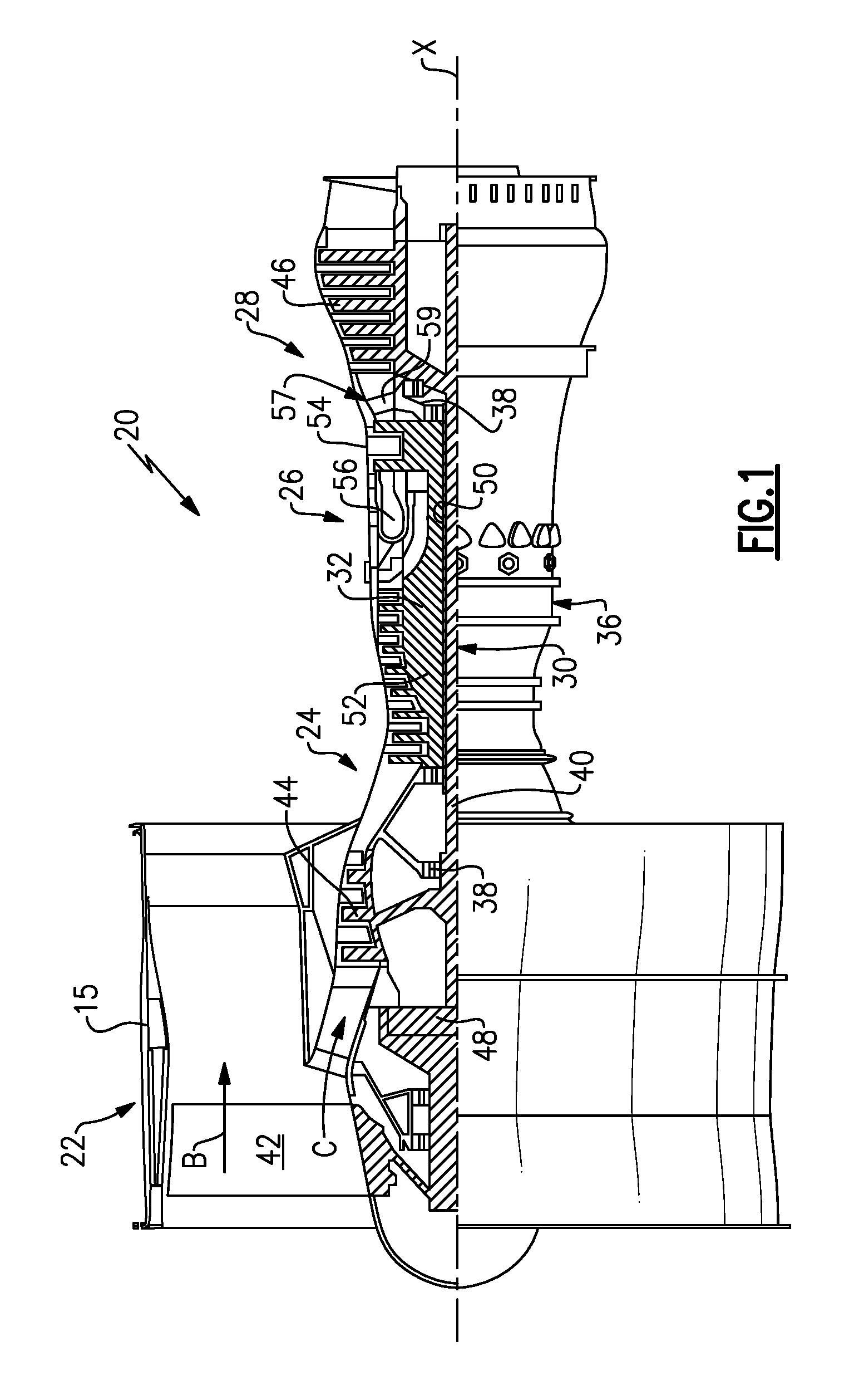
FIG. 1 schematically illustrates a gas turbine engine embodiment.
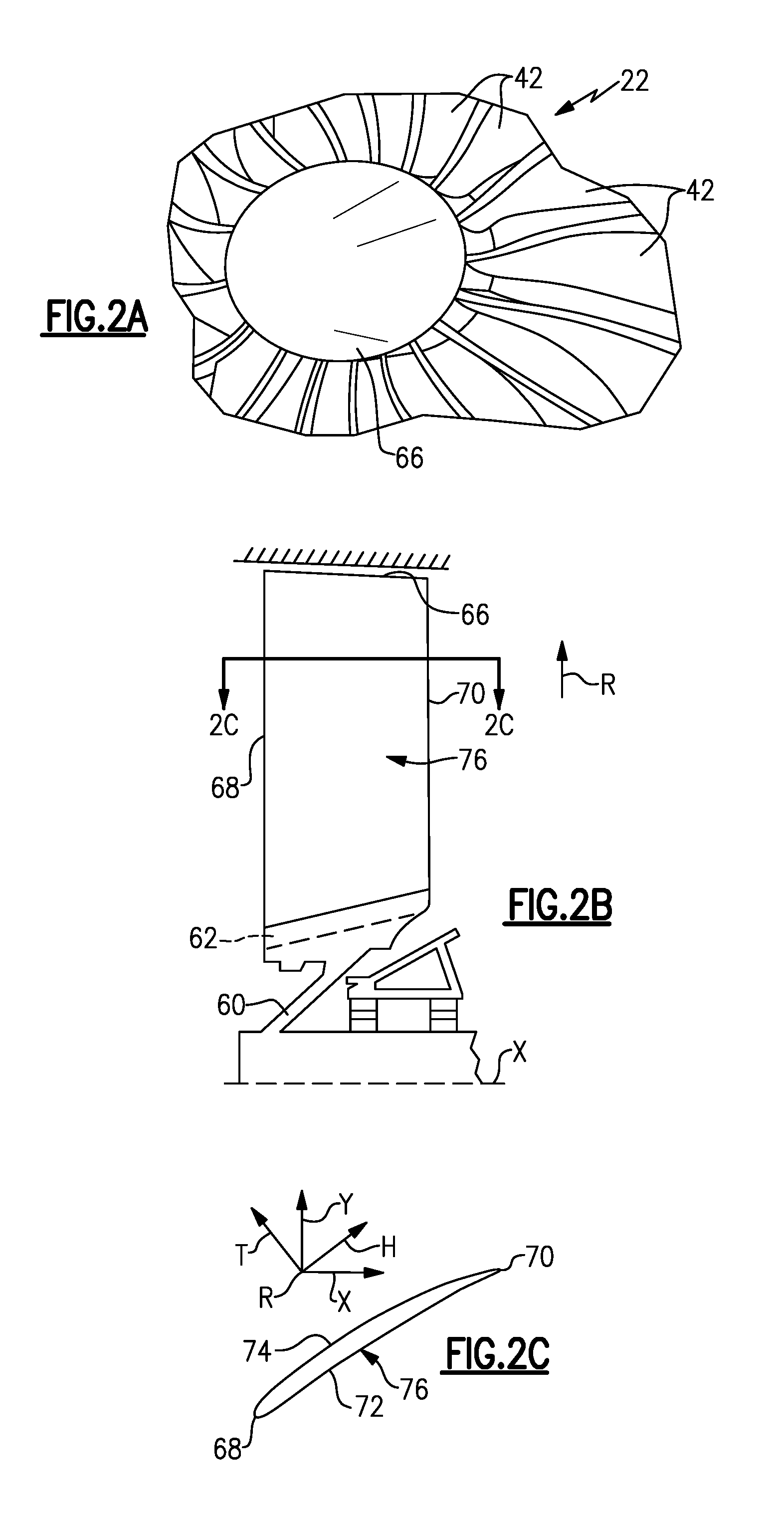
FIG. 2A is a perspective view of a portion of a fan section.
FIG. 2B is a schematic cross-sectional view of the fan section.
FIG. 2C is a cross-sectional view a fan blade taken along line 2C-2C in FIG. 2B.
FIG. 3A is a schematic view of fan blade span positions for an airfoil without any curvature at the leading and trailing edges.
FIG. 3B is an elevational view of a fan blade airfoil illustrating velocity vectors in relation to the leading and trailing edges.
FIG. 3C is a schematic perspective view of an airfoil fragment illustrating the definition of a leading edge sweep angle.
FIG. 3D is a schematic perspective view of an airfoil fragment illustrating the definition of a trailing edge sweep angle.
FIG. 4 is a schematic representation of a dihedral angle for an airfoil.
FIG. 5A graphically illustrates a leading edge sweep angle relative to a span position for a set of first example airfoils and a prior art airfoil.
FIG. 5B graphically illustrates a trailing edge sweep angle relative to a span position for a set of first example airfoils and a prior art airfoil.
FIG. 6A graphically illustrates a leading edge sweep angle relative to a span position for a set of second example airfoils and the prior art airfoil.
FIG. 6B graphically illustrates a trailing edge sweep angle relative to a span position for a set of second example airfoils and the prior art airfoil.
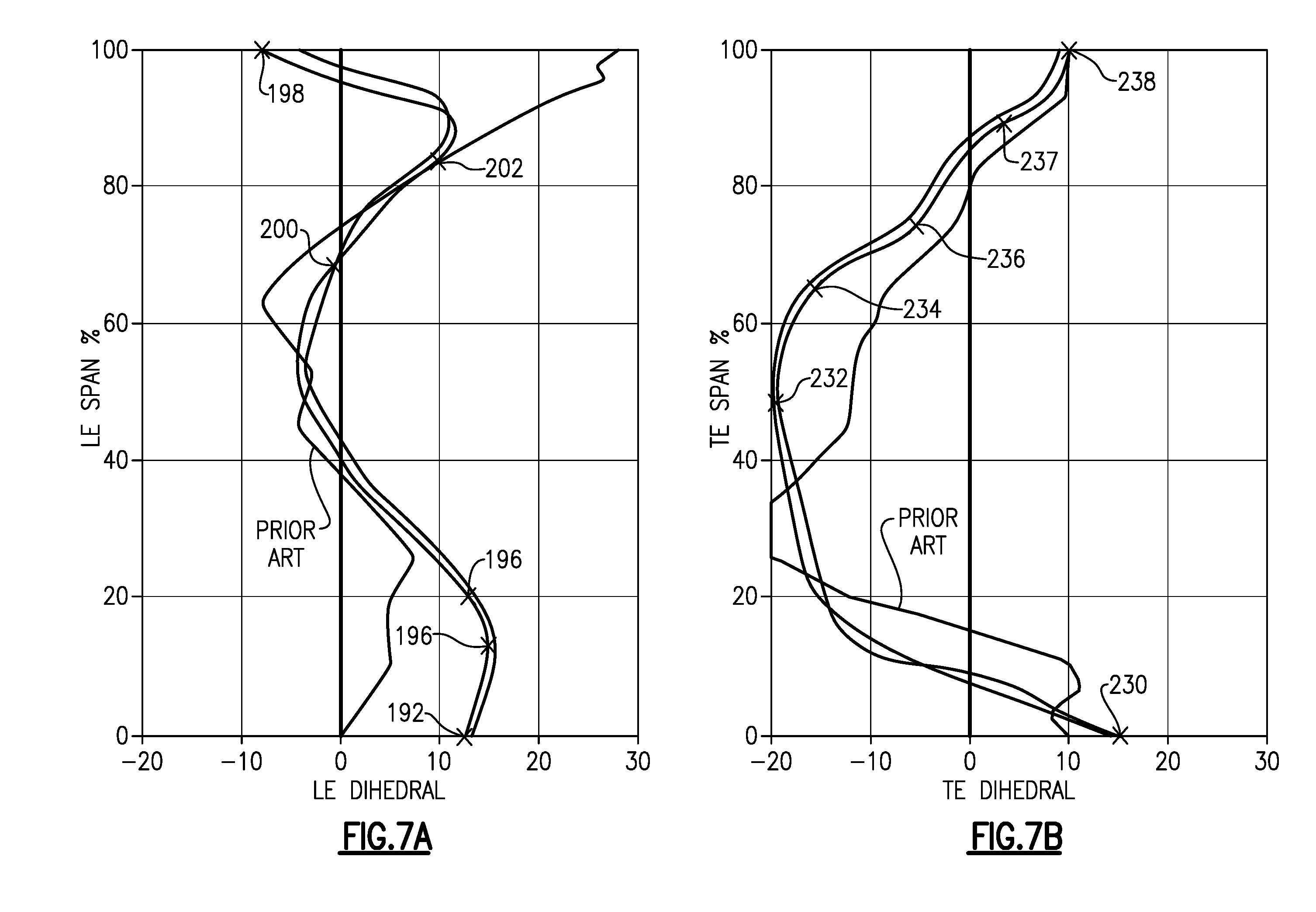
FIG. 7A illustrates a relationship between a leading edge aerodynamic dihedral angle and a span position for the set of first example airfoils and a prior art curve.
FIG. 7B illustrates a relationship between a trailing edge aerodynamic dihedral angle and a span position for the set of first example airfoils and a prior art curve.
FIG. 8A illustrates a relationship between a leading edge aerodynamic dihedral angle and a span position for the set of second example airfoils and the prior art curve.
FIG. 8B illustrates a relationship between a trailing edge aerodynamic dihedral angle and a span position for the set of second example airfoils and the prior art curve.
The embodiments, examples and alternatives of the preceding paragraphs, the claims, or the following description and drawings, including any of their various aspects or respective individual features, may be taken independently or in any combination. Features described in connection with one embodiment are applicable to all embodiments, unless such features are incompatible.
DETAILED DESCRIPTION
FIG. 1 schematically illustrates a gas turbine engine 20. The gas turbine engine 20 is disclosed herein as a two-spool turbofan that generally incorporates a fan section 22, a compressor section 24, a combustor section 26 and a turbine section 28. Alternative engines might include an augmenter section (not shown) among other systems or features. The fan section 22 drives air along a bypass flow path B in a bypass duct defined within a nacelle 15, while the compressor section 24 drives air along a core flow path C for compression and communication into the combustor section 26 then expansion through the turbine section 28. Although depicted as a two-spool turbofan gas turbine engine in the disclosed non-limiting embodiment, it should be understood that the concepts described herein are not limited to use with two-spool turbofans as the teachings may be applied to other types of turbine engines including three-spool architectures. That is, the disclosed airfoils may be used for engine configurations such as, for example, direct fan drives, or two- or three-spool engines with a speed change mechanism coupling the fan with a compressor or a turbine sections.
The exemplary engine 20 generally includes a low speed spool 30 and a high speed spool 32 mounted for rotation about an engine central longitudinal axis X relative to an engine static structure 36 via several bearing systems 38. It should be understood that various bearing systems 38 at various locations may alternatively or additionally be provided, and the location of bearing systems 38 may be varied as appropriate to the application.
The low speed spool 30 generally includes an inner shaft 40 that interconnects a fan 42, a first (or low) pressure compressor 44 and a first (or low) pressure turbine 46. The inner shaft 40 is connected to the fan 42 through a speed change mechanism, which in exemplary gas turbine engine 20 is illustrated as a geared architecture 48 to drive the fan 42 at a lower speed than the low speed spool 30. The high speed spool 32 includes an outer shaft 50 that interconnects a second (or high) pressure compressor 52 and a second (or high) pressure turbine 54. A combustor 56 is arranged in exemplary gas turbine 20 between the high pressure compressor 52 and the high pressure turbine 54. A mid-turbine frame 57 of the engine static structure 36 is arranged generally between the high pressure turbine 54 and the low pressure turbine 46. The mid-turbine frame 57 further supports bearing systems 38 in the turbine section 28. The inner shaft 40 and the outer shaft 50 are concentric and rotate via bearing systems 38 about the engine central longitudinal axis X which is collinear with their longitudinal axes.
The core airflow is compressed by the low pressure compressor 44 then the high pressure compressor 52, mixed and burned with fuel in the combustor 56, then expanded over the high pressure turbine 54 and low pressure turbine 46. The mid-turbine frame 57 includes airfoils 59 which are in the core airflow path C. The turbines 46, 54 rotationally drive the respective low speed spool 30 and high speed spool 32 in response to the expansion. It will be appreciated that each of the positions of the fan section 22, compressor section 24, combustor section 26, turbine section 28, and fan drive gear system 48 may be varied. For example, gear system 48 may be located aft of combustor section 26 or even aft of turbine section 28, and fan section 22 may be positioned forward or aft of the location of gear system 48.
The engine 20 in one example is a high-bypass geared aircraft engine. In a further example, the engine 20 bypass ratio is greater than about six (6), with an example embodiment being greater than about ten (10), the geared architecture 48 is an epicyclic gear train, such as a planetary gear system or other gear system, with a gear reduction ratio of greater than about 2.3 and the low pressure turbine 46 has a pressure ratio that is greater than about five. In one disclosed embodiment, the engine 20 bypass ratio is greater than about ten (10:1), the fan diameter is significantly larger than that of the low pressure compressor 44, and the low pressure turbine 46 has a pressure ratio that is greater than about five (5:1). Low pressure turbine 46 pressure ratio is pressure measured prior to inlet of low pressure turbine 46 as related to the pressure at the outlet of the low pressure turbine 46 prior to an exhaust nozzle. The geared architecture 48 may be an epicyclic gear train, such as a planetary gear system or other gear system, with a gear reduction ratio of greater than about 2.3:1. It should be understood, however, that the above parameters are only exemplary of one embodiment of a geared architecture engine and that the present invention is applicable to other gas turbine engines including direct drive turbofans.
The example gas turbine engine includes the fan 42 that comprises in one non-limiting embodiment less than about twenty-six (26) fan blades. In another non-limiting embodiment, the fan section 22 includes less than about twenty (20) fan blades. Moreover, in one disclosed embodiment the low pressure turbine 46 includes no more than about six (6) turbine rotors schematically indicated at 34. In another non-limiting example embodiment the low pressure turbine 46 includes about three (3) turbine rotors. A ratio between the number of fan blades 42 and the number of low pressure turbine rotors is between about 3.3 and about 8.6. The example low pressure turbine 46 provides the driving power to rotate the fan section 22 and therefore the relationship between the number of turbine rotors 34 in the low pressure turbine 46 and the number of blades 42 in the fan section 22 disclose an example gas turbine engine 20 with increased power transfer efficiency.
A significant amount of thrust is provided by the bypass flow B due to the high bypass ratio. The fan section 22 of the engine 20 is designed for a particular flight condition--typically cruise at about 0.8 Mach and about 35,000 feet. The flight condition of 0.8 Mach and 35,000 ft, with the engine at its best fuel consumption--also known as "bucket cruise Thrust Specific Fuel Consumption (`TSFCT`)"--is the industry standard parameter of lbm of fuel being burned divided by lbf of thrust the engine produces at that minimum point. "Low fan pressure ratio" is the pressure ratio across the fan blade alone, without a Fan Exit Guide Vane ("FEGV") system. The low fan pressure ratio as disclosed herein according to one non-limiting embodiment is less than about 1.55. In another non-limiting embodiment the low fan pressure ratio is less than about 1.45. In another non-limiting embodiment the low fan pressure ratio is from 1.1 to 1.45. "Low corrected fan tip speed" is the actual fan tip speed in ft/sec divided by an industry standard temperature correction of [(Tram.degree. R)/(518.7.degree. R)].sup.0.5. The "low corrected fan tip speed" as disclosed herein according to another non-limiting embodiment is less than about 1200 ft/second.
Referring to FIG. 2A-2C, the fan blade 42 is supported by a fan hub 60 that is rotatable about the axis X. Each fan blade 42 includes an airfoil 64 extending in a radial span direction R from a root 62 to a tip 66. A 0% span position corresponds to a section of the airfoil 64 at the inner flow path (e.g., a platform), and a 100% span position corresponds to a section of the airfoil 64 at the tip 66.
The root 62 is received in a correspondingly shaped slot in the fan hub 60. The airfoil 64 extends radially outward of the platform, which provides the inner flow path. The platform may be integral with the fan blade or separately secured to the fan hub, for example. A spinner 66 is supported relative to the fan hub 60 to provide an aerodynamic inner flow path into the fan section 22.
The airfoil 64 has an exterior surface 76 providing a contour that extends from a leading edge 68 aftward in a chord-wise direction H to a trailing edge 70, as shown in FIG. 2C. Pressure and suction sides 72, 74 join one another at the leading and trailing edges 68, 70 and are spaced apart from one another in an airfoil thickness direction T. An array of the fan blades 42 are positioned about the axis X in a circumferential or tangential direction Y. Any suitable number of fan blades may be used in a given application.
The exterior surface 76 of the airfoil 64 generates lift based upon its geometry and directs flow along the core flow path C. The fan blade 42 may be constructed from a composite material, or an aluminum alloy or titanium alloy, or a combination of one or more of these. Abrasion-resistant coatings or other protective coatings may be applied to the fan blade 42. The curves and associated values assume a fan in a hot, running condition (typically cruise).
One characteristic of fan blade performance relates to the fan blade's leading and trailing edge sweep angles relative to a particular span position (R direction). Referring to FIG. 3A, span positions a schematically illustrated from 0% to 100% in 10% increments. Each section at a given span position is provided by a conical cut that corresponds to the shape of the core flow path, as shown by the large dashed lines. In the case of a fan blade with an integral platform, the 0% span position corresponds to the radially innermost location where the airfoil meets the fillet joining the airfoil to the platform. In the case of a fan blade without an integral platform, the 0% span position corresponds to the radially innermost location where the discrete platform meets the exterior surface of the airfoil. In addition to varying with span, leading and trailing edge sweep varies between a hot, running condition and a cold, static ("on the bench") condition.
The axial velocity Vx (FIG. 3B) of the core flow C is substantially constant across the radius of the flowpath. However the linear velocity U of a rotating airfoil increases with increasing radius. Accordingly, the relative velocity Vr of the working medium at the airfoil leading edge increases with increasing radius, and at high enough rotational speeds, the airfoil experiences supersonic working medium flow velocities in the vicinity of its tip. The relative velocity at the leading edge 68 is indicated as Vr.sub.LE, and the relative velocity at the trailing edge 70 is indicated as Vr.sub.TE.
Supersonic flow over an airfoil, while beneficial for maximizing the pressurization of the working medium, has the undesirable effect of reducing fan efficiency by introducing losses in the working medium's total pressure. Therefore, it is typical to sweep the airfoil's leading edge over at least a portion of the blade span so that the working medium velocity component in the chordwise direction (perpendicular to the leading edge) is subsonic. Since the relative velocity Vr increases with increasing radius, the sweep angle typically increases with increasing radius as well. As shown in FIGS. 3C and 3D, the sweep angle .sigma. at any arbitrary radius Rd (FIG. 3A) at the leading edge 68 is indicated as .sigma..sub.LE, and at the trailing edge 70, .sigma..sub.TE.
Referring to FIG. 3C, the leading edge sweep angle .sigma..sub.LE is the acute angle between a line 90 tangent to the leading edge 68 of the airfoil 64 and a plane 92 perpendicular to the relative velocity vector Vr.sub.LE. The sweep angle is measured in plane 94, which contains both the relative velocity vector Vr.sub.LE and the tangent line 90 and is perpendicular to plane 92. FIGS. 5A and 6A are provided in conformance with this definition of the leading edge sweep angle .sigma..sub.LE.
Referring to FIG. 3D, the trailing edge sweep angle .sigma..sub.TE is the acute angle between a line 96 tangent to the trailing edge 70 of the airfoil 64 and a plane 98 perpendicular to the relative velocity vector Vr.sub.TE. The sweep angle is measured in plane 100, which contains both the relative velocity vector Vr.sub.TE and the tangent line 96 and is perpendicular to plane 98. FIGS. 5B and 6B are provided in conformance with this definition of the trailing edge sweep angle .sigma..sub.TE.
Thus, a negative sweep angle indicates an airfoil edge locally oriented in a direction opposite the velocity vector (Vr.sub.LE or Vr.sub.TE), and a positive sweep angle indicates an airfoil edge locally oriented in the same direction as the velocity vector.
An aerodynamic dihedral angle D (simply referred to as "dihedral") is schematically illustrated in FIG. 4 for a simple airfoil. An axisymmetric stream surface S passes through the airfoil 64 at a location that corresponds to a span location (FIG. 3A). For the sake of simplicity, the dihedral D relates to the angle at which a line L along the leading or trailing edge tilts with respect to the stream surface S. A plane P is normal to the line L and forms an angle with the tangential direction Y, providing the dihedral D. A positive dihedral D corresponds to the line tilting toward the suction side (suction side-leaning), and a negative dihedral D corresponds to the line tilting toward the pressure side (pressure side-leaning). The method of determining and calculating the dihedral for more complex airfoil geometries is disclosed in Smith Jr., Leroy H., and Yeh, Hsuan "Sweep and Dihedral Effects in Axial-Flow Turbomachinery." J. Basic Eng. Vol. 85 Iss. 3, pp. 401-414 (Sep 01, 1963), which is incorporated by reference in its entirety. Leading and trailing edge dihedral, like sweep, varies between a hot, running condition and a cold, static ("on the bench") condition.
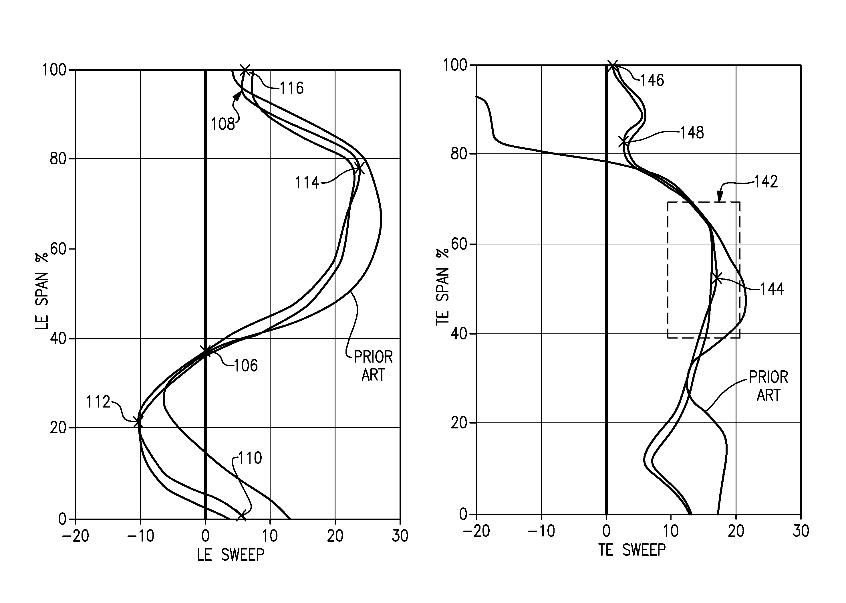
Several example fan blades are shown in each of the graphs in FIGS. 5A-6B, each blade represented by a curve. Only one curve in each graph is discussed for simplicity. Referring to FIGS. 5A and 6A, the airfoil has a curve corresponding to a relationship between a leading edge sweep angle (LE SWEEP) and a span position (LE SPAN %). The curves illustrate that a leading edge sweep angle at the 100% span position (116 in FIG. 5A; 128 in FIG. 6A) is less negative than a forward-most leading edge sweep angle (112 in FIG. 5A; 124 in FIG. 6A) along the curve. The curves have a decreasing leading edge sweep angle rate (108 in FIG. 5A; 118 in FIG. 6A) in a range of a 80-100% span position. That is, the sweep angle is not constant, but changes. This change, or leading edge sweep angle rate, decreases in the range of 80-100% span.
The curves have a portion extending span-wise toward the tip and from the forward-most leading edge sweep angle (112 in FIG. 5A; 124 in FIG. 6A). The forward-most leading edge sweep angle is in a range of -10.degree. to -15.degree.. In the examples shown in FIGS. 5A and 6A, the forward-most leading edge sweep angle is about -10.degree.. The portion has a decreasing leading edge sweep angle that crosses a zero sweep angle (106 in FIG. 5A; 120 in FIG. 6A) in the range of a 30-40% span position.
A rearward-most leading edge sweep angle (114 in FIG. 5A; 126 in FIG. 6A) is in a range of 15.degree. to 30.degree.. In the example shown in FIG. 5A, the rearward-most leading edge sweep angle 114 is in a range of 75-85% span position. With continuing reference to FIG. 5A, a leading edge sweep angle 110 at the 0% span position and the leading edge sweep angle 116 at the 100% span position are within 5.degree. of one another. Both the leading edge sweep angle at the 0% span position and the leading edge sweep angle at the 100% span position are positive.
Referring to FIG. 6A, a leading edge sweep angle 122 at the 0% span position is negative, and a leading edge sweep angle 128 at the 100% span position is positive. The leading edge sweep angle 128 at the 0% span position and the leading edge sweep angle 128 at the 100% span position are within 10.degree. of one another.
Trailing edge sweep angles are graphically illustrated in FIGS. 5B and 6B. The airfoil has curves corresponding to a relationship between a trailing edge sweep angle and the span position. Within a region of the curve (142 in FIG. 5B; 150 in FIG. 6B), the trailing edge sweep angle (TE SWEEP) is in a range of 10.degree. to 20.degree. in a range of 40-70% span position (TE SPAN %). The trailing edge sweep angle is positive from 0% span to at least 95% span. In one example, the trailing edge sweep angle is in a range of 10.degree. to 20.degree. in a range of 50-70% span position, and in another example, the trailing edge sweep angle is in a range of 10.degree. to 20.degree. in a range of 60-70% span position. Within the 60-70% span position, the trailing edge sweep angle is about 15.degree.. In the examples, a positive-most trailing edge sweep angle (144 in FIG. 5B; 152 in FIG. 6B) is within the range of 10.degree. to 20.degree. in the range of 40-70% span position.
Referring to FIG. 5B, the trailing edge sweep angle is positive from 0%-95% span. The trailing edge sweep angle 146 at the 100% span position is about zero, but negative. The trailing edge sweep angle transitions from less positive to more positive at greater than an 80% span position at point 148. The positive-most trailing edge sweep angle 144 is at a greater than 50% span position.
Referring to FIG. 5B, a trailing edge sweep angle 154 at the 0% span position and a trailing edge sweep angle 156 at the 100% span position are about the same. The positive-most trailing edge sweep angle 152 is at about a 70% span position.
The leading and trailing edge sweep in a hot, running condition along the span of the airfoils 64 relate to the contour of the airfoil and provide necessary fan operation in cruise at the lower, preferential speeds enabled by the geared architecture 48 in order to enhance aerodynamic functionality and thermal efficiency. As used herein, the hot, running condition is the condition during cruise of the gas turbine engine 20. For example, the leading and trailing edge sweep in the hot, running condition can be determined in a known manner using numerical analysis, such as finite element analysis. Example relationships between the leading edge dihedral (LE DIHEDRAL) and the span position (LE SPAN %) are shown in FIGS. 7A and 8A for several example fan blades, each represented by a curve. Only one curve in each graph is discussed for simplicity. In the examples, the leading edge dihedral is negative from the 0% span position to the 100% span position.
The leading edge dihedral at the 0% span position (192 in FIG. 7A; 204 in FIG. 8A) is in the range of -3.degree. to -12.degree.. In the examples shown in FIGS. 7A and 8A, the leading edge dihedral at the 0% span position is about -4.degree. .
The leading edge dihedral extends from the 0% span position to a 20% span position (196 in FIG. 7A; 208 in FIG. 8A) having a leading edge dihedral in a range of -2.degree. to -6.degree..
In the examples shown in FIGS. 7A and 8A, the leading edge dihedral includes a first point (200 in FIG. 7A; 210 in FIG. 8A) at a 75% span position and extends generally linearly from the first point to a second point (202 in FIG. 7A; 214 in FIG. 8A) at the 85% span position. The first point is in a range of -8.degree. to -10.degree. dihedral, and the second point is in a range of -3.degree. to -6.degree. dihedral.
Referring to FIG. 7A, a maximum negative dihedral 198 is in a range of 95-100% span position. A least negative dihedral 194 is in a range of 5-15% span position. Referring to FIG. 8A, a maximum negative dihedral 210 is in a range of 65-75% span position. A least negative dihedral 206 is in a range of 0-10% span position.
Example relationships between the trailing edge dihedral and the span position are shown in FIGS. 7B and 8B for several example fan blades, each represented by a curve. Only one curve in each graph is discussed for simplicity. In the examples, the trailing edge dihedral is positive from the 0% span position to the 100% span position. The relationship provides a generally C-shaped curve from the 0% span position to a 50% span position and then a 90% span position.
A trailing edge dihedral (230 in FIG. 7B; 240 in FIG. 8B) at the 0% span position is in a range of 20.degree. to 25.degree.. A trailing edge dihedral (232 in FIG. 7B; 242 in FIG. 8B) at about the 50% span position is in a range of 2.degree. to 6.degree.. A trailing edge dihedral (237 in FIG. 7B; 247 in FIG. 8B) at the 90% span position is in a range of 16.degree. to 22.degree.. From a 65% span position (234 in FIG. 7B; 244 in FIG. 8B) to a 75% span position (236 in FIG. 7B; 246 in FIG. 8B) the trailing edge dihedral increases about 5.degree..
A positive-most trailing edge dihedral (238 in FIG. 7B; 248 in FIG. 8B) in a 80%-100% span position is within 5.degree. of the trailing edge dihedral in the 0% span position (230 in FIG. 7B; 240 in FIG. 8B). A least positive trailing edge dihedral (232 in FIG. 7B; 242 in FIG. 8B) is in a 40%-55% span position.
The leading and trailing edge aerodynamic dihedral angle in a hot, running condition along the span of the airfoils 64 relate to the contour of the airfoil and provide necessary fan operation in cruise at the lower, preferential speeds enabled by the geared architecture 48 in order to enhance aerodynamic functionality and thermal efficiency. As used herein, the hot, running condition is the condition during cruise of the gas turbine engine 20. For example, the leading and trailing edge aerodynamic dihedral angle in the hot, running condition can be determined in a known manner using numerical analysis, such as finite element analysis. It should also be understood that although a particular component arrangement is disclosed in the illustrated embodiment, other arrangements will benefit herefrom. Although particular step sequences are shown, described, and claimed, it should be understood that steps may be performed in any order, separated or combined unless otherwise indicated and will still benefit from the present invention.
Although the different examples have specific components shown in the illustrations, embodiments of this invention are not limited to those particular combinations. It is possible to use some of the components or features from one of the examples in combination with features or components from another one of the examples.
Although an example embodiment has been disclosed, a worker of ordinary skill in this art would recognize that certain modifications would come within the scope of the claims. For that reason, the following claims should be studied to determine their true scope and content.
* * * * *
References
-
cgabusinessdesk.com/document/aviation_tech_review.pdf
-
catalog.wshampshire.com/Asset/psg_teflon_ptfe.pdf
-
bloomberg.com/news/articles/2016-06-30/ge-wins-shot-to-invalidate-pratt-airplane-engine-patent-in-u-s
-
enginealliance.com/engine_specifications.html
-
mmsonline.com/articles/composite-fan-blade-containment-casepp
-
pyrografproducts.com/Merchant5/merchant.mvc?Screen=cp_nanofiber
D00000
D00001
D00002
D00003
D00004
D00005
D00006
D00007
D00008
D00009
XML
uspto.report is an independent third-party trademark research tool that is not affiliated, endorsed, or sponsored by the United States Patent and Trademark Office (USPTO) or any other governmental organization. The information provided by uspto.report is based on publicly available data at the time of writing and is intended for informational purposes only.
While we strive to provide accurate and up-to-date information, we do not guarantee the accuracy, completeness, reliability, or suitability of the information displayed on this site. The use of this site is at your own risk. Any reliance you place on such information is therefore strictly at your own risk.
All official trademark data, including owner information, should be verified by visiting the official USPTO website at www.uspto.gov. This site is not intended to replace professional legal advice and should not be used as a substitute for consulting with a legal professional who is knowledgeable about trademark law.