Genset for top drive unit
Thiemann , et al.
U.S. patent number 10,309,166 [Application Number 15/258,752] was granted by the patent office on 2019-06-04 for genset for top drive unit. This patent grant is currently assigned to WEATHERFORD TECHNOLOGY HOLDINGS, LLC. The grantee listed for this patent is Weatherford Technology Holdings, LLC. Invention is credited to Christina Karin Hebebrand, Martin Liess, John Fielding Ownby, Bjoern Thiemann, Frank Wern, Aicam Zouhair.


View All Diagrams
| United States Patent | 10,309,166 |
| Thiemann , et al. | June 4, 2019 |
Genset for top drive unit
Abstract
A system includes an accessory tool selected from a group consisting of a casing unit, a cementing unit, and a drilling unit; and a genset mounted to the accessory tool and comprising: a fluid driven motor having an inlet and an outlet for connection to a control swivel of the system; an electric generator connected to the fluid driven motor; a manifold having an inlet for connection to the control swivel and an outlet connected an accessory tool actuator; and a control unit in communication with the electric generator and the manifold and comprising a wireless data link.
| Inventors: | Thiemann; Bjoern (Burgwedel, DE), Wern; Frank (Hannover, DE), Ownby; John Fielding (Houston, TX), Zouhair; Aicam (Houston, TX), Liess; Martin (Seelze, DE), Hebebrand; Christina Karin (Hannover, DE) | ||||||||||
|---|---|---|---|---|---|---|---|---|---|---|---|
| Applicant: |
|
||||||||||
| Assignee: | WEATHERFORD TECHNOLOGY HOLDINGS,
LLC (Houston, TX) |
||||||||||
| Family ID: | 56940427 | ||||||||||
| Appl. No.: | 15/258,752 | ||||||||||
| Filed: | September 7, 2016 |
Prior Publication Data
| Document Identifier | Publication Date | |
|---|---|---|
| US 20170067303 A1 | Mar 9, 2017 | |
Related U.S. Patent Documents
| Application Number | Filing Date | Patent Number | Issue Date | ||
|---|---|---|---|---|---|
| 62215503 | Sep 8, 2015 | ||||
| Current U.S. Class: | 1/1 |
| Current CPC Class: | E21B 19/06 (20130101); E21B 33/05 (20130101); E21B 19/16 (20130101); F01C 21/008 (20130101); E21B 19/14 (20130101); F01C 21/18 (20130101); F01C 13/00 (20130101); E21B 3/02 (20130101); E21B 33/14 (20130101); F01C 1/103 (20130101); E21B 33/068 (20130101) |
| Current International Class: | E21B 19/06 (20060101); F01C 1/10 (20060101); E21B 33/068 (20060101); E21B 33/05 (20060101); E21B 19/14 (20060101); F01C 13/00 (20060101); E21B 19/16 (20060101); E21B 3/02 (20060101); E21B 33/14 (20060101); F01C 21/00 (20060101); F01C 21/18 (20060101) |
References Cited [Referenced By]
U.S. Patent Documents
| 1367156 | February 1921 | McAlvay et al. |
| 1610977 | December 1926 | Scott |
| 1822444 | September 1931 | MacClatchie |
| 2370354 | February 1945 | Hurst |
| 3147992 | September 1964 | Haeber et al. |
| 3354951 | November 1967 | Savage et al. |
| 3385370 | May 1968 | Knox et al. |
| 3662842 | May 1972 | Bromell |
| 3698426 | October 1972 | Litchfield et al. |
| 3747675 | July 1973 | Brown |
| 3766991 | October 1973 | Brown |
| 3776320 | December 1973 | Brown |
| 3842619 | October 1974 | Bychurch, Sr. |
| 3888318 | June 1975 | Brown |
| 3899024 | August 1975 | Tonnelli et al. |
| 3913687 | October 1975 | Gyongyosi et al. |
| 3915244 | October 1975 | Brown |
| 3964552 | June 1976 | Slator |
| 4022284 | May 1977 | Crow |
| 4051587 | October 1977 | Boyadjieff |
| 4100968 | July 1978 | Delano |
| 4192155 | March 1980 | Gray |
| 4199847 | April 1980 | Owens |
| 4235469 | November 1980 | Denny et al. |
| 4364407 | December 1982 | Hilliard |
| 4377179 | March 1983 | Giebeler |
| 4402239 | September 1983 | Mooney |
| 4449596 | May 1984 | Boyadjieff |
| 4478244 | October 1984 | Garrett |
| 4497224 | February 1985 | Jurgens |
| 4593773 | June 1986 | Skeie |
| 4762187 | August 1988 | Haney |
| 4776617 | October 1988 | Sato |
| 4779688 | October 1988 | Baugh |
| 4791997 | December 1988 | Krasnov |
| 4813493 | March 1989 | Shaw et al. |
| 4815546 | March 1989 | Haney et al. |
| 4821814 | April 1989 | Willis et al. |
| 4844181 | July 1989 | Bassinger |
| 4867236 | September 1989 | Haney et al. |
| 4955949 | September 1990 | Bailey et al. |
| 4962819 | October 1990 | Bailey et al. |
| 4972741 | November 1990 | Sibille |
| 4981180 | January 1991 | Price |
| 4997042 | March 1991 | Jordan et al. |
| 5036927 | August 1991 | Willis |
| 5099725 | March 1992 | Bouligny, Jr. et al. |
| 5152554 | October 1992 | LaFleur et al. |
| 5172940 | December 1992 | Usui et al. |
| 5191939 | March 1993 | Stokley |
| 5215153 | June 1993 | Younes |
| 5245877 | September 1993 | Ruark |
| 5282653 | February 1994 | LaFleur et al. |
| 5297833 | March 1994 | Willis et al. |
| 5348351 | September 1994 | LaFleur et al. |
| 5385514 | January 1995 | Dawe |
| 5433279 | July 1995 | Tessari et al. |
| 5441310 | August 1995 | Barrett et al. |
| 5456320 | October 1995 | Baker |
| 5479988 | January 1996 | Appleton |
| 5486223 | January 1996 | Carden |
| 5501280 | March 1996 | Brisco |
| 5509442 | April 1996 | Claycomb |
| 5577566 | November 1996 | Albright et al. |
| 5584343 | December 1996 | Coone |
| 5645131 | July 1997 | Trevisani |
| 5664310 | September 1997 | Penisson |
| 5682952 | November 1997 | Stokley |
| 5735348 | April 1998 | Hawkins, III |
| 5778742 | July 1998 | Stuart |
| 5839330 | November 1998 | Stokka |
| 5909768 | June 1999 | Castille et al. |
| 5918673 | July 1999 | Hawkins et al. |
| 5950724 | September 1999 | Giebeler |
| 5971079 | October 1999 | Mullins |
| 5992520 | November 1999 | Schultz et al. |
| 6003412 | December 1999 | Dlask et al. |
| 6053191 | April 2000 | Hussey |
| 6102116 | August 2000 | Giovanni |
| 6142545 | November 2000 | Penman et al. |
| 6161617 | December 2000 | Gjedebo |
| 6173777 | January 2001 | Mullins |
| 6276450 | August 2001 | Seneviratne |
| 6279654 | August 2001 | Mosing et al. |
| 6289911 | September 2001 | Majkovic |
| 6309002 | October 2001 | Bouligny |
| 6311792 | November 2001 | Scott et al. |
| 6328343 | December 2001 | Hosie et al. |
| 6378630 | April 2002 | Ritorto et al. |
| 6390190 | May 2002 | Mullins |
| 6401811 | June 2002 | Coone |
| 6415862 | July 2002 | Mullins |
| 6431626 | August 2002 | Bouligny |
| 6443241 | September 2002 | Juhasz et al. |
| 6460620 | October 2002 | LaFleur |
| 6527047 | March 2003 | Pietras |
| 6536520 | March 2003 | Snider et al. |
| 6571876 | June 2003 | Szarka |
| 6578632 | June 2003 | Mullins |
| 6595288 | July 2003 | Mosing et al. |
| 6604578 | August 2003 | Mullins |
| 6622796 | September 2003 | Pietras |
| 6637526 | October 2003 | Juhasz et al. |
| 6640824 | November 2003 | Majkovic |
| 6666273 | December 2003 | Laurel |
| 6675889 | January 2004 | Mullins et al. |
| 6679333 | January 2004 | York et al. |
| 6688398 | February 2004 | Pietras |
| 6691801 | February 2004 | Juhasz et al. |
| 6705405 | March 2004 | Pietras |
| 6715542 | April 2004 | Mullins |
| 6719046 | April 2004 | Mullins |
| 6722425 | April 2004 | Mullins |
| 6725938 | April 2004 | Pietras |
| 6732819 | May 2004 | Wenzel |
| 6732822 | May 2004 | Slack et al. |
| 6742584 | June 2004 | Appleton |
| 6742596 | June 2004 | Haugen |
| 6779599 | August 2004 | Mullins et al. |
| 6832656 | December 2004 | Fournier, Jr. et al. |
| 6883605 | April 2005 | Arceneaux et al. |
| 6892835 | May 2005 | Shahin et al. |
| 6908121 | June 2005 | Hirth et al. |
| 6925807 | August 2005 | Jones et al. |
| 6938697 | September 2005 | Haugen |
| 6976298 | December 2005 | Pietras |
| 6994176 | February 2006 | Shahin et al. |
| 7000503 | February 2006 | Dagenais et al. |
| 7001065 | February 2006 | Dishaw et al. |
| 7004259 | February 2006 | Pietras |
| 7007753 | March 2006 | Robichaux et al. |
| 7017671 | March 2006 | Williford |
| 7021374 | April 2006 | Pietras |
| 7025130 | April 2006 | Bailey et al. |
| 7073598 | July 2006 | Haugen |
| 7090021 | August 2006 | Pietras |
| 7096948 | August 2006 | Mosing et al. |
| 7114235 | October 2006 | Jansch et al. |
| 7128161 | October 2006 | Pietras |
| 7137454 | November 2006 | Pietras |
| 7140443 | November 2006 | Beierbach et al. |
| 7143849 | December 2006 | Shahin et al. |
| 7147254 | December 2006 | Niven et al. |
| 7159654 | January 2007 | Ellison et al. |
| 7178612 | February 2007 | Belik |
| 7213656 | May 2007 | Pietras |
| 7219744 | May 2007 | Pietras |
| 7231969 | June 2007 | Folk et al. |
| 7270189 | September 2007 | Brown et al. |
| 7281451 | October 2007 | Schulze Beckinghausen |
| 7281587 | October 2007 | Haugen |
| 7303022 | December 2007 | Tilton et al. |
| 7325610 | February 2008 | Giroux et al. |
| 7353880 | April 2008 | Pietras |
| 7448456 | November 2008 | Shahin et al. |
| 7451826 | November 2008 | Pietras |
| 7490677 | February 2009 | Buytaert et al. |
| 7503397 | March 2009 | Giroux et al. |
| 7509722 | March 2009 | Shahin et al. |
| 7513300 | April 2009 | Pietras et al. |
| 7591304 | September 2009 | Juhasz et al. |
| 7617866 | November 2009 | Pietras |
| 7635026 | December 2009 | Mosing et al. |
| 7665515 | February 2010 | Mullins |
| 7665530 | February 2010 | Wells et al. |
| 7665531 | February 2010 | Pietras |
| 7690422 | April 2010 | Swietlik et al. |
| 7694730 | April 2010 | Angman |
| 7694744 | April 2010 | Shahin |
| 7699121 | April 2010 | Juhasz et al. |
| 7712523 | May 2010 | Snider et al. |
| 7730698 | June 2010 | Montano et al. |
| 7757759 | July 2010 | Jahn et al. |
| 7779922 | August 2010 | Harris et al. |
| 7793719 | September 2010 | Snider et al. |
| 7817062 | October 2010 | Li et al. |
| 7828085 | November 2010 | Kuttel et al. |
| 7841415 | November 2010 | Winter |
| 7854265 | December 2010 | Zimmermann |
| 7866390 | January 2011 | Latiolais, Jr. et al. |
| 7874352 | January 2011 | Odell, II et al. |
| 7874361 | January 2011 | Mosing et al. |
| 7878237 | February 2011 | Angman |
| 7878254 | February 2011 | Abdollahi et al. |
| 7882902 | February 2011 | Boutwell, Jr. |
| 7896084 | March 2011 | Haugen |
| 7918273 | April 2011 | Snider et al. |
| 7958787 | June 2011 | Hunter |
| 7971637 | July 2011 | Duhon et al. |
| 7975768 | July 2011 | Fraser et al. |
| 8118106 | February 2012 | Wiens et al. |
| 8141642 | March 2012 | Olstad et al. |
| 8210268 | July 2012 | Heidecke et al. |
| 8281856 | October 2012 | Jahn et al. |
| 8307903 | November 2012 | Redlinger et al. |
| 8365834 | February 2013 | Liess et al. |
| 8459361 | June 2013 | Leuchtenberg |
| 8505984 | August 2013 | Henderson et al. |
| 8567512 | October 2013 | Odell, II et al. |
| 8601910 | December 2013 | Begnaud |
| 8636067 | January 2014 | Robichaux et al. |
| 8651175 | February 2014 | Fallen |
| 8668003 | March 2014 | Osmundsen et al. |
| 8708055 | April 2014 | Liess et al. |
| 8727021 | May 2014 | Heidecke et al. |
| 8776898 | July 2014 | Liess et al. |
| 8783339 | July 2014 | Sinclair et al. |
| 8839884 | September 2014 | Kuttel et al. |
| 8893772 | November 2014 | Henderson et al. |
| 9068406 | June 2015 | Clasen et al. |
| 9206851 | December 2015 | Slaughter, Jr. et al. |
| 9631438 | April 2017 | McKay |
| 2002/0043403 | April 2002 | Juhasz et al. |
| 2002/0074132 | June 2002 | Juhasz et al. |
| 2002/0084069 | July 2002 | Mosing et al. |
| 2002/0129934 | September 2002 | Mullins et al. |
| 2002/0170720 | November 2002 | Haugen |
| 2003/0098150 | May 2003 | Andreychuk |
| 2003/0107260 | June 2003 | Ording et al. |
| 2003/0221519 | December 2003 | Haugen |
| 2004/0003490 | January 2004 | Shahin et al. |
| 2004/0069497 | April 2004 | Jones et al. |
| 2004/0216924 | November 2004 | Pietras et al. |
| 2005/0000691 | January 2005 | Giroux et al. |
| 2005/0206163 | September 2005 | Guesnon et al. |
| 2005/0257933 | November 2005 | Pietras |
| 2005/0269072 | December 2005 | Folk et al. |
| 2005/0269104 | December 2005 | Folk et al. |
| 2005/0269105 | December 2005 | Pietras |
| 2005/0274508 | December 2005 | Folk |
| 2006/0037784 | February 2006 | Walter et al. |
| 2006/0124353 | June 2006 | Juhasz et al. |
| 2006/0151181 | July 2006 | Shahin |
| 2006/0180315 | August 2006 | Shahin et al. |
| 2007/0044973 | March 2007 | Fraser et al. |
| 2007/0074874 | April 2007 | Richardson |
| 2007/0102992 | May 2007 | Jager |
| 2007/0131416 | June 2007 | Odell, II et al. |
| 2007/0140801 | June 2007 | Kuttel et al. |
| 2007/0144730 | June 2007 | Shahin et al. |
| 2007/0158076 | July 2007 | Hollingsworth, Jr. et al. |
| 2007/0251699 | November 2007 | Neils et al. |
| 2007/0251701 | November 2007 | Jahn et al. |
| 2007/0257811 | November 2007 | Hall et al. |
| 2008/0059073 | March 2008 | Giroux et al. |
| 2008/0099196 | May 2008 | Latiolais et al. |
| 2008/0125876 | May 2008 | Boutwell |
| 2008/0202812 | August 2008 | Childers |
| 2008/0308281 | December 2008 | Boutwell, Jr. et al. |
| 2009/0151934 | June 2009 | Heidecke et al. |
| 2009/0159294 | June 2009 | Abdollahi et al. |
| 2009/0200038 | August 2009 | Swietlik et al. |
| 2009/0205820 | August 2009 | Koederitz et al. |
| 2009/0205827 | August 2009 | Swietlik et al. |
| 2009/0205836 | August 2009 | Swietlik et al. |
| 2009/0205837 | August 2009 | Swietlik et al. |
| 2009/0229837 | September 2009 | Wiens et al. |
| 2009/0266532 | October 2009 | Revheim et al. |
| 2009/0272537 | November 2009 | Alikin et al. |
| 2009/0274544 | November 2009 | Liess |
| 2009/0274545 | November 2009 | Liess et al. |
| 2009/0316528 | December 2009 | Ramshaw et al. |
| 2009/0321086 | December 2009 | Zimmermann |
| 2010/0032162 | February 2010 | Olstad et al. |
| 2010/0101805 | April 2010 | Angelle et al. |
| 2010/0200222 | August 2010 | Robichaux et al. |
| 2010/0206583 | August 2010 | Swietlik et al. |
| 2010/0206584 | August 2010 | Clubb et al. |
| 2010/0236777 | September 2010 | Partouche et al. |
| 2011/0036586 | February 2011 | Hart et al. |
| 2011/0039086 | February 2011 | Graham et al. |
| 2011/0214919 | September 2011 | McClung, III |
| 2011/0280104 | November 2011 | McClung, III |
| 2012/0048574 | March 2012 | Wiens |
| 2012/0152530 | June 2012 | Wiedecke et al. |
| 2012/0160517 | June 2012 | Bouligny et al. |
| 2012/0212326 | August 2012 | Christiansen et al. |
| 2012/0234107 | September 2012 | Pindiprolu et al. |
| 2013/0055858 | March 2013 | Richardson |
| 2013/0056977 | March 2013 | Henderson et al. |
| 2013/0062074 | March 2013 | Angelle et al. |
| 2013/0075077 | March 2013 | Henderson et al. |
| 2013/0075106 | March 2013 | Tran et al. |
| 2013/0105178 | May 2013 | Pietras |
| 2013/0207382 | August 2013 | Robichaux |
| 2013/0207388 | August 2013 | Jansson et al. |
| 2013/0233624 | September 2013 | In |
| 2013/0269926 | October 2013 | Liess et al. |
| 2013/0271576 | October 2013 | Elllis |
| 2013/0275100 | October 2013 | Ellis et al. |
| 2013/0299247 | November 2013 | Kuttel et al. |
| 2014/0090856 | April 2014 | Pratt et al. |
| 2014/0116686 | May 2014 | Odell, II et al. |
| 2014/0131052 | May 2014 | Richardson |
| 2014/0202767 | July 2014 | Feasey |
| 2014/0233804 | August 2014 | Gustavsson et al. |
| 2014/0262521 | September 2014 | Bradley et al. |
| 2014/0305662 | October 2014 | Giroux et al. |
| 2014/0326468 | November 2014 | Heidecke et al. |
| 2014/0352944 | December 2014 | Devarajan et al. |
| 2014/0360780 | December 2014 | Moss et al. |
| 2015/0014063 | January 2015 | Simanjuntak et al. |
| 2015/0053424 | February 2015 | Wiens et al. |
| 2015/0083391 | March 2015 | Bangert et al. |
| 2015/0107385 | April 2015 | Mullins et al. |
| 2015/0337648 | November 2015 | Zippel et al. |
| 2016/0024862 | January 2016 | Wilson et al. |
| 2016/0138348 | May 2016 | Kunec |
| 2016/0145954 | May 2016 | Helms et al. |
| 2016/0177639 | June 2016 | McIntosh et al. |
| 2016/0215592 | July 2016 | Helms et al. |
| 2016/0230481 | August 2016 | Misson et al. |
| 2017/0044854 | February 2017 | Hebebrand et al. |
| 2017/0044875 | February 2017 | Hebebrand et al. |
| 2017/0051568 | February 2017 | Wern et al. |
| 2017/0067303 | March 2017 | Thiemann et al. |
| 2017/0067320 | March 2017 | Zouhair et al. |
| 2017/0074075 | March 2017 | Liess |
| 2017/0211343 | July 2017 | Thiemann |
| 2017/0284164 | October 2017 | Holmes |
| 2012201644 | Apr 2012 | AU | |||
| 2012201644 | Dec 2012 | AU | |||
| 2013205714 | May 2013 | AU | |||
| 2014215938 | Sep 2014 | AU | |||
| 2 707 050 | Jun 2009 | CA | |||
| 2 841 654 | Aug 2015 | CA | |||
| 2 944 327 | Oct 2015 | CA | |||
| 102007016822 | Oct 2008 | DE | |||
| 0 250 072 | Dec 1987 | EP | |||
| 1 619 349 | Jan 2006 | EP | |||
| 1 772 715 | Apr 2007 | EP | |||
| 1961912 | Aug 2008 | EP | |||
| 1961913 | Aug 2008 | EP | |||
| 2085566 | Aug 2009 | EP | |||
| 2 322 357 | May 2011 | EP | |||
| 3032025 | Jun 2016 | EP | |||
| 2 077 812 | Dec 1981 | GB | |||
| 2 180 027 | Mar 1987 | GB | |||
| 2 228 025 | Aug 1990 | GB | |||
| 2 314 391 | Dec 1997 | GB | |||
| 2004/079153 | Sep 2004 | WO | |||
| 2004/101417 | Nov 2004 | WO | |||
| 2007/001887 | Jan 2007 | WO | |||
| 2007/070805 | Jun 2007 | WO | |||
| 2007127737 | Nov 2007 | WO | |||
| 2008005767 | Jan 2008 | WO | |||
| 2009/076648 | Jun 2009 | WO | |||
| 2012100019 | Jul 2012 | WO | |||
| 2012/115717 | Aug 2012 | WO | |||
| 2014056092 | Apr 2014 | WO | |||
| 2015/000023 | Jan 2015 | WO | |||
| 2015/119509 | Aug 2015 | WO | |||
| 2015/127433 | Aug 2015 | WO | |||
| 2016197255 | Dec 2016 | WO | |||
| 2017/044384 | Mar 2017 | WO | |||
Other References
|
"Fundamentals of Hydraulic Motors," Staff Report, Hydraulics and Pneumatics, Jun. 26, 2014, http://hydraulicspneumatics.com/hydraulic-pumps-motors/fundamentals-hydra- ulic-motors, accessed Aug. 12, 2015. cited by applicant . A123 Systems, 14Ah Prismatic Pouch Cell, Product Specification, www.a123systems.com. cited by applicant . Eaton Low Speed High Torque Motors E-MOLO-MC001-E6 Brochure, Sep. 2011. cited by applicant . Warrior, 250E Electric Top Drive (250-TON), 250H Hydraulic Top Drive (250-TON), Brochure, Apr. 2014, Rev. 1, www.warriorrig.com. cited by applicant . Warrior, 500E Electric Top Drive (500 ton--1000hp), Brochure, Document No. EC 009, May 2015, Rev. 3, www.warriorrig.com. cited by applicant . Weatherford, TorkSub.TM. Stand-Alone Torque Measuring System, Product Specification, Document No. 11368.00, Copyright 2011-2014, www.weatherford.com. cited by applicant . PCT International Search Report and Written Opinion dated Nov. 25, 2016, for International Patent Application No. PCT/US2016/050542. cited by applicant . Streicher Load/Torque Cell Systems; date unknown; 1 page. cited by applicant . 3PS, Inc.; Enhanced Torque and Tension Sub with Integrated Turns; date unknown; 2 total pages. cited by applicant . Lefevre, et al.; Drilling Technology; Deeper, more deviated wells push development of smart drill stem rotary shouldered connections; dated 2008; 2 total pages. cited by applicant . PCT Invitaiton to Pay Additional Fees for International Application No. PCT/US2008/086699; dated Sep. 9, 2009; 7 total pages. cited by applicant . PCT Notification of Transmittal of the International Search Report and the Written Opinion of the International Searching Authority for International Application No. PCT/US2008/086699; dated Sep. 11, 2009; 19 total pages. cited by applicant . National Oilwell Varco; Rotary Shoulder Handbook; dated 2010; 116 total pages. cited by applicant . Australian Examination Report for Application No. 2008334992; dated Apr. 5, 2011; 2 total pages. cited by applicant . European Search Report for Application No. 08 860 261.0-2315; dated Apr. 12, 2011; 4 total pages. cited by applicant . European Extended Search Report for Application No. 12153779.9-2315; dated Apr. 5, 2012; 4 total pages. cited by applicant . Australian Examination Report for Application No. 2012201644; dated May 15, 2013; 3 total pages. cited by applicant . Canadian Office Action for Application No. 2,837,581; dated Aug. 24, 2015; 3 total pages. cited by applicant . European Extended Search Report for Application No. 15166062.8-1610; dated Nov. 23, 2015; 6 total pages. cited by applicant . Australian Examination Report for Application No. 2014215938; dated Feb. 4, 2016; 3 total pages. cited by applicant . Rexroth; Bosch Group; Motors and Gearboxes; Asynchronous high-speed motors 1 MB for high speeds; dated Apr. 13, 2016; 6 total pages. cited by applicant . Canadian Office Action for Application No. 2,837,581; dated Apr. 25, 2016; 3 total pages. cited by applicant . PCT Notification of Transmittal of the International Search Report and the Written Opinion of the International Searching Authority for International Application No. PCT/US2015/061960; dated Jul. 25, 2016; 16 total pages. cited by applicant . PCT Notification of Transmittal of the International Search Report and the Written Opinion of the International Searching Authority for International Application No. PCT/US2016/049462; dated Nov. 22, 2016; 14 total pages. cited by applicant . PCT Notification of Transmittal of the International Search Report and the Written Opinion of the International Searching Authority for International Application No. PCT/US2016/046458; dated Dec. 14, 2016; 16 total pages. cited by applicant . PCT Notification of Transmittal of the International Search Report and the Written Opinion of the International Searching Authority for International Application No. PCT/US2016/047813; dated Jan. 12, 2017; 15 total pages. cited by applicant . PCT Notification of Transmittal of the International Search Report and the Written Opinion of the International Searching Authority for International Application No. PCT/US2016/050139; dated Feb. 20, 2017; 20 total pages. cited by applicant . PCT Notification of Transmittal of the International Search Report and the Written Opinion of the International Searching Authority for International Application No. PCT/US2017/014646; dated Apr. 4, 2017; 14 total pages. cited by applicant . PCT Notification of Transmittal of the International Search Report and the Written Opinion of the International Searching Authority for International Application No. PCT/US2017/014224; dated Jun. 8, 2017; 15 total pages. cited by applicant . European Extended Search Report for Application No. 17152458.0-1609; dated Jun. 8, 2017; 7 total pages. cited by applicant . Australian Examination Report for Application No. 2017200371; dated Sep. 19, 2017; 5 total pages. cited by applicant . European Extended Search Report for Application No. 17195552.9-1614; dated Dec. 4, 2017; 6 total pages. cited by applicant . Australian Examination Report for Application No. 2017200371; dated Feb. 8, 2018; 6 total pages. cited by applicant . Canadian Office Action for Application No. 2,955,754; dated Mar. 28, 2018; 3 total pages. cited by applicant . Australian Examination Report for Application No. 2017200371; dated May 2, 2018; 4 total pages. cited by applicant . Canadian Office Action for Application No. 2,974,298; dated May 16, 2018; 3 total pages. cited by applicant . European Patent Office; Extended European Search Report for Application No. 18157915.2; dated Jun. 6, 2018; 8 total pages. cited by applicant . Canadian Office Action in related application CA 2,955,754 dated Jul. 17, 2018. cited by applicant . EPO Partial European Search Report dated Jul. 31, 2018, for European Application No. 18159597.6. cited by applicant . EPO Partial European Search Report dated Oct. 4, 2018, for European Patent Application No. 18159598.4. cited by applicant . EPO Extended European Search Report dated Oct. 5, 2018, for European Patent Application No. 18173275.1. cited by applicant . EPO Extended European Search Report dated Nov. 6, 2018, for European Application No. 18159597.6. cited by applicant . International Search Report and Written Opinion in PCT/US2018/042812 dated Oct. 17, 2018. cited by applicant . Extended Search Report in application EP18177312.8 dated Nov. 6, 2018. cited by applicant. |
Primary Examiner: Wright; Giovanna C
Assistant Examiner: Akakpo; Dany E
Attorney, Agent or Firm: Patterson + Sheridan, LLP
Claims
The invention claimed is:
1. A system comprising: a motor unit including a control swivel; an accessory tool releasably connected to the motor unit and selected from a group consisting of a casing unit, a cementing unit, and a drilling unit, wherein the accessary tool includes one or more hydraulic passages, and the one or more hydraulic passages are connected to the control swivel when the accessory tool is connected to the motor unit; and a genset mounted to the accessory tool and comprising: a fluid driven motor having an inlet and an outlet for connection to the control swivel via the one or more hydraulic passages in the accessory tool; an electric generator connected to the fluid driven motor; a manifold having an inlet for connection to the control swivel and an outlet connected an accessory tool actuator; and a control unit in communication with the electric generator and the manifold and comprising a wireless data link.
2. The system of claim 1, wherein the fluid driven motor is hydraulic.
3. The system of claim 1, further comprising: a fill up valve for opening and closing a bore of the accessory tool; and a fill up valve actuator for operating the fill up valve and connected to the outlet of the manifold.
4. The system of claim 3, wherein the fill up valve actuator comprises a position sensor in communication with the control unit for monitoring operation of the fill up valve actuator.
5. The system of claim 1, wherein the genset further comprises a gearbox connecting the fluid driven motor to the electric generator.
6. The system of claim 5, wherein: the fluid driven motor is a gerotor, the gearbox is a planetary gearbox, and the electric generator is a permanent magnet generator.
7. The system of claim 1, wherein the wireless data link comprises an antenna.
8. The system of claim 7, wherein the control unit further comprises at least one of: a power converter in electrical communication with the electric generator; a battery in electrical communication with the power converter; a microcontroller in electrical communication with the battery; a transmitter in electrical communication with the microcontroller and the antenna; and a receiver in electrical communication with the microcontroller and the antenna.
9. The system of claim 1, wherein the control swivel is located on the motor unit of the system, the system further comprising: a rail for connection to a drilling rig; and the motor unit, comprising: a drive body; a drive motor having a stator connected to the drive body; a trolley for connecting the drive body to the rail; a drive ring torsionally connected to a rotor of the drive motor; and a swivel frame connected to the drive body and the control swivel.
10. The system of claim 9, wherein the motor unit further comprises: a becket for connection to a hoist of the drilling rig; a mud swivel connected to the swivel frame; and a down thrust bearing for supporting the drive ring for rotation relative to the drive body.
11. The system of claim 9, further comprising a unit handler locatable on or adjacent to a structure of the drilling rig and operable to retrieve the accessory tool from a rack and deliver the accessory tool to the motor unit.
12. The system of claim 11, wherein the unit handler comprises: an arm; and a holder releasably connected to the arm and operable to carry the accessory tool.
13. The system of claim 12, wherein the unit handler further comprises a pipe clamp releasably connected to the arm and operable to carry a casing joint or liner for delivery to the accessory tool.
14. The system of claim 13, wherein the unit handler further comprises: a base for mounting the unit handler to a subfloor structure of the drilling rig; a post extending from the base to a height above a floor of the drilling rig; a slide hinge transversely connected to the post; and the arm connected to the slide hinge and comprising a forearm segment, an aft-arm segment, and an actuated joint connecting the arm segments.
15. The system of claim 1, wherein: the accessory tool is the casing unit; the casing unit comprises a clamp comprising: a set of grippers for engaging a surface of a casing joint; and a clamp actuator for selectively engaging and disengaging the set of grippers with the casing joint; the genset is mounted to the clamp; and the accessory tool actuator is the clamp actuator.
16. The system of claim 15, wherein the casing unit further comprises a stab seal connected to the clamp for engaging an inner surface of the casing joint.
17. The system of claim 15, wherein the clamp comprises a position sensor in communication with the control unit for monitoring operation of the clamp actuator.
18. The system of claim 15, wherein: the control swivel is located on the motor unit of the system, and the casing unit further comprises a coupling connected to the clamp and having a head with a latch profile for mating with a latch profile of the motor unit and having a plurality of fluid connectors for mating with fluid connectors of the motor unit.
19. The system of claim 1, wherein: the accessory tool comprises the cementing unit; the cementing unit comprises a cementing head comprising a launcher; the genset is mounted to the cementing head; and the accessory tool actuator is the launcher.
20. The system of claim 19, wherein the cementing head further comprises a dart detector in communication with the control unit and for monitoring launching of a plug.
21. The system of claim 20, wherein the dart detector comprises: an active transducer mounted to an outer surface of the launcher and operable to generate ultrasonic pulses; a passive transducer mounted to the outer surface of the launcher and operable to receive the ultrasonic pulses.
22. The system of claim 19, wherein the cementing head further comprises a cementing swivel for allowing rotation of a tubular string during cementing.
23. The system of claim 22, wherein the cementing swivel comprises: a housing having an inlet formed through a wall thereof for connection of a cement line; a mandrel having a port formed through a wall thereof in fluid communication with the inlet of the housing; a bearing for supporting rotation of the mandrel relative to the housing; and a seal assembly for isolating the fluid communication between the inlet of the housing and the port of the mandrel.
24. The system of claim 23, wherein the launcher comprises: a launcher body connected to the mandrel of the cementing swivel; a dart disposed in the launcher body; and a gate having a portion extending into the launcher body for capturing the dart therein and movable to a release position allowing the dart to travel past the gate.
25. The system of claim 19, wherein the launcher comprises a plunger movable between a capture position and a release position, wherein the launcher is operable to keep a plug retained therein in the capture position while allowing fluid flow therethrough, and to allow the fluid flow to propel the plug in the release position.
26. The system of claim 19, wherein: the control swivel is located on the motor unit of the system, and the cementing unit further comprises a coupling connected to the cementing head and having a head with a latch profile for mating with a latch profile of the motor unit and having a plurality of fluid connectors for mating with fluid connectors of the motor unit.
27. The system of claim 1, further comprising an internal blowout preventer controlled by a second control unit at the accessory tool and powered by the genset.
Description
BACKGROUND OF THE DISCLOSURE
Field of the Disclosure
The present disclosure generally relates to a genset for a top drive unit.
Description of the Related Art
A wellbore is formed to access hydrocarbon-bearing formations (e.g., crude oil and/or natural gas) or for geothermal power generation by the use of drilling. Drilling is accomplished by utilizing a drill bit that is mounted on the end of a drill string. To drill within the wellbore to a predetermined depth, the drill string is often rotated by a top drive on a surface rig. After drilling to a predetermined depth, the drill string and drill bit are removed and a section of casing is lowered into the wellbore. An annulus is thus formed between the string of casing and the formation. The casing string is hung from the wellhead. A cementing operation is then conducted in order to fill the annulus with cement. The casing string is cemented into the wellbore by circulating cement into the annulus defined between the outer wall of the casing and the borehole. The combination of cement and casing strengthens the wellbore and facilitates the isolation of certain areas of the formation behind the casing for the production of hydrocarbons.
Top drives are equipped with a motor for rotating the drill string. The quill of the top drive is typically threaded for connection to an upper end of the drill pipe in order to transmit torque to the drill string. The top drive may also have various accessories to facilitate drilling. For adapting to the larger casing string, the drilling accessories are removed from the top drive and a casing running tool is added to the top drive. The casing running tool has a threaded adapter for connection to the quill and grippers for engaging an upper end of the casing string. It would be useful to have sensors on the casing running tool to monitor operation thereof. Transmitting electricity from a stationary power source to the rotating casing running tool is problematic. Electrical slip rings are not practical because the top drive operates in a harsh environment where components are exposed to shock and vibration. Moreover, because slip rings can spark during operation, they require complex measures, such as flameproof housings or purging with air for use in the explosive atmospheres that sometime occur during casing running operations. Slip rings also utilize brushes requiring frequent replacement. It would be beneficial to provide a local source of electrical power for the various accessories that facilitate drilling.
SUMMARY OF THE DISCLOSURE
The present disclosure generally relates to a genset for a top drive unit. In one embodiment, a system includes an accessory tool selected from a group consisting of a casing unit, a cementing unit, and a drilling unit; and a genset mounted to the accessory tool and comprising: a fluid driven motor having an inlet and an outlet for connection to a control swivel of the system; an electric generator connected to the fluid driven motor; a manifold having an inlet for connection to the control swivel and an outlet connected an accessory tool actuator; and a control unit in communication with the electric generator and the manifold and comprising a wireless data link.
BRIEF DESCRIPTION OF THE DRAWINGS
So that the manner in which the above recited features of the present disclosure can be understood in detail, a more particular description of the disclosure, briefly summarized above, may be had by reference to embodiments, some of which are illustrated in the appended drawings. It is to be noted, however, that the appended drawings illustrate only typical embodiments of this disclosure and are therefore not to be considered limiting of its scope, for the disclosure may admit to other equally effective embodiments.
FIG. 1 illustrates a top drive system, according to one embodiment of the present disclosure.
FIG. 2A illustrates a motor unit of the top drive system. FIG. 2B illustrates a drilling unit of the top drive system.
FIGS. 3A and 3B illustrate a casing unit of the top drive system.
FIG. 4 illustrates a genset of the casing unit.
FIG. 5 is a control diagram of the top drive system in a drilling mode.
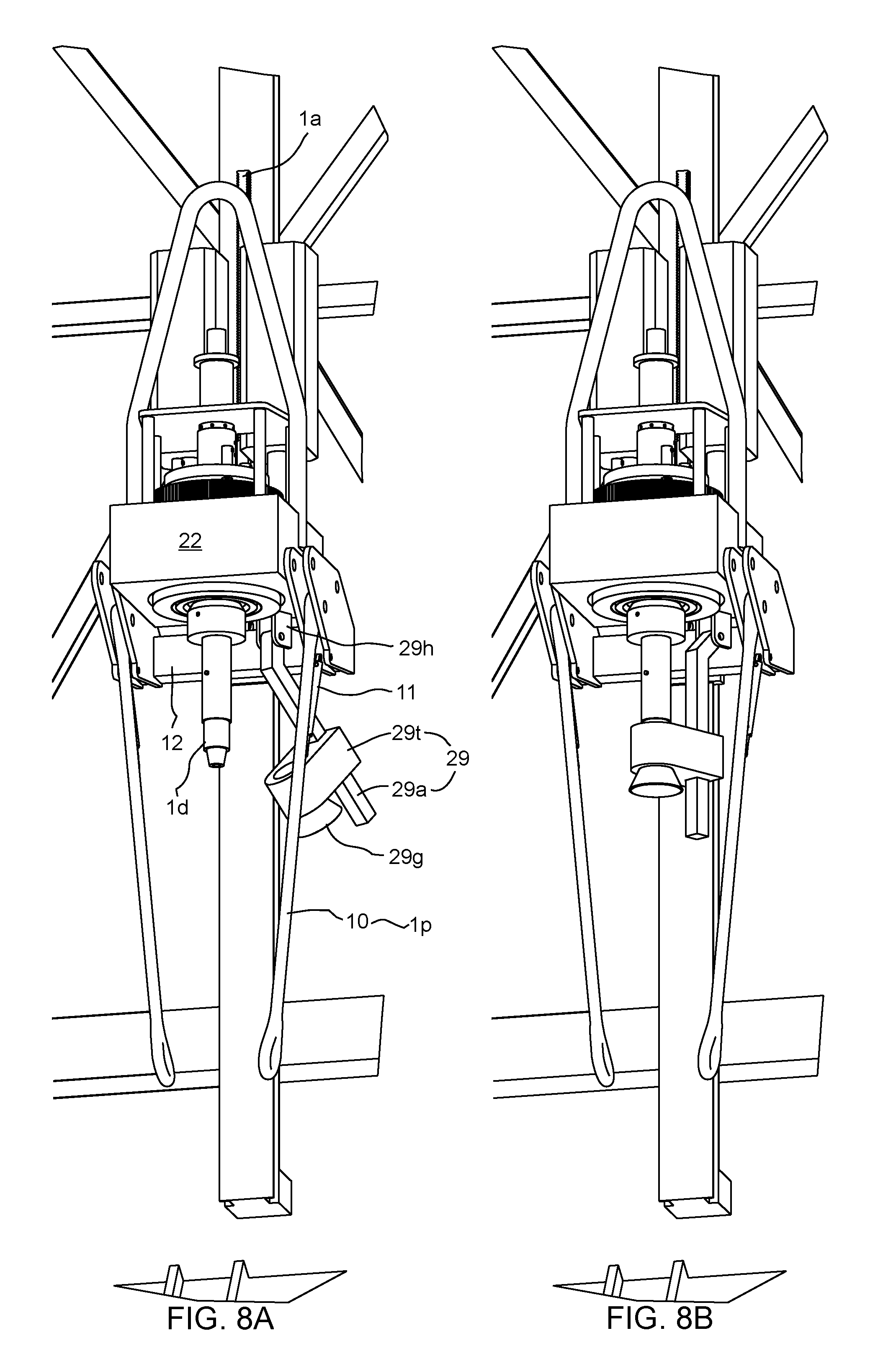
FIGS. 6, 7A, 7B, 8A, and 8B illustrate shifting of the top drive to the drilling mode.
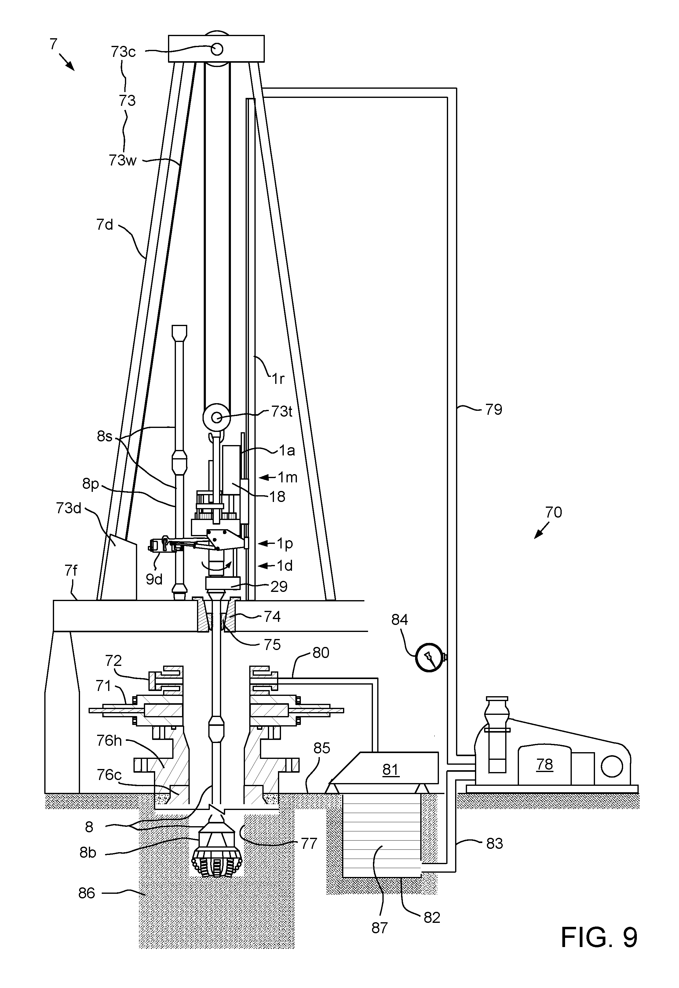
FIG. 9 illustrates the top drive system in the drilling mode.
FIG. 10 illustrates shifting of the top drive system from the drilling mode to the casing mode.
FIGS. 11 and 12A illustrate extension of a casing string using the top drive system in the casing mode. FIG. 12B illustrates running of the extended casing string into the wellbore using the top drive system.
FIGS. 13A and 13B illustrate a cementing unit of the top drive system.
FIG. 14 illustrates cementing of the casing string using the top drive system in a cementing mode.
FIG. 15 illustrates cementing of the casing string using an alternative cementing unit, according to another embodiment of the present disclosure.
DETAILED DESCRIPTION
FIG. 1 illustrates a top drive system 1, according to one embodiment of the present disclosure. The top drive system 1 may be a modular top drive system and may include a linear actuator 1a (FIG. 8A), several accessory tools (e.g., casing unit 1c, a drilling unit 1d, and a cementing unit 1s) a pipe handler 1p, a unit rack 1k, a motor unit 1m, a rail 1r, and a unit handler 1u. The unit handler 1u may include a post 2, a slide hinge 3, an arm 4, a holder 5, a base 6, and one or more actuators (not shown). One or more of the accessory tools may include a genset 51 (sometimes referred to as an engine-generator set, and typically including an electric generator and an engine or motor mounted together to form a single piece of equipment).
The top drive system 1 may be assembled as part of a drilling rig 7 by connecting a lower end of the rail 1r to a floor 7f or derrick 7d of the rig and an upper end of the rail to the derrick 7d such that a front of the rail is adjacent to a drill string opening in the rig floor. The rail 1r may have a length sufficient for the top drive system 1 to handle stands 8s of two to four joints of drill pipe 8p. The rail length may be greater than or equal to twenty-five meters and less than or equal to one hundred meters. The rail 1r may be a monorail (shown) or the top drive system may include twin rails instead of the monorail 1r.
The base 6 may mount the post 2 on or adjacent to a structure of the drilling rig 7, such as a subfloor structure, such as a catwalk (not shown) or pad. The unit rack 1k may also be located on or adjacent to the rig structure. The post 2 may extend vertically from the base 6 to a height above the rig floor 7f such that the unit handler 1p may retrieve any of the units 1c,d,s from the rack 1k and deliver the retrieved unit to the motor unit 1m.
The arm 4 may be connected to the slide hinge 3, such as by fastening. The slide hinge 3 may be transversely connected to the post 2, such as by a slide joint, while being free to move longitudinally along the post. The slide hinge 3 may also be pivotally connected to a linear actuator (not shown), such as by fastening. The slide hinge 3 may longitudinally support the arm 4 from the linear actuator while allowing pivoting of the arm relative to the post 2. The unit handler 1u may further include an electric or hydraulic slew motor (not shown) for pivoting the arm 4 about the slide hinge 3.
The linear actuator may have a lower end pivotally connected to the base 6 and an upper end pivotally connected to the slide hinge 3. The linear actuator may include a cylinder and a piston disposed in a bore of the cylinder. The piston may divide the cylinder bore into a raising chamber and a lowering chamber and the cylinder may have ports formed through a wall thereof and each port may be in fluid communication with a respective chamber. Each port may be in fluid communication with a manifold 60m of a hydraulic power unit (HPU) 60 (both in FIG. 5) via a control line (not shown). Supply of hydraulic fluid to the raising port may move the slide hinge 3 and arm 4 upward to the rig floor 7f. Supply of hydraulic fluid to the lowering port may move the slide hinge 3 and arm 4 downward toward the base 6.
Alternatively, the linear actuator may include an electro-mechanical linear actuator, such as a motor and lead screw or pinion and gear rod, instead of the piston and cylinder assembly.
The arm 4 may include a forearm segment, an aft-arm segment, and an actuated joint, such as an elbow, connecting the arm segments. The holder 5 may be releasably connected to the forearm segment, such as by fastening. The arm 4 may further include an actuator (not shown) for selectively curling and extending the forearm segment and relative to the aft-arm segment. The arm actuator may have an end pivotally connected to the forearm segment and another end pivotally connected to the aft-arm segment. The arm actuator may include a cylinder and a piston disposed in a bore of the cylinder. The piston may divide the cylinder bore into an extension chamber and a curling chamber and the cylinder may have ports formed through a wall thereof and each port may be in fluid communication with a respective chamber. Each port may be in fluid communication with the HPU manifold 60m via a control line (not shown). Supply of hydraulic fluid to the respective ports may articulate the forearm segment and holder 5 relative to the aft-arm segment toward the respective positions.
Alternatively, the arm actuator may include an electro-mechanical linear actuator, such as a motor and lead screw or pinion and gear rod, instead of the piston and cylinder assembly. Alternatively, the actuated joint may be a telescopic joint instead of an elbow. Additionally, the holder 5 may include a safety latch for retaining any of the units 1c,d,s thereto after engagement of the holder therewith to prevent unintentional release of the units during handling thereof. Additionally, the holder 5 may include a brake for torsionally connecting any of the units 1c,d,s thereto after engagement of the holder therewith to facilitate connection to the motor unit 1m.
Referring to FIG. 8A, the pipe handler 1p may include a drill pipe elevator 9 (FIG. 9), a pair of bails 10, a link tilt 11, and a slide hinge 12. The slide hinge 12 may be transversely connected to the front of the rail 1r such as by a slide joint, while being free to move longitudinally along the rail. Each bail 10 may have an eyelet formed at each longitudinal end thereof. An upper eyelet of each bail 10 may be received by a respective pair of knuckles of the slide hinge 12 and pivotally connected thereto, such as by fastening. Each bail 10 may be received by a respective ear of the drill pipe elevator 9d and pivotally connected thereto, such as by fastening.
The link tilt 11 may include a pair of piston and cylinder assemblies for swinging the elevator 9 relative to the slide hinge 12. Each piston and cylinder assembly may have a coupling, such as a hinge knuckle, formed at each longitudinal end thereof. An upper hinge knuckle of each piston and cylinder assembly may be received by the respective lifting lug of the slide hinge 12 and pivotally connected thereto, such as by fastening. A lower hinge knuckle of each piston and cylinder assembly may be received by a complementary hinge knuckle of the respective bail 10 and pivotally connected thereto, such as by fastening. A piston of each piston and cylinder assembly may be disposed in a bore of the respective cylinder. The piston may divide the cylinder bore into a raising chamber and a lowering chamber and the cylinder may have ports formed through a wall thereof and each port may be in fluid communication with a respective chamber. Each port may be in fluid communication with the HPU manifold 60m via a respective control line 66b,c (FIG. 5). Supply of hydraulic fluid to the raising port may lift the elevator 9 by increasing a tilt angle (measured from a longitudinal axis of the rail 1r). Supply of hydraulic fluid to the lowering port may drop the elevator 9 by decreasing the tilt angle.
The drill pipe elevator 9 may be manually opened and closed or the pipe handler 1p may include an actuator (not shown) for opening and closing the elevator. The drill pipe elevator 9 may include a bushing having a profile, such as a bottleneck, complementary to an upset formed in an outer surface of a joint of the drill pipe 8p adjacent to the threaded coupling thereof. The bushing may receive the drill pipe 8p for hoisting one or more joints thereof, such as the stand 8s. The bushing may allow rotation of the stand 8s relative to the pipe handler 1p. The pipe handler 1p may deliver the stand 8s to a drill string 8 where the stand 8s may be assembled therewith to extend the drill string during a drilling operation. When connected to the motor unit 1m, the pipe handler 1p may be capable of supporting the weight of the drill string 8 to expedite tripping of the drill string.
The linear actuator 1a may raise and lower the pipe handler 1p relative to the motor unit 1m and may include a gear rack, one or two pinions (not shown), and one or two pinion motors (not shown). The gear rack may be a bar having a geared upper portion and a plain lower portion. The gear rack may have a knuckle formed at a bottom thereof for pivotal connection with a lifting lug of the slide hinge 12, such as by fastening. Each pinion may be meshed with the geared upper portion and torsionally connected to a rotor of the respective pinion motor. A stator of each pinion motor may be connected to the motor unit 1m and be in electrical communication with a motor driver 61 via a cable 67b (both shown in FIG. 5). The pinion motors may share a cable via a splice (not shown). Each pinion motor may be reversible and rotation of the respective pinion in a first direction, such as counterclockwise, may raise the slide hinge 12 relative to the motor unit 1m and rotation of the respective pinion in a second opposite direction, such as clockwise, may lower the slide hinge relative to the motor unit. Each pinion motor may include a brake (not shown) for locking position of the slide hinge once the pinion motors are shut off. The brake may be disengaged by supply of electricity to the pinion motors and engaged by shut off of electricity to the pinion motors.
The linear actuator 1a may be capable of hoisting the stand 8s. A stroke of the linear actuator 1a may be sufficient to stab a top coupling of the stand 8s into a quill 37 of the motor unit 1m.
The unit rack 1k may include a base, a beam, two or more (three shown) columns connecting the base to the beam, such as by welding or fastening, and a parking spot for each of the units 1c,d,s (four spots shown). A length of the columns may correspond to a length of the longest one of the units 1c,d,s, such as being slightly greater than the longest length. The columns may be spaced apart to form parking spots (four shown) between adjacent columns. The units 1c,d,s may be hung from the beam by engagement of the parking spots with respective couplings 15 (FIG. 2B) of the units. Each parking spot may include an opening formed through the beam, a ring gear, and a motor. Each ring gear may be supported from and transversely connected to the beam by a bearing (not shown) such that the ring gear may rotate relative to the beam. Each bearing may be capable supporting the weight of any of the units 1c,d,s and placement of a particular unit in a particular parking spot may be arbitrary.
Each motor may include a stator connected to the beam and may be in electrical communication with the motor driver 61 via a cable (not shown). A rotor of each motor may be meshed with the respective ring gear for rotation thereof between a disengaged position and an engaged position. Each ring gear may have an internal latch profile, such as a bayonet profile, and each coupling 15 may include a head 15h having an external latch profile, such as a bayonet profile. The bayonet profiles may each have one or more (three shown) prongs and prong-ways spaced around the respective ring gears and heads 15h at regular intervals. When the prongs of the respective bayonet profiles are aligned, the external prongs of the heads 15h may be engaged with the internal prongs of the respective ring gears, thereby supporting the units 1c,d,s from the beam. When the external prongs of the heads 15h are aligned with the internal prong-ways of the ring gears (and vice versa), the heads may be free to pass through the respective ring gears.
Alternatively, the latch profiles may each be threads or load shoulders instead of bayonets. Alternatively, the unit rack 1k and the motor unit 1m may each have slips, a cone, and a linear actuator for driving the slips along the cone (or vice versa) instead of the latch profiles.
Each coupling 15 may further include a neck 15n extending from the head 15h and having a reduced diameter relative to a maximum outer diameter of the head for extending through the respective beam opening and respective ring gear. Each coupling 15 may further include a lifting shoulder 15s connected to a lower end of the neck 15n and having an enlarged diameter relative to the reduced diameter of the neck and a torso 15r extending from the lifting shoulder 15s and having a reduced diameter relative to the enlarged diameter of the lifting shoulder. The torso 15r may have a length corresponding to a length of the holder 5 for receipt thereof and a bottom of the lifting shoulder 15s may seat on a top of the holder for transport from the unit rack 1k to the motor unit 1m.
The unit rack 1k may further include a side bar for holding one or more accessories for connection to the forearm segment instead of the holder 5, such as a cargo hook 16 and a pipe clamp 17. The side bar may also hold the holder 5 when the unit handler 1u is equipped with one of the accessories.
FIG. 2A illustrates the motor unit 1m. The motor unit 1m may include one or more (pair shown) drive motors 18, a becket 19, a hose nipple 20, a mud swivel 21, a drive body 22, a drive ring, such as drive gear 23, a trolley 24 (FIG. 5), a thread compensator 25, a control, such as hydraulic, swivel 26, a down thrust bearing 27, an up thrust bearing 28, a backup wrench 29 (FIG. 8A), a swivel frame 30, a bearing retainer 31, a motor gear 32 (FIG. 5), and a latch 69 (FIG. 5). The drive body 22 may be rectangular, may have thrust chambers formed therein, may have an inner rib dividing the thrust chambers, and may have a central opening formed therethrough and in fluid communication with the chambers. The drive gear 23 may be cylindrical, may have a bore therethrough, may have an outer flange 23f formed in an upper end thereof, may have an outer thread formed at a lower end thereof, may have an inner locking profile 23k formed at an upper end thereof, and may have an inner latch profile, such as a bayonet profile 23b, formed adjacently below the locking profile. The inner bayonet profile 23b may be similar to the inner bayonet profile of the ring gears except for having a substantially greater thickness for sustaining weight of either the drill string 8 or a casing string 90 (FIG. 12A). The bearing retainer 31 may have an inner thread engaged with the outer thread of the drive gear 23, thereby connecting the two members.
The drive motors 18 may be electric (shown) or hydraulic (not shown) and have a rotor and a stator. A stator of each drive motor 18 may be connected to the trolley 24, such as by fastening, and be in electrical communication with the motor driver 61 via a cable 67c (FIG. 5). The motors 18 may be operable to rotate the rotor relative to the stator which may also torsionally drive respective motor gears 32. The motor gears 32 may be connected to the respective rotors and meshed with the drive gear 23 for torsional driving thereof.
Alternatively, the motor unit 1m may instead be a direct drive unit having the drive motor 18 centrally located.
Each thrust bearing 27, 28 may include a shaft washer, a housing washer, a cage, and a plurality of rollers extending through respective openings formed in the cage. The shaft washer of the down thrust bearing 27 may be connected to the drive gear 23 adjacent to a bottom of the flange thereof. The housing washer of the down thrust bearing 27 may be connected to the drive body 22 adjacent to a top of the rib thereof. The cage and rollers of the down thrust bearing 27 may be trapped between the washers thereof, thereby supporting rotation of the drive gear 23 relative to the drive body 22. The down thrust bearing 27 may be capable of sustaining weight of a tubular string, such as either the drill string 8 or the casing string 90, during rotation thereof. The shaft washer of the up thrust bearing 28 may be connected to the drive gear 23 adjacent to the bearing retainer 31. The housing washer of the up thrust bearing 28 may be connected to the drive body 22 adjacent to a bottom of the rib thereof. The cage and rollers of the up thrust bearing 28 may be trapped between the washers thereof.
The trolley 24 may be connected to a back of the drive body 22, such as by fastening. The trolley 24 may be transversely connected to a front of the rail 1r and may ride along the rail, thereby torsionally restraining the drive body 22 while allowing vertical movement of the motor unit 1m with a travelling block 73t (FIG. 9) of a rig hoist 73. The becket 19 may be connected to the drive body 22, such as by fastening, and the becket may receive a hook of the traveling block 73t to suspend the motor unit 1m from the derrick 7d.
Alternatively, motor unit 1m may include a block-becket instead of the becket 19 and the block-becket may obviate the need for a separate traveling block 73t.
The hose nipple 20 may be connected to the mud swivel 21 and receive an end of a mud hose (not shown). The mud hose may deliver drilling fluid 87 (FIG. 9) from a standpipe 79 (FIG. 9) to the hose nipple 20. The mud swivel 21 may have an outer non-rotating barrel 210 connected to the hose nipple 20 and an inner rotating barrel 21n. The mud swivel 21 may have a bearing (not shown) and a dynamic seal (not shown) for accommodating rotation of the rotating barrel relative to the non-rotating barrel. The outer non-rotating barrel 210 may be connected to a top of the swivel frame 30, such as by fastening. The swivel frame 30 may be connected to a top of the drive body 22, such as by fastening. The inner rotating barrel 21n may have an upper portion disposed in the outer non-rotating barrel 210 and a stinger portion extending therefrom, through the control swivel 26, and through the compensator 25. A lower end of the stinger portion may carry a stab seal for engagement with an inner seal receptacle 15b of each coupling 15 when the respective unit 1c,d,s is connected to the motor unit 1m, thereby sealing an interface formed between the units.
The control swivel 26 may include a non-rotating inner barrel and a rotating outer barrel. The inner barrel may be connected to the swivel frame 30 and the outer barrel may be supported from the inner barrel by one or more bearings. The outer barrel may have hydraulic ports (six shown) formed through a wall thereof, each port in fluid communication with a respective hydraulic passage formed through the inner barrel (only two passages shown). An interface between each port and passage may be straddled by dynamic seals for isolation thereof. The inner barrel passages may be in fluid communication with the HPU manifold 60m via a plurality of fluid connectors, such as the hydraulic conduits 64a-e (FIG. 5), and the outer barrel ports may be in fluid communication with either the linear actuator 33 or lock ring 34 via jumpers (not shown). The outer barrel ports may be disposed along the outer barrel. The inner barrel may have a mandrel portion extending along the outer barrel and a head portion extending above the outer barrel. The head portion may connect to the swivel frame 30 and have the hydraulic ports extending therearound.
The compensator 25 may include a linear actuator 33, the lock ring 34, and one or more (such as three, but only one shown) lock pins 35. The lock ring 34 may have an outer flange 34f formed at an upper end thereof, a bore formed therethrough, one or more chambers housing the lock pins 35 formed in an inner surface thereof, a locking profile 34k formed in a lower end thereof, members, such as males 34m, of a hydraulic junction 36 (FIG. 7A) formed in the lower end thereof, and hydraulic passages (two shown) formed through a wall thereof. The locking profile 34k may include a lug for each prong-way of the external bayonet profiles of the heads 15h.
Each lock pin 35 may be a piston dividing the respective chamber into an extension portion and a retraction portion and the lock ring 34 may have passages formed through the wall thereof for the chamber portions. Each passage may be in fluid communication with the HPU manifold 60m via a respective fluid connector, such as hydraulic conduit 64a (FIG. 3, only one shown). The lock pins 35 may share an extension control line and a retraction control line via a splitter (not shown). Supply of hydraulic fluid to the extension passages may move the lock pins 35 to an engaged position where the pins extend into respective slots 15t formed in the prong-ways of the heads 15h, thereby longitudinally connecting the lock ring 34 to a respective unit 1c,d,s. Supply of hydraulic fluid to the retraction passages may move the lock pins 35 to a release position (shown) where the pins are contained in the respective chambers of the lock ring 34.
The linear actuator 33 may include one or more, such as three, piston and cylinder assemblies 33a,b for vertically moving the lock ring 34 relative to the drive gear 23 between a lower hoisting position (FIG. 7A) and an upper ready position (shown). A bottom of the lock ring flange 34f may be seated against a top of the drive gear flange 23f in the hoisting position such that string weight carried by either the drilling unit 1d or the casing unit 1c may be transferred to the drive gear 23 via the flanges and not the linear actuator 33 which may be only capable of supporting stand weight or weight of a casing joint 90j (FIG. 12A) of casing. String weight may be one hundred (or more) times that of stand weight or joint weight. A piston of each assembly 33a,b may be seated against the respective cylinder in the ready position.
Each cylinder of the linear actuator 33 may be disposed in a respective peripheral socket formed through the lock ring flange 34f and be connected to the lock ring 34, such as by threaded couplings. Each piston of the linear actuator 33 may extend into a respective indentation formed in a top of the drive gear flange 23f and be connected to the drive gear 23, such as by threaded couplings. Each socket of the lock ring flange 34f may be aligned with the respective lug of the locking profile 34k and each indentation of the drive gear flange 23f may be aligned with a receptacle of the locking profile 23k such that connection of the linear actuator 33 to the lock ring 34 and drive gear 23 ensures alignment of the locking profiles.
Each piston of the linear actuator 33 may be disposed in a bore of the respective cylinder. The piston may divide the cylinder bore into a raising chamber and a lowering chamber and the cylinder may have ports (only one shown) formed through a wall thereof and each port may be in fluid communication with a respective chamber. Each port may be in fluid communication with the HPU manifold 60m via a respective fluid connector, such as hydraulic conduit 64b (only one shown in FIG. 5). Supply of hydraulic fluid to the raising port may lift the lock ring 34 toward the ready position. Supply of hydraulic fluid to the lowering port may drop the lock ring 34 toward the hoisting position. A stroke length of the linear compensator 25 between the ready and hoisting positions may correspond to, such as being equal to or slightly greater than, a makeup length of the drill pipe 8p and/or casing joint 90j.
Each coupling 15 may further include mating members, such as females 15f, of the junction 36 formed in a top of the prongs of the head 15h. The male members 34m may each have a nipple for receiving a respective jumper from the control swivel 26, a stinger, and a passage connecting the nipple and the stinger. Each stinger may carry a respective seal. The female member 15f may have a seal receptacle for receiving the respective stinger. The junction members 34m, 15f may be asymmetrically arranged to ensure that the male member 34m is stabbed into the correct female member 15f.
Referring to FIG. 8A, the backup wrench 29 may include a hinge 29h, a tong 29t, a guide 29g, an arm 29a, a tong actuator (not shown), a tilt actuator (not shown), and a linear actuator (not shown). The tong 29t may be transversely connected to the arm 29a while being longitudinally movable relative thereto subject to engagement with a stop shoulder thereof. The hinge 29h may pivotally connect the arm 29a to a bottom of the drive body 22. The hinge 29h may include a pair of knuckles fastened or welded to the drive body 22 and a pin extending through the knuckles and a hole formed through a top of the arm 29a. The tilt actuator may include a piston and cylinder assembly having an upper end pivotally connected to the bottom of the drive body 22 and a lower end pivotally connected to a back of the arm 29a. The piston may divide the cylinder bore into an activation chamber and a stowing chamber and the cylinder may have ports (only one shown) formed through a wall thereof and each port may be in fluid communication with a respective chamber. Each port may be in fluid communication with the HPU manifold 60m via a respective control line (not shown). Supply of hydraulic fluid to the activation port may pivot the tong 29t about the hinge 29h toward the quill 37. Supply of hydraulic fluid to the stowing port may pivot the tong 29t about the hinge 29h away from the quill 37.
The tong 29t may include a housing having an opening formed therethrough and a pair of jaws (not shown) and the tong actuator may move one of the jaws radially toward or away from the other jaw. The guide 29g may be a cone connected to a lower end of the tong housing, such as by fastening, for receiving a threaded coupling, such as a box, of the drill pipe 8p. The quill 37 may extend into the tong opening for stabbing into the drill pipe box. Once stabbed, the tong actuator may be operated to engage the movable jaw with the drill pipe box, thereby torsionally connecting the drill pipe box to the drive body 22. The tong actuator may be hydraulic and operated by the HPU 60 via a control line 66d (FIG. 5).
The backup wrench linear actuator may include a gear rack (not shown) formed along a straight lower portion of the arm 29a, one or two pinions (not shown), and one or two pinion motors (not shown). The arm 29a may have a deviated upper portion engaged with the hinge 29h. Each pinion may be meshed with the gear rack of the arm 29a and torsionally connected to a rotor of the respective pinion motor. A stator of each pinion motor may be connected to the housing of the tong 29t and be in electrical communication with the motor driver 61 via a cable 67a (FIG. 5). The pinion motors may share a cable via a splice (not shown). Each pinion motor may be reversible and rotation of the respective pinion in a first direction, such as counterclockwise, may raise the tong 29t along the arm 29a and rotation of the respective pinion in a second opposite direction, such as clockwise, may lower the tong along the arm. Each pinion motor may include a brake (not shown) for locking position of the tong 29t once the pinion motors are shut off. The brake may be disengaged by supply of electricity to the pinion motors and engaged by shut off of electricity to the pinion motors.
Referring to FIG. 5, the latch 69 may include a one or more (pair shown) units disposed at sides of the drive body 22. Each latch unit may include a lug connected, such as by fastening or welding, to the drive body 22 and extending from a bottom thereof, a fastener, such as a pin, and an actuator. Each lug may have a hole formed therethrough and aligned with a respective actuator. Each interior knuckle of the slide hinge 12 may have a hole formed therethrough for receiving the respective latch pin. Each actuator may include a cylinder and piston (not shown) connected to the latch pin and disposed in a bore of the cylinder. Each cylinder may be connected to the drive body 22, such as by fastening, adjacent to the respective lug. The piston may divide the cylinder bore into an extension chamber and a retraction chamber and the cylinder may have ports formed through a wall thereof and each port may be in fluid communication with a respective chamber. Each port may be in fluid communication with the HPU manifold 60m via a control line 66a (FIG. 3, only one shown). The latch units may share an extension control line and a retraction control line via a splitter (not shown). Supply of hydraulic fluid to the extension port may move the pin to an engaged position (shown) where the pin extends through the respective lug hole and the respective interior knuckle hole of the slide hinge 12, thereby connecting the pipe handler 1p to the drive body 22. Supply of hydraulic fluid to the retraction port may move the pin to a release position (not shown) where the pin is clear of the interior slide hinge knuckle.
FIG. 2B illustrates the drilling unit 1d. The drilling unit 1d may include the coupling, the quill 37, an internal blowout preventer (IBOP) 38, and one or more, such as two (only one shown), hydraulic passages 39. The quill 37 may be a shaft, may have an upper end connected to the torso 15r, may have a bore formed therethrough, may have a threaded coupling, such as a pin, formed at a lower end thereof. In some embodiments, the IBOP could be controlled from a separate control unit at the accessory tool. The separate control unit could be powered from the genset 51. For example, the genset 51 could be connected to the tool so as to avoid impacts during the drilling process, such as with springs.
The IBOP 38 may include an internal sleeve 38v and one or more shutoff valves 38u,b. The IBOP may further include an automated actuator for one 38u of the shutoff valves 38u,b and the other 38b of the shutoff valves 38u,b may be manually actuated. Each shutoff valve 38u,b may be connected to the sleeve 38v and the sleeve may be received in a recessed portion of the quill 37 and/or coupling 15. The IBOP valve actuator may be disposed in a socket formed through a wall of the quill 37 and/or coupling 15 and may include an opening port and/or a closing port and each port may be in fluid communication with the HPU manifold 60m via a respective hydraulic passage 39, respective male 34m and female 15f members, respective jumpers, the control swivel 26, and respective fluid connectors, such as hydraulic conduits 64c,d (FIG. 5). The hydraulic conduit 64e may connect to a drain port of the IBOP valve actuator.
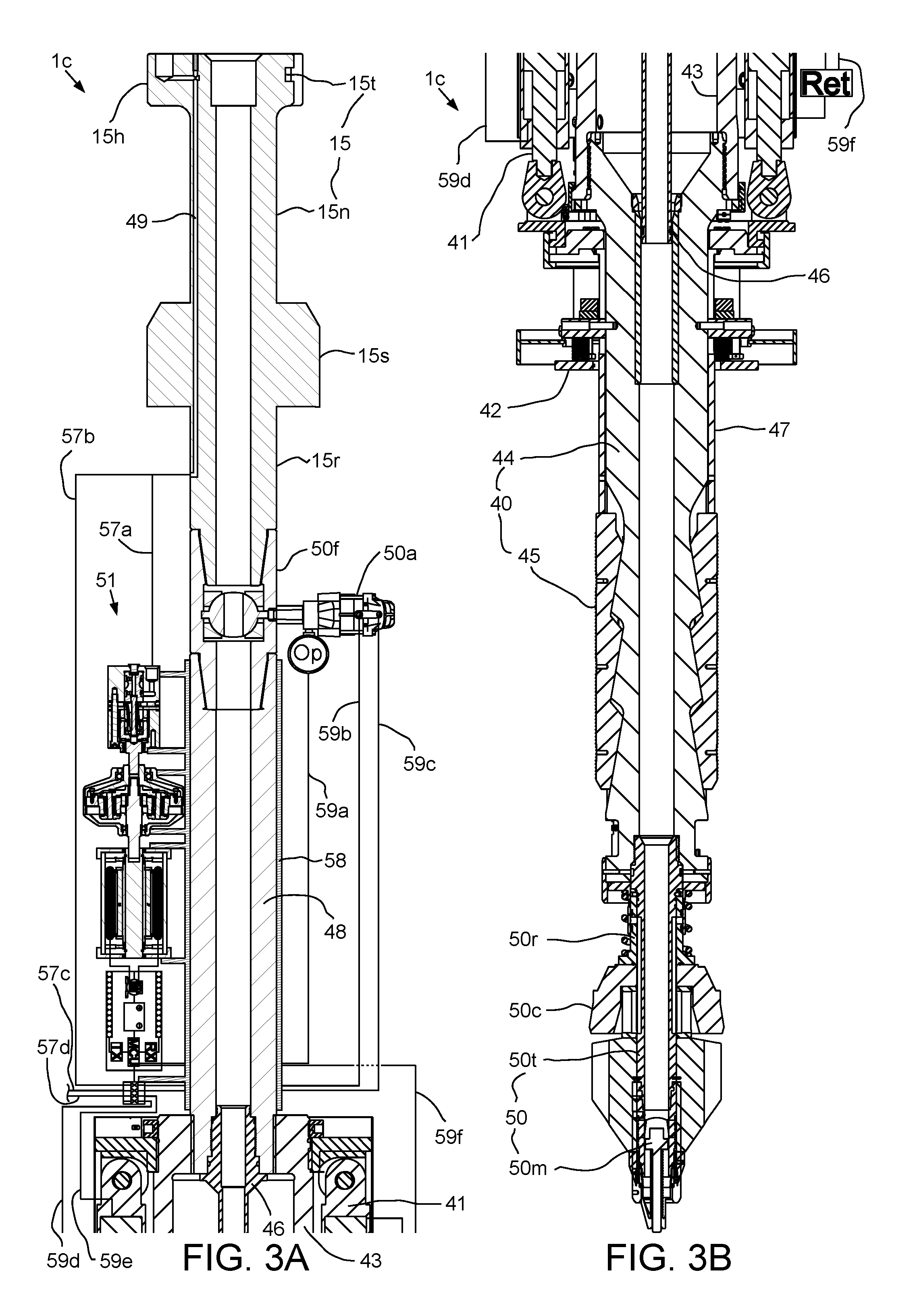
FIGS. 3A and 3B illustrate the casing unit 1c. The casing unit 1c may include the coupling 15, a clamp, such as a spear 40, an adapter 48, one or more, such as three (only one shown), hydraulic passages 49, a fill up tool 50, a genset 51, and a frame 58. The fill up tool 50 may include a flow tube 50t, a stab seal, such as a cup seal 50c, a release valve 50r, a mud saver valve 50m, a fill up valve 50f, and a fill up valve actuator 50a.
The fill up valve 50f may include a valve member, such as a ball, a valve seat, and a housing. The housing may be tubular, may have an upper end connected to the torso 15r and a lower end connected to the adapter 48. The valve seat may be disposed in the housing, may be made from a metal/alloy, ceramic/cermet, or polymer and may be connected to the housing, such as by fastening. The ball may be disposed in a spherical recess formed by the valve seat and rotatable relative to the housing between an open position (shown) and a closed position. The ball may have a bore therethrough corresponding to the housing bore and aligned therewith in the open position. A wall of the ball may close the housing bore in the closed position. The ball may have a stem extending into an actuation port formed through a wall of the housing. The stem may mate with a shaft of the actuator 50a and the actuator may be operable to rotate the ball between the open and the closed positions.
The fill up valve actuator 50a may be hydraulic and may have a position sensor Op in communication with the shaft and in communication with a microcontroller MCU of the genset 51 via a data cable 59a. The position sensor Op may also be electrically powered by the microcontroller MCU via the data cable 59a. The position sensor Op may verify that the actuator 50a has properly functioned to open and/or close the fill up valve 50f. The actuator 50a may be operated by one or more fluid connectors, such as hydraulic conduits 59b,c leading to a fluid, such as hydraulic, manifold 56 (FIG. 4) of the genset 51.
The adapter 48 may be tubular, may have a bore formed therethrough, and may have an upper end connected to the housing of the fill up valve 50f, and may have an outer thread and an inner receptacle formed at a lower end thereof. The frame 58 may mount the genset 51 to an outer surface of the adapter 48.
The spear 40 may include a clamp actuator, such as linear actuator 41, a bumper 42, a collar 43, a mandrel 44, a set of grippers, such as slips 45, a seal joint 46, and a sleeve 47. The collar 43 may have an inner thread formed at each longitudinal end thereof. The collar upper thread may be engaged with the outer thread of the adapter 48, thereby connecting the two members. The collar lower thread may be engaged with an outer thread formed at an upper end of the mandrel 44 and the mandrel may have an outer flange formed adjacent to the upper thread and engaged with a bottom of the collar 43, thereby connecting the two members.
The seal joint 46 may include the inner barrel, an outer barrel, and a nut. The inner barrel may have an outer thread engaged with a threaded portion of the adapter receptacle and an outer portion carrying a seal engaged with a seal bore portion of the adapter receptacle. The mandrel 44 may have a bore formed therethrough and an inner receptacle formed at an upper portion thereof and in fluid communication with the bore. The mandrel receptacle may have an upper conical portion, a threaded mid portion, and a recessed lower portion. The outer barrel may be disposed in the recessed portion of the mandrel 44 and trapped therein by engagement of an outer thread of the nut with the threaded mid portion of the mandrel receptacle. The outer barrel may have a seal bore formed therethrough and a lower portion of the inner barrel may be disposed therein and carry a stab seal engaged therewith.
The linear actuator 41 may include a housing, an upper flange, a plurality of piston and cylinder assemblies, a lower flange, and a position sensor Ret in communication with one or more of the piston and cylinder assemblies. The position sensor Ret may be also be in communication with the microcontroller MCU via a data cable 59f. The position sensor Ret may also be electrically powered by the microcontroller MCU via the data cable 59f. The position sensor Ret may verify that the piston and cylinder assemblies have properly functioned to extend and/or retract the slips 45. The housing may be cylindrical, may enclose the cylinders of the assemblies, and may be connected to the upper flange, such as by fastening. The collar 43 may also have an outer thread formed at the upper end thereof. The upper flange may have an inner thread engaged with the outer collar thread, thereby connecting the two members. Each flange may have a pair of lugs for each piston and cylinder assembly connected, such as by fastening or welding, thereto and extending from opposed surfaces thereof.
Each cylinder of the linear actuator 41 may have a coupling, such as a hinge knuckle, formed at an upper end thereof. The upper hinge knuckle of each cylinder may be received by a respective pair of lugs of the upper flange and pivotally connected thereto, such as by fastening. Each piston of the linear actuator 41 may have a coupling, such as a hinge knuckle, formed at a lower end thereof. Each piston of the linear actuator 41 may be disposed in a bore of the respective cylinder. The piston may divide the cylinder bore into a raising chamber and a lowering chamber and the cylinder may have ports formed through a wall thereof and each port may be in fluid communication with a respective chamber.
Each port may be in fluid communication with the hydraulic manifold 56 via respective fluid connectors, such as hydraulic conduits 59d,e. Supply of hydraulic fluid to the raising port may lift the lower flange to a retracted position (shown). Supply of hydraulic fluid to the lowering port may drop the lower flange toward an extended position (not shown). The piston and cylinder assemblies may share an extension conduit 59e and a retraction conduit 59d via a splitter (not shown).
The sleeve 47 may have an outer shoulder formed in an upper end thereof trapped between upper and lower retainers. A washer may have an inner shoulder formed in a lower end thereof engaged with a bottom of the lower retainer. The washer may be connected to the lower flange, such as by fastening, thereby longitudinally connecting the sleeve 47 to the linear actuator 41. The sleeve 47 may also have one or more (pair shown) slots formed through a wall thereof at an upper portion thereof.
The bumper 42 include a striker and a base connected to the mandrel, such as by one or more threaded fasteners, each fastener extending through a hole thereof, through a respective slot of the sleeve 47, and into a respective threaded socket formed in an outer surface of the mandrel 44, thereby also torsionally connecting the sleeve to the mandrel while allowing limited longitudinal movement of the sleeve relative to the mandrel to accommodate operation of the slips 45. The striker may be linked to the base by one or more (pair shown) compression springs. A lower portion of the spear 40 may be stabbed into the casing joint 90j until the striker engages a top of the casing joint. The springs may cushion impact with the top of the casing joint 90j to avoid damage thereto.
The sleeve 47 may extend along the outer surface of the mandrel from the lower flange of the linear actuator 41 to the slips 45. A lower end of the sleeve 47 may be connected to upper portions of each of the slips 45, such as by a flanged (i.e., T-flange and T-slot) connection. Each slip 46 may be radially movable between an extended position and a retracted position by longitudinal movement of the sleeve 47 relative to the slips. A slip receptacle may be formed in an outer surface of the mandrel 44 for receiving the slips 45. The slip receptacle may include a pocket for each slip 46, each pocket receiving a lower portion of the respective slip. The mandrel 44 may be connected to lower portions of the slips 45 by reception thereof in the pockets. Each slip pocket may have one or more (three shown) inclined surfaces formed in the outer surface of the mandrel 44 for extension of the respective slip. A lower portion of each slip 46 may have one or more (three shown) inclined inner surfaces corresponding to the inclined slip pocket surfaces.
Downward movement of the sleeve 47 toward the slips 45 may push the slips along the inclined surfaces, thereby wedging the slips toward the extended position. The lower portion of each slip 46 may also have a guide profile, such as tabs, extending from sides thereof. Each slip pocket may also have a mating guide profile, such as grooves, for retracting the slips 45 when the sleeve 47 moves upward away from the slips. Each slip 46 may have teeth formed along an outer surface thereof. The teeth may be made from a hard material, such as tool steel, ceramic, or cermet for engaging and penetrating an inner surface of the casing joint 90j, thereby anchoring the spear 40 to the casing joint.
The cup seal 50c may have an outer diameter slightly greater than an inner diameter of the casing joint 90j to engage the inner surface thereof during stabbing of the spear 40 therein. The cup seal 50c may be directional and oriented such that pressure in the casing bore energizes the seal into engagement with the casing joint inner surface. An upper end of the flow tube 50t may be connected to a lower end of the mandrel 44, such as by threaded couplings. The mud saver valve 50m may be connected to a lower end of the flow tube 50t, such as by threaded couplings. The cup seal 50c and release valve 50r may be disposed along the flow tube 50t and trapped between a bottom of the mandrel 44 and a top of the mudsaver valve 50m.
The spear 40 may be capable of supporting weight of the casing string 90. The string weight may be transferred to the becket 19 via the slips 45, the mandrel 44, the collar 43, the adapter 48, the coupling 15, the bayonet profile 23b, the down thrust bearing 27, the drive body 22. Fluid may be injected into the casing string 90 via the hose nipple 20, the mud swivel 21, the coupling 15, the adapter 48, the seal joint 46, the mandrel 44, the flow tube 50t, and the mud saver valve 50m.
Alternatively, the clamp may be a torque head instead of the spear 40. The torque head may be similar to the spear except for receiving an upper portion of the casing joint 90j therein and having the set of grippers for engaging an outer surface of the casing joint instead of the inner surface of the casing joint.
FIG. 4 illustrates the genset 51. The genset 51 may include a fluid driven, such as hydraulic, motor 52, a gearbox 53, an electric generator 54, a control unit 55, and the hydraulic manifold 56. The gearbox 53 may be a planetary gearbox.
Alternatively, the control swivel 26, the fluid driven motor 52, the fluid manifold 56, the linear actuator 41, and the fill up valve actuator 50a may be pneumatic instead of hydraulic.
The fluid driven motor 52 may be a gerotor motor and include a housing 52h, a drive shaft 52d, a valve shaft 52v, an output shaft 52o, an orbital gear set having a rotor 52r and a stator 52s, a plurality of roller vanes 52n, and a valve spool 52p. To facilitate assembly, the housing 52h may include two or more sections connected together, such as by one or more threaded fasteners. The output shaft 52o may have a hollow upper head disposed in the housing and a lower shank extending therethrough. The head may have a torsional profile, such as splines, formed in an inner surface thereof. A shaft spacer and a lower portion of the drive shaft 52d may each have teeth meshed with the splines, thereby torsionally connecting the members. The shaft spacer may also have a torsional profile formed in an inner surface thereof meshed with a torsional profile formed in a lower end of the valve shaft 52v.
The drive shaft 52d may be disposed in the head with a sufficient clearance formed therebetween to accommodate articulation of the drive shaft with the orbiting of the rotor 52r. The stator 52s may be disposed between the housing sections and connected thereto by the threaded fasteners. The roller vanes 52n may be disposed in sockets formed in the stator 52s and may be trapped between the housing sections. The rotor 52r may be disposed in the stator 52s and have a number of lobes formed in an outer surface thereof equal to the number of roller vanes minus one. Selective supply of pressurized hydraulic fluid by the valve spool 52p through pressure chambers formed between the rotor 52r and the stator 52s may drive the rotor in an orbital movement within the stator, thereby converting fluid energy from the hydraulic fluid into kinetic energy of the output shaft 52o.
The rotor 52r may have a torsional profile formed in an inner surface thereof meshed with a torsional profile formed of the upper portion of the drive shaft 52d, thereby torsionally connecting the two members. The valve shaft 52v may extend through the drive shaft 52s and have an upper portion with a torsional profile meshed with a torsional profile formed in a lower portion of the valve spool 52p. An inlet may be formed through a wall of the housing 52h to provide fluid communication between the valve spool 52p and a fluid connector, such as hydraulic conduit 57a leading to the hydraulic passage 49. An outlet (not shown) may be formed through a wall of the housing 52h to provide fluid communication between the valve spool 52p and a fluid connector (not shown) leading to a second hydraulic passage of the coupling 15.
The valve spool 52p may be disposed in the housing 52h and may rotate with the output shaft 52o via the valve shaft 52v. The valve spool 52p may have flow slots formed in an outer surface thereof that selectively provide fluid communication between the inlet and outlet and the appropriate pressure chambers formed between the rotor 52r and the stator 52s. A bushing may be disposed between the housing 52h and the output shaft 52o for radial support of the output shaft therefrom. A thrust bearing may be disposed between the housing 52h and the output shaft 52o for longitudinal support of the output shaft therefrom. One or more (pair shown) dynamic seals may be disposed between the housing 52h and the output shaft 52o to isolate the rotating interface therebetween for prevention of loss of hydraulic fluid from the fluid driven motor 52 and for prevention of contaminants from entering therein.
The gear box 53 may be planetary and include a housing 53h and a cover 53c connected thereto, such as by fasteners (not shown). The housing 53h and cover 53c may enclose a lubricant chamber sealed at ends thereof by oil seals. The gear box 53 may further include an input disk 53k having a hub extending from an upper end of the lubricant chamber and torsionally connected to the output shaft 52o of the fluid driven motor 52 by mating profiles (not shown), such as splines, formed at adjacent ends thereof. The gear box 53 may further include an output shaft 53p extending from a lower end of the lubricant chamber and torsionally connected to a shaft 54s of the electric generator 54 by mating profiles (not shown), such as splines, formed at adjacent ends thereof.
Each of the output shaft 53p and input disk 53k may be radially supported from the respective cover 53c and housing 53h for rotation relative thereto by respective bearings. The hub of the input disk 53k may receive an end of the output shaft 53p and a needle bearing may be disposed therebetween for supporting the output shaft therefrom while allowing relative rotation therebetween. A sun gear 53s may be disposed in the lubricant chamber and may be mounted onto the output shaft 53p. A stationary housing gear 53g may be disposed in the lubricant chamber and mounted to the housing 53h. A plurality of planetary rollers 53r may also be disposed in the lubricant chamber.
Each planetary roller 53r may include a planetary gear 53e disposed between and meshed with the sun gear 53s and the housing gear 53g. The planetary gears 53e may be linked by a carrier 53b which may be radially supported from the output shaft 53p by a bearing to allow relative rotation therebetween. Each planetary roller 53r may further include a support shaft 53f which is supported at its free end by a support ring and on which the respective planetary gear 53e may be supported by a bearing. Each planetary gear 53e may include first and second sections of different diameters, the first section meshing with the housing gear 53g and the sun gear 53s and the second section meshing with an input gear 53j and a support gear 53b. The input gear 53j may be mounted to the input disk 53k by fasteners. The support gear 53b may be radially supported from the input shaft 53p by a bearing to allow relative rotation therebetween.
The support shafts 53f may be arranged at a slight angle with respect to longitudinal axes of the output shaft 53p and input disk 53k. The planetary gears 53e, housing gear 53g, input gear 53j, and support gear 53b may also be slightly conical so that, upon assembly of the gear box 53, predetermined traction surface contact forces may be generated. The gear box 53 may further include assorted thrust bearings disposed between various members thereof.
In operation, rotation of the input disk 53k by the fluid driven motor 52 may drive the input gear 53j. The input gear 53j may drive the planetary gears 53e to roll along the housing gear 53g while also driving the sun gear 53s. Since the diameter of the second section of each planetary gear 53e may be significantly greater than that of the first section, the circumferential speed of the second section may correspondingly be significantly greater than that of the first section, thereby providing for a speed differential which causes the output shaft 53p to counter-rotate at a faster speed corresponding to the difference in diameter between the planetary gear sections. Driving torque of the output shaft 53p is also reduced accordingly.
Alternatively, the diameter of the first section of each planetary gear 53e may be greater in diameter than that of the second section resulting in rotation of the input gear 53j in the same direction as the input shaft 53p again at a speed corresponding to the difference in diameter between the two sections.
The electric generator 54 may include a rotor, a stator, and a pair of bearings supporting the rotor for rotation relative to the stator. The electric generator 54 may be a permanent magnet generator. For example, the rotor may include a hub 54b made from a magnetically permeable material, a plurality of permanent magnets 54m torsionally connected to the hub, and a shaft 54s. The rotor may include one or more pairs of permanent magnets 54m having opposite polarities N,S. The permanent magnets 54m may also be fastened to the hub 54b, such as by retainers. The hub 54b may be torsionally connected to the shaft 54s and fastened thereto. The stator may include a housing 54h, a core 54c, a pair of end caps 54p, and a plurality of windings 54w, such as three (only two shown). The core 54c may include a stack of laminations made from a magnetically permeable material. The stack may have lobes formed therein, each lobe for receiving a respective winding. The core 54c may be longitudinally and torsionally connected to the housing 54h, such as by an interference fit.
The control unit 55 may include a power converter 55c, an electrical energy storage device, such as a battery 55b, the microcontroller MCU, a wireless data link. The wireless data link may include a transmitter TX, a receiver RX, an antenna 55a. The transmitter TX and receiver RX may be separate devices (as shown) or may be integrated into a single transceiver. The transmitter TX and receiver RX may share the single antenna 55a (shown) or each have their own antenna. The wireless data link may be half-duplex or full-duplex. The power converter 55c may have an input in electrical communication with each winding 54w of the electric generator 54 and an output in electrical communication with the battery 55b. The power converter 55c may receive a multi-phase, such as three phase, power signal from the electric generator 54 and convert the power signal into a direct current power signal for charging the battery 55b. The power converter 55c may also step-down a voltage of the power signal from the electric generator 54 to a voltage usable by the battery 55b, such as three, six, nine, twelve, or twenty-four volts. The battery 55b may also be in electrical communication with the microcontroller MCU. The transmitter TX may be in electrical communication with the microcontroller MCU and the antenna 55a and may include an amplifier, a modulator, and an oscillator. The receiver RX may be in electrical communication with the microcontroller MCU and the antenna 55a and may include an amplifier, a demodulator, and a filter. The microcontroller MCU may receive instruction signals, via the antenna 55a and receiver RX, from a control console 62 (FIG. 5) to operate the fill up valve actuator 50a and/or the linear actuator 41 in response thereto. The instruction signals may be radio frequency wireless signals and may also be digital. The instruction signals may be received or transmitted with the used of the wireless data link. The microcontroller MCU may receive position statuses from the position sensors Op, Ret, and may send the position statuses to the control console 62 via the antenna 55a and transmitter TX.
Alternatively, the electrical energy storage device may be a super-capacitor, capacitor, or inductor instead of a battery.
The hydraulic manifold 56 may include a plurality of control valves, such as directional control valves, for operating the fill up valve actuator 50a and the linear actuator 41. Each control valve may be operated by an electric actuator (not shown) in electrical communication with the microcontroller MCU. An inlet of the hydraulic manifold 56 may be in fluid communication with the hydraulic passage 49 via a fluid connector, such as hydraulic conduit 57b. The inlet of the hydraulic manifold 56 may also be in fluid communication with the second hydraulic passage of the coupling 15 via another fluid connector, such as hydraulic conduit 57c. The inlet of the hydraulic manifold 56 may also be in fluid communication with a third hydraulic passage of the coupling 15 via another fluid connector, such as hydraulic conduit 57d. The hydraulic conduits 57a,b may both be in simultaneous fluid communication with the hydraulic passage 49 via a splitter.
When the casing unit 1c is connected to the motor unit 1m, the hydraulic conduit 64c may be connected to the hydraulic conduits 57a,b via the control swivel 26 and the hydraulic passage 49. The hydraulic conduit 64d may be connected to the hydraulic conduit 57c and the outlet of the fluid driven motor 52 via the control swivel 26 and the second hydraulic passage of the coupling 15. The hydraulic conduit 64e may be connected to the hydraulic conduit 57d via the control swivel 26 and the second hydraulic passage of the coupling 15. The hydraulic conduit 64c may be a supply line. The hydraulic conduit 64d may be a return line. The hydraulic conduit 64e may be a drain line. The microcontroller MCU may operate the hydraulic manifold 56 to selectively provide fluid communication between the hydraulic conduits 57b-d and the hydraulic conduits 59b-e based on the instruction signals from the control console 62.
Also as the casing unit 1c is connected to the motor unit 1m, the genset 51 may receive hydraulic fluid from the HPU 60 via the hydraulic conduit 57a, hydraulic passage 49, and hydraulic conduit 64c and return spent hydraulic fluid to the HPU via the hydraulic conduit leading from the second hydraulic passage of the coupling 15, the second hydraulic passage of the coupling, and the hydraulic conduit 64d, thereby driving the fluid driven motor 52. The fluid driven motor 52 may in turn drive the electric generator 54 via the gearbox 53. The electric generator 54 may power the control unit 55 which may await instruction signals from the control console 62 to operate the spear 40 and/or the fill up valve 50f via the hydraulic manifold 56.
FIG. 5 is a control diagram of the top drive system 1 in the drilling mode. The HPU 60 may include a pump 60p, a check valve 60k, an accumulator 60a, a reservoir 60r of hydraulic fluid, and the HPU manifold 60m. The motor driver 61 may be one or more (three shown) phase and include a rectifier 61r and an inverter 61i. The inverter 61i may be capable of speed control of the drive motors 18, such as being a pulse width modulator. Each of the HPU manifold 60m and motor driver 61 may be in data communication with the control console 62 for control of the various functions of the top drive system 1. The top drive system 1 may further include a video monitoring unit 63 having a video camera 63c and a light source 63g such that a technician (not shown) may visually monitor operation thereof from the rig floor 7f or control room (not shown) especially during shifting of the modes. The video monitoring unit 63 may be mounted on the motor unit 1m.
The pipe handler control lines 66b,c may flexible control lines such that the pipe handler 1p remains connected thereto in any position thereof.
The motor unit 1m may further include a proximity sensor 68 connected to the swivel frame 30 for monitoring a position of the lock ring flange 34f. The proximity sensor 68 may include a transmitting coil, a receiving coil, an inverter for powering the transmitting coil, and a detector circuit connected to the receiving coil. A magnetic field generated by the transmitting coil may induce eddy current in the turns gear lock ring flange 34f which may be made from an electrically conductive metal or alloy. The magnetic field generated by the eddy current may be measured by the detector circuit and supplied to the control console 62 via control line 65.
FIGS. 6, 7A, 7B, 8A, and 8B illustrate shifting of the top drive system 1 to the drilling mode. The unit handler 1u may be operated to engage the holder 5 with the torso 15r of the drilling unit 1d. Once engaged, the arm 4 may be raised slightly to shift weight of the drilling unit 1d from the unit rack 1k to the holder 5. The respective motor 14m may then be operated to rotate the respective ring gear 14g until the external prongs of the respective head 15h are aligned with the internal prong-ways of the ring gear (and vice versa), thereby freeing the head for passing through the ring gear. The arm 4 may then be lowered, thereby passing the drilling unit 1d through the respective ring gear 14g. The unit handler 1u may be operated to move the drilling unit 1d away from the unit rack 1k until the drilling unit is clear of the unit rack. The arm 4 may be raised to lift the drilling unit 1d above the rig floor 7f. The unit handler 1u may be operated to horizontally move the drilling unit 1d into alignment with the motor unit 1m.
The arm 4 may then be raised to lift the drilling unit 1d until the respective head 15h is adjacent to the bottom of the drive gear 23. The drive motors 18 may then be operated to rotate the drive gear 23 until the external prongs of the respective head 15h are aligned with the internal prong-ways of the bayonet profile 23b and at a correct orientation so that when the drive gear is rotated to engage the bayonet profile with the respective head 15h, the asymmetric profiles of the hydraulic junction 36 will be aligned. The drive gear 23 may have visible alignment features (not shown) on the bottom thereof to facilitate use of the camera 63c for obtaining the alignment and the orientation. Once aligned and oriented, the arm 4 may be raised to lift the coupling 15 of the drilling unit 1d into the drive gear 23 until the respective head 15h is aligned with the locking profile 23k thereof. The lock ring 34 may be in a lower position, such as the hoisting position, such that the top of the respective head 15h contacts the lock ring and pushes the lock ring upward. The proximity sensor 68 may then be used to determine alignment of the respective head 15h with the locking profile 23k by measuring the vertical displacement of the lock ring 34. Once alignment has been achieved, the compensator actuator 33 may be operated to move the lock ring 34 to the ready position.
The drive motors 18 may then be operated to rotate the drive gear 23 until sides of the external prongs of the respective head 15h engage respective stop lugs of the locking profile 23k, thereby aligning the external prongs of the respective head with the internal prongs of the bayonet profile 23b and correctly orienting the profiles of the hydraulic junction 36. In some embodiments, the compensator actuator 33 may then be operated to move the lock ring 34 to the hoisting position, thereby moving the lugs of the locking profile 34k into the external prong-ways of the respective head 15h and aligning the lock pins 35 with the respective slots 15t. Movement of the lock ring 34 also stabs the male members 34m into the respective female members 15f, thereby forming the hydraulic junction 36. The proximity sensor 68 may again be monitored to ensure that the bayonet profiles 23b have properly engaged and are not jammed. Hydraulic fluid may then be supplied to the extension portions of the chambers housing the lock pins 35 via the control line 64a, thereby moving the lock pins radially inward and into the respective slots 15t. The locking profile 23k may have a sufficient length to maintain a torsional connection between the drilling unit 1d and the drive gear 23 in and between the ready and hoisting positions of the compensator 25. The drilling unit 1d is now longitudinally and torsionally connected to the drive gear 23.
The tilt actuator of the backup wrench 29 may then be operated to pivot the arm 29a and tong 29t about the hinge 29h and into alignment with the drilling unit 1d. The linear actuator of the backup tong 29 may then be operated via the cable 67a to move the tong 29t upward along the arm 29a until the tong is positioned adjacent to the quill 37. The top drive system 1 is now in the drilling mode.
FIG. 9 illustrates the top drive system 1 in the drilling mode. The drilling rig 7 may be part of a drilling system. The drilling system may further include a fluid handling system 70, a blowout preventer (BOP) 71, a flow cross 72 and the drill string 8. The drilling rig 7 may further include a hoist 73, a rotary table 74, and a spider 75. The rig floor 7f may have the opening through which the drill string 8 extends downwardly through the flow cross 72, BOP 71, and a wellhead 76h, and into a wellbore 77.
The hoist 73 may include the drawworks 73d, wire rope 73w, a crown block 73c, and the traveling block 73t. The traveling block 73t may be supported by wire rope 73w connected at its upper end to the crown block 73c. The wire rope 73w may be woven through sheaves of the blocks 73c,t and extend to the drawworks 73d for reeling thereof, thereby raising or lowering the traveling block 73t relative to the derrick 13d.
The fluid handling system 70 may include a mud pump 78, the standpipe 79, a return line 80, a separator, such as shale shaker 81, a pit 82 or tank, a feed line 83, and a pressure gauge 84. A first end of the return line 80 may be connected to the flow cross 72 and a second end of the return line may be connected to an inlet of the shaker 81. A lower end of the standpipe 79 may be connected to an outlet of the mud pump 78 and an upper end of the standpipe may be connected to the mud hose. A lower end of the feed line 83 may be connected to an outlet of the pit 82 and an upper end of the feed line may be connected to an inlet of the mud pump 78.
The wellhead 76h may be mounted on a conductor pipe 76c. The BOP 71 may be connected to the wellhead 76h and the flow cross 72 may be connected to the BOP, such as by flanged connections. The wellbore 77 may be terrestrial (shown) or subsea (not shown). If terrestrial, the wellhead 76h may be located at a surface 85 of the earth and the drilling rig 7 may be disposed on a pad adjacent to the wellhead. If subsea, the wellhead 76h may be located on the seafloor or adjacent to the waterline and the drilling rig 7 may be located on an offshore drilling unit or a platform adjacent to the wellhead.
The drill string 8 may include a bottomhole assembly (BHA) 8b and a stem. The stem may include joints of the drill pipe 8p connected together, such as by threaded couplings. The BHA 8b may be connected to the stem, such as by threaded couplings, and include a drill bit and one or more drill collars (not shown) connected thereto, such as by threaded couplings. The drill bit may be rotated by the motor unit 1m via the stem and/or the BHA 8b may further include a drilling motor (not shown) for rotating the drill bit. The BHA 8b may further include an instrumentation sub (not shown), such as a measurement while drilling (MWD) and/or a logging while drilling (LWD) sub.
The drill string 8 may be used to extend the wellbore 77 through an upper formation 86 and/or lower formation (not shown). The upper formation may be non-productive and the lower formation may be a hydrocarbon-bearing reservoir. During the drilling operation, the mud pump 78 may pump the drilling fluid 87 from the pit 82, through the standpipe 79 and mud hose to the motor unit 1m. The drilling fluid may include a base liquid. The base liquid may be refined or synthetic oil, water, brine, or a water/oil emulsion. The drilling fluid 87 may further include solids dissolved or suspended in the base liquid, such as organophilic clay, lignite, and/or asphalt, thereby forming a mud.
The drilling fluid 87 may flow from the standpipe 79 and into the drill string 8 via the motor 1m and drilling 1d units. The drilling fluid 87 may be pumped down through the drill string 8 and exit the drill bit, where the fluid may circulate the cuttings away from the bit and return the cuttings up an annulus formed between an inner surface of the wellbore 77 and an outer surface of the drill string 8. The drilling fluid 87 plus cuttings, collectively returns, may flow up the annulus to the wellhead 76h and exit via the return line 80 into the shale shaker 81. The shale shaker 81 may process the returns to remove the cuttings and discharge the processed fluid into the mud pit 82, thereby completing a cycle. As the drilling fluid 87 and returns circulate, the drill string 8 may be rotated by the motor unit 1m and lowered by the traveling block 73t, thereby extending the wellbore 77.
FIG. 10 illustrates shifting of the top drive system 1 from the drilling mode to the casing mode. Once drilling the formation 86 has been completed, the drill string 8 may be tripped out from the wellbore 77. Once the drill string 8 has been retrieved to the rig 7, the drilling unit 1d may be released from the motor unit 1m and loaded onto the unit rack 1k. The top drive system 1 may then be shifted into the casing mode by repeating the steps discussed above in relation to FIGS. 6-8B for the casing unit 1c.
FIGS. 11 and 12A illustrate extension of a casing string 90 using the top drive system 1 in the casing mode. Once the casing unit 1c has been connected to the motor unit 1m, the holder 5 may be disconnected from the arm 4 and stowed on the side bar 13r. The pipe clamp 17 may then be connected to the arm 4 and the unit handler 1u operated to engage the pipe clamp with the casing joint 90j. The pipe clamp 17 may be manually actuated between an engaged and disengaged position or include an actuator, such as a hydraulic actuator, for actuation between the positions. The casing joint 90j may initially be located on the subfloor structure and the unit handler 1u may be operated to raise the casing joint to the rig floor 7f and into alignment with the casing unit 1c and the unit handler 1h may hold the casing joint while the spear 40 and fill up tool 50 are stabbed into the casing joint.
Just before stabbing, the compensator 25 may be stroked upward and the pressure regulator of the HPU manifold 60m may be operated to maintain the compensator actuator 33 at a sensing pressure, such as slightly less than the pressure required to support weight of the lock ring 34 and casing unit 1c, such that the compensator 25 drifts to the hoisting position. During stabbing, the bumper 42 may engage a top of the casing joint 90j and the proximity sensor 68 may be monitored by the control console 62 to detect stroking of the compensator 25 to the ready position. The camera 63c may also observe stabbing of the spear 40 into the casing joint 90j. Once stabbed, the spear slips 45 may be engaged with the casing joint 90j by operating the linear actuator 41.
The compensator 25 may be stroked upward and the pressure regulator of the HPU manifold 60m may be operated to maintain the compensator actuator 33 at a second sensing pressure, such as slightly less than the pressure required to support weight of the lock ring 34, casing unit 1c, and casing joint 90j, such that the compensator 25 drifts to the hoisting position. The motor 1m and casing 1c units, pipe handler 1p, and casing joint 90j may be lowered by operation of the hoist 73 and a bottom coupling of the casing joint stabbed into the top coupling of the casing string 90. During stabbing, the proximity sensor 68 may be monitored by the control console 62 to detect stroking of the compensator 25 to the ready position and the hoist 73 may be locked at the ready position.
The rotary table 74 may be locked or a backup tong (not shown) may be engaged with the top coupling of the casing string 90 and the drive motors 18 may be operated to spin and tighten the threaded connection between the casing joint 90j and the casing string 90. The hydraulic pressure may be maintained in the linear actuator 33 corresponding to the weight of the lock ring 34, casing unit 1c, and casing joint 90j so that the threaded connection is maintained in a neutral condition during makeup. The pressure regulator of the HPU manifold 60m may relieve fluid pressure from the linear actuator 33 as the casing joint 90j is being madeup to the casing string 90 to maintain the neutral condition while the compensator 25 strokes downward to accommodate the longitudinal displacement of the threaded connection.
FIG. 12B illustrates running of the extended casing string 90, 90j into the wellbore 77 using the top drive system 1. The HPU manifold 60m may be operated to pressurize the linear actuator 33 to exert the downward preload onto the lock ring 34. The spider 75 may then be removed from the rotary table 74 to release the extended casing string 90, 90j and running thereof may continue. Injection of the drilling fluid 87 into the extended casing string 90, 90j and rotation thereof by the drive motors 18 allows the casing string to be reamed into the wellbore 77.
Alternatively, the casing string 90 may be drilled into the formation 86, thereby simultaneously extending the wellbore 77 and deploying the casing string into the wellbore.
FIGS. 13A and 13B illustrate the cementing unit 1s of the top drive system 1. The cementing unit 1s may include the coupling 15, the fill up valve 50f and actuator 50a (repurposed as a top drive isolation valve), an adapter 99, the genset 51, the frame 58, the hydraulic passages 49, and a cementing head 88. The cementing head 88 may include a cementing swivel 88v, a launcher 88h, a release plug, such as a dart 89, and a dart detector. The adapter 99 may similar to the adapter 48 except for having a lower connector, such as a threaded coupling, suitable for mating with the cementing head 88.
The cementing swivel 88v may include a housing torsionally connected to the drive body 22 or derrick 7d, such as by an arrestor (not shown). The cementing swivel 88v may further include a mandrel and bearings for supporting the housing from the mandrel while accommodating rotation of the mandrel. An upper end of the mandrel may be connected to a lower end of the adapter 99, such as by threaded couplings. The cementing swivel 88v may further include an inlet formed through a wall of the housing and in fluid communication with a port formed through the mandrel and a seal assembly for isolating the fluid communication between the inlet and the port. The mandrel port may provide fluid communication between a bore of the cementing head 88 and the housing inlet.
The launcher 88h may include a body, a deflector, a canister, a gate, the actuator, and a crossover. The body may be tubular and may have a bore therethrough. An upper end of the body may be connected to a lower end of the cementing swivel 88v, such as by threaded couplings, and a lower end of the body may be connected to the crossover, such as by threaded couplings. The canister and deflector may each be disposed in the body bore. The deflector may be connected to the cementing swivel mandrel, such as by threaded couplings. The canister may be longitudinally movable relative to the body. The canister may be tubular and have ribs formed along and around an outer surface thereof. Bypass passages (only one shown) may be formed between the ribs. The canister may further have a landing shoulder formed in a lower end thereof for receipt by a landing shoulder of the adapter. The deflector may be operable to divert fluid received from a cement line 92 (FIG. 14) away from a bore of the canister and toward the bypass passages. The crossover may have a threaded coupling, such as a threaded pin, formed at a lower end thereof for connection to a work string 91 (FIG. 14).
The dart 89 may be disposed in the canister bore. The dart 89 may be made from one or more drillable materials and include a finned seal and mandrel. The mandrel may be made from a metal or alloy and may have a landing shoulder and carry a landing seal for engagement with the seat and seal bore of a wiper plug (not shown) of the work string 91.
The gate of the launcher 88h may include a housing, a plunger, and a shaft. The housing may be connected to a respective lug formed in an outer surface of the launcher body, such as by threaded couplings. The plunger may be radially movable relative to the body between a capture position and a release position. The plunger may be moved between the positions by a linkage, such as a jackscrew, with the shaft. The shaft may be connected to and rotatable relative to the housing. The actuator may be fluid driven, such as a hydraulic, motor, operable to rotate the shaft relative to the housing. The actuator may include an inlet and an outlet in fluid communication with the hydraulic manifold 56 via respective conduits 100a,b.
In operation, when it is desired to launch the dart 89, the console 62 may be operated to supply hydraulic fluid to the launcher actuator via a control line 56 extending to the control swivel 26 and a control line extending from the control swivel to the HPU manifold 60m. The launcher actuator may then move the plunger to the release position. The canister and dart 89 may then move downward relative to the launcher body until the landing shoulders engage. Engagement of the landing shoulders may close the canister bypass passages, thereby forcing chaser fluid 98 (FIG. 14) to flow into the canister bore. The chaser fluid 98 may then propel the dart 89 from the canister bore, down a bore of the crossover, and onward through the work string 91.
Alternatively, the control swivel 26 and launcher actuator may be pneumatic or electric. Alternatively, the launcher actuator may be linear, such as a piston and cylinder. Alternatively, the launcher 88h may include a main body having a main bore and a parallel side bore, with both bores being machined integral to the main body. The dart 89 may be loaded into the main bore, and a dart releaser valve may be provided below the dart to maintain it in the capture position. The dart releaser valve may be side-mounted externally and extend through the main body. A port in the dart releaser valve may provide fluid communication between the main bore and the side bore. In a bypass position, the dart 89 may be maintained in the main bore with the dart releaser valve closed. Fluid may flow through the side bore and into the main bore below the dart via the fluid communication port in the dart releaser valve. To release the dart 89, the dart releaser valve may be turned, such as by ninety degrees, thereby closing the side bore and opening the main bore through the dart releaser valve. The chaser fluid 98 may then enter the main bore behind the dart 89, thereby propelling the dart into the work string 91.
The dart detector may include one or more ultrasonic transducers, such as an active transducer 88a and a passive transducer 88p. Each transducer 88a,p may include a respective: bell, a knob, a cap, a retainer, a biasing member, such as compression spring, a linkage, such as a spring housing, and a probe. Each bell may have a respective flange formed in an inner end thereof for longitudinal and torsional connection to an outer surface of the crossover, such as by one or more respective fasteners. The transducers 88a,p may be arranged on the crossover in alignment and in opposing fashion, such as being spaced around the crossover by one hundred eighty degrees. Each bell may have a cavity formed in an inner portion thereof for receiving the respective probe and a smaller bore formed in an outer portion thereof for receiving the respective knob.
Each knob may be linked to the respective bell, such as by mating lead screws formed in opposing surfaces thereof. Each knob may be tubular and may receive the respective spring housing in a bore thereof. Each knob may have a first thread formed in an inner surface thereof adjacent to an outer end thereof for receiving the respective cap. Each knob may also have a second thread formed in an inner surface thereof adjacent to the respective first thread for receiving the respective retainer.
Each spring housing may be tubular and have a bore for receiving the respective spring and a closed inner end for trapping an inner end of the spring therein. An outer end of each spring may bear against the respective retainer, thereby biasing the respective probe into engagement with the outer surface of the crossover. A compression force exerted by the spring against the respective probe may be adjusted by rotation of the knob relative to the respective bell. Each knob may also have a stop shoulder formed in an inner surface and at a mid-portion thereof for engagement with a stop shoulder formed in an outer surface of the respective spring housing.
Each probe may include a respective: shell, jacket, backing, vibratory element, and protector. Each shell may be tubular and have a substantially closed outer end for receiving a coupling of the respective spring housing and a bore for receiving the respective backing, vibratory element, and protector. Each bell may carry one or more seals in an inner surface thereof for sealing an interface formed between the bell and the respective shell. Each seal may be made from an elastomer or elastomeric copolymer and may additionally serve to acoustically isolate the respective probe from the respective bell. Each bell and each shell may be made from a metal or alloy, such as steel or stainless steel. Each backing may be made from an acoustically absorbent material, such as an elastomer, elastomeric copolymer, or acoustic foam. The elastomer or elastomeric copolymer may be solid or have voids formed throughout.
Each vibratory element may be a disk made from a piezoelectric material, such as natural crystal, synthetic crystal, electroceramic, such as perovskite ceramic, a polymer, such as polyvinylidene fluoride, or organic nanostructure. A peripheral electrode may be deposited on an inner face and side of each vibratory element and may overlap a portion of an outer face thereof. A central electrode may be deposited on the outer face of each vibratory element. A gap may be formed between the respective electrodes and each backing may extend into the respective gap for electrical isolation thereof. Each electrode may be made from an electrically conductive material, such as gold, silver, copper, or aluminum. Leads, such as wires, may be connected to the respective electrodes and combine into a cable for extension to an electrical coupling connected to the bell. Each pair of wires or each cable may extend through respective conduits formed through the backing and the shell. Each backing may be bonded or molded to the respective vibratory element and electrodes. Electric cables 100c,d may connect the electrical couplings of the respective transducers 88a,p to the microcontroller MCU.
The protector may be bonded or molded to the respective peripheral electrode. Each jacket may be made from an injectable polymer and may bond the respective backing, peripheral electrode, and protector to the respective shell while electrically isolating the peripheral electrode therefrom. Each protector may be made from a polymer, such as an engineering polymer or epoxy, and also serve to electrically isolate the respective peripheral electrode from the crossover.
FIG. 14 illustrates cementing of the casing string 90 using the top drive system 1 in a cementing mode. As a shoe (not shown) of the casing string 90 nears a desired deployment depth of the casing string, such as adjacent a bottom of the lower formation, a casing hanger 90h may be assembled with the casing string 90. Once the casing hanger 90h reaches the rig floor 7f, the spider 75 may be set.
The casing unit 1c may be released from the motor unit 1m and replaced by the cementing unit 1s using the unit handler 4u. The work string 91 may be connected to the casing hanger 90h and the work string extended until the casing hanger 90h seats in the wellhead 76h. The work string 91 may include a casing deployment assembly (CDA) 91d and a stem 91s, such as such as one or more joints of drill pipe connected together, such as by threaded couplings. An upper end of the CDA 91d may be connected a lower end of the stem 91s, such as by threaded couplings. The CDA 91d may be connected to the casing hanger 90h, such as by engagement of a bayonet lug (not shown) with a mating bayonet profile (not shown) formed the casing hanger. The CDA 91d may include a running tool, a plug release system (not shown), and a packoff. The plug release system may include an equalization valve and a wiper plug. The wiper plug may be releasably connected to the equalization valve, such as by a shearable fastener.
Once the cementing unit 1s has been connected to the motor unit 1m, an upper end of the cement line 92 may be connected to an inlet of the cementing swivel 88v. A lower end of the cement line 92 may be connected to an outlet of a cement pump 93. A cement shutoff valve 92v and a cement pressure gauge 92g may be assembled as part of the cement line 92. An upper end of a cement feed line 94 may be connected to an outlet of a cement mixer 95 and a lower end of the cement feed line may be connected to an inlet of the cement pump 93.
Once the cement line 92 has been connected to the cementing swivel 88v, the fill up valve 50f may be closed and the drive motors 18 may be operated to rotate the work string 91 and casing string 90 during the cementing operation. The cement pump 93 may then be operated to inject conditioner 96 from the mixer 95 and down the casing string 90 via the feed line 94, the cement line 92, the cementing head 88, and a bore of the work string 91. Once the conditioner 96 has circulated through the wellbore 77, cement slurry 97 may be pumped from the mixer 95 into the cementing swivel 88v by the cement pump 93. The cement slurry 97 may flow into the launcher 88h and be diverted past the dart 89 (not shown) via the diverter and bypass passages.
The technician may operate the control console 62 to send a command signal to the microcontroller MCU during pumping of cement slurry 97. The command signal may instruct the dart detector to switch to an initialization mode for establishing a baseline. The microcontroller MCU may transmit input voltage pulses at an ultrasonic frequency to the active transducer 88a and record the amplitude and time of the transmission for each input voltage pulse. The active transducer 88a may then convert the voltage pulses into ultrasonic pulses. The ultrasonic pulses may travel through the adjacent crossover wall, through fluid contained in/flowing therethrough, and through the distal crossover wall to the passive transducer 88p. The passive transducer 88p may convert the received ultrasonic pulses into raw voltage pulses and supply the raw voltage pulses to the microcontroller MCU. The microcontroller MCU may refine the raw voltage pulses into output voltage pulses and calculate an amplitude ratio of each output pulse to the respective input pulse and calculate the transit time of each output pulse. The microcontroller MCU may then supply the calculated data to the transmitter TX for sending to the control console 62 via the antenna 55a. A programmable logic controller (PLC) of the control console 62 may process the data to determine the baseline.
Once the desired quantity of cement slurry 97 has been pumped, the dart 89 may be released from the launcher 88h by operating the launcher actuator. The chaser fluid 98 may be pumped into the cementing swivel 88v by the cement pump 93. The chaser fluid 98 may flow into the launcher 88h and be forced behind the dart 89 by closing of the bypass passages, thereby launching the dart.
Passing of the dart 89 through the dart detector may substantially decrease amplitudes of the baseline voltage pulses to reduced amplitude voltage pulses. The amplitude reduction may be caused by a substantial difference in acoustic impedance between the dart mandrel and the cement slurry 97 reflecting a portion of the pulses back toward the active transducer 88a. Passing of the dart 89 through the dart detector may substantially decrease the baseline transit times to faster transit times. The transit time reduction may be caused by increased acoustic velocity of the dart mandrel relative to the cement slurry 97. The control console 62 may detect passage of the dart 89 using either or both criteria and indicate successful launch of the dart by a visual indicator, such as a light or display screen.
Pumping of the chaser fluid 98 by the cement pump 93 may continue until residual cement in the cement line 92 has been purged. Pumping of the chaser fluid 98 may then be transferred to the mud pump 78 by closing the valve 92v and opening the fill up valve 50f. The dart 89 and cement slurry 97 may be driven through the work string bore by the chaser fluid 98. The dart 89 may land onto the wiper plug and continued pumping of the chaser fluid 98 may increase pressure in the work string bore against the seated dart 89 until a release pressure is achieved, thereby fracturing the shearable fastener. Continued pumping of the chaser fluid 98 may drive the dart 89, wiper plug, and cement slurry 97 through the casing bore. The cement slurry 97 may flow through a float collar (not shown) and the shoe of the casing string 90, and upward into the annulus.
Pumping of the chaser fluid 98 may continue to drive the cement slurry 97 into the annulus until the wiper plug bumps the float collar. Pumping of the chaser fluid 98 may then be halted and rotation of the casing string 90 may also be halted. The float collar may close in response to halting of the pumping. The work string 91 may then be lowered to set a packer of the casing hanger 90h. The bayonet connection may be released and the work string 91 may be retrieved to the rig 1r.
Alternatively, for a liner operation (not shown) or a subsea casing operation, the drilling unit 1d may be used again after the casing or liner string is assembled for assembling the work string used to deploy the assembled casing or liner string into the wellbore 77. The top drive system 1 may be shifted back to the drilling mode for assembly of the work string. The work string may include a casing or liner deployment assembly and a string of drill pipe such that the drilling unit 1d may be employed to assemble the pipe string. The motor unit 1m may be operated for reaming the casing or liner string into the wellbore 77.
FIG. 15 illustrates cementing of the casing string 90 using an alternative cementing unit 101, according to another embodiment of the present disclosure. The alternative cementing unit 101 may include the coupling 15, the fill up valve 50f and actuator 50a (repurposed as an IBOP), the adapter 99, the genset 51, the frame 58, the hydraulic passages 49, and a modified cementing head. The modified cementing head may include the launcher 88h, a release plug, such as the dart 89, and the dart detector. The alternative cementing unit 101 may be similar to the cementing unit 1s except for omission of the cementing swivel 88v.
To accommodate omission of the cementing swivel 88v, a flow tee and shutoff valve 102 may be assembled as part of the standpipe 79 and the upper end of the cement line 92 may be connected to the flow tee. During the cementing operation, the shutoff valve 102 may be closed and the conditioner 96 and cement slurry 97 may be pumped by the cement pump 93 and through the cement line 92, mud hose, motor unit 1m, alternative cementing unit 101, work string 91, and casing string 90. Once the cement line 92 has been purged by the chaser fluid 98, the shutoff valve 92v may be closed and the shutoff valve 102 opened and the cementing operation may proceed as discussed above.
Alternatively, either cementing unit 1s, 101 may have a position sensor instead of or in addition to the dart detector and for verifying that the launcher actuator has properly moved the plunger to the release position.
Alternatively, the casing unit 1c and/or either cementing unit 1s, 101 may have its own control swivel and the hydraulic junction 36 may be omitted.
Alternatively, the motor unit 1m may have a wireless data link for relaying communication between the control console 62 and the control unit 55.
Alternatively, the fluid driven motor 52, gearbox 53, electric generator 54, and power converter 55c may be omitted and the battery 55b may have sufficient energy capacity to operate the casing unit 1c and/or either cementing unit 1s, 101 during the respective operations.
Alternatively, the genset 51 may further include an air compressor driven by the fluid driven motor 52 or the genset may include an electric motor for driving the air compressor.
Alternatively, the genset 51 may be used with any other accessory tool, such as a drilling unit, a completion tool, a wireline tool, a fracturing tool, a pump, or a sand screen.
In one embodiment, a system includes an accessory tool selected from a group consisting of a casing unit, a cementing unit, and a drilling unit; and a genset mounted to the accessory tool and comprising: a fluid driven motor having an inlet and an outlet for connection to a control swivel of the system; an electric generator connected to the fluid driven motor; a manifold having an inlet for connection to the control swivel and an outlet connected an accessory tool actuator; and a control unit in communication with the electric generator and the manifold and comprising a wireless data link.
In one or more embodiments described herein, the fluid driven motor is hydraulic.
In one or more embodiments described herein, the system also includes a fill up valve for opening and closing a bore of the accessory tool; and a fill up valve actuator for operating the fill up valve and connected to the outlet of the manifold.
In one or more embodiments described herein, the fill up valve actuator comprises a position sensor in communication with the control unit for monitoring operation of the fill up valve actuator.
In one or more embodiments described herein, the genset further comprises a gearbox connecting the fluid driven motor to the electric generator.
In one or more embodiments described herein, the fluid driven motor is a gerotor, the gearbox is a planetary gearbox, and the electric generator is a permanent magnet generator.
In one or more embodiments described herein, the wireless data link comprises an antenna.
In one or more embodiments described herein, the control unit further comprises at least one of: a power converter in electrical communication with the electric generator; a battery in electrical communication with the power converter; a microcontroller in electrical communication with the battery; a transmitter in electrical communication with the microcontroller and the antenna; and a receiver in electrical communication with the microcontroller and the antenna.
In one or more embodiments described herein, the control swivel is located on a motor unit of the system, the system further comprising: a rail for connection to a drilling rig; and the motor unit, comprising: a drive body; a drive motor having a stator connected to the drive body; a trolley for connecting the drive body to the rail; a drive ring torsionally connected to a rotor of the drive motor; and a swivel frame connected to the drive body and the control swivel.
In one or more embodiments described herein, the motor unit further comprises: a becket for connection to a hoist of the drilling rig; a mud swivel connected to the swivel frame; and a down thrust bearing for supporting the drive ring for rotation relative to the drive body.
In one or more embodiments described herein, the system also includes a unit handler locatable on or adjacent to a structure of the drilling rig and operable to retrieve the accessory tool from a rack and deliver the accessory tool to the motor unit.
In one or more embodiments described herein, the unit handler comprises: an arm; and a holder releasably connected to the arm and operable to carry the accessory tool.
In one or more embodiments described herein, the unit handler further comprises a pipe clamp releasably connected to the arm and operable to carry a casing joint or liner for delivery to the accessory tool.
In one or more embodiments described herein, the unit handler further comprises: a base for mounting the unit handler to a subfloor structure of the drilling rig; a post extending from the base to a height above a floor of the drilling rig; a slide hinge transversely connected to the post; and the arm connected to the slide hinge and comprising a forearm segment, an aft-arm segment, and an actuated joint connecting the arm segments.
In one or more embodiments described herein, the accessory tool is the casing unit; the casing unit comprises a clamp comprising: a set of grippers for engaging a surface of a casing joint; and a clamp actuator for selectively engaging and disengaging the set of grippers with the casing joint; the genset is mounted to the clamp; and the accessory tool actuator is the clamp actuator.
In one or more embodiments described herein, the casing unit further comprises a stab seal connected to the clamp for engaging an inner surface of the casing joint.
In one or more embodiments described herein, the clamp comprises a position sensor in communication with the control unit for monitoring operation of the clamp actuator.
In one or more embodiments described herein, the control swivel is located on a motor unit of the system, and the casing unit further comprises a coupling connected to the clamp and having a head with a latch profile for mating with a latch profile of the motor unit and having a plurality of fluid connectors for mating with fluid connectors of the motor unit.
In one or more embodiments described herein, the accessory tool comprises the cementing unit; the cementing unit comprises a cementing head comprising a launcher; the genset is mounted to the cementing head; and the accessory tool actuator is the launcher.
In one or more embodiments described herein, the cementing head further comprises a dart detector in communication with the control unit and for monitoring launching of a plug.
In one or more embodiments described herein, the dart detector comprises: an active transducer mounted to an outer surface of the launcher and operable to generate ultrasonic pulses; a passive transducer mounted to the outer surface of the launcher and operable to receive the ultrasonic pulses.
In one or more embodiments described herein, the cementing head further comprises a cementing swivel for allowing rotation of a tubular string during cementing.
In one or more embodiments described herein, the cementing swivel comprises: a housing having an inlet formed through a wall thereof for connection of a cement line; a mandrel having a port formed through a wall thereof in fluid communication with the inlet of the housing; a bearing for supporting rotation of the mandrel relative to the housing; and a seal assembly for isolating the fluid communication between the inlet of the housing and the port of the mandrel.
In one or more embodiments described herein, the launcher comprises: a launcher body connected to the mandrel of the cementing swivel; a dart disposed in the launcher body; and a gate having a portion extending into the launcher body for capturing the dart therein and movable to a release position allowing the dart to travel past the gate.
In one or more embodiments described herein, the launcher comprises a plunger movable between a capture position and a release position, wherein the launcher is operable to keep a plug retained therein in the capture position while allowing fluid flow therethrough, and to allow the fluid flow to propel the plug in the release position.
In one or more embodiments described herein, the control swivel is located on a motor unit of the system, and the cementing unit further comprises a coupling connected to the cementing head and having a head with a latch profile for mating with a latch profile of the motor unit and having a plurality of fluid connectors for mating with fluid connectors of the motor unit.
In one or more embodiments described herein, the system also includes an internal blowout preventer controlled by a second control unit at the accessory tool and powered by the genset.
In one embodiment, a casing unit for a top drive system includes a clamp and a genset mounted to the clamp. The clamp includes a set of grippers for engaging a surface of a casing joint; and a clamp actuator for selectively engaging and disengaging the set of grippers with the casing joint. The genset includes a fluid driven motor having an inlet and an outlet for connection to a control swivel of the top drive system; an electric generator connected to the fluid driven motor; a manifold having an inlet for connection to the control swivel and an outlet connected to the clamp actuator; and a control unit in communication with the electric generator and the manifold and having a wireless data link.
In another embodiment, a casing unit for a top drive system includes a clamp and an assembly mounted to the clamp. The clamp includes a set of grippers for engaging a surface of a casing joint; and a clamp actuator for selectively engaging and disengaging the set of grippers with the casing joint. The assembly includes a manifold having an inlet for connection to a control swivel of the top drive system and an outlet connected to the clamp actuator; and a control unit in communication with the manifold and having a battery and a wireless data link.
In another embodiment, a cementing unit for a top drive system includes a cementing head and a genset mounted to the cementing head. The cementing head includes a launcher: operable between a capture position and a release position, operable to keep a plug retained therein in the capture position while allowing fluid flow therethrough, and operable to allow the fluid flow to propel the plug in the release position. The genset includes a fluid driven motor having an inlet and an outlet for connection to a control swivel of the top drive system; an electric generator connected to the fluid driven motor; a manifold having an inlet for connection to the control swivel and an outlet connected to the launcher; and a control unit in communication with the electric generator and the manifold and having a wireless data link.
While the foregoing is directed to embodiments of the present disclosure, other and further embodiments of the disclosure may be devised without departing from the basic scope thereof, and the scope of the invention is determined by the claims that follow.
* * * * *
References
D00000
D00001
D00002
D00003
D00004
D00005
D00006
D00007
D00008
D00009
D00010
D00011
D00012

D00013

D00014
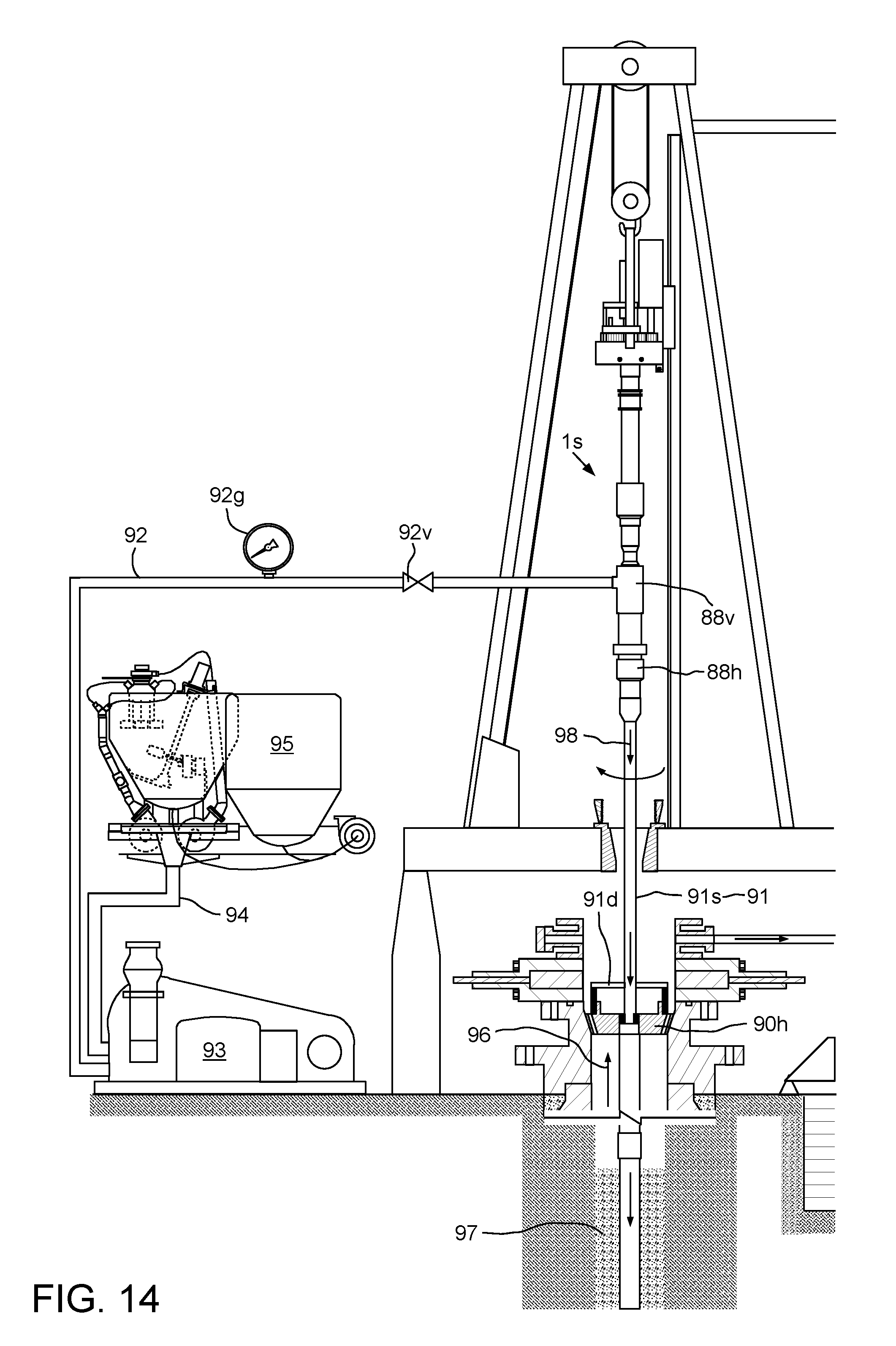
D00015

XML
uspto.report is an independent third-party trademark research tool that is not affiliated, endorsed, or sponsored by the United States Patent and Trademark Office (USPTO) or any other governmental organization. The information provided by uspto.report is based on publicly available data at the time of writing and is intended for informational purposes only.
While we strive to provide accurate and up-to-date information, we do not guarantee the accuracy, completeness, reliability, or suitability of the information displayed on this site. The use of this site is at your own risk. Any reliance you place on such information is therefore strictly at your own risk.
All official trademark data, including owner information, should be verified by visiting the official USPTO website at www.uspto.gov. This site is not intended to replace professional legal advice and should not be used as a substitute for consulting with a legal professional who is knowledgeable about trademark law.