Basket Drawer Structure
Chiang , et al.
U.S. patent number 10,306,982 [Application Number 15/949,239] was granted by the patent office on 2019-06-04 for basket drawer structure. This patent grant is currently assigned to Shen Hao Metal Working Co., Ltd.. The grantee listed for this patent is Shen Hao Metal Working Co., Ltd.. Invention is credited to A-Ming Chiang, Wei-Ching Chiang.


| United States Patent | 10,306,982 |
| Chiang , et al. | June 4, 2019 |
Basket Drawer Structure
Abstract
A basket drawer structure contains: a basket and two rail elements. The basket includes a mesh, a holding space, an opening, and a peripheral rib. The peripheral rib has two recessed portions, two orifices, and two first rollers. The two recessed portions have two shaft holes, and two rivets insert through the two shaft holes to rivet with the two first rollers individually. The two rail elements are symmetrically fixed on a shelf or a cabinet. A distance between the two rail elements is equal to a width of the basket, and the two rail elements respectively include two support rails. Two second rollers are riveted on two front ends of the two support rails individually. The basket is retained in the two support rails by way of the peripheral rib, and the two second rollers of the two rail elements are mounted in the peripheral rib.
| Inventors: | Chiang; A-Ming (Yilan, TW), Chiang; Wei-Ching (Yilan, TW) | ||||||||||
|---|---|---|---|---|---|---|---|---|---|---|---|
| Applicant: |
|
||||||||||
| Assignee: | Shen Hao Metal Working Co.,
Ltd. (Yilan, TW) |
||||||||||
| Family ID: | 61014294 | ||||||||||
| Appl. No.: | 15/949,239 | ||||||||||
| Filed: | April 10, 2018 |
Prior Publication Data
| Document Identifier | Publication Date | |
|---|---|---|
| US 20180338616 A1 | Nov 29, 2018 | |
Foreign Application Priority Data
| May 24, 2017 [TW] | 106207477 U | |||
| Current U.S. Class: | 1/1 |
| Current CPC Class: | A47L 15/501 (20130101); A47F 3/063 (20130101); A47B 88/407 (20170101); A47B 88/427 (20170101); A47B 88/437 (20170101); A47L 15/507 (20130101); A47B 2210/0021 (20130101); A47B 2210/0062 (20130101); A47B 2088/4274 (20170101); A47B 2088/401 (20170101); A47B 2210/0024 (20130101) |
| Current International Class: | A47F 3/06 (20060101); A47B 88/407 (20170101); A47B 88/40 (20170101); A47B 88/437 (20170101); A47B 88/427 (20170101); A47L 15/50 (20060101) |
| Field of Search: | ;211/88.01,126.15,126.9,133.5,133.2,41.4,151,153,181.1,94.02 ;108/30 ;312/334.12,334.1,334.18,334.21,330.1 |
References Cited [Referenced By]
U.S. Patent Documents
| 1748843 | February 1930 | Kuckel |
| 2080885 | May 1937 | Cocks |
| 2103885 | December 1937 | Whalen |
| 3269548 | August 1966 | Geiger |
| 3556625 | January 1971 | Kauffman |
| 4199200 | April 1980 | Livingston |
| 4447095 | May 1984 | Fielding |
| 4595247 | June 1986 | Zank |
| 4913298 | April 1990 | Compagnucci |
| 4995682 | February 1991 | Gutner |
| 5083848 | January 1992 | Merino |
| 5086936 | February 1992 | Remmers |
| 5209555 | May 1993 | Camilleri |
| 5330063 | July 1994 | Remmers |
| 5474378 | December 1995 | Smith |
| 5505534 | April 1996 | Laenn |
| 5810179 | September 1998 | Kleiman |
| 5980009 | November 1999 | Atalla |
| 6039422 | March 2000 | Butters |
| 6148813 | November 2000 | Barnes |
| 6336564 | January 2002 | Garnier |
| 6491173 | December 2002 | Costa |
| 6578720 | June 2003 | Wang |
| D493308 | July 2004 | Nilsson |
| 7108143 | September 2006 | Lin |
| 7168578 | January 2007 | Mersch |
| D546101 | July 2007 | Knight |
| 7406833 | August 2008 | Ertz |
| D628388 | December 2010 | Klein |
| 7857329 | December 2010 | Cai |
| 8157339 | April 2012 | Park |
| 9186038 | November 2015 | Bastuji |
| 9468293 | October 2016 | Yang |
| 9861200 | January 2018 | Lim |
| 2002/0125802 | September 2002 | Remmers |
| 2005/0001522 | January 2005 | Yang |
| 2006/0152118 | July 2006 | Lee |
| 2006/0219271 | October 2006 | Feddema |
| 2007/0235401 | October 2007 | Costa |
| 2008/0054772 | March 2008 | Koloff |
| 2009/0151758 | June 2009 | Kristensson |
| 2012/0139402 | June 2012 | Haidar |
| 2013/0093306 | April 2013 | Shin |
Attorney, Agent or Firm: Kamrath; Alan D. Mayer & Williams PC
Claims
What is claimed is:
1. A basket drawer structure comprising: a basket and two rail elements; with the basket including a mesh formed on a lower end of the basket, a holding space defined in the basket, an opening formed on an upper end of the basket, and a peripheral rib arranged around the opening, with the peripheral rib having square cross sections, with an inner wall of the peripheral rib connecting with the mesh; with the peripheral rib having two recessed portions formed on rear ends of outer sides of the basket, with the two recessed portions having depths, with orifices defined inside the two recessed portions, with two first rollers rotatably riveted on the two recessed portions respectively, wherein the two recessed portions have shaft holes, wherein two rivets insert through the shaft holes to rivet with centers of the two first rollers, wherein the two first rollers are rotatably riveted on the two recessed portions respectively, wherein the two first rollers do not extend over the depths of the two recessed portions; with the two rail elements adapted to be spaced and symmetrically fixed on a cabinet, with a distance between the two rail elements being equal to a width of the basket, wherein the two rail elements respectively include two support rails arranged on inner sides of the two rail elements, with two second rollers riveted on front ends of the two support rails, wherein the basket is retained in the two support rails by way of the peripheral rib, and wherein the two second rollers of the two rail elements are mounted in the peripheral rib.
2. A basket drawer structure comprising: a basket including a mesh formed on a lower end of the basket, a holding space defined in the basket, an opening formed on an upper end of the basket, and a peripheral rib arranged around the opening, with the peripheral rib having square cross sections, with an inner wall of the peripheral rib connecting with the mesh; with the peripheral rib having two recessed portions respectively formed on rear ends of outer sides of the basket, with the two recessed portions having depths, with orifices defined inside the two recessed portions, with two first rollers rotatably riveted on the two recessed portions respectively, wherein the two recessed portions have openings, wherein two rivets insert through the openings to rivet with centers of the two first rollers, and wherein the two first rollers do not extend over the depths of the two recessed portions.
Description
BACKGROUND OF THE INVENTION
Field of the Invention
The present invention relates to a cabinet for accommodating objects (such as clothes) and, more particularly, to a basket drawer which pulls rollers easily.
Description of the Prior Art
A conventional cabinet is applied to accommodate objects and contains a drawer fixed across a rail, so the drawer is pulled difficultly because of pulling resistance. To decrease the pulling resistance, the conventional cabinet contains a drawer, two rails, and two rollers arranged on the two rails respectively, such that the drawer is pulled easily. However, the two rollers are arranged on the two rails respectively, thus occupying storage space and increasing manufacture cost.
A conventional basket drawer contains a hollow accommodation space, and two rollers are arranged on two rails of the cabinet, thus having an unattractive appearance. Furthermore, it is not easy to form the two rails on cables of the basket drawer, so the two rollers are arranged on the two rails of the conventional cabinet. The basket drawer when loaded cannot be pulled easily.
The present invention has arisen to mitigate and/or obviate the afore-described disadvantages.
SUMMARY OF THE INVENTION
The primary objective of the present invention is to provide a basket drawer structure in which a peripheral rib has two recessed portions respectively formed on two rear ends of two outer sides of the basket. Two orifices are defined inside the two recessed portions individually, and two first rollers are rotatably riveted on the two recessed portions respectively. Hence, the two first rollers of the basket correspond to two rail elements respectively, and two second rollers of the two rail elements correspond to the basket, so that the basket is supported and rolls by way of the two first rollers and the two second rollers, thus pulling the basket smoothly.
To obtain the above-mentioned objective, a basket drawer structure provided by the present invention contains: a basket and two rail elements.
The basket includes a mesh formed on a lower end of the basket, a holding space defined in the basket, an opening formed on an upper end of the basket, and a peripheral rib arranged around the opening and to have a square cross section of the peripheral rib. An inner wall of the peripheral rib connects with the mesh. The peripheral rib has two recessed portions respectively formed on two rear ends of two outer sides of the basket. The two recessed portions define two depths, two orifices are defined inside the two recessed portions individually, and two first rollers are rotatably riveted on the two recessed portions respectively. The two recessed portions have two shaft holes defined thereon individually, and two rivets insert through the two shaft holes to rivet with two centers of the two first rollers individually. Hence, the two first rollers are rotatably riveted on the two recessed portions respectively, and the two orifices of the two recessed portions provide two riveting spaces to the two first rollers individually.
The two rail elements are spaced and symmetrically fixed on a shelf or a cabinet. A distance between the two rail elements is equal to a width of the basket. The two rail elements respectively include two support rails arranged on two inner sides of the two rail elements. Two second rollers are riveted on two front ends of the two support rails individually. The basket is retained in the two support rails by way of the peripheral rib, and the two second rollers of the two rail elements are mounted in the peripheral rib.
BRIEF DESCRIPTION OF THE DRAWINGS
FIG. 1 is a perspective view showing the assembly of a basket drawer structure according to a preferred embodiment of the present invention.
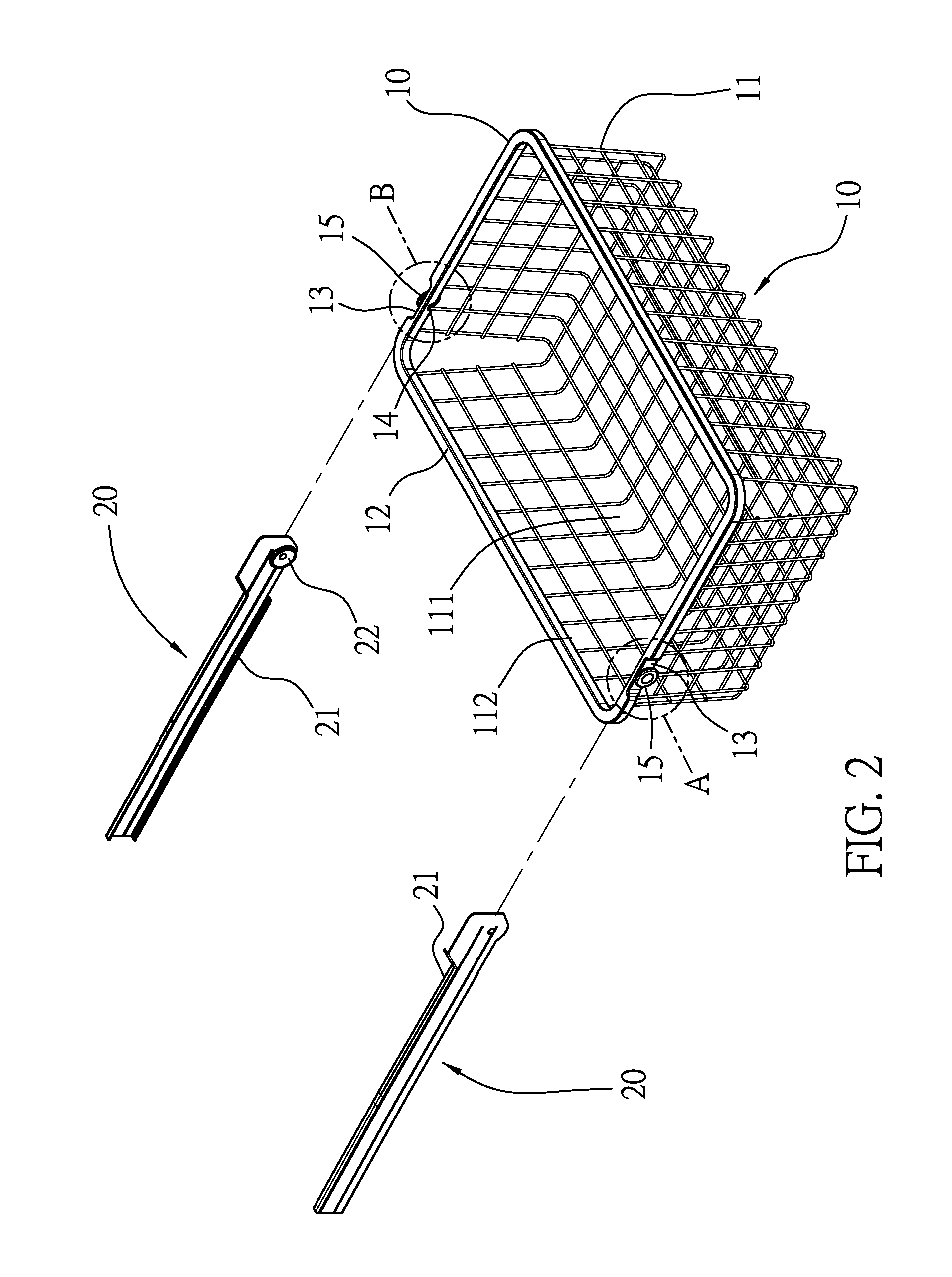
FIG. 2 is a perspective view showing the exploded components of the basket drawer structure according to the preferred embodiment of the present invention.
FIG. 3 is an amplified view of a portion A of FIG. 2.
FIG. 4 is an amplified view of a portion B of FIG. 2.
FIG. 5 is a top elevational view of FIG. 3.
FIG. 6 is a side plan view of FIG. 4.
FIG. 7 is a perspective view showing the assembly of a part of the basket drawer structure according to the preferred embodiment of the present invention.
DETAILED DESCRIPTION OF THE PREFERRED EMBODIMENTS
The present invention will be clearer from the following description when viewed together with the accompanying drawings, which show, for purpose of illustration only, preferred embodiments in accordance with the present invention.
With reference to FIGS. 1 to 4, a basket drawer structure according to a preferred embodiment of the present invention comprises: a basket 10 and two rail elements 20.
The basket 10 includes a mesh 11 formed on a lower end thereof, a holding space 111 defined in the basket 10, an opening 112 formed on an upper end of the basket 10, and a peripheral rib 12 arranged around the opening 112 to have a square cross section of the peripheral rib 12. An inner wall of the peripheral rib 12 connects with the mesh 11. The peripheral rib 12 has two recessed portions 13 respectively formed on two rear ends of two outer sides of the basket 10. The two recessed portions 13 define two depths H0, two orifices 14 are defined inside the two recessed portions 13 individually, and two first rollers 15 are rotatably riveted on the two recessed portions 13 respectively. The two orifices 14 of the two recessed portions 13 provide two riveting spaces to the two first rollers 15 individually.
The two rail elements 20 are spaced and symmetrically fixed on a shelf or a cabinet. A distance between the two rail elements 20 is equal to a width of the basket 10. The two rail elements 20 respectively include two support rails 21 arranged on two inner sides of the two rail elements 20. Two second rollers 22 are riveted on two front ends of the two support rails 21 individually. The basket 10 is retained in the two support rails 21 by way of the peripheral rib 12, and the two second rollers 22 of the two rail elements 20 are mounted in the peripheral rib 12, so that two rail elements 20 support the basket 10. The two first rollers 15 of the basket 10 are accommodated in the two support rails 21, so that the two rail elements 20 support the basket 10.
When the basket 10 is fixed between the two rail elements 20, two front ends of the two rail elements 20 support the basket 10 by using the two second rollers 22, and a rear end of the basket 10 supports the two rail elements 20 by way of the two first rollers 15.
Referring to FIGS. 3-5, the peripheral rib 12 of the basket 10 reinforces the basket 10, and the two recessed portions 13 facilitate accommodation of the two first rollers 15, so that the two first rollers 15 do not extend or do not overly extend out of the two recessed portions 13, thus saving space and reinforcing the basket 10.
As shown in FIGS. 4, 6 and 7, the two recessed portions 13 of the peripheral rib 12 of the basket 10 have two shaft holes 131 defined thereon individually. Two rivets 151 insert through the two shaft holes 131 to rivet with two centers of the two first rollers 15 individually. Two first rollers 15 are rotatably riveted on the two recessed portions 13 respectively, and the two first rollers 15 do not extend over the two depths H0 of the two recessed portions 13 individually
Accordingly, the two first rollers 15 of the basket 10 correspond to the two rail elements 20 respectively, and the two second rollers 22 of the two rail elements 20 correspond to the basket 10, so that the basket 10 is supported and rolls by way of the two first rollers 15 and the two second rollers 22, thus pulling the basket 10 smoothly and saving effort.
While various embodiments in accordance with the present invention have been shown and described, it is clear to those skilled in the art that further embodiments may be made without departing from the scope of the present invention.
* * * * *
D00000
D00001
D00002
D00003
D00004
D00005
D00006
D00007
XML
uspto.report is an independent third-party trademark research tool that is not affiliated, endorsed, or sponsored by the United States Patent and Trademark Office (USPTO) or any other governmental organization. The information provided by uspto.report is based on publicly available data at the time of writing and is intended for informational purposes only.
While we strive to provide accurate and up-to-date information, we do not guarantee the accuracy, completeness, reliability, or suitability of the information displayed on this site. The use of this site is at your own risk. Any reliance you place on such information is therefore strictly at your own risk.
All official trademark data, including owner information, should be verified by visiting the official USPTO website at www.uspto.gov. This site is not intended to replace professional legal advice and should not be used as a substitute for consulting with a legal professional who is knowledgeable about trademark law.