Apparatus and method for modulating data message by employing orthogonal variable spreading factor (OVSF) codes in mobile communication system
Bang , et al.
U.S. patent number 10,305,536 [Application Number 14/484,533] was granted by the patent office on 2019-05-28 for apparatus and method for modulating data message by employing orthogonal variable spreading factor (ovsf) codes in mobile communication system. The grantee listed for this patent is Electronics and Telecommunications Research Institute. Invention is credited to Seung-Chang Bang, Jong Suk Chae, Jae Heung Kim, Jung Im Kim, Tae Joong Kim, Hyuck Jae Lee, Narm Hee Lee, Jae Ryong Shim.


View All Diagrams
| United States Patent | 10,305,536 |
| Bang , et al. | May 28, 2019 |
Apparatus and method for modulating data message by employing orthogonal variable spreading factor (OVSF) codes in mobile communication system
Abstract
A method for converting source data to a channel-modulated signal having a plurality of pairs of in-phase (I) and quadrature-phase (Q) data in a mobile station, wherein the mobile station uses at least one channel, includes the steps of: a) encoding the source data to generate at least one data part and a control part; b) generating at least one spreading code to be allocated to the channel, wherein each spreading code is selected on the basis of a data rate of the data part and the control part and spreading codes are selected so that two consecutive pairs of the I and Q data are correspondent to two points located on same point or symmetrical with respect to a zero point on a phase domain; and c) spreading the control part and the data part by using the spreading code, to thereby generate the channel-modulated signal.
| Inventors: | Bang; Seung-Chang (Daejeon, KR), Kim; Tae Joong (Daejeon, KR), Kim; Jae Heung (Daejeon, KR), Kim; Jung Im (Daejeon, KR), Chae; Jong Suk (Daejeon, KR), Lee; Hyuck Jae (Daejeon, KR), Shim; Jae Ryong (Daejeon, KR), Lee; Narm Hee (Daejeon, KR) | ||||||||||
|---|---|---|---|---|---|---|---|---|---|---|---|
| Applicant: |
|
||||||||||
| Family ID: | 37035130 | ||||||||||
| Appl. No.: | 14/484,533 | ||||||||||
| Filed: | September 12, 2014 |
Prior Publication Data
| Document Identifier | Publication Date | |
|---|---|---|
| US 20150030055 A1 | Jan 29, 2015 | |
Related U.S. Patent Documents
| Application Number | Filing Date | Patent Number | Issue Date | ||
|---|---|---|---|---|---|
| 13972061 | Aug 21, 2013 | ||||
| 13303489 | Nov 23, 2011 | ||||
| 12259072 | Feb 21, 2012 | 8121173 | |||
| 11618361 | Sep 8, 2009 | 7586973 | |||
| 09584189 | Oct 28, 2008 | 7443906 | |||
Foreign Application Priority Data
| May 31, 1999 [KR] | 1999-19813 | |||
| Aug 30, 1999 [KR] | 1999-36383 | |||
| Current U.S. Class: | 1/1 |
| Current CPC Class: | H04J 13/10 (20130101); H04J 13/20 (20130101); H04J 13/0044 (20130101); H04B 1/7073 (20130101); H04B 2201/70703 (20130101) |
| Current International Class: | H04B 1/707 (20110101); H04J 13/20 (20110101); H04J 13/00 (20110101); H04J 13/10 (20110101); H04B 1/7073 (20110101) |
| Field of Search: | ;375/130,140,146,147 |
References Cited [Referenced By]
U.S. Patent Documents
| 5103459 | April 1992 | Gilhousen et al. |
| 5231634 | July 1993 | Giles et al. |
| 5235614 | August 1993 | Bruckert et al. |
| 5381449 | January 1995 | Jasper et al. |
| 5416797 | May 1995 | Gilhousen et al. |
| 5418813 | May 1995 | Schaffner et al. |
| 5442625 | August 1995 | Gitlin et al. |
| 5461610 | October 1995 | Weerackody |
| 5471497 | November 1995 | Zehavi |
| 5537414 | July 1996 | Takiyasu et al. |
| 5546424 | August 1996 | Miyake |
| 5566164 | October 1996 | Ohison |
| 5602833 | February 1997 | Zehavi |
| 5619524 | April 1997 | Ling et al. |
| 5619526 | April 1997 | Kim et al. |
| 5638362 | June 1997 | Dohl et al. |
| 5659573 | August 1997 | Bruckert et al. |
| 5673259 | September 1997 | Quick, Jr. |
| 5712869 | January 1998 | Lee et al. |
| 5727026 | March 1998 | Beukema |
| 5734647 | March 1998 | Yoshida et al. |
| 5751761 | May 1998 | Gilhousen |
| 5790551 | August 1998 | Chan |
| 5809060 | September 1998 | Cafarella et al. |
| 5818867 | October 1998 | Rasmussen et al. |
| 5822311 | October 1998 | Hassan et al. |
| 5828662 | October 1998 | Jalai et al. |
| 5850392 | December 1998 | Wang et al. |
| 5870378 | February 1999 | Huang et al. |
| 5926500 | June 1999 | Odenwalder |
| 5930230 | July 1999 | Odenwalder |
| 5930290 | July 1999 | Zhou et al. |
| 5940434 | August 1999 | Lee et al. |
| 5960029 | September 1999 | Kim et al. |
| 5966373 | October 1999 | Stephenson et al. |
| 5991284 | November 1999 | Willenegger et al. |
| 6009091 | December 1999 | Stewart et al. |
| 6011788 | January 2000 | Hurst et al. |
| 6028888 | February 2000 | Roux |
| 6038455 | March 2000 | Gardner et al. |
| 6044103 | March 2000 | Weaver, Jr. |
| 6047306 | April 2000 | Hikila et al. |
| 6084884 | July 2000 | Adachi |
| 6091757 | July 2000 | Cudak et al. |
| 6091780 | July 2000 | Sointula |
| 6094576 | July 2000 | Hakkinen et al. |
| 6097712 | August 2000 | Secord et al. |
| 6101168 | August 2000 | Chen et al. |
| 6108369 | August 2000 | Ovesjo et al. |
| 6115410 | September 2000 | Naruse |
| 6122310 | September 2000 | Ziemer et al. |
| 6130884 | October 2000 | Sato |
| 6134215 | October 2000 | Agrawal et al. |
| 6141337 | October 2000 | Uta et al. |
| 6163563 | December 2000 | Baker et al. |
| 6181683 | January 2001 | Chevillat et al. |
| 6185246 | February 2001 | Gilhousen |
| 6185258 | February 2001 | Alamouti et al. |
| 6188699 | February 2001 | Lang et al. |
| 6233231 | May 2001 | Felix et al. |
| 6233271 | May 2001 | Jones et al. |
| 6240073 | May 2001 | Reichman et al. |
| 6246697 | June 2001 | Whinnett et al. |
| 6246976 | June 2001 | Mukaigawa et al. |
| 6259724 | July 2001 | Esmailzadeh |
| 6324159 | November 2001 | Mennekens et al. |
| 6381229 | April 2002 | Narvinger et al. |
| 6393047 | May 2002 | Popovic' |
| 6400755 | June 2002 | Harris et al. |
| 6473449 | October 2002 | Cafarella et al. |
| 6501797 | December 2002 | Van der Schaar et al. |
| 6510147 | January 2003 | Sun et al. |
| 6519278 | February 2003 | Hiramatsu |
| 6526065 | February 2003 | Cheng |
| 6560194 | May 2003 | Gourgue et al. |
| 6574211 | June 2003 | Padovani et al. |
| 6577618 | June 2003 | Diachina et al. |
| 6580747 | June 2003 | Lipponen |
| 6650687 | November 2003 | McDonough |
| 6693952 | February 2004 | Chuah et al. |
| 6741550 | May 2004 | Shin |
| RE38603 | September 2004 | Kim et al. |
| RE40385 | June 2008 | Bang et al. |
| 7423989 | September 2008 | Hansen et al. |
| 7443906 | October 2008 | Bang et al. |
| 7577085 | August 2009 | Narashimhan |
| 7586973 | September 2009 | Bang et al. |
| 7995455 | August 2011 | Narashimhan et al. |
| 8121173 | February 2012 | Bang et al. |
| 8213485 | July 2012 | Odenwalder |
| 2001/0026578 | October 2001 | Ando |
| 2003/0147655 | August 2003 | Shattil |
| 2004/0132496 | July 2004 | Kim |
| 2004/0258025 | December 2004 | Li et al. |
| 2005/0054313 | March 2005 | Gummadi et al. |
| 2005/0141407 | June 2005 | Sandhu |
| 2005/0186958 | August 2005 | Hansen et al. |
| 2005/0237919 | October 2005 | Pettendorf |
| 2005/0281354 | December 2005 | Kim |
| 2006/0251193 | November 2006 | Kopmeiners |
| 1133658 | Oct 1994 | CN | |||
| 19708626 | Sep 1998 | DE | |||
| 0783210 | Jul 1997 | EP | |||
| 0 918 410 | Sep 1997 | EP | |||
| 0814581 | Dec 1997 | EP | |||
| 0 921 652 | Oct 1998 | EP | |||
| 2 300 545 | Nov 1996 | GB | |||
| 07038962 | Feb 1995 | JP | |||
| 1966-070265 | Mar 1996 | JP | |||
| 09-312629 | May 1996 | JP | |||
| 1966-172419 | Jul 1996 | JP | |||
| 2815007 | Dec 1996 | JP | |||
| 3409628 | Mar 1997 | JP | |||
| 1997-298490 | Nov 1997 | JP | |||
| 07-312783 | Jun 2009 | JP | |||
| 1996-0000460 | Feb 1992 | KR | |||
| 1997-0031399 | Jun 1997 | KR | |||
| 0155510 | Jul 1997 | KR | |||
| 1997-0072739 | Nov 1997 | KR | |||
| 0155510 | Jul 1998 | KR | |||
| 10 0298340 | May 2001 | KR | |||
| WO 92/17011 | Oct 1992 | WO | |||
| WO 95/03652 | Feb 1995 | WO | |||
| WO 95/12937 | May 1995 | WO | |||
| WO 1997/000568 | Jan 1997 | WO | |||
| WO 97-33400 | Sep 1997 | WO | |||
| WO 97/45970 | Dec 1997 | WO | |||
| WO 97/47098 | Dec 1997 | WO | |||
| WO 1997/046041 | Dec 1997 | WO | |||
| WO 1998/018280 | Apr 1998 | WO | |||
| WO 1999/003224 | Jul 1998 | WO | |||
| WO 1999/003225 | Jul 1998 | WO | |||
| WO 1999/003224 | Jan 1999 | WO | |||
| WO 1999/003225 | Jan 1999 | WO | |||
| WO 99/38337 | Jul 1999 | WO | |||
| WO 00/13431 | Aug 1999 | WO | |||
| WO 99/59265 | Nov 1999 | WO | |||
| WO 00/42752 | Jan 2000 | WO | |||
| WO 00/13431 | Mar 2000 | WO | |||
| WO 2005/006700 | Jan 2005 | WO | |||
Other References
|
Edited by Matsushita; UTRA Physical Layer Description, TDD parts for public operation; Layer 1 Expert Group meeting, Bocholt May 18-20; Nov. 13, 1998; pp. 1-27. cited by applicant . Shim, et al.; Spectrally Efficient Modulation and Spreading Scheme for CDMA Systems; Nov. 12, 1998 Electronics Letters; vol. 34, pp. 2210-2211. cited by applicant . Ericsson, "Uplink channelization code allocation in UTRA/FDD, Decision", TSG-RAN Working Group 1 meeting #6, TSGR1#6(99)845, Espoo, Finland, Jul. 13-16, 1999, pp. 1-6. cited by applicant . ETRI, "Channelization code allocation in uplink multi-code transmissions, Decision", TSG-RAN Working Group 1 meeting #6, TSGR1#6(99)828, Espoo, Finland, Jul. 13-16, 1999, pp. 1-6. cited by applicant . 3.sup.rd Generation Partnership Project (3GPP), Technical Specification Group (TSG), Radio Access Network (RAN); Working Group 1 (WG1); Spreading and Modulation (FDD), TS 25.213,V2.0.0 (Apr. 1999), pp. 1-26. cited by applicant . 3.sup.rd Generation Partnership Project (3GPP), Technical Specification Group (TSG), Radio Access Network (RAN); Working Group 1 (WG1); Spreading and Modulation (FDD), TS 25.213,V2.1.0 (Jun. 1999), pp. 1-26. cited by applicant . CESM/Pro Telecom, et al., "FMA-FRAMES Multiple AccessA Harmonized Concept for UMTS/IMT-2000; FMA2-Wideband CDEMDA", Homepage: http://WWW.de.infowin.org/ACTS/RUS/Projects/Frames, pp. 1-14. cited by applicant . Birgenheier, Raymond a.; "Overview of Code-Domain Power, Timing, and Phase Measurements"; Hewlett;Packard Journal: vol. 47, No. 1, pp. 73-93; (Feb. 1996). cited by applicant . INSPEC Abstract Accession No. 6468729 and "3.sup.rd CDMA International Conference and Exhibition," pbulished 1998, ETRI, pp. 101-105, vol. 2, Bang et al. "A Spectrally Efficient Modulation and Spreading Scheme Using Orthogonal Channelization and Rotator". cited by applicant . Laird, et al. "A Peak-to-Average Power Reduction Method for Third Generation CDMA Reverse Links," IEEE Vehicular Technology Conference, vol. 1, pp. 551-555, May 16, 1999. cited by applicant . Lee, et al. "Direct Sequence Spread Spectrum Walsh-QPSK Modulation," IEEE Transactions on Communications, Vo. 46, No. 9, Sep. 1998. cited by applicant . UMTS Layer 1 Expert Group Meeting, tdoc120, Bocholt, May 18-20, 1998, pp. 2-27, et al. "Direct Sequence Spread Spectrum Walsh-QPSK Modulation," IEEE Transactions on Communications, vol. 46, No. 9, Sep. 1998. cited by applicant . Request for Reexamination of U.S. Pat. No. 5,960,029 Filed Mar. 16, 2009. cited by applicant . Request for Reexamination of U.S. Pat. No. Re. 40,385, Filed Mar. 16, 2009. cited by applicant . United States Patent & Trademark Office Communication, "Decision Sua Sponte Vacating Inter Parties Reexamination Filing Date", Control No. 95/000,454 dated May 27, 2009. cited by applicant . Publication No. 1019950054532 Filed Jul. 31, 1997. cited by applicant . "Physical Layer Standard for cdma2000 Spread Spectrum Systems", Release A, 3GPP2 C.S0002-A, Jun. 9, 2000. cited by applicant . TIA/EIA PN-3241 Ballot Version, "Mobile Station--Base Station Compatibility Standard for Dual-Mode Wideband Spread Spectrum Cellular System". cited by applicant . "Peak to Peak Average Power Reduction Method for 3G Reverse Link", submitted to the Telecommunications Industry Association TR45.5 Standards Committee Jan. 26, 1998. cited by applicant . Figure 1 of U.S. Pat. No. Re. 40385, Published Jun. 17, 2008. cited by applicant . Ovesjo et al., "FRAMES Multiple Access Mode 2-Wideband CDMA," IEEE (1997). cited by applicant . "FDD Mode Uplink OVSF Choice," TSG-RAN Working Group 1 Meeting #5, Source: Motorola (1999). cited by applicant . TSG-RAN Working Group 1 Meeting #5, Agenda Item: 10 and 11, Ad hoc # 10 (1999). cited by applicant . WCDMA/NA, T1P1--Wireless/Mobile Services and Systems Technical Sub-Committee, IMT-2000 Radio Transmission Technology Candidate (1998). cited by applicant . Technical Specification: 3.sup.rd Generation Partnership Project; Tech. Spec. Group Radio Access Network; Physical Channels and Mapping of Transport Channels onto Physical Channels (FDD) (3G TS 25.211 version 3.0.0) (1999). cited by applicant . Technical Specification: 3.sup.rd Generation Partnership Project (3GPP); Tech. Spec. Group (TSG) Radio Access Network (RAN); Working Group 1 (WG1); Multiplexing and Channel Coding (FDD) (TS 25.212) (1999). cited by applicant . Technical Specification: 3.sup.rd Generation Partnership Project; Tech. Spec. Group Radio Access Network, Multiplexing and Channel Coding (FDD) (3G TS 25.212 version 3.0.0) (1999). cited by applicant . Technical Specification: 3.sup.rd Generation Partnership Project (3GPP); Tech. Spec. Group (TSG) Radio Access Network Spreading and Modulation (FDD) (3G TS 25.213 version 3.0.0) (1999). cited by applicant . Technical Specification: 3.sup.rd Generation Partnership Project (3GPP); Tech. Spec. Group (TSG) Radio Access Network (RAN); Working Group 1 (WG1); Physical Channels and mapping of Transport Channels onto Physical Channels (FDD) (1999). cited by applicant . 3GPP (S1.13) 3Gpp FDD, spreading and Modulation Specification (1999). cited by applicant . Freiberg et al., "Crest Factor Reduction Using Orthogonal Spreading Codes in Multi-Carrier CDMA Systems," IEEE (1997). cited by applicant . 4.sup.th ARIB-TTA Meeting on IMT-2000 Standardization (1998). cited by applicant . Amplitude Differences Between Uplink DPCCH and DPDCHs, TSG-RAN Working Group 1 Meeting # 4, Source: Ericsson (1999). cited by applicant . Lang et al., "Comparison of Correlation Parameters of Binary Codes for DS/CDMA Systems," IEEE (1994). cited by applicant . Garg et al., "Third Generation (3G) Communications Systems," IEEE (1999). cited by applicant . Dasilva et al., "Multicarrier Orthogonal CDMA Signals for Quasi-Synchronous Communication Systems," III Journal on Selected Areas in Communications, vol. 12, No. 5, Jun. 1994. cited by applicant . Popovic, Efficient Despreaders for Multi-Code CDMA Systems, IEEE (1997). cited by applicant . Yip et al., "Performance Sensitivity of Quasi-Synchronous, Multicarrier DS-CDMA Systems due to Carrier Frequency Disturbance," IEEE, International Conference on Communication Tech. (1998). cited by applicant . Bang et al., "Performance Analysis of a Wideband CDMA System for FPLMTS," IEEE (1997). cited by applicant . Zhang et al., "A Sequency Multiplexing Technique for Mobile Communication Systems" (1993). cited by applicant . IMT-2000 Cooperative Activities between ARIB and TTA [Draft] (2000). cited by applicant . Ochiai et al., "OFDM-CDMA with Peak Power Reduction Based on the Spreading Sequences", Institute of Industrial Science, University of Tokyo, IEEE (1998). cited by applicant . Defendants' Final Disclosures Under Patent Local Rule 3.6(b) relating to U.S. Pat. No. Re. 40,253, dated Jun. 15, 2012, SPH America, LLC v. Acer, Inc. et al., Civil Action No. 3:09-cv-02535-CAB (KSC) (S.D. Cal.). cited by applicant . RA-99183[1] 3GPP(S1.13) V1.0.1, "EGPP FDD, Spreading and Modulation Specification", Mar. 1999. cited by applicant . R1-99347 TSGR1 #4 (99) 347 TSGR1 #4(99) 347, "Amplitude Differences Between Uplink DPCCH and DPDCHs", TGS-RAN Working Group 1, Meeting #4, Apr. 18-20, 1999, Shin-Yokohama, Japan. cited by applicant . "RP#3(99)234, TSGR1#4(99)5, TS25.211 V2.0.0 (Apr. 1999), 3rd Generation Partnership Project (3GPP); Technical Specification Group (GSG), Radio Access Network (RAN); Working Group 1 (WG1); Physical Channels and Mapping of Transport Channels Onto Physical Channels" Apr. 1999. cited by applicant . "TSG1 #4(99) 526, TS 25.212 V1.0.0, 3rd Generation Partnership Project (3GPP) Technical Specification Group (TSG), Radio Access Network (RAN); Working Gropu 1 (WG1), Multiplexing and Channel Coding (FDD)", Apr. 1999. cited by applicant . Prasad, Ramjee et al., "An Overview of CDMA Evolution Toward Wideband CDMA", Fourth Quarter 1998, IEEE Communication Surveys. cited by applicant . Durrani et al., "Sequential Generation of Binary Orthogonal Functions", Electronics Letters, pp. 377-380, vol. 7, No. 13, May 19, 1971. cited by applicant . U.S. Appl. No. 60/077,741, filed Mar. 12, 1998, Chuah. cited by applicant . U.S. Appl. No. 60/528,169, filed Dec. 9, 2003, Kopmeiners. cited by applicant . U.S. Appl. No. 60/483,719, filed Jun. 30, 2003, Kopmeiners. cited by applicant . U.S. Appl. No. 60/581,122, filed Jun. 18, 2004, Kim. cited by applicant . U.S. Appl. No. 60/059,016, filed Sep. 16, 1997, Alamouti et al. cited by applicant . U.S. Appl. No. 60/059,219, filed Sep. 18, 1997, Alamouti et al. cited by applicant . U.S. Appl. No. 60/063,780, filed Oct. 31, 1997, Alamouti et al. cited by applicant . Exhibit F4--Invalidity Claim Chart for U.S. Pat. No. Re. 44,530 vs. U.S. Pat. No. 6,181,683 ("Chevillat"), 28 pgs. cited by applicant . Laird, et al. "A Peak-to-Average Power Reduction Method for Third Generaion Reverse Link", TIA TR45.5 submission TR45.5.4./98.01.26.08, Jan 26, 1998. cited by applicant . Kevin Laird & Tyler Brown, "Analysis of Hybrid PSK Spreading Method for Peak-to-Average Reduction of the 3G Reverse Link," TIA TR 45.5.4/98 submission, Feb. 17, 1998. cited by applicant . Motorola, "W-CDMA Uplink Spreading and Modulation," Tdoc SMG2 45/98, Sophia Antipolis Mar. 3-6, 1998. cited by applicant . S.R. Kim et al., "A Coherent Dual-Channel QPSK Modulation for CDMA Systems," IEEE 46th Vehicular Tech. Conf. at 1848-1852, Apr. 28-May 1, 1996. cited by applicant . TTA Proposal I System Description Draft 0.0, dated Mar. 25, 1998. cited by applicant . TTA Proposal II: Asynchronous Wideband Direct-Sequence CDMA System for IMT-2000 RTT system Description (Ver. 0.0). cited by applicant . "FMA-FRAMES Multiple Access: A Harmonized Concept for UMTS/IMT-2000" in "ITU Workshop on IMT-2000 Transmission Technologies," Toronto Sep. 10-11, 1997 (CSEM/Pro Telecom, Ericsson, France Telecom-CNET, Nokia, Siemens). cited by applicant . 4th TTA-ARIB Meeting on IMT-2000 Standardization Documents, Apr. 6-7, 1998. cited by applicant . DaSilva et al., "Multicarrier Orthogonal CDMA Signals for Quasi-Synchronous Communications Systems," IEEE J. on Selected Areas in Communications, vol. 12, No. 5 pp. 842-852 (1994). cited by applicant . Freiberg et al., "Crest Factor Reduction Using Orthogonal Spreading Codes in Multi-Carrier CDMA Systems" IEEE pp. 120-124 (1997). cited by applicant . Garg, et al., "Third Generation (3G) Mobile Communications Systems," 1999 IEEE Int'l Conf. on Personal Wireless Communication (Feb. 17-19, 1999). cited by applicant . Lang et al., "Comparison of Correlation Parameters of Binary Codes for DS/CDMA Systems," Singapore ICCS '94 Conf. Proc. (1994). cited by applicant . 3GPP, 3G TS 25.212 V3.0.0 (Oct. 1999), 3.sup.rd Generation Partnership Project (3GPP); Technical Specification Group Radio Access Network; Multiplexing and Channel Coding (FDD), Oct. 1999. cited by applicant . 3GPP, 3G TS 25.213 V3.0.0 (Oct. 1999), 3.sup.rd Generation Partnership Project (3GPP); Technical Specification Group Radio Access Network; Spreading and Modulation (FDD), Oct. 1999. cited by applicant . 3GPP, 3GPP (S1.13) v1.0.1 Mar. 1999 ("3GPP FDD, spreading and modulation specification"), TSGR1#3(99) 183 (Mar. 1999). cited by applicant . Bang et al., "Performance Analysis of a Wideband CDMA System for FPLMTS," IEEE 47th Vehicle Technology Conference, 1997, pp. 830-834 (1997). cited by applicant . Chih-Lin et al., "Performance of Multi-Code CDMA Wireless Personal Communications Networks," 1995 IEEE 45th Vehicle Technology Conference, pp. 907-911. cited by applicant . IMT Cooperative Activities between ARIB and TTA [Draft], Apr. 6-7, 1998. cited by applicant . Ovesjo, et al., "FRAMES Multiple Access Mode 2--Wideband CDMA," 1997 8th IEEE International Symposium on Personal, Indoor and Mobile Radio Communications, Waves of the Year 2000, PIMRC '97, pp. 42-46), 1997. cited by applicant . Pursley, et al., "Frequency-hop signaling and multiple packets per transmission for store and forward packet radio networks," Military Communications Conference, 1994. MILCOM '94. Conference Record, 1994 IEEE , pp. 168,172, vol. 1, Oct. 1992. cited by applicant . Chung et al. "Packet synchronization and identification for incremental redundancy transmission in FH-CDMA systems," Personal, Indoor and Mobile Radio Communications, 1992. Proceedings, PIMRC '92., Third IEEE International Symposium on, pp. 292,295, Oct. 19-21, 1992. cited by applicant . ANSI/ATIS, PN-3452 (to be published as IS-95-A), "TR45 Mobile Station--Base Station Computability Standard for Dual-Mode Wideband Spread Spectrum Cellular System" (Ballot Version), Dec. 1994. cited by applicant . Gesbert, et al., From Theory to Practice: An Overview of MIMO Space-Time Coded Wireless Systems, IEEE Journal on Selected Areas in Communications, vol. 21, No. 3, Apr. 2003. cited by applicant . Jeon et al., "Optimal Combining of STBC and Spatial Multiplexing for MIMO-OFDM," IEEE 802.11-03/0513r0, pp. 1-14, Jul. 2003. cited by applicant . Liu et al., "A MIMO System With Backward Compatibility for OFDM Based WLANs," 2003 4th IEEE Workshop on Signal Processing Advances in Wireless Communications, pp. 130-134, 2003. cited by applicant . Petre, et al., "MIMO-OFDM for High-Speed WLANs," IEEE 802.11-04/0136-00-000n, pp. 1-19, Jan. 2004. cited by applicant . Mahadevappa, R., et al., Tgn, et al. "Receiver Sensitivity Tables for MIMOOFDM 802.11n," IEEE 802.11-03/845r0, pp. 1-39, Nov. 2003. cited by applicant . Mujtaba et al., "TGn Sync Proposal Technical Specification," IEEE 802.11-04/889r0, pp. 1-135, Nov. 2004. cited by applicant . IEEE, "Part 11: Wireless LAN Medium Access Control (MAC) and Physical Layer (PHY) specification: High-speed Physical Layer in the 5 GHZ Band," IEEE Std 802-11a-1999. cited by applicant . IEEE Draft Standard 802.11g (2002) Supplements to the ANSI/IEEE Standard 802.11, 1999. cited by applicant . Part 16: Air Interface for Fixed Broadband Wireless Access Systems--Amendment 2: Medium Access Control Modification and Additional Physical Layer Specifications for 2-11 GHz, IEEE Std 802.16a-2003, Apr. 1, 2003. cited by applicant . Part 16: Air Interface for Fixed Broadband Wireless Access Systems--IEEE Std 802.16-2004, Oct. 1, 2004. cited by applicant . Dias, et al., "MTMR Channel Estimation and Pilot Design in the Context of Space-Time Block Coded OFDM-Based WLANs," IST Mobile & Wireless Telecommunications, pp. 73-77, 2002. cited by applicant . Bauch, Space-Time Block Codes Versus Space-Frquency Block Codes (IEEE 2003) ("Bauch"), 2003. cited by applicant . 3GPP, RP#3(99)234, TSGR1#4(99)5, TS 25.211 V2.0.0 (Apr. 1999), 3.sup.rd Generation Partnership Project (3GPP); Technical Specification Group (TSG) Radio Access Network (RAN); Working Group 1 (WG1); Physical Channels and Mapping of Transport Channels Onto Physical Channels, Apr. 1999. cited by applicant . UTRA ETSI SMG2, "The ETSI UMTS Terrestrial Radio Access (UTRA) ITU-R RTT Candidate submission", 1998. cited by applicant . UTRA ETSI SMG/Sumbission of Proposed Radio Transmission Technologies Concept Group Delta--Wideband TDMA/CDMA, Evaluation Document, Tdoc SMG2 /97. cited by applicant . Dianan, E., et al. "Spreading Codes for Direct Sequence CDMA and Wideband CDMA Cellular Networks," IEEE Communications Magazine (Sep. 1998), pp. 48-54. cited by applicant . Lee, D. W., et al., "Development of the Base Station Transceiver Subsystem in the CDMA Mobile System," ETRI Journal, vol. 19, No. 3, Oct. 1997, pp. 116-140. cited by applicant . Fong, M. H., "Concatenated Orthogonal/PN Spreading Sequences and Their Application to Cellular DS-CDMA Systems with Integrated Traffic", IEEE Journal on Selected Areas in Communications, vol. 14, No. 3, Apr. 1996, pp. 547-558. cited by applicant . ETSI SMG Meeting No. 24, Madrid, Spain, Dec. 15-19, 1997--Tdoc SMG 905/97--Concept Group Alpha--Wideband Direct-Sequence CDMA (WCDMA) Evaluation Document (3.0)--Part 2: Annex 1 Answers, Link Budget Calculation Complexity and dual mode GSM/UMTS terminal complexity analysis Rate Matching Principle, pp. 1-39. cited by applicant . ETSI SMG Meeting No. 24, Madrid, Spain, Dec. 15-19, 1997--Tdoc SMG 905/97--Concept Group Alpha--Wideband Direct-Sequence CDMA (WCDMA) Evaluation Document (3.0)--Part 3: Detailed simulation results and parameters, pp. 1-31. cited by applicant . Adachi, F., et al. "Tree-structured generation of orthogonal spreading codes with different lengths for forward link of DS-CDMA mobil radio", Electronics Letters, 2.sup.nd Jan. 1997, vol. 33, No. 1, pp. 27-28. cited by applicant . Holma, H. et al. Cellular Coverage Analysis of Wideband MUD-CDMA System, IEEE, 1997, pp. 549-553. cited by applicant . Povey, G. Jr, TDD-CDMA Extension to FDD-CDMA Based Third Generation Cellular System, IEEE, 1997, pp. 813-817. cited by applicant . Gustafsoon, M., et al., "Compressed Mode Techniques for Inter-Frequency Measurements in a Wide-band DS-CDMA System", IEEE 1997, pp. 231-235. cited by applicant . Japan's Proposal for Candidate Radio Transmission Technology on IMT-2000: W-CDMA, ARIB IMT-2000 Study Committee, Association of Radio Industries and Businesses (ARIB) Japan, Jun. 1998, pp. 1-244. cited by applicant . Kim, Y. H., et al., "Korea Telecom IMT-2000 Testbed Based on Wideband CDMA Technologies", Reprinted from ACTS Mobile Communications Summit 1998, Rhodes, Greece, Jun. 1998, pp. 6 pgs. cited by applicant . Latva-aho, M., "Bit Error Probability Analysis for FRAMES WCDMA Downlink Receivers", IEEE Transactions on Vehicular Technology, vol. 47, No. 4, Nov. 1998, pp. 1119-1133. cited by applicant . Dahlman, E., et al., "UMTS/IMT-2000 Based on Wideband CDMA", IEEE Communications Magazine, Sep. 1998, pp. 70-80. cited by applicant . Raitola, M. et al. "Wideband CDMA Packet Data with Hybrid ARQ", IEEE 1998, pp. 318-322. cited by applicant . 3rd Generation Partnership Project (3GPP) Technical Specification Group (TSG), Radio Access Network (RAN); Working Group 1 (WG1), Physical channels and mapping of transport channels onto physical channels (TDD), TSGR#3(99) 238, TS S1.21 V2.0.0, TSG-RAN meeting #3, Yokohama, Japan, Apr. 21-23, 1999, pp. 1-23. cited by applicant . "Proposal for 3GPP baseband key characteristics", TSG-RAN Working Group 1 meeting #2, TSGR1#2(99)071, Feb. 1999, 8 pgs. cited by applicant . Mitra, U., "Comparison sof Maximum-Likelihood-Based Detection for Two Multirate Access Schemes for CDMA Signals", IEEE Transactions on Communications, vol. 47, No. 1, Jan. 1999, pp. 64-77. cited by applicant . Kamar, S. et al., "High Data-Rate Packet Communications for Cellular Networks Using CDMA: Algorithms and Performance", IEEE Journal on Selected Areas in Communications, vol. 17, No. 3, Mar. 1999, Jan. 2, 2017. cited by applicant . Ottosson, T., et al. "The Impact of Using Multicode Transmission in the WCDMA System", IEEE, 1999 49.sup.th Vehicular Technology Conference, Houston, Texas, USA, May 16-20, pp. 1500-1554. cited by applicant . Gurbuz, O., et al., A Resource Management Framework for QOS Provisioning in W-CDMA Systems, IEEE, 1999, pp. 407-411. cited by applicant . Johnsson, A. L., "Group Wise Successive Interference Cancellation in Multirate CDMA Systems", IEEE, 1999, pp. 1435-1439. cited by applicant . Alam, M., et al., "Impact of Timing Error on the Performance of Multiuser Detection in Multirate CDMA Systems", IEEE, 1999, pp. 299-303. cited by applicant . 3.sup.rd Generation Partnership Project (3GPP); Technical Specification Group (TSG) Radio Access Network (RAN); Working Group 1 (WG1); Physical channels and mapping of transport channels onto physical channels (FDD), RP#3(99)234, TSGR1#4(99)527, TS 25.211 V2.0.0), (Apr. 1999), 28 pgs. cited by applicant . Ochiai et al., "OFDM-CDMA with Peak Power Reduction Based on Spreading Sequences," IEEE Int'l Conference on Communications, vol. 3, pp. 1299-1303 (1998). cited by applicant . Popovic, "Efficient Despreaders for Multi-Code CDMA Systems," Proc. of the ICUPC '97, Oct. 12-16, 1997. cited by applicant . 3GPP, R1-99347 TSGR1#4(99)347 Apr. 18-20, 1999. cited by applicant . Yip et al., "Performance of Sensitivity of Quasi-Synchronous Multi-Carrier DS-CDMA Systems Due to Carrier Frequency Disturbance," Int'l Conf. on Communication Technology, ICCT '98, Oct. 22-24, Beijing, China pp. S32-02-01 to S32-02-5, Oct. 22-24, 1998. cited by applicant . Zhang et al., "A Sequency Multiplexing Technique for Mobile Communication Systems," 1993 International Conference on Information Engineering '93. `Communications and Networks for the Year 2000`, Proceedings of IEEE Singapore International Conference on, pp. 226-230 (1993). cited by applicant . 3GPP TS 25.213, V.2.0.0 (Apr. 1999), 3.sup.rd Generation Partnership Project (3GPP); Technical Specification Group (TSG) Radio Access Network (RAN); Working Group 1 (WG1); Spreading and Modulation (FDD), Apr. 23, 1999. cited by applicant . Motorola, FDD Mode Uplink OVSF Code Choice, TSGR1#5(99)620, Cheju, Korea, Jun. 1-4, 1999. cited by applicant . 3GPP, TSG-RAN Working Group 1 Ad Hoc Committee 10, Ad Hoc #10 Report, TSGR1#5(99)726, Cheju, Korea Jun. 1-4, 1999. cited by applicant . 3GPP, TSGR1#4(99) 526, TS 25.212 V1.0.0, 3rd Generation Partnership Project (3GPP) Technical Specification Group (TSG), Radio Access Network (RAN); Working Group 1 (WG1), Multiplexing and Channel Coding (FDD), Apr. 1999. cited by applicant . Youn, W. S., et al. "A Multi-Carrier CDMA System Using a Concatenated Orthogonal/PN Spreading Scheme", IEEE, 1996, pp. 202-205. cited by applicant . Mueller, T., et al. "Performance of Coherent OFDM-CDMA for Broadband Mobil Communication", Wireless Personal Communications No. 2, 1996, pp. 295-305. cited by applicant . Slimane, S. B., "MC-CDMA with Quadrature Spreading over Frequency Selective Fading Channels", IEEE, 1997, 6 pgs. cited by applicant . Okawa, K., et al. "Orthogonal Multi-Spreading Factor Forward Link for Coherent DS-CDMA Mobil Radio", IEEE, 1997, 6 pgs. cited by applicant . Baier, A. et al. "Multi-Rate DS-CDMA Radio Interface for Third-Generation Cellular Systems", Mobile and Personal Communication 13-15, Dec. 1993, Conference Publication No. 387, IEE 1993, pp. 255-260. cited by applicant . McTiffin, M. J., et al. Mobile Access to an ATM Network Using a CDMA Air Interface, IEEE Journal, on Selected Areas in Communications, vol. 12, No. 5, Jun. 1994, pp. 900-908. cited by applicant . Arad, M. A., et al., Scheduled CDMA: A Hybrid Multiple Access for Wireless ATM Networks, IEEE, 1996, pp. 913-917. cited by applicant . Dahlman, E., et al. "Wide-band services in a DS-CDMA based FPLMTS system" IEEE, 1996 pp. 1656-1660. cited by applicant . ETSI SMG Meeting No. 24, Madrid, Spain, Dec. 15-19, 1997--Tdoc SMG 905/97--Concept Group Alpha--Wideband Direct-Sequence CDMA (WCDMA) Evaluation Document (3.0)--Part 1: System Description Performance Evaluation, pp. 1-53. cited by applicant . "Uplink Channelization Code Allocation in UTRA/FDD", TSG-RAN Working Group 1 meeting #6 TSGR1#1(99)845, Jul. 1999, pp. 1-6. cited by applicant . Gutierrez, A., et al., "Performance of Simultaneous Voice and Data for the IS-95-B Reverse Link", IEEE 1999, pp. 35-38. cited by applicant . Murase, A. "Idle-Signal Casting Multiple Access with Collision Detection (ICMA-CD) for Land Mobile Radio", IEEE Transactions on Vehicular Technology, vol. VT-36, No. 2, May 1987, pp. 45-50. cited by applicant . "Draft Text of W-CDMA PCS Standard", Joint Technical Committed on Wireless Access--JTC(AIR) Standards Contribution, JTC(AIR)/May 9, 1994. cited by applicant . Toshimitsu, K., et al., "A Novel Spread Slotted Aloha System with Channel Load Sensing Protocol", IEEE Journal on Selected Areas in Communications, vol. 12, No. 4, May 1994, pp. 665-672. cited by applicant . Aoki, T., et al., "New preamble structure for AGC in a MIMO-OFDM system", doc.:IEEE 802.11-04/046rl, Jan. 2004, pp. 13. cited by applicant . Tarokh, V., et al., "Space-Time Block Codes from Orthogonal Designs", IEEE Transactions on Information Theory, vol. 45, No. 5, Jul. 1999, pp. 1456-1467. cited by applicant . Kim, T. J., et al., "On Performance Improvements of Spread Slotted ALOHA Network with CLSP/CC", IEICE Trans. Fundamentals. vol. E-80-A., No. 12 Dec. 1997, pp. 2493-2499. cited by applicant . 3.sup.rd Generation Partnership Project; Technical Specification Group Radio Access Network; Physical channels and mapping of transport channels onto physical channels (FDD)"(3G TS 25.211 version 3.0.0"), (Oct. 1999), 35 pgs. cited by applicant. |
Primary Examiner: Burd; Kevin M
Parent Case Text
RELATED APPLICATIONS
This patent application is a Continuation of U.S. patent application Ser. No. 13/972,061, filed Aug. 21, 2013, which is a continuation of U.S. patent application Ser. No. 13/303,489, filed Nov. 23, 2011, which is a continuation of Ser. No. 12/259,072, filed on Oct. 27, 2008, which is a continuation of U.S. patent application Ser. No. 11/618,361, filed on Dec. 29, 2006, which is a continuation of U.S. patent application Ser. No. 09/584,189, filed on May 31, 2000, which claims priority to and the benefit of Korean Patent Application No. 1999-19813, filed on May 31, 1999, and Korean Patent Application No. 1999-36383, filed on Aug. 30, 1999, all of which are hereby incorporated by reference in their entirety.
Claims
What is claimed is:
1. A mobile station capable of using a plurality of data channels and a control channel, comprising: an encoder that encodes source data to generate a plurality of data parts and a control part, wherein the data parts are allocated to the data channels and the control part is allocated to the control channel; a code generator that generates spreading codes to be allocated to the channels, wherein each of the spreading codes is generated on the basis of a spreading factor related to a data rate for the respective channel and a code number for the respective channel; a spreader that spreads the control channel and the data channels using the allocated spreading codes to thereby generate channel-modulated signals; and a gain adjuster that adjusts gains of the channel-modulated signals, wherein: the spreading codes correspond to orthogonal variable spreading factor (OVSF) codes, the spreading code allocated to the control channel is represented by C.sub.256,0, where 256 denotes the spreading factor and 0 the code number, the spreading codes allocated to first and second data channels of the plurality of data channels are represented by C.sub.4,1, the code generator comprises: a counter that consecutively produces a count value in synchronization with a clock signal, a first spreading code generator responsive to the count value and the spreading factor for the respective data channel that generates the spreading code to be allocated to the respective data channel, and a second spreading code generator responsive to the count value and the spreading factor for the control channel that generates the spreading code to be allocated to the control channel, and the first spreading code generator comprises a first logical operator that is configured to perform a first logical operation to generate the spreading code to be allocated to the respective data channel based on the count value, the spreading factor for the respective data channel and the code number for the respective data channel, wherein the first logical operation is .times..times..sym. ##EQU00003## wherein the count value is B.sub.i, the code number for the respective data channel is I.sub.i, the spreading factor for the respective data channel is 2.sup.N, and N is an integer between 2 and 8.
2. The mobile station of claim 1, wherein the first spreading code generator further comprises a first multiplexer that outputs the spreading code to be allocated to the respective data channel in response to a first select signal.
3. The mobile station of claim 1, wherein the second spreading code generator comprises: a second logical operator that is configured to generate the spreading code to be allocated to the control channel by performing a second logical operation based on the count value, the spreading factor for the control channel and the code number for the control data channel, and a second multiplexer that outputs the spreading code to be allocated to the control channel in response to a second select signal.
4. The mobile station of claim 3, wherein the second logical operation is .times..times..sym. ##EQU00004## wherein the count value is B.sub.i, the code number for the control channel is I.sub.i, the spreading factor for the control channel is 2.sup.N, and N is an integer between 2 and 8.
5. The mobile station of claim 4, wherein C.sub.4,1 represents {1, 1, -1, -1}.
6. The mobile station of claim 5, wherein the spreading code generator further comprises a controller responsive to the spreading factors for the channels that generates the code numbers for the channels.
7. A communication method for a mobile station capable of using a plurality of data channels and a control channel, comprising: encoding source data to generate a plurality of data parts and a control part, wherein the data parts are allocated to the data channels and the control part is allocated to the control channel; generating spreading codes to be allocated to the channels, wherein each of the spreading codes is generated on the basis of a spreading factor related to a data rate for the respective channel and a code number for the respective channel; spreading the control channel and the data channels using the allocated spreading codes to thereby generate channel-modulated signals; and adjusting gains of the channel-modulated signals, wherein: the spreading codes correspond to orthogonal variable spreading factor (OVSF) codes, the spreading code allocated to the control channel is represented by C.sub.256,0, where 256 denotes the spreading factor and 0 the code number, the spreading codes allocated to first and second data channels of the plurality of data channels are represented by C.sub.4,1, the step of generating spreading codes to be allocated to the channels comprises: consecutively producing a count value in synchronization with a clock signal, and generating the spreading code to be allocated to the respective data channel by performing a first logical operation based on the count value, the spreading factor for the respective data channel and the code number for the respective data channel, wherein the first logical operation is .times..times..sym. ##EQU00005## wherein the count value is B.sub.i, the code number for the respective data channel is I.sub.i, the spreading factor for the respective data channel is 2.sup.N, and N is an integer between 2 and 8.
8. The communication method of claim 7, wherein the step of generating the spreading codes to be allocated to the channels further comprises outputting the spreading code to be allocated to the respective data channel in response to a first select signal.
9. The communication method of claim 7, wherein the step of generating the spreading codes to be allocated to the channels further comprises: in response to the count value, carrying out a second logical operation with the spreading factor for the control channel and the code number for the control channel, to thereby generate the spreading code to be allocated to the control channel; and outputting the spreading code to be allocated to the control channel in response to a second select signal.
10. The communication method of claim 9, wherein the second logical operation is .times..times..sym. ##EQU00006## wherein the count value is B.sub.i, the code number for the control channel is I.sub.i, the spreading factor for the control channel is 2.sup.N, and N is an integer between 2 and 8.
11. The communication method of claim 10, wherein C.sub.4,1 represents {1, 1, -1, -1}.
12. The communication method of claim 11, wherein the step of generating spreading codes to be allocated to the channels further comprises: in response to the spreading factor, generating the code numbers for the channels.
13. A communication apparatus for a mobile station capable of using a plurality of data channels and a control channel, comprising: a processor; and a modem coupled to the processor, wherein the modem is configured to: encode source data to generate a plurality of data parts and a control part, wherein the data parts are allocated to the data channels and the control part is allocated to the control channel; generate spreading codes to be allocated to the channels, wherein each of the spreading codes is generated on the basis of a spreading factor related to a data rate for the respective channel and a code number for the respective channel; spread the control channel and the data channels using the allocated spreading codes to thereby generate channel-modulated signals; and adjust gains of the channel-modulated signals, wherein: the spreading codes correspond to orthogonal variable spreading factor (OVSF) codes, the spreading code allocated to the control channel is represented by C.sub.256,0, where 256 denotes the spreading factor and 0 the code number, the spreading codes allocated to first and second data channels of the plurality of data channels are represented by C.sub.4,1, the generation of the spreading codes to be allocated to the channels comprises: consecutively producing a count value in synchronization with a clock signal, and generating the spreading code to be allocated to the respective data channel by performing a first logical operation based on the count value, the spreading factor for the respective data channel and the code number for the respective data channel, wherein the first logical operation is .times..times..sym. ##EQU00007## wherein the count value is B.sub.i, the code number for the respective data channel is I.sub.i, the spreading factor for the respective data channel is 2.sup.N, and N is an integer between 2 and 8.
14. The communication apparatus of claim 13, wherein the generation of the spreading codes to be allocated to the channels further comprises outputting the spreading code to be allocated to the respective data channel in response to a first select signal.
15. The communication apparatus of claim 13, wherein the generation of the spreading codes to be allocated to the channels further comprises: in response to the count value, carrying out a second logical operation with the spreading factor for the control channel and the code number for the control channel, to thereby generate the spreading code to be allocated to the control channel; and outputting the spreading code to be allocated to the control channel in response to a second select signal.
16. The communication apparatus of claim 15, wherein the second logical operation is .times..times..sym. ##EQU00008## wherein the count value is B.sub.i, the code number for the control channel is I.sub.i, the spreading factor for the control channel is 2.sup.N, and N is an integer between 2 and 8.
Description
FIELD OF THE INVENTION
The present invention relates to an apparatus and method for modulating a data message in a mobile communication system; and, more particularly, to an apparatus and method for modulating a data message by employing orthogonal variable spreading factor (OVSF) codes in a mobile communication system.
DESCRIPTION OF THE PRIOR ART
Generally, a mobile communication system such as an international mobile telecommunication-2000 (IMT-2000) system is capable of providing various services of good quality and large capacity, an international roaming and so on. The mobile communication system can be applicable to high-speed data and multimedia services such as an Internet service and an electronic commerce service. The mobile communication system carries out orthogonal spread with respect to multiple channels. The mobile communication system allocates the orthogonal spread channels to an in-phase (I) branch and a quadrature-phase (Q) branch. A peak-to-average power ratio (PAPR) needed to simultaneously transmit I-branch data and Q-branch data affects power efficiency of a mobile station and a battery usage time of the mobile station.
The power efficiency and the battery usage time of the mobile station are closely related to a modulation scheme of the mobile station. As a modulation standard of IS-2000 and asynchronous wideband-CDMA, the modulation scheme of orthogonal complex quadrature phase shift keying (OCQPSK) has been adopted. The modulation scheme of OCQPSK is disclosed in an article by JaeRyong Shim and SeungChan Bang: `Spectrally Efficient Modulation and Spreading Scheme for CDMA Systems` in electronics letters, 12, Nov. 1998, vol. 34, No. 23, pp. 2210-2211.
As disclosed in the article, the mobile station carries out the orthogonal spread by employing a Hadamard sequence as a Walsh code in the modulation scheme of the OCQPSK. After the orthogonal spread, I and Q channels are spread by a Walsh rotator and a spreading code, e.g., a pseudo noise (PN) code, a Kasami code, a Gold code and so on.
Further, as for multiple channels, the mobile station carries out the orthogonal spread by employing different Hardamard sequences.
After the orthogonal spread, the orthogonal spread channels are coupled to I and Q branches. Then, the orthogonal spread channels coupled to the I branch and the orthogonal spread channels coupled to the Q branch is separately summed. The I and Q branches are scrambled by the Walsh rotator and the scrambling code. However, there is a problem that the above-mentioned modulation scheme can not effectively reduce the PAPR in the mobile communication system.
SUMMARY OF THE INVENTION
It is, therefore, an object of the present invention to provide an apparatus and method for modulating a data message that is capable of improving a power efficiency of a mobile station by reducing a peak-to-average power ratio in a mobile communication system.
In accordance with an embodiment of an aspect of the present invention, there is provided an apparatus for converting source data to a channel-modulated signal having a plurality of pairs of in-phase (I) and quadrature-phase (Q) data in a mobile station, wherein the mobile station uses at least one channel, comprising: channel coding means for encoding the source data to generate at least one data part and a control part; code generating means for generating at least one spreading code to be allocated to the channel, wherein each spreading code is selected on the basis of a data rate of the data part and the control part and spreading codes are selected so that two consecutive pairs of the I and Q data are correspondent to two points located on same point or symmetrical with respect to a zero point on a phase domain; and spreading means for spreading the control part and the data part by using the spreading code, to thereby generate the channel-modulated signal.
In accordance with another embodiment of the aspect of the present invention, there is provided an apparatus for converting source data to a channel-modulated signal having a plurality of pairs of in-phase (I) and quadrature-phase (Q) data in a mobile station, wherein the mobile station uses N number of channels where N is a positive integer, comprising: channel coding means for encoding the source data to generate (N-1) number of data parts and a control part; code generating means for generating N number of spreading codes to be allocated to the channels, wherein each spreading code is selected on the basis of a data rate of each data part and the control part and the spreading codes are selected so that two consecutive pairs of the I and Q data are correspondent to two points located on same point or symmetrical with respect to a zero point on a phase domain; and spreading means for spreading the control part and the data parts by using the spreading codes, to thereby generate the channel-modulated signal.
In accordance with an embodiment of another aspect of the present invention, there is provided a mobile station for converting source data to a channel-modulated signal having a plurality of pairs of in-phase (I) and quadrature-phase (Q) data, wherein the mobile station uses N number of channels where N is a positive integer, comprising: channel coding means for encoding the source data to generate (N-1) number of data parts and a control part; code generating means for generating N number of spreading codes to be allocated to the first and the second channels, wherein each spreading code is selected on the basis of a data rate of each data part and the control part and the spreading codes are selected so that two consecutive pairs of the I and Q data are correspondent to two points located on same point or symmetrical with respect to a zero point on a phase domain; and spreading means for spreading the control part and the data parts by using the spreading codes, to thereby generate the channel-modulated signal.
In accordance with an embodiment of further another aspect of the present invention, there is provided a method for converting source data to a channel-modulated signal having a plurality of pairs of in-phase (I) and quadrature-phase (Q) data in a mobile station, wherein the mobile station uses at least one channel, comprising the steps of: a) encoding the source data to generate at least one data part and a control part; b) generating at least one spreading code to be allocated to the channel, wherein each spreading code is selected on the basis of a data rate of the data part and the control part and spreading codes are selected so that two consecutive pairs of the I and Q data are correspondent to two points located on same point or symmetrical with respect to a zero point on a phase domain; and c) spreading the control part and the data part by using the spreading code, to thereby generate the channel-modulated signal.
In accordance with another embodiment of further another aspect of the present invention, there is provided a method for converting source data to a channel-modulated signal having a plurality of pairs of in-phase (I) and quadrature-phase (Q) data in a mobile station, wherein the mobile station uses N number of channels where N is a positive integer, comprising: a) encoding the source data to generate (N-1) number of data parts and a control part; b) generating N number of spreading codes to be allocated to the channels, wherein each spreading code is selected on the basis of a data rate of each data part and the control part and the spreading codes are selected so that two consecutive pairs of the I and Q data are correspondent to two points located on same point or symmetrical with respect to a zero point on a phase domain; and c) spreading the control part and the data parts by using the spreading codes, to thereby generate the channel-modulated signal.
BRIEF DESCRIPTION OF THE DRAWINGS
The above and other objects and features of the instant invention will become apparent from the following description of preferred embodiments taken in conjunction with the accompanying drawings, in which:
FIG. 1 is a block diagram illustrating a mobile station to which the present invention is applied;
FIG. 2 is an exemplary view illustrating a tree structure of spreading codes applied to the present invention;
FIG. 3 is an exemplary block diagram depicting a modulator shown in FIG. 1 in accordance with the present invention;
FIG. 4 is a block diagram describing a spreading code generator shown in FIG. 3;
FIG. 5 is an exemplary diagram illustrating a case where a mobile station uses two channels;
FIG. 6 is an exemplary diagram depicting a case where multiple mobile stations share a common complex-valued scrambling code;
FIG. 7 is an exemplary diagram showing a case where a mobile station uses multiple channels;
FIG. 8 is a first exemplary view describing a desirable phase difference between rotated points on a phase domain where a Walsh rotator rotates points at consecutive chips;
FIG. 9 is a second exemplary view showing a desirable phase difference between rotated points on a phase domain where a Walsh rotator rotates points at consecutive chips;
FIG. 10 is a first exemplary view depicting an undesirable phase difference between rotated points on a phase domain where a Walsh rotator rotates points at consecutive chips;
FIGS. 11 and 12 are third exemplary views illustrating a desirable phase difference between rotated points on a phase domain where a Walsh rotator rotates points at consecutive chips;
FIGS. 13 and 14 are second exemplary views illustrating an undesirable phase difference between rotated points on a phase domain where a Walsh rotator rotates points at consecutive chips;
FIG. 15 is a graphical diagram describing the probability of peak power to average power; and
FIGS. 16 to 22 are flowcharts illustrating a method for modulating a data message in a mobile station in accordance with the present invention.
DETAILED DESCRIPTION OF THE INVENTION
Referring to FIG. 1, there is shown a block diagram illustrating a mobile station to which the present invention is applied. As shown, the mobile station includes a user interface 20, a central processing unit (CPU) 180, a modem 12, a source codec 30, a frequency converter 80, a user identification module 50 and an antenna 70. The modem 12 includes a channel codec 13, a modulator 100 and a demodulator 120. The channel codec 13 includes an encoder 110 and a decoder 127.
The user interface 20 includes a display, a keypad and so on. The user interface 20, coupled to the CPU 180, generates a data message in response to a user input from a user. The user interface 20 sends the data message to the CPU 180.
The user identification module 50, coupled to the CPU 180, sends user identification information as a data message to the CPU 180.
The source codec 30, coupled to the CPU 180 and the modem 12, encodes source data, e.g., video, voice and so on, to generate the encoded source data as a data message. Then, the source codec 30 sends the encoded source data as the data message to the CPU 180 or the modem 12. Further, the source codec 30 decodes the data message from the CPU 180 or the modem 12 to generate the source data, e.g., video, voice and so on. Then, the source codec 30 sends the source data to the CPU 180.
The encoder 110, contained in the channel codec 13, encodes the data message from the CPU 180 or the source codec 30 to generate one or more data parts. Then, the encoder 110 generates a control part.
The encoder 110 sends the one or more data parts to the modulator 100. The modulator 100 modulates the one or more data parts and the control part to generate I and Q signals as baseband signals. The frequency converter 80 converts the baseband signals to intermediate frequency (IF) signals in response to a conversion control signal from the CPU 180. After converting the baseband signals to the IF signals, the frequency converter 80 converts the IF signals to radio frequency (RF) signals. The frequency converter 80 sends the RF signals to the antenna 70. Further, the frequency converter 80 controls a gain of the RF signals. The antenna 70 sends the RF signals to a base station (not shown).
The antenna 70 sends the RF signals from the base station to the frequency converter 80. The frequency converter 80 converts the RF signals to the IF signals. After converting the RF signals to the IF signals, the frequency converter 80 converts the IF signals to the baseband signals as the I and Q signals. The demodulator 90 demodulates the I and Q signals to generate the one or more data parts and the control part. The decoder 127, contained in the channel codec 13, decodes the one or more data parts and the control part to generate the data message. The decoder 127 sends the data message to the CPU 180 or the source codec 30.
Referring to FIG. 2, there is shown an exemplary view illustrating a tree structure of spreading codes as orthogonal variable spreading factor (OVSF) codes applied to the present invention. As shown, a spreading code is determined by a spreading factor (SF) and a code number in a code tree, wherein the spreading code is represented by C.sub.SF, code number. C.sub.SF, code number is made up of a real-valued sequence. The SF is 2.sup.N where N is 0 to 8, and the code number is 0 to 2.sup.N-1.
.times..times..times..times..times..times..times..times..times..times..ti- mes..times..times..times..times..times..times..times. ##EQU00001##
For example, a spreading code having an SF of 8 and a code number of 1 is represented by C.sub.8, 1={1, 1, 1, 1, -1, -1, -1, -1} according to Eqs. (1) and (2). In case where the SF is more than 2, the spreading codes are grouped by two groups, including a first group and a second group according to a code number sequence. The first group includes the spreading codes with the SF and code numbers of 0 to SF/2-1 and the second group includes the spreading codes with the SF and code numbers of SF/2 to SF-1. Therefore, the number of spreading codes contained in the first group is the same as that of spreading codes contained in the second group.
Each spreading code contained in the first or second group is made up of real values. Each spreading code contained in the first or second group can be employed in an OCQPSK modulation scheme. It is preferred that a spreading code, contained in the first group, is selected for the OCQPSK modulation scheme. However, where a spreading code, contained in the second group, is multiplied by another spreading code with a minimum code number, i.e., SF/2, contained in the second group, the multiplication of the spreading codes, contained in the second group, becomes the same as a spreading code contained in the first group. Accordingly, the multiplication of the spreading codes contained in the second group is represented by a spreading code of the first group. As a result, all the spreading codes, i.e., OVSF codes, of the first and second groups are useful for reducing the peak-to-average power ratio (PAPR) of the mobile station.
Referring to FIG. 3, there is shown a block diagram depicting a modulator shown in FIG. 1 in accordance with the present invention.
The mobile communication system includes a base station and a mobile station employing a plurality of channels, wherein the mobile station includes the modulator. The channels include a control channel and one or more data channels.
The one or more data channels include a physical random access channel (PRACH), a physical common packet channel (PCPCH) and dedicated physical channel (DPCH). In a PRACH or PCPCH application, a control channel and only one data channel, i.e., PRACH or PCPCH, are coupled between the encoder 110 and the spreader 130. The DPCH includes dedicated physical data channels (DPDCHs). In a DPCH application, a dedicated physical control channel (DPCCH) as a control channel and up to six data channels, i.e., DPDCH 1 to DPDCH 5 are coupled between the encoder 110 and the spreader 130. As shown, a modulator 100 includes an encoder 110, a code generator 120, a spreader 130, a scrambler 140, a filter 150, a gain adjuster 160 and an adder 170.
The encoder 110 encodes the data message to be transmitted to the base station to generate one or more data parts. The encoder 110 generates a control part having a control information. The encoder 110 evaluates an SF based on a data rate of the one or more data parts.
The CPU 180, coupled to the encoder 110, receives the SF related to the one or more data parts from the encoder 110. The CPU 180 produces one or more code numbers related to the one or more data parts and an SF and a code number related to the control part.
The code generator 120 includes a spreading code generator 121, a signature generator 122 and a scrambling code generator 123. The code generator 120, coupled to the CPU 180, generates spreading codes, i.e., C.sub.dl to C.sub.dn and C.sub.e, a signature S and a complex-valued scrambling code. The spreading code generator 121, coupled to the CPU 180 and the spreader 130, generates the spreading codes in response to the SF and the one or more code numbers related to the one or more data parts and an SF and a code number related to the control part from the CPU 180. The spreading code generator 121 sends the spreading codes to the spreader 130.
The signature generator 122, coupled to the CPU 180 and the spreading code generator 121, generates the signature S to send the signature S to the spreading code generator 121. The scrambling code generator 123 generates the complex-valued scrambling code to send the complex-valued scrambling code to the scrambler 140.
The spreader 130 spreads the control part and the one or more data parts from the encoder 110 by the spreading codes from the code generator 120.
The scrambler 140 scrambles the complex-valued scrambling code, the one or more data parts and the control part spread by the spreader 130, thereby generating scrambled signals. The scrambler 140 includes a Walsh rotator, which is typically employed in the OCQPSK modulation scheme. The Walsh rotator rotates the one or more data parts and the control part spread by the spreader 130.
The filter 150, i.e., a root raised cosine (PRC) filter, pulse-shapes the scrambled signals to generate pulse-shaped signals.
The gain adjuster 160 multiplies each of the pulse-shaped signals by the gain of each channel, thereby generating gain-adjusted signals.
The adder 170 sums the gain-adjusted signals related to an I branch or the gain-adjusted signals related to a Q branch, to thereby generate a channel-modulated signal having a plurality of pairs of I and Q data in the mobile station.
Referring to FIG. 4, there is shown a block diagram describing a spreading code generator shown in FIG. 3. As shown, the spreading code generator includes a storage device 210, an 8-bit counter 220, a plurality of logical operators 231 and 233 and a plurality of multiplexers 232 and 234.
The storage device 210 includes one or more registers 211 related to the one or more data parts and a register 212 related to the control part. The one or more registers 211 stores an SF and code numbers related to the one or more data parts sent from the CPU 180 shown in FIG. 3. The register 212 stores an SF and a code number related to the control part sent from the CPU 180.
The 8-bit counter 220 consecutively produces a count value of B.sub.7B.sub.6B.sub.5B.sub.4B.sub.3B.sub.2B.sub.1B.sub.0 as 8-bit count value in synchronization with a clock signal CHIP_CLK issued from an external circuit, wherein B.sub.0 to B.sub.7 are made up of a binary value of 0 or 1, respectively.
The one or more logical operators 231 carry out one or more logical operations with the SF and the code numbers related to the one or more data parts stored in the one or more register 211, thereby generating the spreading codes related to the one or more data parts.
A code number is represented by I.sub.7I.sub.6I.sub.5I.sub.4I.sub.3I.sub.2I.sub.1I.sub.0, wherein I.sub.0 to I.sub.7 are the binary value of 0 or 1, respectively.
The logical operator 233 carries out a logical operation with the SF and the code number of I.sub.7I.sub.6I.sub.5I.sub.4I.sub.3I.sub.2I.sub.1I.sub.0 related to the control part stored in the register 212, thereby generating a spreading code related to the control part.
.times..sym..times..times..times..times..times..ltoreq..ltoreq..times. ##EQU00002##
where "" denotes a multiplication in modulo 2 and .PI..sup..sym. denotes an exclusive OR operation. Each logical operator 231 or 233 carries out a logical operation according to Eq. (3) where SF=2.sup.N.
If the SF is 256, each logical operator 231 or 233 carries out a logical operation of B.sub.7I.sub.0.sym.B.sub.6I.sub.1.sym.B.sub.5I.sub.2.sym.B.sub.4I.sub.3.s- ym.B.sub.3I.sub.4.sym.B.sub.2I.sub.5.sym.B.sub.1I.sub.6.sym.B.sub.0I.sub.7
If the SF is 128, each logical operator 231 or 233 carries out a logical operation of B.sub.6I.sub.0.sym.B.sub.5I.sub.1.sym.B.sub.4I.sub.2.sym.B.sub.3I.sub.3.s- ym.B.sub.2I.sub.4.sym.B.sub.1I.sub.5.sym.B.sub.0I.sub.6.
If the SF is 64, each logical operator 231 or 233 carries out a logical operation of B.sub.5I.sub.0.sym.B.sub.4I.sub.1.sym.B.sub.3I.sub.2.sym.B.sub.2I.sub.3.s- ym.B.sub.1I.sub.4.sym.B.sub.0I.sub.5.
If the SF is 32, each logical operator 231 or 233 carries out a logical operation of B.sub.4I.sub.0.sym.B.sub.3I.sub.1.sym.B.sub.2I.sub.2.sym.B.sub.1I.sub.3.s- ym.B.sub.0I.sub.4.
If the SF is 16, each logical operator 231 or 233 carries out a logical operation of B.sub.3I.sub.0.sym.B.sub.2I.sub.1.sym.B.sub.1I.sub.2.sym.B.sub.0I.sub.3.
If the SF is 8, each logical operator 231 or 233 carries out a logical operation of B.sub.2I.sub.0.sym.B.sub.1I.sub.1.sym.B.sub.0I.sub.2.
If the SF is 4, each logical operator 231 or 233 carries out a logical operation of B.sub.1I.sub.0.sym.B.sub.0I.sub.1.
The one or more multiplexers 232 selectively output the one or more spreading codes from the one or more logical operators 231 in response to one or more select signals as the SF related to the one or more data parts.
The multiplexer 234 selectively outputs the spreading code from the logical operator 233 in response to a select signal as the SF related to the control part.
Referring to FIG. 5, there is shown an exemplary diagram illustrating a case where a mobile station uses two channels.
As shown, when the mobile station uses the two channels and SF=2.sup.N where N=2 to 8, the spreading code generator 121 generates a spreading code of C.sub.SF, SF/4 to be allocated to the DPDCH or the PCPCH as a data channel. Further, the spreading code generator 121 generates a spreading code of C.sub.256, 0 to be allocated to the DPCCH or the control channel. Then, the spreader 130 spreads the DPDCH or the PCPCH by the spreading code of C.sub.SF, SF/4. Further, The spreader 130 spreads the control channel by the spreading code of C.sub.256, 0. At this time, the scrambling code generator 123 generates a complex-valued scrambling code assigned to the mobile station. Further, the complex-valued scrambling code can be temporarily reserved in the mobile station.
Referring to FIG. 6, there is shown an exemplary diagram depicting a case where multiple mobile stations share a common complex-valued scrambling code in the PRACH application.
As shown, where the multiple mobile stations share a common complex-valued scrambling code and SF=2.sup.N where N=5 to 8 and S=1 to 16, the spreading code generator 121 generates a spreading code of C.sub.SF, SF(S-1)/16 to be allocated to the PRACH. Further, the spreading code generator 121 generates a spreading code of C.sub.256, 16(S-1)+15 to be allocated to the control channel.
Then, the spreader 130 spreads the PRACH by the spreading code of C.sub.SF, SF(s-1)/16. Also, the spreader 130 spreads the control channel by the spreading code of C.sub.256, 16(S-1)+15. At this time, the scrambling code generator 123 generates a common complex-valued scrambling code.
Referring to FIG. 7, there is shown an exemplary diagram showing a case where a mobile station uses multiple channels. As shown, where the mobile station uses one control channel and two data channels and the SF related to the two data channels is 4, the spreading code generator 121 generates a spreading code of C.sub.256, 0 to be allocated to the DPCCH. Further, the spreading code generator 121 generates a spreading code of C.sub.4, 1 allocated to the DPDCH 1. Furthermore, the spreading code generator 121 generates a spreading code of C.sub.4, 1 allocated to the DPDCH 2.
Then, the spreader 130 spreads the DPDCH 1 by the spreading code of C.sub.4, 1. Further, the spreader 130 spreads the DPDCH 2 by the spreading code of C.sub.4, 1. Furthermore, the spreader 130 spreads the DPCCH by the spreading code of C.sub.256, 0. At this time, the scrambling code generator 123 generates a complex-valued scrambling codes assigned to the mobile station.
As shown, where the mobile station uses one control channel and three data channels and the SF related to the three data channels is 4, the spreading code generator 121 further generates a spreading code of C.sub.4, 3 to be allocated to the DPDCH 3. Then, the spreader 130 further spreads the DPDCH 3 by the spreading code of C.sub.4, 3.
As shown, where the mobile station uses one control channel and four data channels and the SF related to the four data channels is 4, the spreading code generator 121 further generates a spreading code of C.sub.4, 3 to be allocated to the DPDCH 4. Then, the spreader 130 further spreads the DPDCH 4 by the spreading code of C.sub.4, 3.
As shown, where the mobile station uses one control channel and five data channels and the SF related to the five data channels is 4, the spreading code generator 121 further generates a spreading code of C.sub.4, 2 to be allocated to the DPDCH 5. Then, the spreader 130 further spreads the DPDCH 5 by the spreading code of C.sub.4, 2.
As shown, where the two mobile station uses one control channel and six data channels and the SF related to the six data channels is 4, the spreading code generator 121 further generates a spreading code of C.sub.4, 2 to be allocated to the DPDCH 6. Then, the spreader 130 further spreads the DPDCH 6 by the spreading code of C.sub.4, 2.
Referring to FIG. 8, there is shown a first exemplary view describing a desirable phase difference between rotated points on a phase domain where a Walsh rotator rotates points at consecutive chips.
As shown, in case where an SF is 4 and a code number is 0, a spreading code of C.sub.4, 0 is represented by {1, 1, 1, 1}. Further, in case where the SF is 4 and a code number is 1, a spreading code of C.sub.4, 1 is represented by {1, 1, -1, -1}.
Assume that two channels are spread by the spreading code of C.sub.4, 0={1, 1, 1, 1} and the spreading code of C.sub.4, 1={1, 1, -1, -1}, respectively. At this time, real values contained in the spreading code of C.sub.4, 0={1, 1, 1, 1} are represented by points on a real axis of a phase domain. Further, real values contained in the spreading code of C.sub.4, 1={1, 1, -1, -1} are represented by points on an imaginary axis of the phase domain.
At a first or second chip, a point {1, 1}, i.e., a point {circle around (1)} or {circle around (2)}, is designated on the phase domain by first or second real values contained in the spreading codes of C.sub.4, 0 and C.sub.4, 1. At a third or fourth chip, a point {1, -1}, i.e., a point {circle around (3)} or {circle around (4)}, is designated on the phase domain by third or fourth real values contained in the spreading codes of C.sub.4, 0 and C.sub.4, 1. The points {circle around (1)} and {circle around (2)} are positioned on the same point as each other. Also, the points {circle around (3)} and {circle around (4)} are positioned on the same point as each other. Where the Walsh rotator rotates the points at chips, the points are rotated by a predetermined phase, respectively.
For example, where the Walsh rotator rotates the point {circle around (1)} or {circle around (3)} at an odd chip, the point {circle around (1)} or {circle around (3)} is rotated to a clockwise direction by a phase of 45.degree.. Further, where the Walsh rotator rotates the point {circle around (2)} or {circle around (4)} at an even chip, the point {circle around (2)} or {circle around (4)} is rotated to a counterclockwise direction by the phase of 45.degree.. After rotating the points {circle around (1)} and {circle around (2)} or the points {circle around (3)} and {circle around (4)} at the odd and even chips as two consecutive chips, a phase difference between the rotated points {circle around (1)}' and {circle around (2)}' or the rotated points {circle around (3)}' and {circle around (4)}' becomes 90.degree.. Where the phase difference between the rotated points {circle around (1)}' and {circle around (2)}' or the rotated points {circle around (3)}' and {circle around (4)}' becomes 90.degree., a peak-to-average power ratio (PAPR) of a mobile station can be reduced.
For another example, where the Walsh rotator rotates the point {circle around (1)} or {circle around (3)} at an odd chip, the point {circle around (1)} or {circle around (3)} is rotated to the counterclockwise direction by the phase of 45.degree.. Further, where the Walsh rotator rotates the point {circle around (2)} or {circle around (4)} at an even chip, the point {circle around (2)} or {circle around (4)} is rotated to the clockwise direction by the phase of 45.degree..
After rotating the points {circle around (1)} and {circle around (2)} or the points {circle around (3)} and {circle around (4)} at the odd and even chips as two consecutive chips, a phase difference between the rotated points {circle around (1)}'' and {circle around (2)}'' or the rotated points {circle around (3)}'' and {circle around (4)}'' becomes 90.degree.. Where the phase difference between the rotated points {circle around (1)}'' and {circle around (2)}'' or the rotated points {circle around (3)}'' and {circle around (4)}'' becomes 90.degree., the peak-to-average power ratio of the mobile station can be reduced.
Referring to FIG. 9, there is shown a second exemplary view showing a desirable phase difference between rotated points on a phase domain where a Walsh rotator rotates points at consecutive chips.
First, assume that two channels are spread by a spreading code of C.sub.4, 2={1, -1, 1, -1} and a spreading code of C.sub.4, 3={1, -1, -1, 1}, respectively.
At a first chip, a point {1, 1}, i.e., a point {circle around (1)}, is designated on the phase domain by first real values contained in the spreading codes of C.sub.4, 2 and C.sub.4, 3. At a second chip, a point {-1, -1}, i.e., a point {circle around (2)}, is designated on the phase domain by second real values contained in the spreading codes of C.sub.4, 2 and C.sub.4, 3. The points {circle around (1)} and {circle around (2)} are symmetrical with respect to a zero point as a center point on the phase domain.
At a third chip, a point {1, -1}, i.e., a point {circle around (3)}, is designated on the phase domain by third real values contained in the spreading codes of C.sub.4, 2 and C.sub.4, 3. At a fourth chip, a point {-1, 1}, i.e., a point {circle around (4)}, is designated on the phase domain by fourth real values contained in the spreading codes of C.sub.4, 2 and C.sub.4, 3. The points {circle around (3)} and {circle around (4)} are symmetrical with respect to the zero point on the phase domain.
Where the Walsh rotator rotates the points at chips, the points are rotated by a predetermined phase, respectively.
For example, where the Walsh rotator rotates the point {circle around (1)} or {circle around (4)} at an odd chip, the point {circle around (1)} or {circle around (3)} is rotated to a clockwise direction by a phase of 45.degree.. Further, where the Walsh rotator rotates the point {circle around (2)} or {circle around (4)} at an even chip, the point {circle around (2)} or {circle around (4)} is rotated to a counterclockwise direction by the phase of 45.degree.. After rotating the points {circle around (1)} and {circle around (2)} or the points {circle around (3)} and {circle around (4)} at the odd and even chips as two consecutive chips, a phase difference between the rotated points {circle around (1)}' and {circle around (2)}' or the rotated points {circle around (3)}' and {circle around (4)}' becomes 90.degree.. Where the phase difference between the rotated points {circle around (1)}' and {circle around (2)}' or the rotated points {circle around (3)}' and {circle around (4)}' becomes 90.degree., a peak-to-average power ratio of a mobile station can be reduced.
For another example, where the Walsh rotator rotates the point {circle around (1)} or {circle around (3)} at an odd chip, the point {circle around (1)} or {circle around (3)} is rotated to the counterclockwise direction by the phase of 45.degree.. Further, where the Walsh rotator rotates the point {circle around (2)} or {circle around (4)} at an even chip, the point {circle around (2)} or {circle around (4)} is rotated to the clockwise direction by the phase of 45.degree..
After rotating the points {circle around (1)} and {circle around (2)} or the points {circle around (3)} and {circle around (4)} at the odd and even chips as two consecutive chips, a phase difference between the rotated points {circle around (1)}'' and {circle around (2)}'' or the rotated points {circle around (3)}'' and {circle around (4)}'' becomes 90.degree.. Where the phase difference between the rotated points {circle around (1)}'' and {circle around (2)}'' or the rotated points {circle around (3)}'' and {circle around (4)}'' becomes 90.degree., the peak-to-average power ratio of the mobile station can be reduced.
Referring to FIG. 10, there is shown a first exemplary view depicting an undesirable phase difference between rotated points on a phase domain where a Walsh rotator rotates points at consecutive chips.
First, assume that two channels are spread by the spreading code of C.sub.4, 0={1, 1, 1, 1} and the spreading code of C.sub.4, 2={1, -1, 1, -1}, respectively.
At a first chip, a point {1, 1}, i.e., a point {circle around (1)}, is designated on the phase domain by first real values contained in the spreading codes of C.sub.4, 0 and C.sub.4, 2. At a second chip, a point {1, -1}, i.e., a point {circle around (2)}, is designated on the phase domain by second real values contained in the spreading codes of C.sub.4, 0 and C.sub.4, 2. The points {circle around (1)} and {circle around (2)} are symmetrical with respect to the real axis on the phase domain.
At a third chip, a point {1, 1}, i.e., a point {circle around (3)}, is designated on the phase domain by third real values contained in the spreading codes of C.sub.4, 0 and C.sub.4, 2. At a fourth chip, a point {1, -1}, i.e., a point {circle around (4)}, is designated on the phase domain by fourth real values contained in the spreading codes of C.sub.4, 0 and C.sub.4, 2. The points {circle around (3)} and {circle around (4)} are symmetrical with respect to the real axis on the phase domain.
Where the Walsh rotator rotates the points at chips, the points are rotated by a predetermined phase, respectively.
For example, where the Walsh rotator rotates the point {circle around (1)} or {circle around (3)} at an odd chip, the point {circle around (1)} or {circle around (3)} is rotated to a counterclockwise direction by a phase of 45.degree.. Further, where the Walsh rotator rotates the point {circle around (2)} or {circle around (4)} at an even chip, the point {circle around (2)} or {circle around (4)} is rotated to a clockwise direction by the phase of 45.degree.. After rotating the points {circle around (1)} and {circle around (2)} or the points {circle around (3)} and {circle around (4)} at the odd and even chips as two consecutive chips, a phase difference between the rotated points {circle around (1)}' and {circle around (2)}' or the rotated points {circle around (3)}' and {circle around (4)}' becomes zero. Where the phase difference between the rotated points {circle around (1)}' and {circle around (2)}' or the rotated points {circle around (2)}' and {circle around (4)}' does not become 90.degree., a peak-to-average power ratio of a mobile station can not be reduced.
Referring to FIGS. 11 and 12, there are shown third exemplary views illustrating a desirable phase difference between rotated points on a phase domain where a Walsh rotator rotates points at consecutive chips.
First, assume that data of 1 allocated to a first channel is spread by a spreading code of C.sub.4, 1={1, 1, -1, -1}. Further, assume that data of -1 allocated to a second channel is spread by a spreading code of C.sub.4, 1={1, 1, -1, -1}. Furthermore, assume that data of 1 allocated to a third channel is spread by a spreading code of C.sub.4, 0={1, 1, 1, 1}.
In terms of the first channel, the spreader 130 shown in FIG. 3 multiplies the data of 1 by the spreading code of C.sub.4, 1={1, 1, -1, -1}, thereby generating a code of {1, 1, -1, -1}. Further, in terms of the second channel, the spreader 130 multiplies the data of -1 by the spreading code of C.sub.4, 1={1, 1, -1, -1}, thereby generating a code of {-1, -1, 1, 1}. Furthermore, in terms of the third channel, the spreader 130 multiplies the data of 1 by the spreading code of C.sub.4, 0={1, 1, 1, 1}, thereby generating a code of {1, 1, 1, 1}.
Where the spreader 130 includes an adder 131 shown in FIG. 12, the adder 131 generates a code of {0, 0, 2, 2} by adding the code of {-1, -1, 1, 1} to the code of {1, 1, 1, 1}.
TABLE-US-00001 TABLE 1 Chip 1 2 3 4 First Channel 1 1 -1 -1 Second Channel -1 -1 1 1 Third Channel 1 1 1 1 Second channel + Third channel 0 0 2 2
Table 1 represents the spreading codes allocated to three channels and a sum of two channels depending upon chips. At a first or second chip, a point {1, 0}, i.e., a point {circle around (1)} or {circle around (2)}, is designated on the phase domain by first or second real values contained in the code of {1, 1, -1, -1} and the code of {0, 0, 2, 2}. At a third or fourth chip, a point {-1, 2}, i.e., a point {circle around (3)} or {circle around (4)}, is designated on the phase domain by third or fourth real values contained in the code of {1, 1, -1, -1} and the code of {0, 0, 2, 2}. The points {circle around (1)} and {circle around (2)} are positioned on the same point as each other. Also, the points {circle around (3)} and {circle around (4)} are positioned on the same point as each other. Where the Walsh rotator rotates the points at chips, the points are rotated by a predetermined phase, respectively.
For example, where the Walsh rotator rotates the point {circle around (1)} or {circle around (3)} at an odd chip, the point {circle around (1)} or {circle around (3)} is rotated to a clockwise direction by a phase of 45.degree.. Further, where the Walsh rotator rotates the point {circle around (2)} or {circle around (4)} at an even chip, the point {circle around (1)} or {circle around (3)} is rotated to a counterclockwise direction by the phase of 45.degree.. After rotating the points {circle around (1)} and {circle around (2)} or the points {circle around (3)} and {circle around (4)} at the odd and even chips as two consecutive chips, a phase difference between the rotated points {circle around (1)}' and {circle around (2)}' or the rotated points {circle around (3)}' and {circle around (4)}' becomes 90.degree.. Where the phase difference between the rotated points {circle around (1)}' and {circle around (2)}' or the rotated points {circle around (3)}' and {circle around (4)}' becomes 90.degree., a peak-to-average power ratio of a mobile station can be reduced.
Referring to FIGS. 13 and 14, there are shown second exemplary views illustrating an undesirable phase difference between rotated points on a phase domain where a Walsh rotator rotates points at consecutive chips.
First, assume that data of 1 allocated to a first channel is spread by a spreading code of C.sub.4, 1={1, 1, -1, -1}. Further, assume that data of -1 allocated to a second channel is spread by a spreading code of C.sub.4, 2={1, -1, 1, -1}. Furthermore, assume that data of 1 allocated to a third channel is spread by a spreading code of C.sub.4, 0={1, 1, 1, 1}.
In terms of the first channel, the spreader 130 shown in FIG. 2 multiplies the data of 1 with the spreading code of C.sub.4, 1={1, 1, -1, -1}, thereby generating a code of {1, 1, -1, -1}. Further, in terms of the second channel, the spreader 130 multiplies the data of -1 by the spreading code of C.sub.4, 2={1, -1, 1, -1}, thereby generating a code of {-1, 1, -1, 1}. Furthermore, in terms of the third channel, the spreader 130 multiplies the data of 1 by the spreading code of C.sub.4, 0={1, 1, 1, 1}, thereby generating a code of {1, 1, 1, 1}.
Where the spreader 130 includes an adder 133 shown in FIG. 14, the adder 133 generates a code of {0, 2, 0, 2} by adding the code of {-1, 1, -1, 1} to the code of {1, 1, 1, 1}.
TABLE-US-00002 TABLE 2 Chip 1 2 3 4 First Channel 1 1 -1 -1 Second Channel -1 1 -1 1 Third Channel 1 1 1 1 Second channel + third channel 0 2 0 2
Table 2 represents the spreading codes allocated to three channels and a sum of two channels depending upon chips. At a first chip, a point {1, 0}, i.e., a point {circle around (1)}, is designated on the phase domain by first real values contained in the code of {1, 1, -1, -1} and the code of {0, 2, 0, 2}. At a second chip, a point {1, 2}, i.e., a point {circle around (2)}, is designated on the phase domain by second real values contained in the code of {1, 1, -1, -1} and the code of {0, 2, 0, 2}. At a third chip, a point {-1, 0}, i.e., a point {circle around (3)}, is designated on the phase domain by third real values contained in the code of {1, 1, -1, -1} and the code of {0, 2, 0, 2}. At a fourth chip, a point {-1, 2}, i.e., a point {circle around (4)}, is designated on the phase domain by third real values contained in the code of {1, 1, -1, -1} and the code of {0, 2, 0, 2}.
The points {circle around (1)} and {circle around (2)} or the points {circle around (3)} and {circle around (4)} are positioned on different points from each other. Where the Walsh rotator rotates the points at chips, the points are rotated by a predetermined phase, respectively.
For example, where the Walsh rotator rotates the point {circle around (1)} or {circle around (3)} at an odd chip, the point {circle around (1)} or {circle around (3)} is rotated to a clockwise direction by a phase of 45.degree.. Further, where the Walsh rotator rotates the point {circle around (2)} or {circle around (4)} at an even chip, the point {circle around (2)} or {circle around (4)} is rotated to a counterclockwise direction by the phase of 45.degree.. After rotating the points {circle around (3)} and {circle around (4)} at the odd and even chips as two consecutive chips, a phase difference between the rotated points {circle around (3)}' and {circle around (4)}' does not become 90.degree.. Where the phase difference between the rotated points {circle around (3)}' and {circle around (4)}' does not become 90.degree., a peak-to-average power ratio of a mobile station can increase.
Further, after rotating the points {circle around (1)} and {circle around (2)} at the odd and even chips as two consecutive chips, a phase difference between the rotated points {circle around (1)}' and {circle around (2)}' does not become 90.degree.. Where the phase difference between the rotated points {circle around (1)}' and {circle around (2)}' does not become 90.degree., the peak-to-average power ratio of a mobile station can increase.
Referring to FIG. 15, there is shown an exemplary graphical diagram describing the probability of peak to average power.
When a mobile station employs two channels and spreading codes of C.sub.4, 0={1, 1, 1, 1} and C.sub.4, 1={1, 1, -1, -1} allocated to the two channels, a curve G1 is shown in the graphical diagram. At this time, the probability of the peak power exceeding the average power by 2.5 dB is approximately 1%.
Further, when a mobile station employs two channels and spreading codes of C.sub.4, 0={1, 1, 1, 1} and C.sub.4, 2={1, -1, 1, -1} allocated to the two channels, a curve G2 is shown in the graphical diagram.
At this time, the probability of the peak power exceeding the average power by 2.5 dB is approximately 7%.
Referring to FIG. 16, there is shown a flowchart depicting a method for modulating a data message in a mobile station in accordance with the present invention.
As shown, at step S1302, an encoder receives a data message to be transmitted to a base station.
At step S1304, the encoder encodes the data message having one or more data parts and generates a control part.
At step S1306, the encoder evaluates an SF related to the one or more data parts to send the SF from an encoder to a CPU.
At step S1308, the CPU produces information necessary to generate spreading codes to be allocated to channels.
At step S1310, a code generator generates the spreading codes.
At step S1312, a spreader spreads the control part and the one or more data parts by the spreading codes.
At step S1314, a scrambler scrambles the control part and the one or more data parts spread and a complex-valued scrambling code, to thereby generate a channel-modulated signal having a plurality of pairs of in-phase (I) and quadrature-phase (Q) data in the mobile station.
Referring to FIGS. 17 to 19, there are flowcharts illustrative of a procedure for producing information necessary to generate spreading codes to be allocated to channels.
As shown, at step S1402, the CPU receives the SF related to the one or more data parts from the encoder.
At step S1404, the CPU determines a type of an event.
At step S1408, if the event is a case where a mobile station uses two channels, the CPU produces an SF of 256 and a code number of 0 related to the control part.
At step S1410, the CPU produces a code number of SF/4 related to the one data part where SF=2.sup.N and N=2 to 8.
At step S1412, the CPU sends the code numbers and the SFs related to the data and control parts to the code generator.
On the other hand, at step S1414, if the event is a case where multiple mobile stations share a common complex-valued scrambling code, the CPU produces a signature S.
At step S1416, the CPU produces the SF of 256 and a code number of 16(S-1)+15 related to the control part where S=1 to 16.
At step S1418, the CPU produces a code number of SF (S-1)/16 related to the one data part where SF=2.sup.N, N=2 to 8 and S=1 to 16.
At step S1420, the CPU sends the code numbers and the SFs related to the data and control parts to the code generator.
On the other hand, at step S1424, if the event is a case where a mobile station uses multiple channels, the CPU produces a code number of 0 and the SF of 256 related to the control part allocated to the control channel.
At step S1502, the CPU determines the number of data channels.
At step S1504, if the number of data channels is two data channels, the CPU produces a code number of 1 and an SF of 4 related to a first data part allocated to a first data channel coupled to an I branch.
At step S1506, the CPU produces a code number of 1 and the SF of 4 related to a second data part allocated to a second data channel.
On the other hand, at step S1508, if the number of data channels is three data channels, the CPU produces the code number of 1 and the SF of 4 related to the first data part allocated to the first data channel.
At step S1510, the CPU produces the code number of 1 and the SF of 4 related to the second data part allocated to the second data channel.
At step S1512, the CPU produces a code number of 3 and the SF of 4 related to the third data part allocated to the third data channel.
On the other hand, at step S1514, if the number of data channels is four data channels, the CPU produces the code number of 1 and the SF of 4 related to the first data part allocated to the first data channel.
At step S1516, the CPU produces the code number of 1 and the SF of 4 related to the second data part allocated to the second data channel.
At step S1518, the CPU produces the code number of 3 and the SF of 4 related to the third data part allocated to the third data channel.
At step S1520, the CPU produces the code number of 3 and the SF of 4 related to a fourth data part allocated to a fourth data channel.
On the other hand, at step S1522, if the number of data channels is five data channels, the CPU produces the code number of 1 and the SF of 4 related to the first data part allocated to the first data channel.
At step S1524, the CPU produces the code number of 1 and the SF of 4 related to the second data part allocated to the second data channel.
At step S1526, the CPU produces the code number of 3 and the SF of 4 related to the third data part allocated to the third data channel.
At step S1528, the CPU produces the code number of 3 and the SF of 4 related to the fourth data part allocated to the fourth data channel.
At step S1530, the CPU produces the code number of 2 and the SF of 4 related to a fifth data part allocated to a fifth data channel.
On the other hand, at step S1532, if the number of data channels is six data channels, the CPU produces the code number of 1 and the SF of 4 related to the first data part allocated to the first data channel.
At step S1534, the CPU produces the code number of 1 and the SF of 4 related to the second data part allocated to the second data channel.
At step S1536, the CPU produces the code number of 3 and the SF of 4 related to the third data part allocated to the third data channel.
At step S1538, the CPU produces the code number of 3 and the SF of 4 related to the fourth data part allocated to the fourth data channel.
At step S1540, the CPU produces the code number of 2 and the SF of 4 related to the fifth data part allocated to the fifth data channel.
At step S1542, the CPU produces the code number of 2 and the SF of 4 related to a sixth data part allocated to a sixth data channel.
At step S1521, the CPU transmits the code numbers and the SFs related to the data and control parts to the code generator.
Referring to FIG. 20, there is shown a flowchart showing a procedure of generating the spreading codes.
As shown, at step S1702, registers receive the code numbers and the SFs from the CPU.
At step S1704, registers store the code numbers and the SFs.
At step S1706, logical operators carry out logical operations in response to an 8-bit count value, thereby generating the spreading codes.
At step S1708, multiplexers select the spreading codes in response to the SFs as select signals.
Referring to FIGS. 21 and 22, there are shown flowcharts describing a procedure of carrying out the logical operations in response to the 8-bit count value, thereby generating the spreading codes.
As shown, at step S1802, each register receives a code number of I.sub.7I.sub.6I.sub.5I.sub.4I.sub.3I.sub.2I.sub.1I.sub.0 and a predetermined SF.
At step S1804, each register receives an 8-bit count value of B.sub.7B.sub.6B.sub.5B.sub.4B.sub.3B.sub.2B.sub.1B.sub.0 from an 8-bit counter.
At step S1806, a type of the predetermined SF is determined.
At step S1808, if the predetermined SF is SF.sub.256, each logical operator carries out a logical operation of B.sub.7I.sub.0.sym.B.sub.6I.sub.1.sym.B.sub.5I.sub.2.sym.B.sub.4I.sub.3.s- ym.B.sub.3I.sub.4.sym.B.sub.2I.sub.5.sym.B.sub.1I.sub.6.sym.B.sub.0I.sub.7- .
At step S1810, if the predetermined SF is SF.sub.128, each logical operator carries out a logical operation of B.sub.6I.sub.0.sym.B.sub.5I.sub.1.sym.B.sub.4I.sub.2.sym.B.sub.3I.sub.3.s- ym.B.sub.2I.sub.4.sym.B.sub.1I.sub.5.sym.B.sub.0I.sub.6.
At step S1812, if the predetermined SF is SF.sub.64, each logical operator carries out a logical operation of B.sub.5I.sub.0.sym.B.sub.4I.sub.1.sym.B.sub.3I.sub.2.sym.B.sub.2I.sub.3.s- ym.B.sub.1I.sub.4.sym.B.sub.0I.sub.5.
At step S1814, if the predetermined SF is SF.sub.32, each logical operator carries out a logical operation of B.sub.4I.sub.0.sym.B.sub.3I.sub.1.sym.B.sub.2I.sub.2.sym.B.sub.1I.sub.3.s- ym.B.sub.0I.sub.4.
At step S1816, if the predetermined SF is SF.sub.16, each logical operator carries out a logical operation of B.sub.3I.sub.0.sym.B.sub.2I.sub.1.sym.B.sub.1I.sub.2.sym.B.sub.0I.sub.3.
At step S1818, if the predetermined SF is SF.sub.8, each logical operator carries out a logical operation of B.sub.2I.sub.0.sym.B.sub.1I.sub.1.sym.B.sub.0I.sub.2.
At step S1820, if the predetermined SF is SF.sub.4, each logical operator carries out a logical operation of B.sub.1I.sub.0.sym.B.sub.0I.sub.1.
At step S1822, each multiplexer generates a spreading code in response to the SF.
Although the preferred embodiments of the invention have been disclosed for illustrative purposes, those skilled in the art will appreciate that various modifications, additions and substitutions are possible, without departing from the scope and spirit of the invention as disclosed in the accompanying claims.
* * * * *
References
D00000
D00001
D00002
D00003
D00004
D00005
D00006
D00007
D00008
D00009
D00010
D00011
D00012

D00013

D00014
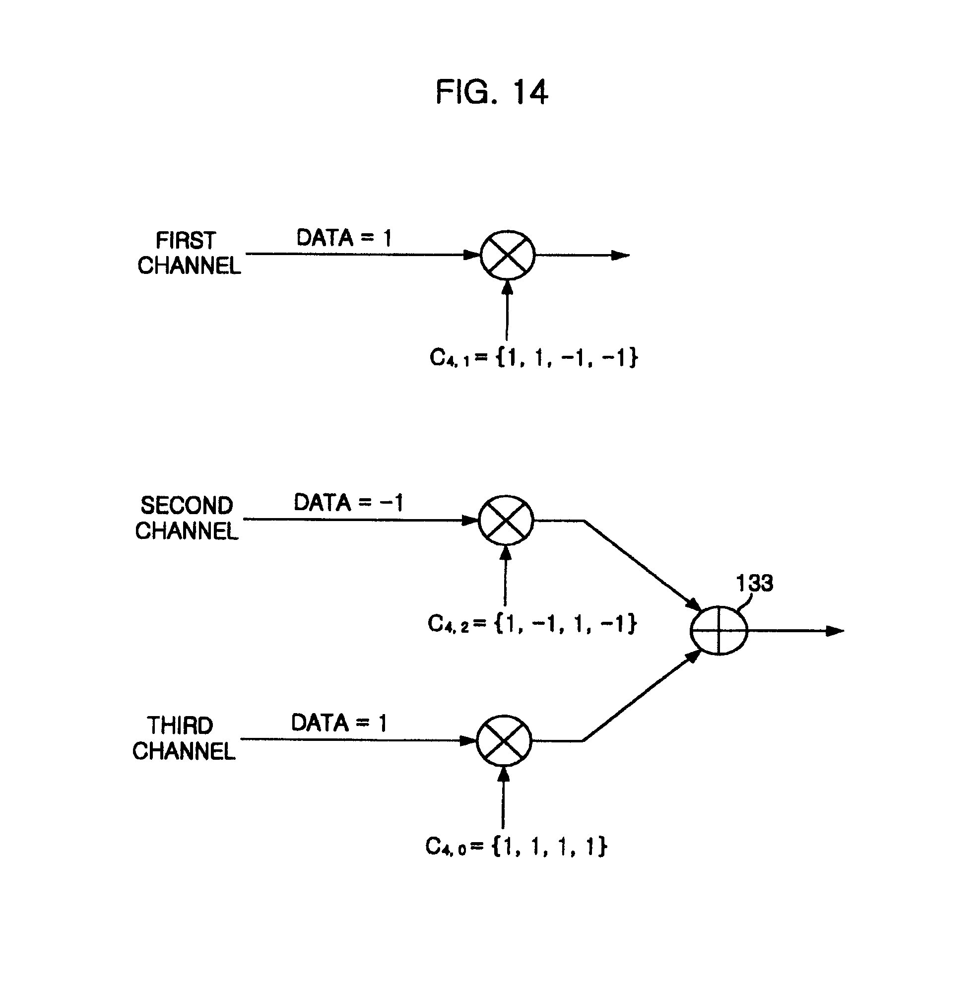
D00015

D00016
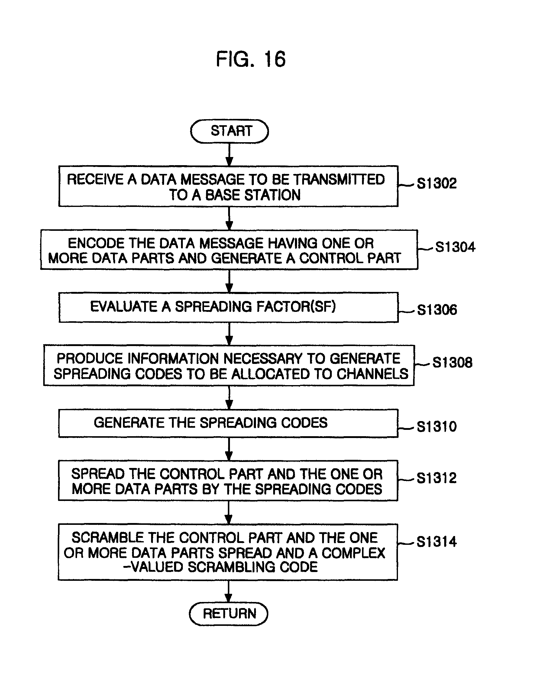
D00017

D00018

D00019

D00020

D00021
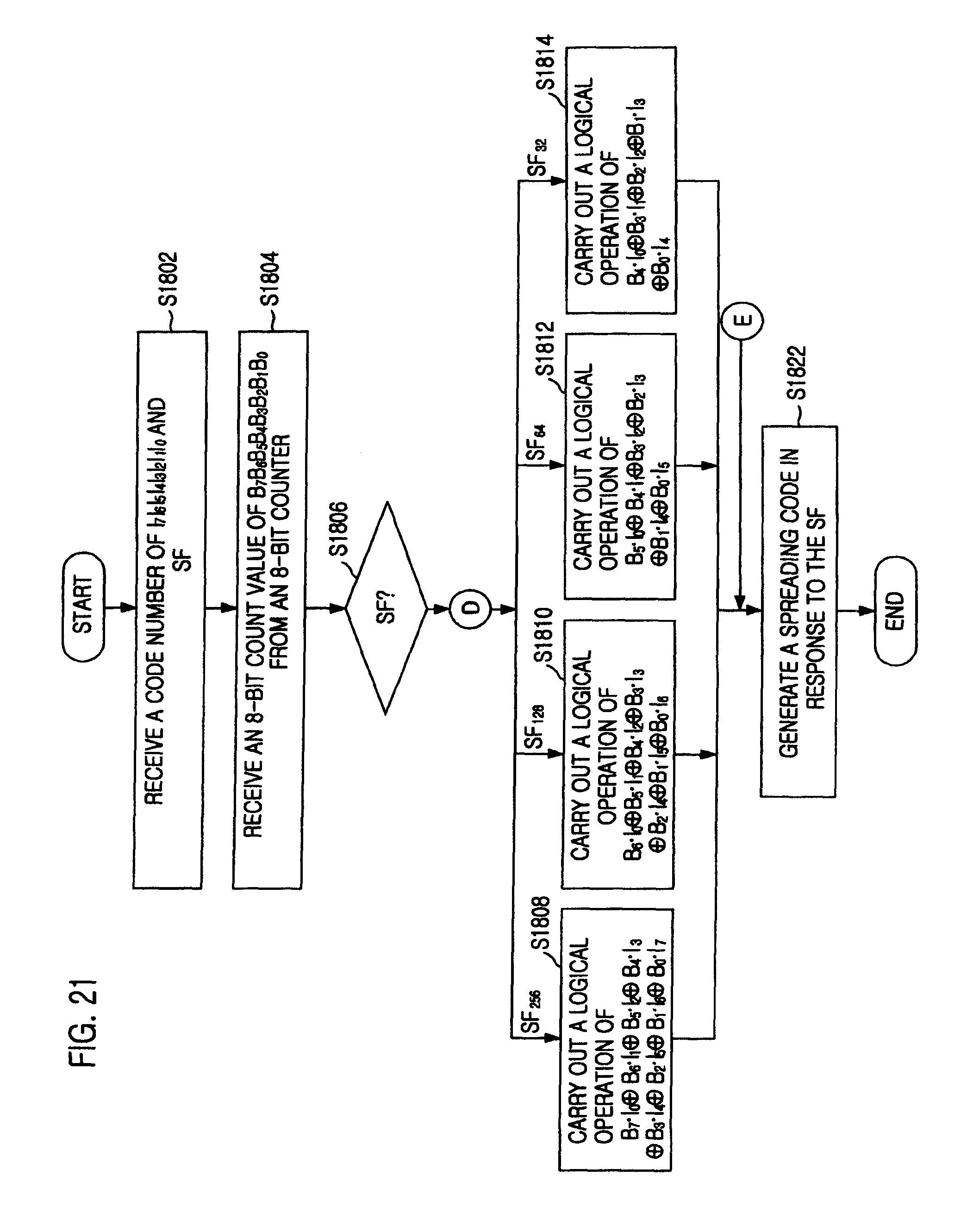
D00022

M00001

M00002

M00003

M00004

M00005

M00006

M00007

M00008

XML
uspto.report is an independent third-party trademark research tool that is not affiliated, endorsed, or sponsored by the United States Patent and Trademark Office (USPTO) or any other governmental organization. The information provided by uspto.report is based on publicly available data at the time of writing and is intended for informational purposes only.
While we strive to provide accurate and up-to-date information, we do not guarantee the accuracy, completeness, reliability, or suitability of the information displayed on this site. The use of this site is at your own risk. Any reliance you place on such information is therefore strictly at your own risk.
All official trademark data, including owner information, should be verified by visiting the official USPTO website at www.uspto.gov. This site is not intended to replace professional legal advice and should not be used as a substitute for consulting with a legal professional who is knowledgeable about trademark law.