Multidimensional rotary motion apparatus moving a reflective surface and method of operating same
Reddy , et al.
U.S. patent number 10,302,935 [Application Number 15/992,003] was granted by the patent office on 2019-05-28 for multidimensional rotary motion apparatus moving a reflective surface and method of operating same. This patent grant is currently assigned to Pentair Water Pool and Spa, Inc.. The grantee listed for this patent is Pentair Water Pool and Spa, Inc.. Invention is credited to Kevin Doyle, Bruce Johnson, Gabriel Perez, Rakesh Reddy.


View All Diagrams
| United States Patent | 10,302,935 |
| Reddy , et al. | May 28, 2019 |
Multidimensional rotary motion apparatus moving a reflective surface and method of operating same
Abstract
A motion control system for controlling an image projected from an underwater projection system in a water feature includes a chassis, a mirror support coupled to the chassis, a mirror member on the mirror support, a first drive member, and a second drive member. The mirror member is configured to reflect the image projected from the underwater projection system in the water feature. The first drive member is coupled to the chassis and configured to rotate the mirror support relative to the chassis about a first axis to move the reflected image in the water feature. The second drive member is coupled to the chassis and a fixed mount and is configured to rotate the chassis and the mirror support about a second axis to move the reflected image in the water feature.
| Inventors: | Reddy; Rakesh (Deerfield Beach, FL), Johnson; Bruce (Deerfield Beach, FL), Doyle; Kevin (Deerfield Beach, FL), Perez; Gabriel (Deerfield Beach, FL) | ||||||||||
|---|---|---|---|---|---|---|---|---|---|---|---|
| Applicant: |
|
||||||||||
| Assignee: | Pentair Water Pool and Spa,
Inc. (Cary, NC) |
||||||||||
| Family ID: | 50028547 | ||||||||||
| Appl. No.: | 15/992,003 | ||||||||||
| Filed: | May 29, 2018 |
Prior Publication Data
| Document Identifier | Publication Date | |
|---|---|---|
| US 20180275395 A1 | Sep 27, 2018 | |
Related U.S. Patent Documents
| Application Number | Filing Date | Patent Number | Issue Date | ||
|---|---|---|---|---|---|
| 15244997 | Aug 23, 2016 | 9983400 | |||
| 13957418 | Sep 6, 2016 | 9435997 | |||
| 13626871 | Aug 23, 2016 | 9423608 | |||
| 61678622 | Aug 1, 2012 | ||||
| Current U.S. Class: | 1/1 |
| Current CPC Class: | E04H 4/148 (20130101); F16H 21/54 (20130101); G02B 26/0816 (20130101); F16H 21/02 (20130101); G02B 26/101 (20130101); G02B 7/1821 (20130101); G05G 11/00 (20130101); G03B 29/00 (20130101) |
| Current International Class: | G02B 26/08 (20060101); G02B 26/10 (20060101); G02B 7/182 (20060101); G05G 11/00 (20060101); F16H 21/02 (20060101); E04H 4/14 (20060101); F16H 21/54 (20060101); G03B 29/00 (20060101) |
References Cited [Referenced By]
U.S. Patent Documents
| 1982639 | December 1934 | Christofferson |
| 2016991 | October 1935 | Dollinger |
| 2500123 | March 1950 | Gwaltney et al. |
| 2808899 | October 1957 | Hofstetter |
| 3262321 | July 1966 | Moul, Jr. |
| 3276191 | October 1966 | Revell |
| 3321345 | May 1967 | Duncan |
| 3337285 | August 1967 | Travis |
| 3337898 | August 1967 | Schmid et al. |
| 3408795 | November 1968 | Revell et al. |
| 3596442 | August 1971 | Neumann |
| 3695008 | October 1972 | Neumann |
| 3774373 | November 1973 | Welch et al. |
| 3985528 | October 1976 | Revell |
| 4054521 | October 1977 | Winzen |
| 4158483 | June 1979 | Fisher et al. |
| 4196461 | April 1980 | Geary |
| 4221576 | September 1980 | Phillips, Jr. |
| 4394146 | July 1983 | Klein |
| 4405342 | September 1983 | Bergman |
| 4470833 | September 1984 | Wolfe |
| 4887197 | December 1989 | Effinger |
| 4905326 | March 1990 | Nakamura et al. |
| 5098767 | March 1992 | Linnersten |
| 5217513 | June 1993 | Armbruster |
| 5271106 | December 1993 | McClish et al. |
| 5405434 | April 1995 | Inculet |
| 5560835 | October 1996 | Williams |
| 5576901 | November 1996 | Hanchett |
| 5846135 | December 1998 | Hoskins et al. |
| 5906752 | May 1999 | Williams |
| 5912423 | June 1999 | Doughty et al. |
| 5934796 | August 1999 | Quereau |
| 6086215 | July 2000 | Giattino et al. |
| 6115511 | September 2000 | Sakai et al. |
| 6152998 | November 2000 | Taylor |
| 6168646 | January 2001 | Craig et al. |
| 6278373 | August 2001 | Jaurigue et al. |
| 6292171 | September 2001 | Fu et al. |
| 6402822 | June 2002 | Najm |
| 6454834 | September 2002 | Livingstone et al. |
| 6472990 | October 2002 | Delmar |
| 6491735 | December 2002 | Najm |
| 6561658 | May 2003 | Mochizuki |
| 6592228 | July 2003 | Kawashima et al. |
| 6596059 | July 2003 | Greist et al. |
| 6632269 | October 2003 | Najm |
| 6743282 | June 2004 | Najm |
| 6781329 | August 2004 | Mueller et al. |
| 6827464 | December 2004 | Koren et al. |
| 6843834 | January 2005 | Schumacher |
| 6857746 | February 2005 | Dyner |
| 6906686 | June 2005 | Ishikawa |
| 6936978 | August 2005 | Morgan et al. |
| 6951411 | October 2005 | Kumar et al. |
| 6956696 | October 2005 | Hachkowski et al. |
| 7142168 | November 2006 | Sinclair |
| 7151264 | December 2006 | Ehlers, Sr. |
| 7161311 | January 2007 | Mueller et al. |
| 7186290 | March 2007 | Sheehan et al. |
| 7187141 | March 2007 | Mueller et al. |
| 7244294 | July 2007 | Kates |
| 7274382 | September 2007 | Plut |
| 7292252 | November 2007 | Matsuda |
| 7303301 | December 2007 | Koren et al. |
| 7357525 | April 2008 | Doyle |
| 7410268 | August 2008 | Koren et al. |
| 7413319 | August 2008 | Longoria et al. |
| 7471432 | December 2008 | Pruyn |
| 7482764 | January 2009 | Morgan et al. |
| 7524069 | April 2009 | Murayama et al. |
| 7534057 | May 2009 | Jones et al. |
| 7699515 | April 2010 | Faber et al. |
| 7712913 | May 2010 | Gardenier et al. |
| 7717582 | May 2010 | Longoria et al. |
| 7735385 | June 2010 | Wilson et al. |
| 7740367 | June 2010 | Koren |
| 7744237 | June 2010 | Potucek et al. |
| 7810942 | October 2010 | Kunkel et al. |
| 7862179 | January 2011 | Shan et al. |
| 7896940 | March 2011 | Sundet et al. |
| 7982935 | July 2011 | Grapov et al. |
| 8047475 | November 2011 | Fukumoto et al. |
| 8057112 | November 2011 | Amadril et al. |
| 8118434 | February 2012 | Turner et al. |
| 8179586 | May 2012 | Schofield et al. |
| 8313567 | November 2012 | Sullivan |
| 8801191 | August 2014 | Nemeth et al. |
| 9423608 | August 2016 | Doyle |
| 9435997 | September 2016 | Reddy |
| 9983400 | May 2018 | Reddy |
| 2003/0230061 | December 2003 | Kubokawa et al. |
| 2005/0035728 | February 2005 | Schanberger et al. |
| 2005/0047134 | March 2005 | Mueller et al. |
| 2005/0146777 | July 2005 | Russell |
| 2005/0150382 | July 2005 | Sheehan et al. |
| 2006/0070527 | April 2006 | Chapman et al. |
| 2006/0102006 | May 2006 | Powell |
| 2007/0035862 | February 2007 | Brouwer et al. |
| 2007/0229929 | October 2007 | Soreide et al. |
| 2007/0257181 | November 2007 | Dittmer et al. |
| 2008/0068493 | March 2008 | Hida et al. |
| 2008/0072763 | March 2008 | Hauville |
| 2009/0061761 | March 2009 | Yang et al. |
| 2009/0121657 | May 2009 | Erchak et al. |
| 2009/0174868 | July 2009 | Matsuda |
| 2010/0019686 | January 2010 | Gutierrez, Jr. |
| 2010/0031767 | February 2010 | Chenu |
| 2010/0057803 | March 2010 | Ellis et al. |
| 2010/0128122 | May 2010 | Wright et al. |
| 2010/0250449 | September 2010 | Doyle et al. |
| 2010/0302515 | December 2010 | Plut |
| 2010/0331857 | December 2010 | Doyle et al. |
| 2011/0061527 | March 2011 | Sullivan |
| 2011/0146440 | June 2011 | Feng |
| 2011/0163677 | July 2011 | Baret et al. |
| 2011/0246509 | October 2011 | Migita et al. |
| 2011/0297655 | December 2011 | Ueda |
| 2012/0035469 | February 2012 | Whelan et al. |
| 2012/0133911 | May 2012 | LaDuke |
| 2013/0215012 | August 2013 | Reddy et al. |
| 2013/0215394 | August 2013 | Reddy et al. |
| 2013/0308064 | November 2013 | LaDuke |
| 2014/0078409 | March 2014 | Wang |
| 2014/0210373 | July 2014 | Baret |
| 2007216901 | Oct 2007 | AU | |||
| 201180381 | Jan 2009 | CN | |||
| 19654844 | Jul 1998 | DE | |||
| 102009059689 | Jun 2011 | DE | |||
| 0838696 | Apr 1998 | EP | |||
| 1376509 | Jan 2004 | EP | |||
| 2863345 | Oct 2005 | FR | |||
| H0679194 | Mar 1994 | JP | |||
| H06233945 | Aug 1994 | JP | |||
| H06246120 | Sep 1994 | JP | |||
| H07275626 | Oct 1995 | JP | |||
| H0921245 | Jan 1997 | JP | |||
| H11104416 | Apr 1999 | JP | |||
| 2008216412 | Sep 2008 | JP | |||
| 9705595 | Feb 1997 | WO | |||
| 9931560 | Jun 1999 | WO | |||
| 0204091 | Jan 2002 | WO | |||
| 2009008710 | Jan 2009 | WO | |||
| 2009156602 | Dec 2009 | WO | |||
| 2010043956 | Apr 2010 | WO | |||
| 2012136907 | Oct 2012 | WO | |||
| 2014043135 | Mar 2014 | WO | |||
| 2014043139 | Mar 2014 | WO | |||
Other References
|
ILDA; International Laser Display Association; New products and services from ILDA Members; Copyright 2004-2012 International Laser Display Association; retrieved from U.S Patent Office; U.S. Pat. No. 9,983,400; 9 pages. cited by applicant . Gilje, HC; "Conversations with spaces"; Feb. 15, 2009 (http://hcgilje.wordpress.com/tag/projection/); retrieved from U.S. Patent Office; U.S. Pat. No. 9,983,400; 13 pages. cited by applicant . FLIR; Pan-Tilt Unit-D46 Models; Copyright 1999-2013 FLIR Systems, Inc.; retrieved from U.S Patent Office; U.S. Pat. No. 9,983,400; 1 page. cited by applicant . Directed Perception; PTU-D46: Quick Configuration Guide; Jan. 2009; retrieved from U.S Patent Office; U.S. Pat. No. 3,983,400; 6 pages. cited by applicant . Nitish Swarup; Design and Control of a Two-Axis Gimbal System for use in Active Vision; Massachusetts Institute of Technology; May 1993; retrieved from U.S. Patent Office; U.S. Pat. No. 9,983,400; 44 pages. cited by applicant . OptimAir; Installation & Operation Manual; Dec. 2006; retrieved from U.S. Patent Office; U.S. Pat. No. 9,983,400; 20 pages. cited by applicant . Aubin John, F. and Keenan, Vincent B.; A Low Profile Three Axis Gimbal Assembly for Radome Measurements; ORBIT/FR, Inc.; retrieved from U.S. Patent Office; U.S. Pat. No. 9,983,400; 5 pages. cited by applicant . International Search Report for PCT/GB2013/050388; dated May 17, 2013; 5 pages. cited by applicant . International Search Report for PCT/US13/53084; dated Dec. 6, 2013; 4 pages. cited by applicant . International Search Report for PCT/US13/53315; dated Jan. 3, 2014; 2 pages. cited by applicant. |
Primary Examiner: Carruth; Jennifer D.
Attorney, Agent or Firm: Quarles & Brady LLP
Parent Case Text
CROSS REFERENCE TO RELATED APPLICATIONS
This application is a continuation of U.S. patent application Ser. No. 15/244,997 filed Aug. 23, 2016, which is a continuation of U.S. patent application Ser. No. 13/957,418 filed Aug. 1, 2013, which is a continuation-in-part of U.S. patent application Ser. No. 13/626,871 filed Sep. 25, 2012, and also claims the priority of U.S. Provisional Patent Application No. 61/678,622, filed Aug. 1, 2012, all of which are incorporated herein by reference.
Claims
The invention claimed is:
1. A motion control system for controlling an image projected from an underwater projection system in a water feature, the motion control system comprising: a chassis; a mirror support coupled to the chassis; a mirror member on the mirror support, the mirror member configured to reflect the image projected from the underwater projection system in the water feature; a first drive member coupled to the chassis and configured to rotate the mirror support relative to the chassis about a first axis to move the reflected image in the water feature; and a second drive member coupled to the chassis and a fixed mount, the second drive member configured to rotate the chassis and the mirror support about a second axis to move the reflected image in the water feature.
2. The motion control system of claim 1, wherein the first axis and the second axis are orthogonal to each other.
3. The motion control system of claim 1, wherein the first drive member is configured to rotate the mirror support in a vertical direction.
4. The motion control system of claim 1, wherein the second drive member is configured to rotate the mirror support in a horizontal direction.
5. The motion control system of claim 1 and further comprising a first rotating cam coupled to the first drive member and a first linkage coupled to the first rotating cam and the mirror support.
6. The motion control system of claim 5, wherein the mirror support is coupled to the chassis by a hinge, and the first drive member is configured to rotate the first rotating cam, which moves the first linkage to rotate the mirror support about the hinge.
7. The motion control system of claim 1 and further comprising second rotating cam coupled to the second drive member and a second linkage coupled to the rotating cam and the fixed mount.
8. The motion control system of claim 7, wherein the chassis is coupled to a pivot pin aligned with the second axis, and the second drive member is configured to rotate the second rotating cam, which moves the second linkage relative to the fixed mount to rotate the chassis about the second axis.
9. The motion control system of claim 1 and further comprising a controller configured to control rotation of the mirror support about the first axis and the second axis.
10. The motion control system of claim 9 and further comprising a sensor in communication with the controller and configured to provide feedback related to a position of the mirror support relative to one of the first axis and the second axis.
11. The motion control system of claim 10, wherein the controller is configured to control rotation of the mirror support about the first axis and the second axis based on the feedback from the sensor.
12. The motion control system of claim 10, wherein the sensor includes a vertical motion sensor and a horizontal motion sensor.
13. The motion control system of claim 1, wherein the first drive member and the second drive member are each coupled to the chassis at stationary positions relative to the chassis.
14. The motion control system of claim 1, wherein the first drive member and the second drive member are one of motors, magnetic drives, piezo drives, and mechanical drives.
15. The motion control system of claim 1, wherein the water feature is a pool.
16. An underwater projection system for a water feature, the underwater projection system comprising: a projector configured to project an image; a motion control system configured to reflect the image from the projector within the water feature, the motion control system including a chassis, a mirror support coupled to the chassis, a mirror member disposed on the mirror support, a first drive member configured to rotate the mirror support relative to the chassis about a first axis to move the reflected image within the water feature, and a second drive member configured to rotate the chassis and the mirror support about a second axis to move the reflected image within the water feature; and a controller configured to control rotation of the mirror support about the first axis and the second axis.
17. The underwater projection system of claim 16, wherein the controller is further configured to control the projector.
18. The underwater projection system of claim 16, wherein the first drive member and the second drive member are one of motors, magnetic drives, piezo drives, and mechanical drives.
19. The underwater projection system of claim 16 and further comprising a sensor in communication with the controller and configured to provide feedback related to a position of the mirror support relative to one of the first axis and the second axis, wherein the controller is configured to control rotation of the mirror support about the first axis and the second axis based on the feedback from the sensor.
20. The underwater projection system of claim 16, wherein the first drive member and the second drive member are each coupled to the chassis at stationary positions relative to the chassis.
Description
BACKGROUND
In applications having light projection, one technique to allow mechanical motion to direct the light in the x and y axis is to use two discrete mirrors with one mirror allowing for rotation of the image in the x axis which is further superimposed on another mirror allowing for further rotation in the y axis. An advantage of this system is simplicity--the two axes can be parked on a rotating shaft such as a motor or a galvanometer with a simple control mechanism to control the position of the mirrors. A principal problem with this type of control system is that the reflection occurs on two surfaces resulting in losses and inaccuracies from the mirror surfaces imperfections. These issues result in a reduction of image intensity and quality. The two mirror configuration also requires a larger size/footprint. The primary mirror may be small but the secondary mirror, which collects all the diverging light from the primary source will need to be larger.
In addition, various methods exist for tip and tilting, x and y translation, of a single reflective surface. Some of them are used in sensitive applications such as in the aviation, space and medical fields and are very accurate, sometimes down to the milliradian. They use forces such as magnetic, mechanical, piezo, and other means of locomotion to tilt a system that is held in either a gimbal or a ball joint. Such systems need complex and carefully manufactured electronics to close a feedback loop allowing for proper functioning of the system rendering and tilt systems with a single reflective surface has a limited range of motion despite the higher resolution and cost, further limiting their applicability to most general applications. Alternately, other existing techniques that have a single reflective surface and employ a mechanical system need articulated arms and carefully designed ball joints to function, similarly saddling them with higher manufacturing costs and requiring larger footprints for deployment.
Another technique of enabling a single reflective surface in more than one axis of rotation employs a primary rotation medium that is coupled to a secondary rotation medium which in turn rotates the mirror. These devices actually move the second motor and as a result need more space for operation, again increasing the footprint of the system. The addition of a moving second motor adds mass to the moving components and increases inertia. The inertia of the motor can prohibit a smaller, lower power first motor from being used or from a small first motor to move with higher acceleration and deceleration. This higher inertia also renders such systems more prone to errors due to the larger moving masses. Further because the mirror is far from the main axis of rotation, the mirror surface has to be larger, making it impractical for limited physical space applications. These factors contribute to making these systems less accurate and requiring more space in a footprint for deployment in any control system.
Thus, there exists a need for a device and a method that provides tip and tilt control on two axis, offers the ability for systems to calculate the relative or absolute position of the mount surface or element quickly and efficiently, provide for fixed motors which in turn lower motor torque and provide a lower inertia of moving components and be cost effective. The system also needs to provide the motion at high speed, have a small form factor /net volume, use smaller motors to save weight, reduce cost, reduce inertial interference, lower power consumption, and result in robust, compact, cost effective device with high accuracy for mechanical and electrical systems.
SUMMARY
Some embodiments provide a motion control system for controlling an image projected from an underwater projection system in a water feature. The motion control system includes a chassis, a mirror support coupled to the chassis, a mirror member on the mirror support, a first drive member, and a second drive member. The mirror member is configured to reflect the image projected from the underwater projection system in the water feature. The first drive member is coupled to the chassis and configured to rotate the mirror support relative to the chassis about a first axis to move the reflected image in the water feature. The second drive member is coupled to the chassis and a fixed mount and is configured to rotate the chassis and the mirror support about a second axis to move the reflected image in the water feature.
Some embodiments provide an underwater projection system for a water feature. The underwater projection system includes a projector configured to project an image, a motion control system configured to reflect the image from the projector within the water feature, and a controller. The motion control system includes a chassis, a mirror support coupled to the chassis, and a mirror member disposed on the mirror support. The motion control system also includes a first drive member configured to rotate the mirror support relative to the chassis about a first axis to move the reflected image within the water feature, and a second drive member configured to rotate the chassis and the mirror support about a second axis to move the reflected image within the water feature. The controller is configured to control rotation of the mirror support about the first axis and the second axis.
Moreover, the above objects and advantages of the invention are illustrative, and not exhaustive, of those which can be achieved by the invention. Thus, these and other objects and advantages of the invention will be apparent from the description herein, both as embodied herein and as modified in view of any variations which will be apparent to those skilled in the art.
BRIEF DESCRIPTION OF THE DRAWINGS
Embodiments of the invention are explained in greater detail by way of the drawings, where the same reference numerals refer to the same features.
FIG. 1 shows an isometric view of the rotary motion system and driver;
FIG. 2 shows a further isometric view of the rotary motion control system and drive of FIG. 1;
FIG. 3 shows an isometric view of the second drive shaft of the exemplary embodiment of FIG. 2;
FIG. 4 shows an isometric view of the first drive shaft coupled to the support shaft of FIG. 2;
FIG. 5 provides a further isometric view of the first drive shaft coupled to the mirror support of FIG. 4 with relative motion indicated;
FIG. 6 shows a plan view for a controller for the exemplary embodiment of FIG. 1;
FIGS. 7A-7D show various shapes and configurations of mirrors and optics that may also be used in conjunction with the exemplary embodiments of the invention;
FIGS. 8A-8C show isometric left, right, and bottom views of a further exemplary embodiment of the rotary motion control system;
FIG. 9 shows an isometric view of the chassis of the exemplary embodiment of FIGS. 8A-C; and
FIGS. 10A and 10B show the pivot member of the exemplary embodiment of FIGS. 8A-C with the support member.
DETAILED DESCRIPTION OF THE INVENTION
FIG. 1 shows an isometric view of the rotary motion control system and driver. The system includes a mounting element 310 coupled to and output or support shaft 320 through a two-axis coupling generally shown as 400, 500 having at least two input shafts 420, 520 which are in turn coupled to at least two drive mechanisms 110,120, respectively. In this exemplary embodiment shown, the at least two drive mechanisms 110, 120 are shown as electromagnetic drive mechanisms 110, 120. These can be mechanically, magnetically or electromechanically coupled to the at least two input shafts 420, 520 as best shown in FIG. 2. The two electromagnetic drive mechanisms 110, 120 are coupled to a chassis 200. The chassis serves to hold the motors stationary at a required position and angle. The angle in the embodiment is 90 degrees but other angles could also be employed without departing from the spirit of the invention. In FIG. 1, drive mechanisms 110 and 120 represent an electric motor. Some non-limiting examples of further mechanical driving systems include but are certainly not limited to galvanometers, stepper motors, motors with gears or transmissions, and the like. Modifications can be made to the driving source without departing from the spirit of the invention.
FIG. 2 shows a further isometric view of the rotator motion control system and drive of FIG. 1. In this figure, the drive mechanisms 110, 120 have been omitted to more clearly see the workings of the embodiment. FIG. 2 provides a clearer view of the two-axis coupling members 400, 500. As shown in FIG. 2, at least two indexing blades 430, 530 are provided to index the at least two input shafts 420, 520, here shown as a first input shaft 520 and a second input shaft 420, which are driven from drive shafts 410, 510 coupled to the input shafts 420, 520 and drive members. The drive members may be electrical motors, magnetic drives, piezo drives, mechanical drives, or similar devices, as noted above.
The drive mechanisms 110, 120 move drive shafts 410 and 510 which impart movement in the input shafts 420, 520, respectively. The drive shafts 410, 510 allow rotary torque from drive mechanisms 110, 120 to be transmitted to the coupling members 400, 500. The coupling is created in this exemplary embodiment through keying the drive shafts 410, 510 within the input shafts 420,520. In further exemplary embodiments the drive and input shafts may be a single component. These points of coupling in the exemplary embodiment of FIG. 2 are keyed to prevent slippage between the drive shaft 410,510 and input shaft 420,520. The coupling of the drive shafts 410,510 may allow for a screw or other fastening device to be used that allows for parts to be connected to them. Each blade is coupled to the controller through optical sensors 440, 540 which, in conjunction with a controller 700 index the position of the at least two indexing blades 430,530 and thereby the position of the input shafts 420, 520.
In the exemplary embodiment shown, the sensors are, as a non-limiting example, opto-interrupter type sensors. In further exemplary embodiments, other sensors can be used, for instance but certainly not limited to, Hall Effect sensors, potentiometers, capacitive sensors, and the like. The sensor type shown in the exemplary embodiment allows for the edges of the indexing blades 430, 530 to be detected which in turn allows for detection of an absolute position for the arms. Alternately, in one of the further exemplary embodiments for instance, one can use Hall Effect sensors, capacitive sensors or potentiometers to provide a linear or multi-point signal to identify the position directly. In further exemplary embodiments, one can couple the sensors to a different part of the drive mechanism, such as the other side of the motor, or to any part of the gearbox, that can allow a controller to track the relative motion and relate this to the pitch and yaw translation of the reflected image or radiation without departing from the spirit of the invention.
The first coupling member 500 is linked to an at least one support shaft 320 and the second input shaft 520 guides the support shaft 320 in an at least one channel member 445 to facilitate controlled motion of the mounting element 310. The motion of input shafts 420, 520 are transferred through the linkage 545 or the channel member 445 which in turn propel and guide the at least one support shaft 320. The at least one support shaft 320 passes through the channel 450 and is coupled to the coupling member 500 by an at least one input coupling or linkage 545 which is coupled to and drives the at least one support shaft 320. Although a single support shaft 320, a single channeled member 445, and a single drive or input coupling 545 are provided, additional elements or members may be utilized without departing from the spirit of the invention. In the exemplary embodiment shown, the at least one input coupling 545 fits within a curved portion of the at least one channeled member 445, the at least one support drive or input coupling 545. The at least one support shaft 320 supports an at least one mount element or base 310. The exemplary embodiment shows a mirror coupled to the at least one mount element or base 310 and the mount element or base 310 being directly secured to the driven support shaft 320. However, several different techniques to attach the at least one mount element or base 310 to the support shaft 320, for instance variations can be provided to aid in the manufacturability and durability of the product. Some non-limiting examples of alternate mechanisms for coupling the driven shaft can include designing the mirror to be inserted into a socket or cavity to ensure accurate positioning of the mirror without departing from the spirit of the invention. The surface that is moved by the driven shaft may also be secured to the shaft using a screw or other fastening mechanism or similar mechanisms. The exemplary embodiment shown uses a flat mirror, however, several different shapes of mirrors and optics are contemplated, as further seen in FIGS. 7A through 7D and described herein below.
The at least two drive mechanisms 110, 120 input motion through an at least two drive shafts or couplings 410, 510 which in turn move the at least two input shafts 420, 520 respectively. The at least two input shafts 420, 520 turn and input or indexing blades 430, 530 measures the degree of this movement and with the controller 700 control this movement. The at least two input shafts 420, 520 are coupled to one another and the at least one support shaft 320 through input coupling 545 which extends from input shaft 520 and is coupled through the input coupling 545 to the support shaft or member 320 and the channel 450 in input shaft 420 through which the support shaft 320 passes. In this fashion the rotation of the drive shafts 410, 510 is translated into motion of the respective at least two input shafts 420, 520. This motion in turn moves input shaft 520 and support shaft or member 320 about the axis of pin 600 which guides support member or shaft 320 within the channel 450. By sliding within channel 450 and about the hinge created by pin 600 the pitch and yaw of support shaft 320 is achieved.
The sliding and motion of the two axis coupling can be further aided by adding lubrication to the moving parts and the channel. The lubricant may be of any typical type, including but not limited to an oil, silicone, mineral, or similar lubricant which can be applied or contained in a bath to adhere to the moving parts of the coupling members 400, 500 of the two axis coupling to allow for free and smooth low friction motion. Additionally, the fabrication of members 300, 400, and 500 may include low friction wear surfaces which come in contact with other moving members using low friction materials such as a high performance polymer, such as but certainly not limited to Polyoxymethylene (POM), Polyetheretherketone (PEEK), Polyimide (PI), Polyamide (PA), Ultra High Molecular Weight Polyethylene (UHMWPE) or Polyethylene Terephthalate (PET) as non-limiting examples. These materials can be used to fabricate the entirety of the component or the wear surfaces. The components in the exemplary embodiment are as a nonlimiting example fabricated completely from POM. Additional embodiments can utilize a metal, such as but certainly not limited to anodized aluminum, stainless steel, or a composite material such as a reinforced graphite or high performance polymer impregnated with a composite material, or similar compounds in the fabrication of the device to minimize wear and friction.
FIG. 3 shows an isometric view of the second input shaft of the exemplary embodiment of FIG. 2. As shown in the figure, an indexing blade 430 is shown with an input shaft 420 coupled thereto. A curved section 441 of the channeled member 445 is provided and the channel 450 in the channel member 445 is shown therein. The channel 450 is created so that the at least one support shaft or member 320 can glide through it when propelled by the second input shaft 420. However it is the second indexing blade 430 that controls the position of the at least one mount element 310 in the secondary axis.
FIG. 4 shows an isometric view of the first input shaft coupled to the mirror support of FIG. 2. As shown first support shaft 520 is coupled to the mirror support 320 through input coupling 545. A central drive shaft 510 is located within the first support shaft 520. As shown, this is a joint coupling with a pin member 600, the joint coupling permitting two-axis motion of the mirror base 310 through the mirror support 320, as better descried in FIG. 5. The second support member 420 restrains and guides the motion imparted by the first support member 520 allows for pan-yaw motion of the at least one mirror base 310. The pin 600 may also be but is certainly not limited to a screw, a rivet, a standoff bolt or the like. The design of the hinge member or input coupling 545 may allow a screw to secure drive shaft 510 to input shaft 520, permitting only one axis of motion. Various approaches may be used to serve the function of pin 600 without departing from the spirit of the invention.
FIG. 5 provides a further isometric view of the first input shaft coupled to the mirror support of FIG. 4 with relative motion indicated. FIG. 5 highlights the two axis of motion available to the first input shaft 520. A driven motion turns the input shaft 520, as shown by the arrow, in a direction based on motion imparted on the index blade 530. This can be imparted electromagnetically, as would be provided by a galvanometer or electromagnetic motor or the like, or through mechanical means, such as but not limited to a stepper motor or worm gear motor or the like. The relative motion of the blade 530 is translated very accurately to motion in the input shaft 520. The input shaft in turn turns as indicated. In addition, through the pinned joint of input coupling 545, mirror support shaft 320 is free to pivot about the pin 600 in the input coupling 545. This axis of motion is restrained by the channel 450 of the first input shaft and its channel member 445. As noted above, in this fashion the motion of the mirror support 310 is accomplished and controlled.
FIG. 6 shows a plan view for a controller for the exemplary embodiment of FIG. 1. The controller 700 is coupled to or contains a Rotary Motion Control System and Driver Circuit. It provides a module for calibration 750 of the system and a separate module for pan and yaw correction 760, as shown. The circuit includes sensors 440, in this case opto-isolator sensors as discussed further herein below, 440, 540 as seen in FIG. 2 in the system providing position feedback for the first axis of motion (Axis A) and second axis of motion (Axis B) relative to the at least two drive mechanism alone or in conjunction with the indexing blades. Relative positions of the at least two indexing blades 430, 530 are related to the position of the system in the calibration module. The pan and yaw correction module takes programmed corrections provided during or after operations and translates this to relative X axis and Y axis outputs 730, 740 respectively.
One non-limiting example of an application of the exemplary embodiment of the instant invention as shown and described herein is as the rotary motion control system and driver circuit as a component of an underwater projection system secondary steering mechanism used in conjunction with an underwater DLP projection system. The second mirror functions to move reflected images from the underwater DLP projection system within a defined boundary space within a water feature such as, but not limited, to a pool as described in Applicant's co-pending U.S. patent application Ser. No., 13/533,966, filed Jun. 26, 2012. The controller 700 may be a controller for such an underwater projection system or a further controller or a separate controller communicating with the controller 700 and the modules discussed above.
FIGS. 7A-7D show various shapes of mirror elements that may alternatively be used in conjunction with the exemplary embodiment of FIG. 1. In addition to the flat mirror base 310 shown in FIGS. 1-6, FIGS. 7A-7D show various shapes and configurations of mirrors and optics that may also be used in conjunction with the exemplary embodiment. These embodiments are non-limiting examples and are provided to show the breadth of the utility of the invention as a beam steering device. FIG. 7A represents a multifaceted mirror or optic 360, having several reflective planes and coupled to a shortened mirror support 320 and coupling 330 that receives the pin 600 as identified above. FIG. 7B shows a divergent mirror 350 with a generally convex shape similar to a surface portion of a sphere coupled to the mirror support 320 and the coupling 330. FIG. 7C shows a flat mirror element 310 with an angled attachment point 770 at the attachment point of the mirror support 320 and coupling 330. FIG. 7D shows an offset attachment point for a flat mirror base 310 with mirror support 320 not attaching at the center of the mirror base 310 but at an offset point and having the mirror support 320 extend from there to the coupling 330. In addition, the support shaft 320 and mount element 310 can attach other elements such as optics, optical modulations, diffraction gratings, reflective surfaces and the like.
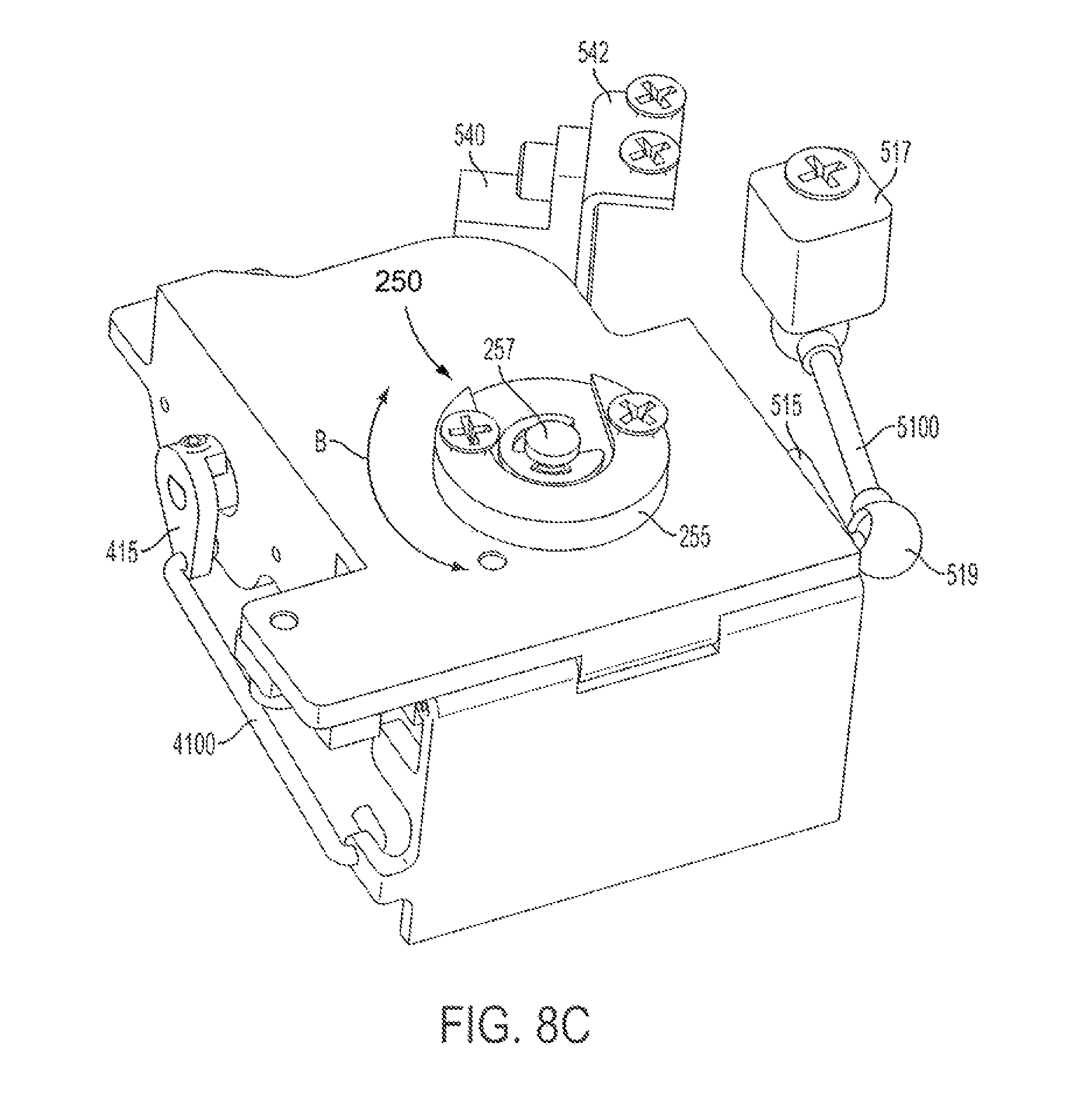
FIGS. 8A-8C show isometric left, isometric right, and isometric bottom views of a further exemplary embodiment of the rotary motion control system. The system moves a mirror member 310 on a mirror support 320. A chassis or body member 200 has an at least one motor, shown as a first motor 110 for imparting vertical or up-down motions in the mirror element 310 and a second motor 120 imparting horizontal or side to side motion as described herein below.
As seen in FIG. 8A an at least one vertical cam 415 is coupled to the first or vertical drive motor 110. The cam 415 is coupled to an attachment point 312 that extends from the mirror support 320. The attachment point 312 is connected to the vertical cam 415 through a first of an at least two drive shafts or linkages, here vertical linkage 4100. A similar second of an at least two drive shafts or linkages is shown in FIGS. 8A-9 as horizontal linkage 5100. Additional shafts, input shafts, or linkages may be used to couple the respective at least one cams to the mirror element and impart relative motion. The vertical linkage is also in communication with an at least one sensor, here shown as vertical sensor 440 mounted on a sensor support 442. The sensor 440 determines the condition of the movement imparted to the mirror element 310 by the linkage 4100. In this instance the at least one sensor also includes a horizontal movement sensor 540 and a bracket or support member 542 in communication with the horizontal linkage. The horizontal movement as described herein below in relation to FIGS. 8B-10B is also thereby tracked.
The motion produced by the at least one vertical cam 415 through the linkage 4100 provides a moment of movement about a hinge 215 and hinge pin 212, as better seen in relation to FIGS. 8B and 9. The movement is about the axis of the hinge pin 212 and is shown in the figure with the aid of arrows as relative motion A. The hinge 215 acts as a first restraint mechanism permitting the motion indicated.
FIG. 8B shows an isometric view from the side of the device opposite that of 8A. The hinge 215 and hinge pin 212 are more clearly seen in relation to the mirror support 320. The at least one motor, here vertical motor 110 and horizontal motor 120, are also shown. A fixed mount 517 exists apart from the chassis 210. The mount secures a ball and socket joint acting as a coupling to the second of an at least two drive shafts or linkages, here the horizontal linkage 5100. The horizontal linkage 5100 is coupled by a further ball and socket coupling mechanism at an opposite end of the horizontal linkage 5100 to a further at least one cam, here horizontal cam 515. The horizontal cam 515 is coupled to the drive motor 120 and acts to move the chassis 210 about the ends of the horizontal linkage 5100. As noted above, a horizontal sensor 540 and support member or bracket 542 engage a sensor element 432 to determine horizontal movement.
The motion of the horizontal cam 515 moves the coupling with the at least one horizontal linkage 5100. The other end of the linkage being fixed to the fixed mount 517, the motion is restrained and the relative distance between the coupling points fixed. The circular motion of the horizontal cam results in a twisting moment about the chassis 210 relative to FIG. 8B shown in the figures by movement arrow B. This twisting moment is the horizontal movement as the device on a pivot point 257, the fixed coupling acting as a second further restraining mechanism, as further shown and described in relation to FIG. 8C.
FIG. 8C shows a bottom view of the exemplary embodiment of FIGS. 8A-8B. A pivot member 250 is provided passing through an element of the chassis as best seen in FIG. 9. The pivot member 250 includes a pivot member support body 255 and the support body has or acts as a low friction spacer. The pivot member 250 with its pivot pin 257 allows for movement as indicated by movement arrow B, about the axis of the pivot pin 257. This is imparted by the translation of the horizontal cam 515 imparting motion through the couplings to the horizontal linkage 5100. As noted previously a sensor 540 and bracket 542 are provided to sense the horizontal disposition of the device.
FIG. 9 shows a further isometric view of the chassis of the exemplary embodiment of FIGS. 8A-8B. As more clearly seen in this view the hinge 215 and pivot pin member hole 251 are clearly seen. It is about the axis of these two elements the chassis is moved to import both pitch and yaw or vertical and horizontal motion in the mirror element 310. In the case of the up-down or vertical motion provided by the vertical linkage 4100, the hinge 215 and hinge pin or member 212 restrain the devices relative motion. Further, the inset nature of the pivot member prevents unbridled movement and limits the motion imparted to rotation about an axis, namely the axis of the pivot pin 257. As best shown by the arrows showing relative motion.
FIG. 10A and 10B show the pivot member 250 of the exemplary embodiment of FIGS. 8A-C with the pivot member support body 255. The pivot member 250 includes the pivot pin 257. The pivot pin 257 is oriented such that the chassis 210 rests atop of it. It is held by the pivot member support body 255. The pivot member support body 255 passes through the pivot member hole 251. The pivot pin 257 is in contact with the pivot member support body 255. The pivot member support body 255 is provided with a slot 810 which corresponds to a groove 825 on the pivot pin 257. The pivot pin 257 is slidingly coupled to the pivot member support body 255. This is one example of providing the pivot pin 257, further variations in the exact members may be provided such that a pivot pin 257 supports the chassis 210 and allows for the movement indicated.
Thus through the at least one cam, here horizontal and vertical cams, coupled to the mirror support member 320 through an at least two linkages and restrained by a hinge member and a pivot member, the mirror element 310 is provided both vertical or up down movement as well as horizontal or side to side movement in the further embodiment.
The embodiments and examples discussed herein are non-limiting examples. The invention is described in detail with respect to preferred embodiments, and it will now be apparent from the foregoing to those skilled in the art that changes and modifications may be made without departing from the invention in its broader aspects, and the invention, therefore, as defined in the claims is intended to cover all such changes and modifications as fall within the true spirit of the invention.
* * * * *
References
D00000
D00001
D00002
D00003
D00004
D00005
D00006
D00007
D00008
D00009
D00010
D00011
D00012

D00013
D00014

D00015

XML
uspto.report is an independent third-party trademark research tool that is not affiliated, endorsed, or sponsored by the United States Patent and Trademark Office (USPTO) or any other governmental organization. The information provided by uspto.report is based on publicly available data at the time of writing and is intended for informational purposes only.
While we strive to provide accurate and up-to-date information, we do not guarantee the accuracy, completeness, reliability, or suitability of the information displayed on this site. The use of this site is at your own risk. Any reliance you place on such information is therefore strictly at your own risk.
All official trademark data, including owner information, should be verified by visiting the official USPTO website at www.uspto.gov. This site is not intended to replace professional legal advice and should not be used as a substitute for consulting with a legal professional who is knowledgeable about trademark law.