Alignment sleeve assembly and fiber optic adapter
Tong , et al.
U.S. patent number 10,302,874 [Application Number 15/574,389] was granted by the patent office on 2019-05-28 for alignment sleeve assembly and fiber optic adapter. This patent grant is currently assigned to CommScope Telecommunications (Shanghai) Co., Ltd.. The grantee listed for this patent is CommScope Telecommunications (Shanghai) Co., Ltd.. Invention is credited to Xingjun Cheng, Lei Liu, Zhaoyang Tong.


View All Diagrams
| United States Patent | 10,302,874 |
| Tong , et al. | May 28, 2019 |
Alignment sleeve assembly and fiber optic adapter
Abstract
A fiber optic adapter, including: a mating retainer; an alignment sleeve received in the mating retainer, a ferrule of a fiber optic connector being adapted to be inserted into the alignment sleeve through an insertion port of the fiber optic adapter; and an adjustment element configured to adjust a circumferential angle of the alignment sleeve relative to the mating retainer to a predetermined circumferential angle and hold the alignment sleeve at the predetermined circumferential angle relative to the mating retainer. The adjustment element may adjust the circumferential angle of the alignment sleeve with respect to the mating retainer to the predetermined circumferential angle, for example, at which the fiber insertion loss of the coupled connectors is minimal, and hold the alignment sleeve at the predetermined circumferential angle. In this way, it may improve the alignment accuracy of the coupled connectors.
| Inventors: | Tong; Zhaoyang (Shanghai, CN), Cheng; Xingjun (Shanghai, CN), Liu; Lei (Shanghai, CN) | ||||||||||
|---|---|---|---|---|---|---|---|---|---|---|---|
| Applicant: |
|
||||||||||
| Assignee: | CommScope Telecommunications
(Shanghai) Co., Ltd. (Shanghai, CN) |
||||||||||
| Family ID: | 57318899 | ||||||||||
| Appl. No.: | 15/574,389 | ||||||||||
| Filed: | May 13, 2016 | ||||||||||
| PCT Filed: | May 13, 2016 | ||||||||||
| PCT No.: | PCT/CN2016/082021 | ||||||||||
| 371(c)(1),(2),(4) Date: | November 15, 2017 | ||||||||||
| PCT Pub. No.: | WO2016/184363 | ||||||||||
| PCT Pub. Date: | November 24, 2016 |
Prior Publication Data
| Document Identifier | Publication Date | |
|---|---|---|
| US 20180143384 A1 | May 24, 2018 | |
Foreign Application Priority Data
| May 15, 2015 [CN] | 2015 1 0247621 | |||
| May 15, 2015 [CN] | 2015 2 0319609 U | |||
| Current U.S. Class: | 1/1 |
| Current CPC Class: | G02B 6/3871 (20130101); G02B 6/38 (20130101); G02B 6/3825 (20130101); G02B 6/3874 (20130101) |
| Current International Class: | G02B 6/38 (20060101) |
References Cited [Referenced By]
U.S. Patent Documents
| 2331920 | October 1943 | McMaster |
| 3624887 | December 1971 | Hilbert |
| 4611875 | September 1986 | Clarke et al. |
| 4736100 | April 1988 | Vastagh |
| 4744140 | May 1988 | Bright |
| 4747020 | May 1988 | Brickley et al. |
| 4792203 | December 1988 | Nelson et al. |
| 4824196 | April 1989 | Bylander |
| 4861134 | August 1989 | Alameel et al. |
| 4900123 | February 1990 | Barlow et al. |
| 4913522 | April 1990 | Nolf et al. |
| 4948220 | August 1990 | Violo et al. |
| 4953929 | September 1990 | Basista et al. |
| 4995688 | February 1991 | Anton et al. |
| 5023646 | June 1991 | Ishida et al. |
| 5058983 | October 1991 | Corke et al. |
| 5067783 | November 1991 | Lampert |
| 5073042 | December 1991 | Mulholland et al. |
| 5076656 | December 1991 | Briggs et al. |
| 5076688 | December 1991 | Bowen et al. |
| 5082344 | January 1992 | Mulholland et al. |
| 5142598 | August 1992 | Tabone |
| 5210810 | May 1993 | Darden et al. |
| 5212752 | May 1993 | Stephenson et al. |
| 5214735 | May 1993 | Henneberger et al. |
| 5224186 | June 1993 | Kishimoto et al. |
| 5233674 | August 1993 | Vladic |
| 5274729 | December 1993 | King et al. |
| 5274731 | December 1993 | White |
| 5317663 | May 1994 | Beard et al. |
| 5333221 | July 1994 | Briggs et al. |
| 5333222 | July 1994 | Belenkiy et al. |
| 5359688 | October 1994 | Underwood |
| 5363465 | November 1994 | Korkowski et al. |
| 5367598 | November 1994 | Devenish, III et al. |
| 5402515 | March 1995 | Vidacovich et al. |
| 5408557 | April 1995 | Hsu |
| RE34955 | May 1995 | Anton et al. |
| 5420958 | May 1995 | Henson et al. |
| 5442726 | August 1995 | Howard et al. |
| 5448015 | September 1995 | Jamet et al. |
| 5461690 | October 1995 | Lampert |
| 5469526 | November 1995 | Rawlings |
| 5481634 | January 1996 | Anderson et al. |
| 5497444 | March 1996 | Wheeler |
| 5506922 | April 1996 | Grois et al. |
| 5511144 | April 1996 | Hawkins et al. |
| 5542015 | July 1996 | Hultermans |
| 5579425 | November 1996 | Lampert et al. |
| 5614980 | March 1997 | Wakabayashi et al. |
| 5638474 | June 1997 | Lampert et al. |
| 5647043 | July 1997 | Anderson et al. |
| 5675682 | October 1997 | De Marchi |
| 5708751 | January 1998 | Mattei |
| 5717810 | February 1998 | Wheeler |
| 5719977 | February 1998 | Lampert et al. |
| 5734776 | March 1998 | Puetz |
| 5737464 | April 1998 | Underwood et al. |
| 5764834 | June 1998 | Hultermans |
| 5764844 | June 1998 | Mendes |
| 5774612 | June 1998 | Belenkiy et al. |
| 5778132 | July 1998 | Csipkes et al. |
| 5784515 | July 1998 | Tamaru et al. |
| 5823646 | October 1998 | Arizpe et al. |
| 5825955 | October 1998 | Ernst et al. |
| 5838855 | November 1998 | Stephenson |
| 5883995 | March 1999 | Lu |
| 5887095 | March 1999 | Nagase et al. |
| 5909526 | June 1999 | Roth et al. |
| 5915058 | June 1999 | Clairardin et al. |
| 5923805 | July 1999 | Anderson et al. |
| 5930425 | July 1999 | Abel et al. |
| 5945633 | August 1999 | Ott et al. |
| 5956444 | September 1999 | Duda et al. |
| 5969294 | October 1999 | Eberle et al. |
| 5975769 | November 1999 | Larson et al. |
| 5984531 | November 1999 | Lu |
| 5987203 | November 1999 | Abel et al. |
| 5993071 | November 1999 | Hultermans |
| 6017153 | January 2000 | Carlisle et al. |
| 6017154 | January 2000 | Carlisle et al. |
| 6024498 | February 2000 | Carlisle et al. |
| 6027252 | February 2000 | Erdman et al. |
| 6041155 | March 2000 | Anderson et al. |
| 6044193 | March 2000 | Szentesi et al. |
| 6061492 | May 2000 | Strause et al. |
| 6069797 | May 2000 | Widmayer et al. |
| 6076973 | June 2000 | Lu |
| 6076974 | June 2000 | Carlisle et al. |
| 6076975 | June 2000 | Roth |
| 6079881 | June 2000 | Roth |
| 6081647 | June 2000 | Roth et al. |
| 6096797 | August 2000 | Prantl et al. |
| 6102581 | August 2000 | Deveau et al. |
| 6142676 | November 2000 | Lu |
| 6149315 | November 2000 | Stephenson |
| 6154597 | November 2000 | Roth |
| 6155146 | December 2000 | Andrews et al. |
| 6160946 | December 2000 | Thompson et al. |
| 6188687 | February 2001 | Mussman et al. |
| 6188825 | February 2001 | Bandy et al. |
| 6196731 | March 2001 | Carlisle et al. |
| 6196733 | March 2001 | Wild |
| 6206581 | March 2001 | Discoll et al. |
| 6208796 | March 2001 | Williams Vigliaturo |
| 6217230 | April 2001 | Matsushita |
| 6227717 | May 2001 | Ott et al. |
| 6234683 | May 2001 | Waldron et al. |
| 6234685 | May 2001 | Carlisle et al. |
| 6236795 | May 2001 | Rodgers |
| 6240229 | May 2001 | Roth |
| 6247849 | June 2001 | Liu |
| 6250817 | June 2001 | Lampert et al. |
| 6256443 | July 2001 | Uruno |
| 6259850 | July 2001 | Crosby, Jr. et al. |
| 6259856 | July 2001 | Shahid |
| 6271484 | August 2001 | Tokutsu |
| 6278829 | August 2001 | BuAbbud et al. |
| 6287018 | September 2001 | Andrews et al. |
| 6293710 | September 2001 | Lampert et al. |
| 6296398 | October 2001 | Lu |
| 6318903 | November 2001 | Andrews et al. |
| 6325547 | December 2001 | Cammons et al. |
| 6325549 | December 2001 | Shevchuk |
| RE37489 | January 2002 | Anton et al. |
| 6347888 | February 2002 | Puetz |
| 6356697 | March 2002 | Braga et al. |
| 6357934 | March 2002 | Driscoll et al. |
| 6363200 | March 2002 | Thompson et al. |
| 6364685 | April 2002 | Manning |
| 6367984 | April 2002 | Stephenson et al. |
| 6385381 | May 2002 | Janus et al. |
| 6409392 | June 2002 | Lampert et al. |
| 6411767 | June 2002 | Burrous et al. |
| 6418262 | July 2002 | Puetz et al. |
| 6419402 | July 2002 | Zimmel |
| 6424781 | July 2002 | Puetz et al. |
| 6425694 | July 2002 | Szilagyi et al. |
| 6431762 | August 2002 | Taira et al. |
| 6434313 | August 2002 | Clapp, Jr. et al. |
| 6443627 | September 2002 | Anderson et al. |
| 6452925 | September 2002 | Sistanizadeh et al. |
| 6453033 | September 2002 | Little et al. |
| 6464402 | October 2002 | Andrews et al. |
| 6471416 | October 2002 | Lu |
| D466087 | November 2002 | Cuny et al. |
| 6480487 | November 2002 | Wegleitner et al. |
| 6483977 | November 2002 | Battey et al. |
| 6496640 | December 2002 | Harvey et al. |
| 6504988 | January 2003 | Trebesch et al. |
| 6508593 | January 2003 | Farnsworth et al. |
| 6511230 | January 2003 | Connelly et al. |
| 6532332 | March 2003 | Solheid et al. |
| 6535682 | March 2003 | Puetz et al. |
| 6539147 | March 2003 | Mahony |
| 6539160 | March 2003 | Battey et al. |
| 6542688 | April 2003 | Battey et al. |
| 6550979 | April 2003 | Fleenor et al. |
| 6554485 | April 2003 | Beatty et al. |
| 6556763 | April 2003 | Puetz et al. |
| 6565262 | May 2003 | Childers et al. |
| 6577595 | June 2003 | Counterman |
| 6588938 | July 2003 | Lampert et al. |
| 6591051 | July 2003 | Solheid et al. |
| 6597670 | July 2003 | Tweedy et al. |
| 6619856 | September 2003 | Lampert et al. |
| 6621975 | September 2003 | Laporte et al. |
| 6623170 | September 2003 | Petrillo |
| 6625375 | September 2003 | Mahony |
| 6629782 | October 2003 | McPhee et al. |
| 6631237 | October 2003 | Knudsen et al. |
| RE38311 | November 2003 | Wheeler |
| 6652155 | November 2003 | Lampert |
| 6654536 | November 2003 | Battey et al. |
| 6661961 | December 2003 | Allen et al. |
| 6663292 | December 2003 | Shirakawa |
| 6663293 | December 2003 | Lampert et al. |
| 6668127 | December 2003 | Mahony |
| 6672774 | January 2004 | Theuerkom et al. |
| 6672898 | January 2004 | Kahle et al. |
| 6678457 | January 2004 | Kim et al. |
| 6695487 | February 2004 | Kobayashi et al. |
| 6705765 | March 2004 | Lampert et al. |
| 6705768 | March 2004 | Serizawa |
| 6712523 | March 2004 | Zimmel |
| 6722790 | April 2004 | Caveney |
| 6752538 | June 2004 | Bates, III |
| 6755574 | June 2004 | Fujiwara et al. |
| 6760530 | July 2004 | Mandry |
| 6760531 | July 2004 | Solheid et al. |
| 6768860 | July 2004 | Liberty |
| 6778752 | August 2004 | Laporte et al. |
| 6788786 | September 2004 | Kessler et al. |
| 6789954 | September 2004 | Lampert et al. |
| 6792190 | September 2004 | Xin |
| 6792191 | September 2004 | Clapp, Jr. et al. |
| 6799898 | October 2004 | Cheng et al. |
| 6815612 | November 2004 | Bloodworth et al. |
| 6817780 | November 2004 | Ngo |
| 6848836 | February 2005 | Ueda et al. |
| 6850685 | February 2005 | Tinucci et al. |
| 6853795 | February 2005 | Dagley et al. |
| 6859604 | February 2005 | Marrs |
| 6870734 | March 2005 | Mertesdorf et al. |
| 6872008 | March 2005 | Takeda |
| 6901200 | May 2005 | Schray |
| 6909833 | June 2005 | Henschel et al. |
| 6910807 | June 2005 | Lu |
| 6913396 | July 2005 | Nelson |
| 6916120 | July 2005 | Zimmel et al. |
| 6918704 | July 2005 | Marrs et al. |
| 6920274 | July 2005 | Rapp et al. |
| 6925241 | August 2005 | Bohle et al. |
| 6950593 | September 2005 | Hodge et al. |
| 6980725 | December 2005 | Swieconek |
| 6983095 | January 2006 | Reagan et al. |
| 6984074 | January 2006 | Makhlin et al. |
| 7018108 | March 2006 | Makhlin et al. |
| 7029322 | April 2006 | Ernst et al. |
| 7088899 | August 2006 | Reagan et al. |
| 7103255 | September 2006 | Reagan |
| 7104702 | September 2006 | Barnes et al. |
| 7118288 | October 2006 | Lu |
| 7121165 | October 2006 | Yamakawa |
| 7142764 | November 2006 | Allen et al. |
| 7146089 | December 2006 | Reagan et al. |
| 7171102 | January 2007 | Reagan et al. |
| 7198409 | April 2007 | Smith et al. |
| 7200317 | April 2007 | Reagan et al. |
| 7201518 | April 2007 | Holmquist |
| 7204644 | April 2007 | Barnes et al. |
| 7218827 | May 2007 | Vongseng et al. |
| 7233731 | June 2007 | Solheid et al. |
| 7234877 | June 2007 | Sedor |
| 7246950 | July 2007 | Lu |
| 7258493 | August 2007 | Milette |
| 7277620 | October 2007 | Vongseng et al. |
| 7281859 | October 2007 | Mudd et al. |
| 7283718 | October 2007 | Zaina et al. |
| 7369741 | May 2008 | Reagan et al. |
| 7376323 | May 2008 | Zimmel |
| 7377697 | May 2008 | Kahle et al. |
| 7384201 | June 2008 | Lu |
| 7387447 | June 2008 | Mudd et al. |
| 7390203 | June 2008 | Murano et al. |
| 7400813 | July 2008 | Zimmel |
| 7400816 | July 2008 | Reagan et al. |
| 7407330 | August 2008 | Smith et al. |
| 7416349 | August 2008 | Kramer |
| 7471869 | December 2008 | Reagan et al. |
| 7473037 | January 2009 | Robertson et al. |
| 7503702 | March 2009 | Lu |
| 7515805 | April 2009 | Vongseng et al. |
| 7519259 | April 2009 | Smith et al. |
| 7534115 | May 2009 | Murano et al. |
| 7583883 | September 2009 | Kowalczyk et al. |
| 7641398 | January 2010 | O'Riorden et al. |
| 7654749 | February 2010 | Lu |
| 7658551 | February 2010 | Wu et al. |
| 7674046 | March 2010 | Milette |
| 7690848 | April 2010 | Faika et al. |
| 7712970 | May 2010 | Lee |
| 7862243 | January 2011 | Kahle et al. |
| 7874738 | January 2011 | Lu |
| 8123415 | February 2012 | Kahle et al. |
| 8186890 | May 2012 | Lu |
| 8313248 | November 2012 | Kahle et al. |
| 8382382 | February 2013 | Nelson |
| 8457503 | June 2013 | Akiyama |
| 8636422 | January 2014 | Kahle et al. |
| 8845205 | September 2014 | Nelson |
| 9146362 | September 2015 | Marcouiller et al. |
| 9256033 | February 2016 | Nielson |
| 9835808 | December 2017 | Nielson |
| 2001/0001270 | May 2001 | Williams Vigliaturo |
| 2002/0034290 | March 2002 | Pershan |
| 2002/0131722 | September 2002 | Lampert et al. |
| 2002/0166227 | November 2002 | Holland et al. |
| 2002/0176681 | November 2002 | Puetz et al. |
| 2002/0181893 | December 2002 | White et al. |
| 2002/0197018 | December 2002 | Lampert |
| 2003/0002812 | January 2003 | Lampert |
| 2003/0007767 | January 2003 | Douglas et al. |
| 2003/0095772 | May 2003 | Solheid et al. |
| 2003/0113086 | June 2003 | Jun et al. |
| 2003/0147597 | August 2003 | Duran |
| 2003/0156797 | August 2003 | Gheradini |
| 2003/0161586 | August 2003 | Hirabayashi |
| 2003/0174996 | September 2003 | Henschel et al. |
| 2003/0207601 | November 2003 | Adachi |
| 2003/0223703 | December 2003 | Chen et al. |
| 2003/0231836 | December 2003 | Robertson et al. |
| 2003/0231838 | December 2003 | Takeda et al. |
| 2004/0052474 | March 2004 | Lampert et al. |
| 2004/0074852 | April 2004 | Knudsen et al. |
| 2004/0126069 | July 2004 | Jong et al. |
| 2004/0151437 | August 2004 | Marrs et al. |
| 2004/0163238 | August 2004 | Holliday |
| 2004/0165852 | August 2004 | Erwin et al. |
| 2004/0228598 | November 2004 | Allen et al. |
| 2004/0247252 | December 2004 | Ehrenreich et al. |
| 2004/0264873 | December 2004 | Smith et al. |
| 2004/0264875 | December 2004 | Makhlin et al. |
| 2004/0264877 | December 2004 | Makhlin et al. |
| 2005/0002633 | January 2005 | Solheid et al. |
| 2005/0018973 | January 2005 | Loder |
| 2005/0036744 | February 2005 | Caveney et al. |
| 2005/0074211 | April 2005 | Greub |
| 2005/0117850 | June 2005 | Milette |
| 2005/0129379 | June 2005 | Reagan et al. |
| 2005/0135753 | June 2005 | Eigenmann et al. |
| 2005/0147358 | July 2005 | Zaina et al. |
| 2005/0163448 | July 2005 | Blackwell, Jr. et al. |
| 2005/0213890 | September 2005 | Barnes et al. |
| 2005/0213892 | September 2005 | Barnes et al. |
| 2005/0213897 | September 2005 | Palmer et al. |
| 2006/0002662 | January 2006 | Manning et al. |
| 2006/0018604 | January 2006 | Bareel et al. |
| 2006/0083475 | April 2006 | Grubish et al. |
| 2006/0089049 | April 2006 | Sedor |
| 2006/0093274 | May 2006 | Kahle et al. |
| 2006/0093301 | May 2006 | Zimmel |
| 2006/0115219 | June 2006 | Mudd et al. |
| 2006/0115220 | June 2006 | Elkins, II et al. |
| 2006/0154529 | July 2006 | Erdman et al. |
| 2006/0204200 | September 2006 | Lampert et al. |
| 2006/0269194 | November 2006 | Luther et al. |
| 2007/0098331 | May 2007 | Mudd et al. |
| 2007/0223863 | September 2007 | Robertson et al. |
| 2007/0280599 | December 2007 | Faika et al. |
| 2008/0008436 | January 2008 | Reagan et al. |
| 2008/0013889 | January 2008 | Milette |
| 2008/0013910 | January 2008 | Reagan et al. |
| 2008/0019644 | January 2008 | Smith et al. |
| 2008/0019655 | January 2008 | Vongseng et al. |
| 2008/0025684 | January 2008 | Vongseng et al. |
| 2008/0069501 | March 2008 | Mudd et al. |
| 2008/0075411 | March 2008 | Solheid et al. |
| 2008/0175540 | July 2008 | Zheng et al. |
| 2008/0175545 | July 2008 | Zheng et al. |
| 2008/0226236 | September 2008 | Pepin et al. |
| 2008/0260332 | October 2008 | Murano et al. |
| 2008/0317413 | December 2008 | Faika et al. |
| 2008/0317425 | December 2008 | Smith et al. |
| 2009/0074372 | March 2009 | Solheid et al. |
| 2009/0087157 | April 2009 | Smith et al. |
| 2009/0190896 | July 2009 | Smith et al. |
| 2009/0196565 | August 2009 | Vongseng et al. |
| 2009/0214164 | August 2009 | Nakagawa |
| 2009/0285541 | November 2009 | Kowalczyk et al. |
| 2009/0290839 | November 2009 | Lin et al. |
| 2010/0054668 | March 2010 | Nelson |
| 2010/0111484 | May 2010 | Allen |
| 2011/0229082 | September 2011 | Kahle et al. |
| 2013/0071066 | March 2013 | Lu |
| 2013/0177279 | July 2013 | Nelson |
| 2013/0183018 | July 2013 | Holmberg |
| 2014/0082913 | March 2014 | Marcouiller et al. |
| 2014/0286608 | September 2014 | Kahle et al. |
| 2015/0013889 | January 2015 | Nelson |
| 696950 | Aug 1996 | AU | |||
| 2149681 | Dec 1995 | CA | |||
| 2403634 | Sep 2002 | CA | |||
| 1250527 | Apr 2000 | CN | |||
| 2426610 | Apr 2001 | CN | |||
| 1851510 | Oct 2006 | CN | |||
| 202771054 | Mar 2013 | CN | |||
| 203414633 | Jan 2014 | CN | |||
| 103984061 | Aug 2014 | CN | |||
| 204807747 | Nov 2015 | CN | |||
| 0 098 190 | Sep 1987 | EP | |||
| 0 597 501 | May 1994 | EP | |||
| 0 689 069 | Dec 1995 | EP | |||
| 0 731 369 | Sep 1996 | EP | |||
| 0 743 701 | Nov 1996 | EP | |||
| 0 762 558 | Mar 1997 | EP | |||
| 0 788 002 | Aug 1997 | EP | |||
| 0 871 047 | Oct 1998 | EP | |||
| 0 967 498 | Dec 1999 | EP | |||
| 0 975 180 | Jan 2000 | EP | |||
| 1 045 267 | Oct 2000 | EP | |||
| 1 443 350 | Aug 2004 | EP | |||
| 1 486 808 | Dec 2004 | EP | |||
| 63-229409 | Sep 1988 | JP | |||
| 2000-266963 | Sep 2000 | JP | |||
| 2001-33658 | Feb 2001 | JP | |||
| 2001-188134 | Jul 2001 | JP | |||
| 1-144266 | Jun 2002 | JP | |||
| 3307618 | Jul 2002 | JP | |||
| 2003-195113 | Jul 2003 | JP | |||
| 2005-345589 | Dec 2005 | JP | |||
| 3761762 | Mar 2006 | JP | |||
| 2010-230862 | Oct 2010 | JP | |||
| 95/35520 | Dec 1995 | WO | |||
| 98/53347 | Nov 1998 | WO | |||
| 99/27404 | Jun 1999 | WO | |||
| 00/75706 | Dec 2000 | WO | |||
| 01/79904 | Oct 2001 | WO | |||
| 02/21182 | Mar 2002 | WO | |||
| 02/103429 | Dec 2002 | WO | |||
| 03/093883 | Nov 2003 | WO | |||
| 2004/032532 | Apr 2004 | WO | |||
| 2005/101076 | Oct 2005 | WO | |||
Other References
|
International Search Report and Written Opinion of the International Searching Authority for corresponding International Patent Application No. PCT/CN2016/082021 dated Jul. 28, 2016, 11 pages. cited by applicant . ADC Telecommunications, Inc., technical drawings for "Retainer Staright [sic] Removable SC," which show a latch design, Jan. 17, 2006, 2 pages. cited by applicant . 24 photos of LambdaUnite.RTM. Blank Card; "LambdaUnite.RTM. MultiService Switch (MSS)" brochure (2003); and "Lucent's LambdaUnite.RTM. Busts Out" official release, dated Jan. 29, 2002 (33 pages total). cited by applicant . ADC Telecommunications, Inc., brochure entitled "Value-Added Module System," Publication No. 891, 29 pages, dated Apr. 2000. cited by applicant . ADC Telecommunications, Inc., brochure entitled "Value-Added Module System: Optical Distribution Frame (OMX.TM. 600)," Publication No. 891-OMX, 11 pages, dated Jan. 2002. cited by applicant . ADC Telecommunications, Inc., brochure entitled "Fiber Panel Products, Second Edition," Publication No. 846, 116 pages, dated Jul. 1996. cited by applicant . ADC Telecommunications, Inc., brochure entitled "Secure Fiber Entrance Terminal (SFET)," Publication No. 1005, 8 pages, dated May 1998. cited by applicant . ADC Telecommunications, Inc. brochure entitled "Next Generation Frame (NGF) Product Family Ordering Guide, 6th Edition," Publication No. 820, 44 pages, dated Feb. 2003. cited by applicant . ADC Telecommunications, Inc. brochure entitled "Fiber Optic, Cable Assemblies and Accessories," Publication No. 100300, 26 pages, dated Apr. 2003. cited by applicant . ADC Telecommunications, Inc. brochure entitled "OMX.TM. 600 Optical Distribution Frame," Publication No. 854, front cover, table of contents, pp. 1-13, rear cover, dated Apr. 2000 (15 pages total). cited by applicant . ADC Telecommunications, Inc., brochure entitled "Outside Plant, Fiber Cross-Connect Solutions," Publication No. 1047, 51 pages, dated Jun. 2002. cited by applicant . AMP Inc. catalog entitled "Fiber Optic Products," front and back covers and p. 59, (Copyright 1991) (4 pages total). cited by applicant . AT&T Network Systems catalog entitled "Fiber Optic Products Innovation for wide ranging applications," front and back covers and pp. 6-1-6-16 (Copyright 1995) (18 pages total). cited by applicant . ATI Optique Division of TI electronique, "ATI Optique Catalog," Version 2.6, released Mar. 27, 2002 (50 pages). cited by applicant . Amphenol Corp., brochure entitled "Amphenol.RTM. 954 Series one piece SC Connector," F122-00311, Issue 1, 2 pages, dated Aug. 1990. cited by applicant . Alcoa Fujikura Ltd. brochure entitled "Couplers: Couplers WDMS Packaging,", 5 pages (Copyright 2000). cited by applicant . Drawings showing an ADC fiber storage trough concept including presentation entitled "Fujitsu Fiber Management Project Fiber Trough Concept," 11 pages (Jun. 2002). cited by applicant . Drawings showing another ADC fiber storage trough concept including presentation entitled "Fujitsu Fiber Management Project Fiber Trough Concept" by Kathy Barnes (7 pages), photos of trough disclosed in presentation by Kathy Barnes installed in a rack (3 pages) and presentation entitled "Fujitsu Fiber Management Project Fiber Trough Concept" by Dan Mertesdorf (9 pages), 19 total pages (Apr. 2002). cited by applicant . FONS Corporation product sheet entitled "Modular Distribution Cabinets Rack Mount Enclosures," 2 pages (Copyright 2005). cited by applicant . Hirose Electric Co., Ltd. catalog entitled "Optical Fibre Connectors," Catalog No. O.F. (9) 3K, front and back covers and pp. 16-17, and 49, dated Mar. 1991 (5 pages total). cited by applicant . Iwano et al., "MU-type Optical Fiber Connector System," NTT Review, vol. 9, No. 2, pp. 63-71 (Mar. 1997). cited by applicant . Nexans, "Cross-Connect Cabinet III: Plastic Watertight Cabinet for FTTH Applications," 2 pages (Oct. 2002). cited by applicant . Nexans, "Cross-Connect Cabinet V: Metallic Watertight Cabinet for FTTH Applications," 2 pages (Oct. 2002). cited by applicant . NTT International brochure entitled "Fiber Termination Module (FTM) & Premises Optical Distribution Cabinets (PODC)," 3 pages, undated. cited by applicant . Optical fiber coupler review, Manufacturing Group at the Optoelectronics Division, Technical Report 2001, Products Presentation, showing Sumitomo Osaka Cement Co. Ltd's Optical Coupler (pp. 41-42). cited by applicant . Sugita et al., "SC-Type Single-Mode Optical Fiber Connectors," Journal of Lightwave Technology, vol. 7, No. 11, pp. 1689-1696 (Nov. 1989). cited by applicant. |
Primary Examiner: Lepisto; Ryan A
Attorney, Agent or Firm: Merchant & Gould P.C.
Claims
What is claimed is:
1. A fiber optic adapter, comprising: a mating retainer; an alignment sleeve received in the mating retainer, a ferrule of a fiber optic connector being adapted to be inserted into the alignment sleeve through an insertion port of the fiber optic adapter; and an adjustment element configured to adjust a circumferential angle of the alignment sleeve relative to the mating retainer to a predetermined circumferential angle and hold the alignment sleeve at the predetermined circumferential angle relative to the mating retainer, wherein when the alignment sleeve is held at the predetermined circumferential angle relative to the mating retainer, an alignment error between fiber cores of fibers of a pair of fiber optic connectors, inserted into the alignment sleeve of the fiber optic adapter, is minimal, wherein when the alignment sleeve is held at the predetermined circumferential angle relative to the mating retainer, a longitudinal slot in the alignment sleeve is positioned at a predetermined orientation, wherein the adjustment element is adapted to be sleeved on the alignment sleeve, and a radial protrusion is formed on an inner wall of the adjustment element and adapted to be inserted into the longitudinal slot of the alignment sleeve, so that the alignment sleeve is rotatable with the alignment element, and the circumferential angle of the alignment sleeve relative to the mating retainer is adjustable by rotating the adjustment element, and wherein when the radial protrusion of the adjustment element is inserted into the longitudinal slot of the alignment sleeve, the alignment sleeve is limited to be rotated in a range of .+-.30 degrees in a circumferential direction relative to the adjustment element.
2. The fiber optic adapter according to claim 1, wherein when the radial protrusion of the adjustment element is inserted into the longitudinal slot of the alignment sleeve, the alignment sleeve is limited to be rotated in a range of .+-.20 degrees in a circumferential direction relative to the adjustment element.
3. The fiber optic adapter according to claim 1, wherein when the radial protrusion of the adjustment element is inserted into the longitudinal slot of the alignment sleeve, the alignment sleeve is limited to be rotated in a range of .+-.10 degrees in a circumferential direction relative to the adjustment element.
4. The fiber optic adapter according to claim 1, wherein the adjustment element is formed as a polygonal prism with a polygon cross section; wherein a positioning slot, corresponding to an outer profile of the adjustment element, is formed in the mating retainer; and wherein the adjustment element is adapted to be fixed in the positioning slot of the mating retainer, so as to hold the alignment sleeve at the predetermined circumferential angle relative to the mating retainer.
5. The fiber optic adapter according to claim 4, wherein a first circumferential angle mark is provided on an outer surface of the adjustment element, and a second circumferential angle mark is provided on the mating retainer; and when the alignment sleeve is adjusted to the predetermined circumferential angle by the adjustment element, the first circumferential angle mark of the adjustment element is aligned with the second circumferential angle mark of the mating retainer.
6. The fiber optic adapter according to claim 5, further comprising a housing in which the mating retainer is mounted; and wherein an alignment slot, configured to mate with a sliding block on the fiber optic connector, is formed in the housing, so as to ensure the fiber optic connector is inserted into the fiber optic adapter in a correct orientation relative to the fiber optic adapter.
7. The fiber optic adapter according to claim 6, wherein when the alignment sleeve is adjusted to the predetermined circumferential angle by the adjustment element, the first circumferential angle mark and the second circumferential angle mark are aligned with the alignment slot of the housing.
8. The fiber optic adapter according to claim 7, wherein the second circumferential angle mark of the mating retainer comprises a notch formed in the mating retainer; wherein a foolproof assembly protrusion, configured to mate with the notch of the mating retainer, is formed on an inner wall of the housing; and wherein the mating retainer is assembled into the housing only when the foolproof assembly protrusion of the housing is aligned with the notch of the mating retainer.
9. The fiber optic adapter according to claim 6, further comprising a fixation element adapted to be mounted on the housing and hold a tube-like body of the mating retainer, so as to prevent the mating retainer from being pulled out of the housing.
10. The fiber optic adapter according to claim 6, further comprising an elastic snapper mounted on the housing and configured to lock the fiber optic adapter in a fixation installation position.
11. The fiber optic adapter according to claim 4, wherein the mating retainer comprises a first mating retainer and a second mating retainer being assembled together.
12. The fiber optic adapter according to claim 11, wherein the positioning slot comprises a first positioning slot and a second positioning slot, aligned to each other, formed in mating ends of the first mating retainer and the second mating retainer, respectively.
13. The fiber optic adapter according to claim 12, wherein the second circumferential angle mark comprises a first notch and a second notch, aligned to each other, formed in the mating ends of the first mating retainer and the second mating retainer, respectively.
14. The fiber optic adapter according to claim 1, wherein the adjustment element is formed with multiple spline keys, and the mating retainer is formed with multiple spline slots; and wherein the multiple spline keys of the adjustment element are adapted to be fitted in the multiple spline slots of the mating retainer, so as to hold the alignment sleeve at the predetermined circumferential angle relative to the mating retainer.
15. The fiber optic adapter according to claim 1, wherein the fiber optic adapter is adapted to interconnect one or more pairs of fiber optic connectors at the same time; and wherein the mating retainer of the fiber optic adapter is configured to receive an alignment sleeve for aligning the ferrules of each of the one or more pairs of fiber optic connectors.
16. An alignment sleeve assembly, comprising: an alignment sleeve adapted to be received in a mating retainer of a fiber optic adapter; and an adjustment element configured to adjust a circumferential angle of the alignment sleeve relative to the mating retainer to a predetermined circumferential angle and hold the alignment sleeve at the predetermined circumferential angle relative to the mating retainer, wherein the adjustment element is adapted to be sleeved on the alignment sleeve, and a radial protrusion is formed on an inner wall of the adjustment element and adapted to be inserted into a longitudinal slot of the alignment sleeve, so that the alignment sleeve is rotatable with the alignment element, and the circumferential angle of the alignment sleeve relative to the mating retainer is adjustable by rotating the adjustment element, wherein when the radial protrusion of the adjustment element is inserted into the longitudinal slot of the alignment sleeve, the alignment sleeve is limited to be rotated in a range of .+-.30 degrees in a circumferential direction relative to the adjustment element.
17. The alignment sleeve assembly according to claim 16, wherein the adjustment element is formed as a polygonal prism with a polygon cross section.
18. The alignment sleeve assembly according to claim 17, wherein a first circumferential angle mark, configured to identify the predetermined circumferential angle of the alignment sleeve relative to the mating retainer, is provided on an outer surface of the adjustment element.
19. The alignment sleeve assembly according to claim 16, wherein when the radial protrusion of the adjustment element is inserted into the longitudinal slot of the alignment sleeve, the alignment sleeve is limited to be rotated in a range of .+-.20 degrees in a circumferential direction relative to the adjustment element.
20. The alignment sleeve assembly according to claim 16, wherein when the radial protrusion of the adjustment element is inserted into the longitudinal slot of the alignment sleeve, the alignment sleeve is limited to be rotated in a range of .+-.10 degrees in a circumferential direction relative to the adjustment element.
21. A fiber optic adapter, comprising: a mating retainer; an alignment sleeve received in the mating retainer, a ferrule of a fiber optic connector being adapted to be inserted into the alignment sleeve through an insertion port of the fiber optic adapter; and an adjustment element configured to adjust a circumferential angle of the alignment sleeve relative to the mating retainer to a predetermined circumferential angle and hold the alignment sleeve at the predetermined circumferential angle relative to the mating retainer, wherein when the alignment sleeve is held at the predetermined circumferential angle relative to the mating retainer, an alignment error between fiber cores of fibers of a pair of fiber optic connectors, inserted into the alignment sleeve of the fiber optic adapter, is minimal, wherein when the alignment sleeve is held at the predetermined circumferential angle relative to the mating retainer, a longitudinal slot in the alignment sleeve is positioned at a predetermined orientation, wherein the adjustment element is adapted to be sleeved on the alignment sleeve, and a radial protrusion is formed on an inner wall of the adjustment element and adapted to be inserted into the longitudinal slot of the alignment sleeve, so that the alignment sleeve is rotatable with the alignment element, and the circumferential angle of the alignment sleeve relative to the mating retainer is adjustable by rotating the adjustment element, and wherein the adjustment element is formed as a polygonal prism with a polygon cross section, wherein a positioning slot, corresponding to an outer profile of the adjustment element, is formed in the mating retainer, and wherein the adjustment element is adapted to be fixed in the positioning slot of the mating retainer, so as to hold the alignment sleeve at the predetermined circumferential angle relative to the mating retainer.
22. A fiber optic adapter, comprising: a mating retainer; an alignment sleeve received in the mating retainer, a ferrule of a fiber optic connector being adapted to be inserted into the alignment sleeve through an insertion port of the fiber optic adapter; and an adjustment element configured to adjust a circumferential angle of the alignment sleeve relative to the mating retainer to a predetermined circumferential angle and hold the alignment sleeve at the predetermined circumferential angle relative to the mating retainer, wherein when the alignment sleeve is held at the predetermined circumferential angle relative to the mating retainer, an alignment error between fiber cores of fibers of a pair of fiber optic connectors, inserted into the alignment sleeve of the fiber optic adapter, is minimal, wherein when the alignment sleeve is held at the predetermined circumferential angle relative to the mating retainer, a longitudinal slot in the alignment sleeve is positioned at a predetermined orientation, wherein the adjustment element is adapted to be sleeved on the alignment sleeve, and a radial protrusion is formed on an inner wall of the adjustment element and adapted to be inserted into the longitudinal slot of the alignment sleeve, so that the alignment sleeve is rotatable with the alignment element, and the circumferential angle of the alignment sleeve relative to the mating retainer is adjustable by rotating the adjustment element, and wherein the adjustment element is formed with multiple spline keys, and the mating retainer is formed with multiple spline slots, and wherein the multiple spline keys of the adjustment element are adapted to be fitted in the multiple spline slots of the mating retainer, so as to hold the alignment sleeve at the predetermined circumferential angle relative to the mating retainer.
23. An alignment sleeve assembly, comprising: an alignment sleeve adapted to be received in a mating retainer of a fiber optic adapter; and an adjustment element configured to adjust a circumferential angle of the alignment sleeve relative to the mating retainer to a predetermined circumferential angle and hold the alignment sleeve at the predetermined circumferential angle relative to the mating retainer, wherein the adjustment element is adapted to be sleeved on the alignment sleeve, and a radial protrusion is formed on an inner wall of the adjustment element and adapted to be inserted into a longitudinal slot of the alignment sleeve, so that the alignment sleeve is rotatable with the alignment element, and the circumferential angle of the alignment sleeve relative to the mating retainer is adjustable by rotating the adjustment element, wherein when the radial protrusion of the adjustment element is inserted into the longitudinal slot of the alignment sleeve, the alignment sleeve is limited to be rotated in a circumferential direction relative to the adjustment element, and wherein the adjustment element is formed as a polygonal prism with a polygon cross section.
Description
This application is a National Stage Application of PCT/CN2016/082021, filed on 13 May 2016, which claims benefit of Serial No. 201510247621.4, filed on 15 May 2015 in China and Serial No. 201520319609.5, filed on 15 May 2015 in China and which applications are incorporated herein by reference. To the extent appropriate, a claim of priority is made to each of the above disclosed applications.
BACKGROUND OF THE INVENTION
Field of the Invention
The present invention relates to an alignment sleeve assembly and a fiber optic adapter comprising the alignment sleeve assembly.
Description of the Related Art
In the prior art, a fiber optic adapter (for convenience of description, herein take a single-fiber SC adapter as an example) generally comprises an alignment sleeve, a mating retainer for receiving the alignment sleeve therein and locking a pair of coupled fiber optic connectors, a housing, a buckle type fixing clamp spring and a warranty buckle (optional).
In the prior art, there is machining error in the alignment sleeve, for example, inner wall roundness of the alignment sleeve is not enough, and wall thickness of the alignment sleeve is not uniform. As a result, when ferrules of a pair of fiber optic connectors are inserted into the alignment sleeve of the fiber optic adapter from opposite ends of the alignment sleeve and coupled with each other, in addition to an alignment error, which will lead to a connection loss, between fiber cores of the coupled connectors, the alignment sleeve will also cause a certain alignment error, it will further increase the connection loss or increase the connection loss uncertainty. For an individual alignment sleeve, only when the alignment sleeve is located at a particular circumferential angle, the connection loss caused by it is minimal.
In the prior art, for batch manufacturing, the particular circumferential angle of each individual alignment sleeve corresponding to the minimum connection loss is apt to be different. Furthermore, the alignment sleeve is not positioned and fixed in the circumferential direction, and the alignment sleeve may rotate randomly. Therefore, minimizing the connection loss by positioned the alignment sleeve at the particular circumferential angle is not recognized and well utilized yet by the existing design.
As for the fiber optic adapter in the prior art, the alignment sleeve may freely rotate in the mating retainer along the circumferential direction and have a certain degree of freedom in three directions perpendicular to each other. Since the alignment sleeve has a certain tolerance, the connection loss of the coupled connectors has certain polarity. That is, only when the alignment sleeve is positioned at the particular circumferential angle, the coupled connectors may achieve the minimum insertion loss. However, in the prior art, the alignment sleeve may be rotated randomly. Thereby, the insertion loss of the entire optical fiber interconnection system is not always kept in a state of minimum loss. In other words, the random nature of the circumferential angle of the alignment sleeve affects the total insertion loss of the fiber interconnection system. Such situation does not meet strict requirements on ultra low insertion loss of optical fiber interconnection system in future and requirements on the repeatability of the ultra low insertion loss after the fiber optic connectors are decoupled.
SUMMARY OF THE INVENTION
The present invention has been made to overcome or alleviate at least one aspect of the above mentioned disadvantages.
According to an object of the present invention, there is provided an alignment sleeve assembly and a fiber optic adapter comprising the alignment sleeve assembly, in which an alignment sleeve may be adjusted to and fixed at a predetermined circumferential angle, at which the fiber optic insertion loss is minimal, with respect to a mating retainer. In this way, it improves the alignment accuracy of a pair of coupled fiber optic connectors.
According to an aspect of the present invention, there is provided a fiber optic adapter, comprising: a mating retainer; an alignment sleeve received in the mating retainer, wherein a ferrule of a fiber optic connector is adapted to be inserted into the alignment sleeve through an insertion port of the fiber optic adapter; and an adjustment element configured to adjust a circumferential angle of the alignment sleeve relative to the mating retainer to a predetermined circumferential angle and hold the alignment sleeve at the predetermined circumferential angle relative to the mating retainer.
According to an exemplary embodiment of the present invention, when the alignment sleeve is held at the predetermined circumferential angle relative to the mating retainer, an alignment error between fiber cores of fibers, inserted into the alignment sleeve of the fiber optic adapter, of a pair of fiber optic connectors is minimal.
According to another exemplary embodiment of the present invention, when the alignment sleeve is held at the predetermined circumferential angle relative to the mating retainer, a longitudinal slot in the alignment sleeve is positioned at a predetermined orientation.
According to another exemplary embodiment of the present invention, the adjustment element is adapted to be sleeved on the alignment sleeve, and a radial protrusion is formed on an inner wall of the adjustment element and adapted to be inserted into the longitudinal slot of the alignment sleeve, so that the alignment sleeve is capable of being rotated with the alignment element, and the circumferential angle of the alignment sleeve relative to the mating retainer is capable of being adjusted by rotating the adjustment element.
According to another exemplary embodiment of the present invention, when the radial protrusion of the adjustment element is inserted into the longitudinal slot of the alignment sleeve, the alignment sleeve is unable to be rotated in a circumferential direction relative to the adjustment element.
According to another exemplary embodiment of the present invention, when the radial protrusion of the adjustment element is inserted into the longitudinal slot of the alignment sleeve, the alignment sleeve is only able to be rotated in a range of .+-.30 degrees in a circumferential direction relative to the adjustment element.
According to another exemplary embodiment of the present invention, when the radial protrusion of the adjustment element is inserted into the longitudinal slot of the alignment sleeve, the alignment sleeve is only able to be rotated in a range of .+-.20 degrees in a circumferential direction relative to the adjustment element.
According to another exemplary embodiment of the present invention, when the radial protrusion of the adjustment element is inserted into the longitudinal slot of the alignment sleeve, the alignment sleeve is only able to be rotated in a range of .+-.10 degrees in a circumferential direction relative to the adjustment element.
According to another exemplary embodiment of the present invention, the adjustment element is formed as a polygonal prism with a polygon cross section; a positioning slot, corresponding to an outer profile of the adjustment element, is formed in the mating retainer; the adjustment element is adapted to be fixed in the positioning slot of the mating retainer, so as to hold the alignment sleeve at the predetermined circumferential angle relative to the mating retainer.
According to another exemplary embodiment of the present invention, the adjustment element is formed with multiple spline keys, and the mating retainer is formed with multiple spline slots; the multiple spline keys of the adjustment element are adapted to be fitted in the multiple spline slots of the mating retainer, so as to hold the alignment sleeve at the predetermined circumferential angle relative to the mating retainer.
According to another exemplary embodiment of the present invention, a first circumferential angle mark is provided on an outer surface of the adjustment element, and a second circumferential angle mark is provided on the mating retainer; when the alignment sleeve is adjusted to the predetermined circumferential angle by the adjustment element, the first circumferential angle mark of the adjustment element is aligned with the second circumferential angle mark of the mating retainer.
According to another exemplary embodiment of the present invention, the fiber optic adapter further comprises a housing in which the mating retainer are mounted; an alignment slot, configured to mate with a sliding block on the fiber optic connector, is formed in the housing, so as to ensure the fiber optic connector is inserted into the fiber optic adapter in a correct orientation relative to the fiber optic adapter.
According to another exemplary embodiment of the present invention, when the alignment sleeve is adjusted to the predetermined circumferential angle by the adjustment element, the first circumferential angle mark and the second circumferential angle mark are aligned with the alignment slot of the housing.
According to another exemplary embodiment of the present invention, the second circumferential angle mark of the mating retainer comprises a notch formed in the mating retainer; an foolproof assembly protrusion, configured to mate with the notch of the mating retainer, is formed on an inner wall of the housing; and the retainer is able to be assembled into the housing only when the foolproof assembly protrusion of the housing is aligned with the notch of the mating retainer.
According to another exemplary embodiment of the present invention, the fiber optic adapter further comprises a fixation element adapted to be mounted on the housing and hold a tube-like body of the mating retainer, so as to prevent the mating retainer from being pulled out of the housing.
According to another exemplary embodiment of the present invention, the fiber optic adapter further comprises an elastic snapper mounted on the housing and configured to lock the fiber optic adapter in a fixation installation position.
According to another exemplary embodiment of the present invention, the mating retainer comprises a first mating retainer and a second mating retainer capable of being assembled together.
According to another exemplary embodiment of the present invention, the positioning slot comprises a first positioning slot and a second positioning slot, aligned to each other, formed in mating ends of the first mating retainer and the second mating retainer, respectively.
According to another exemplary embodiment of the present invention, the second circumferential angle mark comprises a first notch and a second notch, aligned to each other, formed in the mating ends of the first mating retainer and the second mating retainer, respectively.
According to another exemplary embodiment of the present invention, the fiber optic adapter is adapted to interconnect one or more pairs of fiber optic connectors at the same time; one or more alignment sleeves, configured to align ferrules of one or more pairs of fiber optic connectors, are received in the retainer.
According to another aspect of the present invention, there is provided an alignment sleeve assembly, comprising: an alignment sleeve adapted to be received in a mating retainer of a fiber optic adapter; and an adjustment element configured to adjust a circumferential angle of the alignment sleeve relative to the mating retainer to a predetermined circumferential angle and hold the alignment sleeve at the predetermined circumferential angle relative to the mating retainer.
According to an exemplary embodiment of the present invention, the adjustment element is adapted to be sleeved on the alignment sleeve, and a radial protrusion is formed on an inner wall of the adjustment element and adapted to be inserted into the longitudinal slot of the alignment sleeve, so that the alignment sleeve is capable of being rotated with the alignment element, and the circumferential angle of the alignment sleeve relative to the mating retainer is capable of being adjusted by rotating the adjustment element.
According to another exemplary embodiment of the present invention, when the radial protrusion of the adjustment element is inserted into the longitudinal slot of the alignment sleeve, the alignment sleeve is unable to be rotated in a circumferential direction relative to the adjustment element.
According to another exemplary embodiment of the present invention, when the radial protrusion of the adjustment element is inserted into the longitudinal slot of the alignment sleeve, the alignment sleeve is only able to be rotated in a range of .+-.30 degrees in a circumferential direction relative to the adjustment element.
According to another exemplary embodiment of the present invention, when the radial protrusion of the adjustment element is inserted into the longitudinal slot of the alignment sleeve, the alignment sleeve is only able to be rotated in a range of .+-.20 degrees in a circumferential direction relative to the adjustment element.
According to another exemplary embodiment of the present invention, when the radial protrusion of the adjustment element is inserted into the longitudinal slot of the alignment sleeve, the alignment sleeve is only able to be rotated in a range of .+-.10 degrees in a circumferential direction relative to the adjustment element.
According to another exemplary embodiment of the present invention, the adjustment element is formed as a polygonal prism with a polygon cross section;
According to another exemplary embodiment of the present invention, a first circumferential angle mark, configured to identify the predetermined circumferential angle of the alignment sleeve relative to the mating retainer, is provided on an outer surface of the adjustment element.
In the above various exemplary embodiments of the present invention, the adjustment element is constructed to adjust the circumferential angle of the alignment sleeve with respect to the mating retainer to the predetermined circumferential angle, for example, at which the fiber insertion loss of the coupled connectors is minimal, and hold the alignment sleeve at the predetermined circumferential angle. In this way, it may improve the alignment accuracy of the coupled connectors.
BRIEF DESCRIPTION OF THE DRAWINGS
The above and other features of the present invention will become more apparent by describing in detail exemplary embodiments thereof with reference to the accompanying drawings, in which:
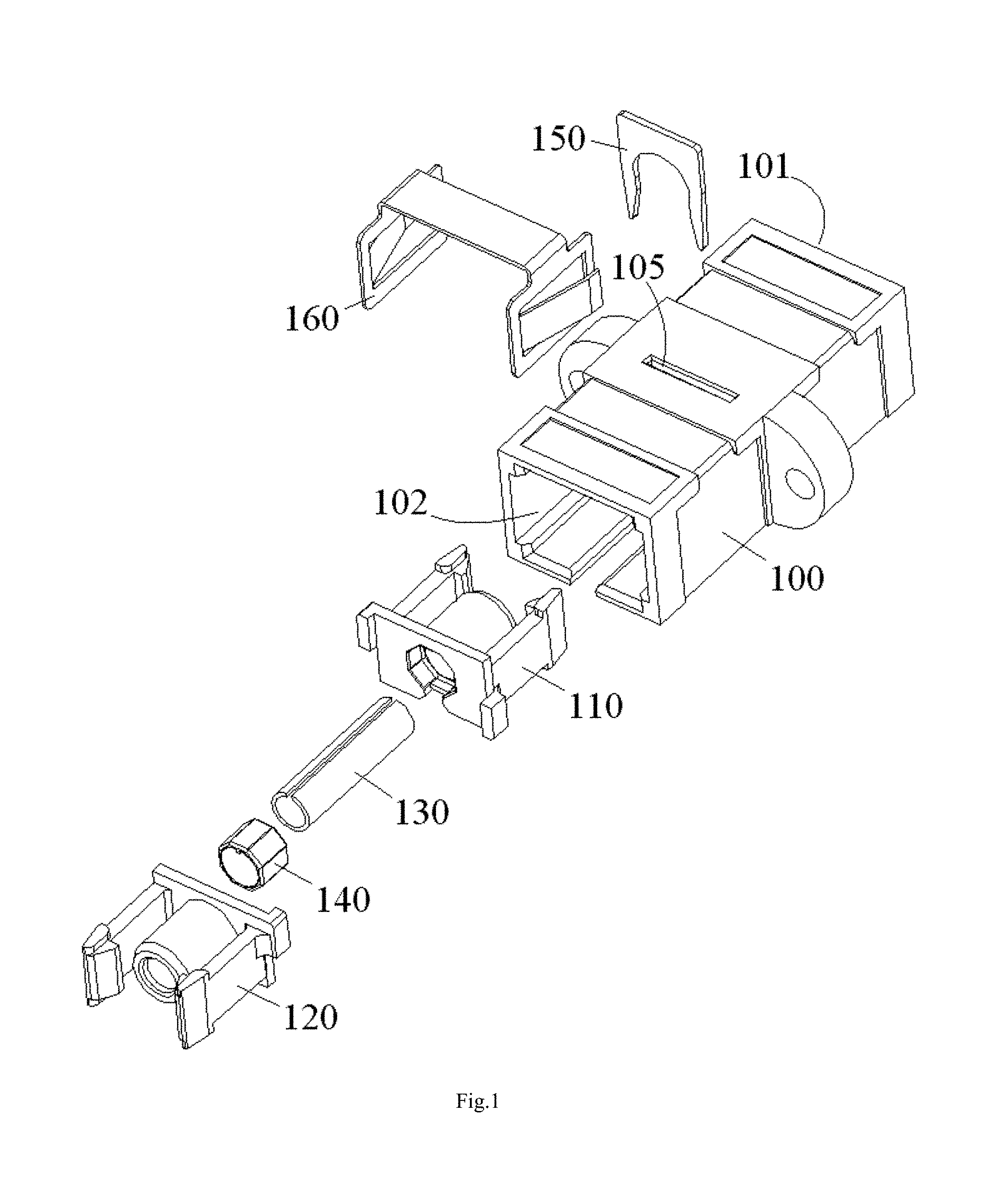
FIG. 1 is an illustrative exploded view of a fiber optic adapter according to a first exemplary embodiment of the present invention;
FIG. 2 is an illustrative perspective view of an adjustment element of the fiber optic adapter of FIG. 1;
FIG. 3 is an illustrative perspective view of an alignment sleeve of the fiber optic adapter of FIG. 1;
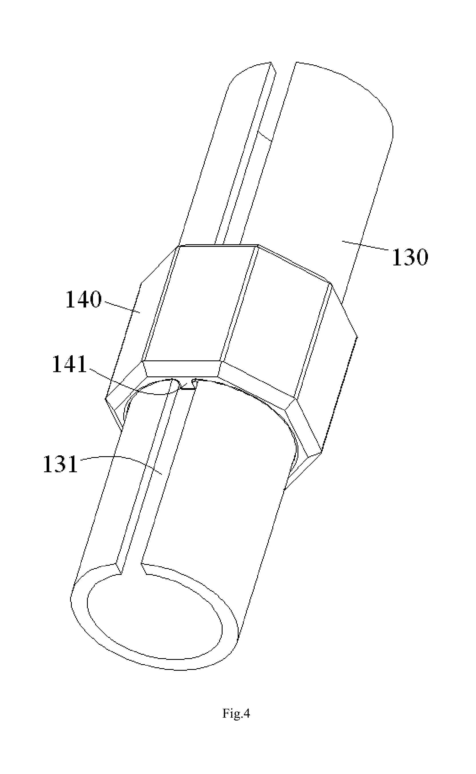
FIG. 4 is an illustrative view of an alignment sleeve assembly formed by assembling the adjustment element of FIG. 2 to the alignment sleeve of FIG. 3;
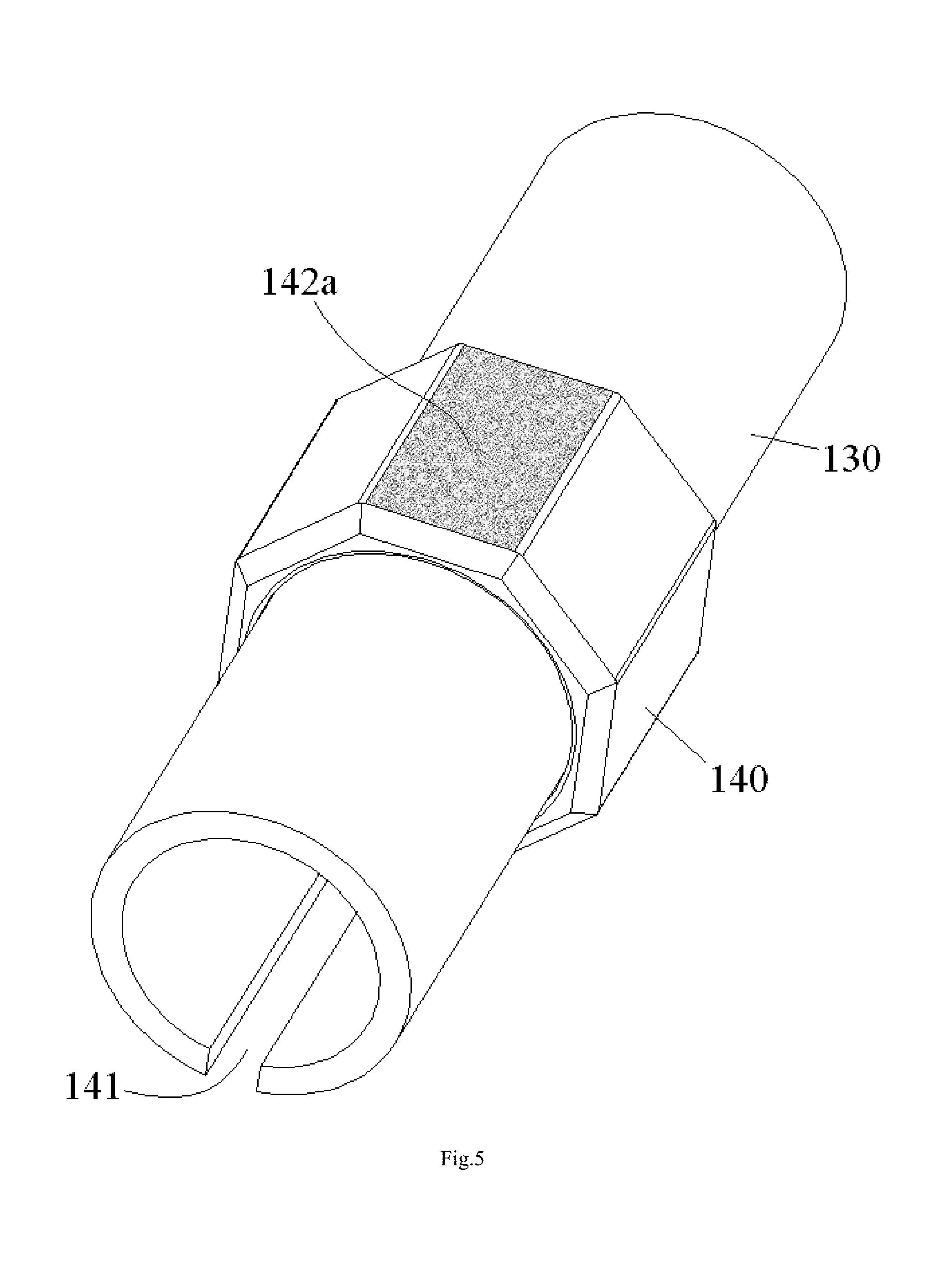
FIG. 5 is an illustrative view of a first circumferential angle mark formed on an outer surface of the adjustment element of the alignment sleeve assembly of FIG. 4;
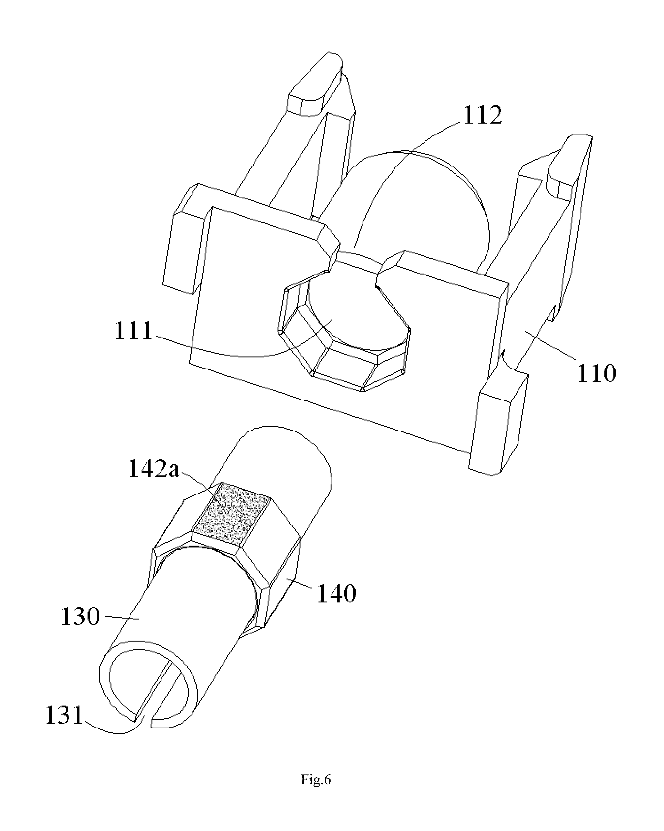
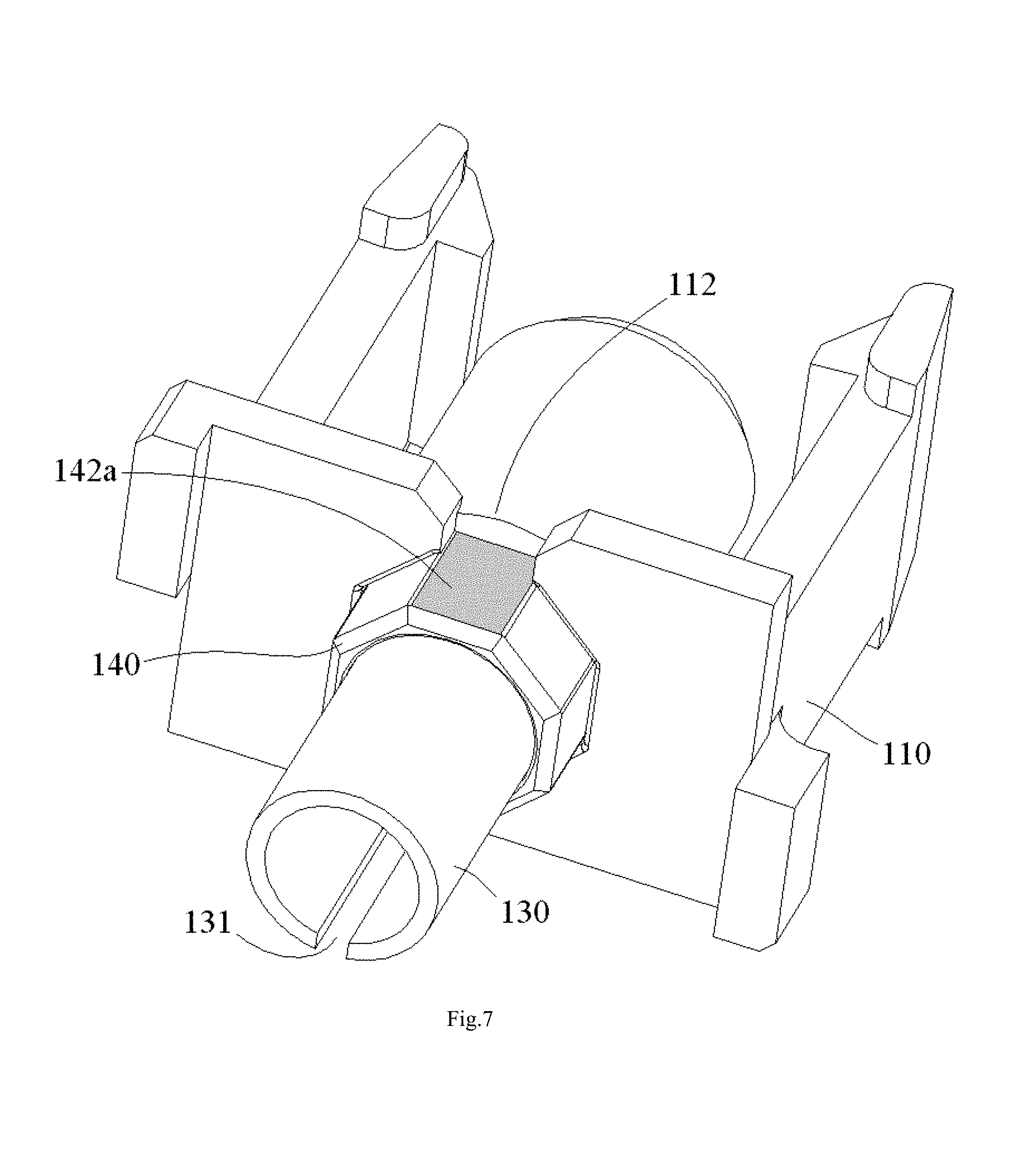
FIGS. 6 and 7 are illustrative views of mounting the alignment sleeve assembly of FIG. 5 to a first mating retainer;
FIGS. 8 and 9 are illustrative views of assembling the first mating retainer of FIG. 7 to a second mating retainer;
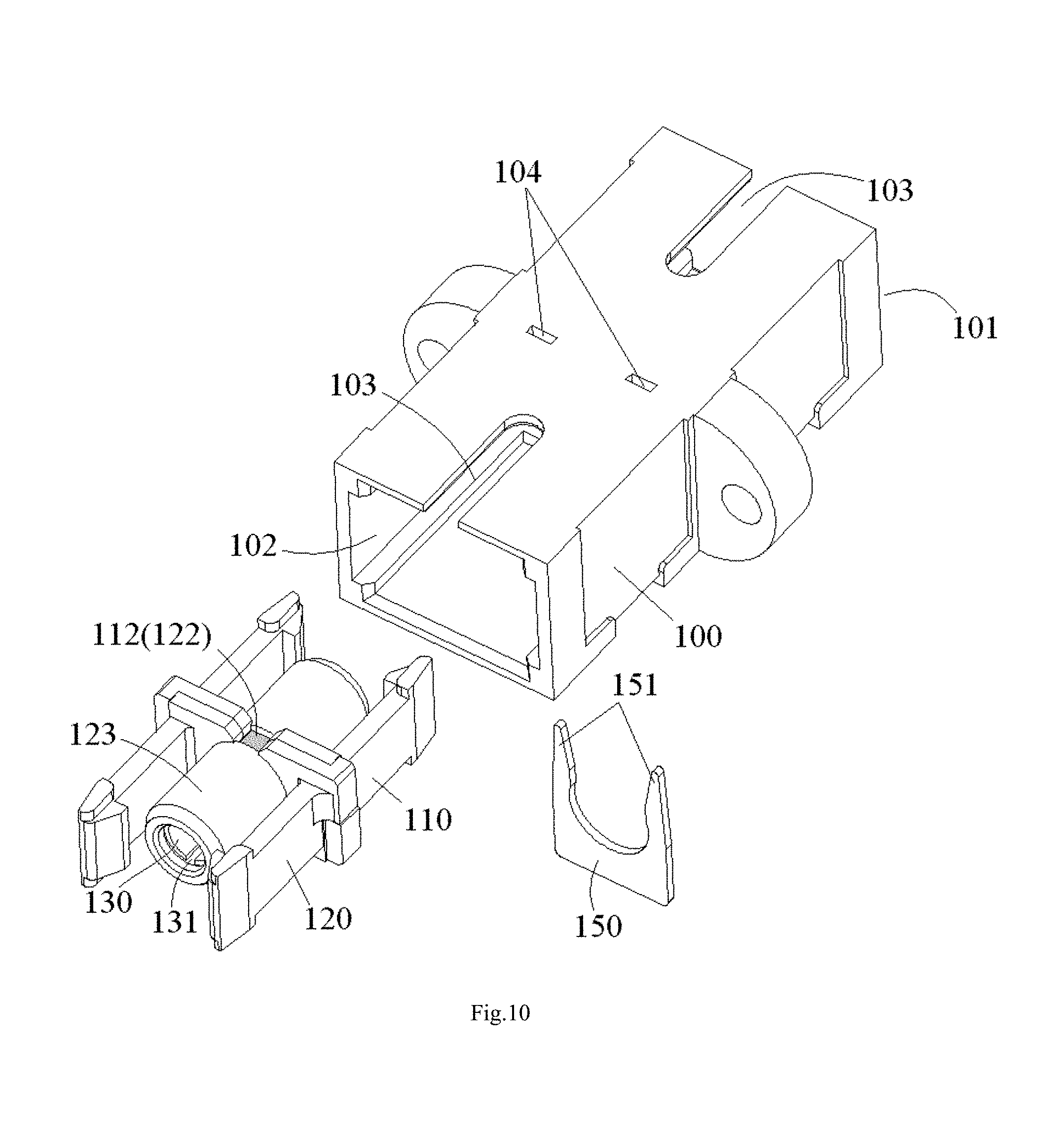
FIG. 10 is an illustrative view of mounting the assembled first and second mating retainers of FIG. 9 to a housing;
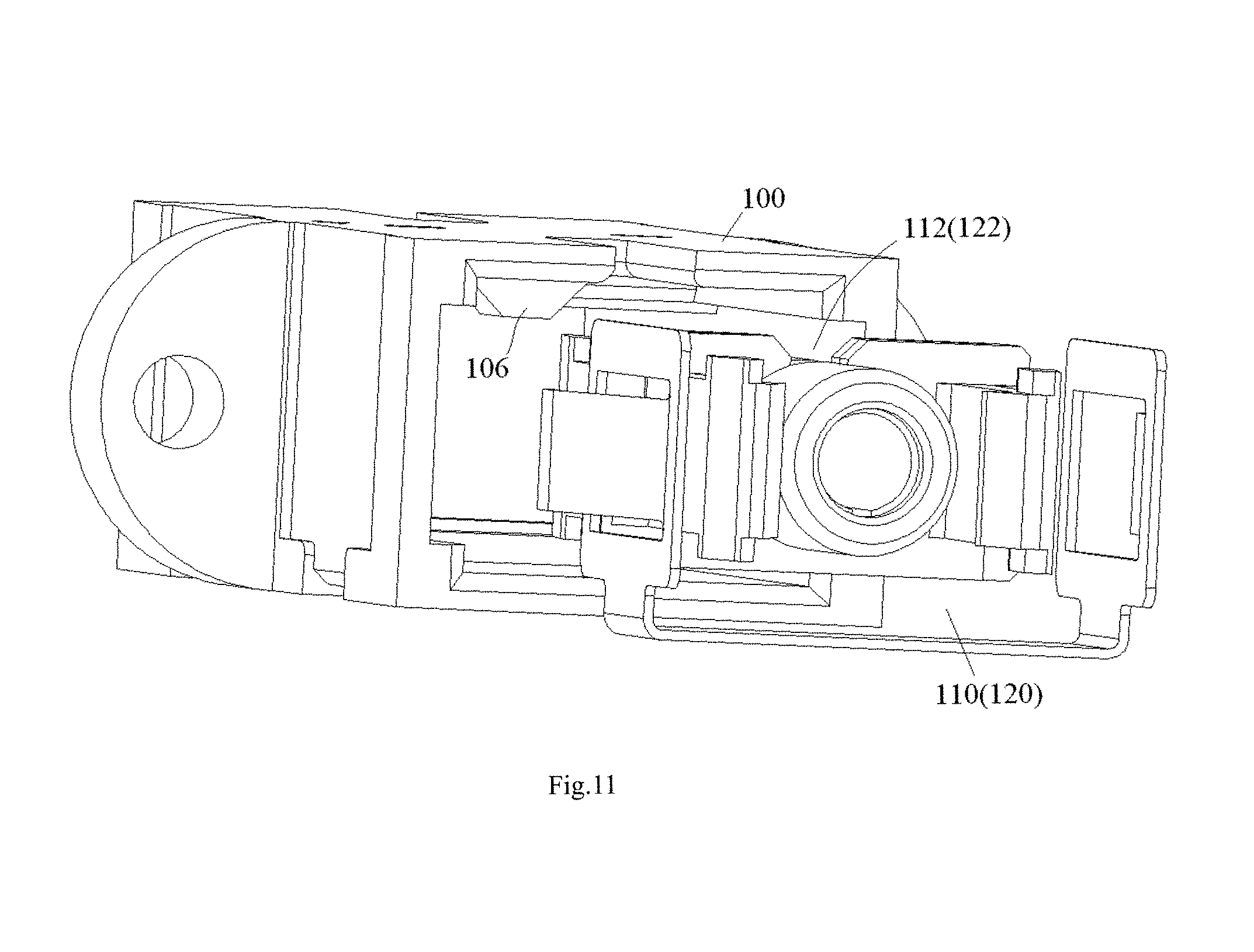
FIG. 11 shows a foolproof installation structure between the housing and the mating retainer;
FIG. 12 is an illustrative view of mounting an elastic snapper on the housing;
FIG. 13 is an illustrative perspective view of the assembled fiber optic adapter according to the first exemplary embodiment of the present invention;
FIG. 14 is an illustrative perspective view of a fiber optic adapter according to a second exemplary embodiment of the present invention, wherein an alignment sleeve assembly is mounted to a first mating retainer;
FIG. 15 is an illustrative view of assembling the first mating retainer of FIG. 14 to a second mating retainer; and
FIG. 16 is an illustrative perspective view of an assembled fiber optic adapter according to a second exemplary embodiment of the present invention.
DETAILED DESCRIPTION OF PREFERRED EMBODIMENTS OF THE INVENTION
Exemplary embodiments of the present disclosure will be described hereinafter in detail with reference to the attached drawings, wherein the like reference numerals refer to the like elements. The present disclosure may, however, be embodied in many different forms and should not be construed as being limited to the embodiment set forth herein; rather, these embodiments are provided so that the present disclosure will be thorough and complete, and will fully convey the concept of the disclosure to those skilled in the art.
In the following detailed description, for purposes of explanation, numerous specific details are set forth in order to provide a thorough understanding of the disclosed embodiments. It will be apparent, however, that one or more embodiments may be practiced without these specific details. In other instances, well-known structures and devices are schematically shown in order to simplify the drawing.
According to a general concept of the present invention, there is provided a fiber optic adapter, comprising: a mating retainer; an alignment sleeve received in the mating retainer, a ferrule of a fiber optic connector being adapted to be inserted into the alignment sleeve through an insertion port of the fiber optic adapter; and an adjustment element configured to adjust a circumferential angle of the alignment sleeve relative to the mating retainer to a predetermined circumferential angle and hold the alignment sleeve at the predetermined circumferential angle relative to the mating retainer.
According to another general concept of the present invention, there is provided an alignment sleeve assembly, comprising: an alignment sleeve adapted to be received in a mating retainer of a fiber optic adapter; and an adjustment element configured to adjust a circumferential angle of the alignment sleeve relative to the mating retainer to a predetermined circumferential angle and hold the alignment sleeve at the predetermined circumferential angle relative to the mating retainer.
First Embodiment
FIGS. 1-13 show a fiber optic adapter according to a first exemplary embodiment of the present invention.
FIG. 1 is an illustrative exploded view of the fiber optic adapter according to a first exemplary embodiment of the present invention.
As shown in FIG. 1, it shows a LC type of fiber optic adapter. The fiber optic adapter mainly comprises a housing 100, a mating retainer 110, 120, an alignment sleeve 130 and an adjustment element 140.
As shown in FIG. 1, the mating retainer 110, 120 comprises a first mating retainer 110 and a second mating retainer 120 capable of being assembled together. The mating retainer 110, 120 is configured to receive the alignment sleeve 130 therein and lock coupled fiber optic connectors (not shown) in place. A ferrule of one of the fiber optic connector is adapted to be inserted into the alignment sleeve 130 through an insertion port 101, 102 of the fiber optic adapter. In this way, fiber cores of the fiber optic connectors are coupled with each other in the alignment sleeve 130.
FIG. 2 is an illustrative perspective view of an adjustment element 140 of the fiber optic adapter of FIG. 1; FIG. 3 is an illustrative perspective view of an alignment sleeve 130 of the fiber optic adapter of FIG. 1; FIG. 4 is an illustrative view of an alignment sleeve assembly formed by assembling the adjustment element 140 of FIG. 2 to the alignment sleeve 130 of FIG. 3.
As shown in FIGS. 1-4, in an embodiment, the adjustment element 140 is configured to adjust a circumferential angle of the alignment sleeve 130 relative to the mating retainer 110, 120 to a predetermined circumferential angle and hold the alignment sleeve 130 at the predetermined circumferential angle relative to the mating retainer 110, 120.
In an embodiment, when the alignment sleeve 130 is held at the predetermined circumferential angle relative to the mating retainer 110, 120, an alignment error between fiber cores of fibers, which are inserted into the alignment sleeve 130 fiber optic adapter, of a pair of fiber optic connectors is minimal, that is, an insertion loss is minimal. In this way, it is possible to minimize the insertion loss of the fiber optic connectors by adjusting and positioning the circumferential angle of the alignment sleeve 130 with respect to the mating retainer 110, 120.
In the first embodiment shown in FIGS. 1-13, only a single alignment sleeve 130 is received in the mating retainer 110, 120. The alignment sleeve 130 is configured to align ferrules of the pair of fiber optic connectors to be coupled. Thereby, the fiber optic adapter of FIG. 1 is adapted to couple only a pair of fiber optic connectors at the same time. However, the present invention is not limited to this; the fiber optic adapter may be configured to couple a plurality of pairs of fiber optic connectors at the same time.
Hereafter, it will describe in detail features and assembling operation of components of the optical fiber adapter with reference to drawings.
As shown in FIGS. 2-4, in an embodiment, the adjustment element 140 is adapted to be sleeved on the alignment sleeve 130. A radial protrusion 141 is formed on an inner wall of the adjustment element 140 and adapted to be inserted into a longitudinal slot 131 of the alignment sleeve 130, so that the alignment sleeve 130 is capable of being rotated with the alignment element 140, and the circumferential angle of the alignment sleeve 130 relative to the mating retainer 110, 120 is adjusted by rotating the adjustment element 140.
In an exemplary embodiment of the present invention, the radial protrusion 141 of the adjustment element 140 has a width in a circumferential direction equal to or slightly less than a width of the longitudinal slot 131 of the alignment sleeve 130 in the circumferential direction. In this way, once the radial protrusion 141 of the adjustment element 140 is inserted into the longitudinal slot 131 of the alignment sleeve 130, the alignment sleeve 130 is unable to be rotated in a circumferential direction relative to the adjustment element 140, or is only able to be rotated in a very small angle range in the circumferential direction relative to the adjustment element 140, for example, is only able to be rotated in a range of .+-.30 degrees, preferably, in a range of .+-.20 degrees, more preferably, in a range of .+-.10 degrees.
FIG. 5 is an illustrative view of a first circumferential angle mark 142a formed on an outer surface of the adjustment element 140 of the alignment sleeve assembly of FIG. 4.
As shown in FIGS. 4 and 5, in an embodiment, before the alignment sleeve 130 is mounted to the mating retainer 110, 120, the alignment sleeve 130 is adjusted to the optimum circumferential angle, at which the insertion loss of the optical fiber connectors is minimal, by the adjustment element 140.
FIGS. 6 and 7 are illustrative views of mounting the alignment sleeve assembly of FIG. 5 to the first mating retainer 110; FIGS. 8 and 9 are illustrative views of assembling the first mating retainer 110 of FIG. 7 to the second mating retainer 120.
As shown in FIGS. 5-9, in an embodiment, after the alignment sleeve 130 is adjusted to the optimum circumferential angle at which the insertion loss of the optical fiber connectors is minimal, a first circumferential angle mark 142a is provided on the outer surface 142 of the adjustment element 140. The first circumferential angle mark 142a is used to identify the optimum circumferential angle of the alignment sleeve 130 relative to the mating retainer 110. In an embodiment, when the alignment sleeve 130 is adjusted to the optimum circumferential angle by the adjustment element 140, the first circumferential angle mark 142a of the adjustment element 140 should be aligned to a second circumferential angle mark 112, 122 formed on the mating retainer 110, 120. In this way, during the alignment sleeve assembly of FIG. 5 is mounted to the mating retainer 110, 120, as long as the first circumferential angle mark 142a of the adjustment element 140 is aligned to the second circumferential angle mark 112, 122 of the mating retainer 110, 120, it may ensure that the alignment sleeve 130 is positioned at the optimum circumferential angle, at which the insertion loss of the optical fiber connectors is minimal, with respect to the mating retainer 110.
In an exemplary embodiment of the present invention, as shown in FIGS. 5-9, the adjustment element 140 is constructed as a polygonal prism with a polygon cross section exhibiting, for example, triangle, quadrilateral, pentagon, hexagon or any other shape with more edges. In another embodiment, the adjustment element 140 may have but not limited to a regular polygon cross section. A positioning slot 111, 121, corresponding to an outer profile of the adjustment element 140, is formed in mating retainer 110, 120. The adjustment element 140 is adapted to be fixed in positioning slot 111, 121 of the mating retainer 110, 120, so as to hold the alignment sleeve 130 at the optimum circumferential angle relative to the mating retainer 110, 120.
Please be noted that the present invention is not limited to the illustrated embodiment, the adjustment element may be fixed on the mating retainer by any other suitable way. For example, in another embodiment, the adjustment element 140 is formed with multiple spline keys; the mating retainer 110, 120 is formed with multiple spline slots. The multiple spline keys of the adjustment element 140 are adapted to be fitted in the multiple spline slots of the mating retainer 110, 120, so as to hold the alignment sleeve 130 at the optimum circumferential angle relative to the mating retainer 110, 120.
FIG. 10 is an illustrative view of mounting the assembled first and second mating retainers 110, 120 of FIG. 9 to a housing 100.
As shown in FIGS. 9 and 10, after the first and second mating retainers 110, 120 are assembled together, the entire mating retainer 110, 120 is mounted in the housing 100.
As shown in FIG. 10, in an embodiment, an alignment slot 103, configured to mate with a sliding block (not shown) on the fiber optic connector, is formed in the housing 100, so as to ensure that the fiber optic connector is inserted into the fiber optic adapter in a correct orientation relative to the fiber optic adapter. When the alignment sleeve 130 is adjusted to and kept at the optimum circumferential angle by the adjustment element 140, the first circumferential angle mark 142a and the second circumferential angle mark 112, 122 are aligned to the alignment slot 103 of the housing 100. In this way, during the mating retainer 110, 120 is mounted to the housing 100, as long as the first circumferential angle mark 142a and the second circumferential angle mark 112, 122 are aligned to the alignment slot 103 of the housing 100, it may ensure that the mating retainer 110, 120 is correctly mounted in the housing 100.
FIG. 11 shows a foolproof installation structure between the housing 100 and the mating retainer 110, 120.
As shown in FIG. 11, in an embodiment, in order to prevent the mating retainer 110, 120 from being incorrectly mounted to (for example, reversely mounted to) the housing 100, a foolproof installation structure between the housing 100 and the mating retainer 110, 120 is designed.
As shown in FIG. 11, in an embodiment, the second circumferential angle mark 112, 122 of the mating retainer 110, 120 comprises a notch formed in the mating retainer 110, 120. A foolproof assembly protrusion 106, configured to mate with the notch of the mating retainer 110, 120, is formed on an inner wall of the housing 100. The mating retainer 110, 120 is allowed to be assembled into the housing 100 only when the foolproof assembly protrusion 106 of the housing 100 is aligned to the notch of the mating retainer 110, 120. In other words, if the foolproof assembly protrusion 106 of the housing 100 is not aligned to the notch of the mating retainer 110, 120, the retainer 110, 120 is not allowed to be assembled into the housing 100. In this way, it may effectively prevent the mating retainer 110, 120 from being incorrectly mounted to (for example, reversely mounted to) the housing 100.
As shown in FIGS. 1 and 10, the fiber optic adapter may further comprise a fixation element 150 adapted to be mounted on the housing 100 and hold a tube-like body 123 of the mating retainer 110, 120, so as to prevent the mating retainer 110, 120 from being pulled out of the housing 100.
In an embodiment, the fixation element 150 is inserted into the housing 100 through a slot 105 (see FIG. 1) formed in the housing 100. Two legs of the fixation element 150 are inserted into two holes 104 formed in the housing 100. As a result, the tube-like body 123 of the mating retainer 110, 120 is clamped and fixed by the fixation element 150.
FIG. 12 is an illustrative view of mounting an elastic snapper 160 on the housing 100; FIG. 13 is an illustrative perspective view of the assembled fiber optic adapter according to the first exemplary embodiment of the present invention.
As shown in FIGS. 12-13, in an embodiment, the fiber optic adapter may further comprise an elastic snapper 160 mounted on the housing 100 and configured to lock the fiber optic adapter in a fixation installation position.
In the first embodiment shown in FIGS. 1-13, the mating retainer 110, 120 comprises the first mating retainer 110 and the second mating retainer 120 capable of being assembled together. The positioning slot 111, 121 comprises a first positioning slot 111 and a second positioning slot 121, aligned to each other, formed in mating ends of the first mating retainer 110 and the second mating retainer 120, respectively. The second circumferential angle mark 112, 122 comprises a first notch 112 and a second notch 122, aligned to each other, formed in the mating ends of the first mating retainer 110 and the second mating retainer 120, respectively.
Also, it should be appreciated that, in some conditions, it is unnecessary to set the insertion loss of the fiber optic connectors inserted into the fiber optic adapter to be minimal, but it is necessary to maintain the longitudinal slot 131 of the alignment sleeve 130 at a specified circumferential angle (a predetermined orientation) with respect to the mating retainer 110, 120. In this case, it is also possible to use the adjustment element 130 to adjust the alignment sleeve 130 to the specified circumferential angle and kept at the specified circumferential angle.
Second Embodiment
FIGS. 14-16 show a fiber optic adapter according to a second exemplary embodiment of the present invention.
FIG. 14 is an illustrative perspective view of a fiber optic adapter according to a second exemplary embodiment of the present invention, wherein an alignment sleeve assembly is mounted to a first mating retainer 210; FIG. 15 is an illustrative view of assembling the first mating retainer 210 of FIG. 14 to a second mating retainer 220; and FIG. 16 is an illustrative perspective view of an assembled fiber optic adapter according to a second exemplary embodiment of the present invention.
As shown in FIGS. 14-16, in the second embodiment, the fiber optic adapter is adapted to couple a plurality of pairs of fiber optic connectors at the same time. A plurality of alignment sleeves 230, configured to align ferrules of the pairs of fiber optic connectors, are received in the mating retainer 210, 220.
Also, in the second embodiment shown in FIGS. 14-16, the fiber optic adapter does not comprise a housing, since the mating retainer 210, 220 is served as a body of the fiber optic adapter and is directly exposed outside.
In the second embodiment shown in FIGS. 14-16, the mating retainer 210, 220 comprises a first mating retainer 210 and a second mating retainer 220 capable of being assembled together. The mating retainer 210, 220 is configured to receive the alignment sleeves 130 therein and lock coupled fiber optic connectors (not shown) in place. A ferrule of a fiber optic connector is adapted to be inserted into the alignment sleeve 230 through an insertion port 201, 202 of the fiber optic adapter. In this way, fiber cores of the fiber optic connectors are coupled with each other in the alignment sleeve 230.
In the second embodiment shown in FIGS. 14-16, the adjustment element 240 is configured to adjust a circumferential angle of the alignment sleeve 230 relative to the mating retainer 210, 220 to a predetermined circumferential angle and hold the alignment sleeve 230 at the predetermined circumferential angle relative to the mating retainer 210, 220.
In the second embodiment shown in FIGS. 14-16, when the alignment sleeve 230 is held at the predetermined circumferential angle relative to the mating retainer 210, 220, an alignment error between fiber cores of fibers, inserted into the alignment sleeve 130 fiber optic adapter, of a pair of fiber optic connectors is minimal, that is, an insertion loss is minimal. In this way, it is possible to minimize the insertion loss of the fiber optic connectors by adjusting and positioning the circumferential angle of the alignment sleeve 230 with respect to the mating retainer 210, 220.
Hereafter, it will describe in detail features and operation of assembling components of the optical fiber adapter with reference to drawings.
In the second embodiment shown in FIGS. 14-16, the adjustment element 240 is adapted to be sleeved on the alignment sleeve 230. A radial protrusion 241 is formed on an inner wall of the adjustment element 240 and adapted to be inserted into a longitudinal slot 231 of the alignment sleeve 230, so that the alignment sleeve 230 is capable of being rotated with the alignment element 240, and the circumferential angle of the alignment sleeve 230 relative to the mating retainer 210, 220 is capable of being adjusted by rotating the adjustment element 240.
In an exemplary embodiment of the present invention, the radial protrusion 241 of the adjustment element 240 has a width in a circumferential direction equal to or slightly less than a width of the longitudinal slot 231 of the alignment sleeve 230 in the circumferential direction. In this way, once the radial protrusion 241 of the adjustment element 240 is inserted into the longitudinal slot 231 of the alignment sleeve 230, the alignment sleeve 230 is unable to be rotated in the circumferential direction relative to the adjustment element 240, or is only able to be rotated in a very small angle range in the circumferential direction relative to the adjustment element 240, for example, is only able to be rotated in a range of .+-.30 degrees, preferably, in a range of .+-.20 degrees, more preferably, in a range of .+-.10 degrees.
In the second embodiment shown in FIGS. 14-16, before the alignment sleeve 230 is mounted to the mating retainer 210, 220, the alignment sleeve 230 is adjusted to the optimum circumferential angle, at which the insertion loss of the optical fiber connectors is minimal, by the adjustment element 240.
In the second embodiment shown in FIGS. 14-16, after the alignment sleeve 230 is adjusted to the optimum circumferential angle at which the insertion loss of the optical fiber connectors is minimal, a first circumferential angle mark 242a is provided on the outer surface 242 of the adjustment element 240. The first circumferential angle mark 242a is used to identify the optimum circumferential angle of the alignment sleeve 230 relative to the mating retainer 210. In an embodiment, when the alignment sleeve 230 is adjusted to the optimum circumferential angle by the adjustment element 240, the first circumferential angle mark 242a of the adjustment element 240 should be aligned to a second circumferential angle mark 212, 222 formed on the mating retainer 210, 220. In this way, during the alignment sleeve assembly of FIG. 14 is mounted to the mating retainer 210, 220, as long as the first circumferential angle mark 242a of the adjustment element 240 is aligned to the second circumferential angle mark 212, 222 of the mating retainer 210, 220, it may ensure that the alignment sleeve 230 is positioned at the optimum circumferential angle, at which the insertion loss of the optical fiber connectors is minimal, with respect to the mating retainer 210, 220.
In the second embodiment shown in FIGS. 14-16, the adjustment element 240 is constructed as a polygonal prism with a polygon cross section exhibiting, for example, triangle, quadrilateral, pentagon, hexagon or any other shape with more edges. In another embodiment, the adjustment element 240 may have but not limited to a regular polygon cross section. A positioning slot 211, 221, corresponding to an outer profile of the adjustment element 240, is formed in mating retainer 210, 220. The adjustment element 240 is adapted to be fixed in positioning slot 211, 221 of the mating retainer 210, 220, so as to hold the alignment sleeve 230 at the optimum circumferential angle relative to the mating retainer 210, 220.
Please be noted that the present invention is not limited to the illustrated embodiment, the adjustment element may be fixed on the mating retainer by any other suitable way. For example, in another embodiment, the adjustment element 240 is formed with multiple spline keys; the mating retainer 210, 220 is formed with multiple spline slots. The multiple spline keys of the adjustment element 240 are adapted to be fitted in the multiple spline slots of the mating retainer 210, 220, so as to hold the alignment sleeve 230 at the optimum circumferential angle relative to the mating retainer 210, 220.
In the second embodiment shown in FIGS. 14-16, the second circumferential angle mark 212, 222 of the mating retainer 210, 220 is a notch formed in the mating retainer 210, 220.
In the second embodiment shown in FIGS. 14-16, the mating retainer 210, 220 comprises a first mating retainer 210 and a second mating retainer 220 capable of being assembled together. The positioning slot 211, 221 comprises a first positioning slot 211 and a second positioning slot 221, aligned to each other, formed in mating ends of the first mating retainer 210 and the second mating retainer 220, respectively. The second circumferential angle mark 212, 222 comprises a first notch 212 and a second notch 222, aligned to each other, formed in the mating ends of the first mating retainer 210 and the second mating retainer 220, respectively.
The first mating retainer 210 and the second mating retainer 220 are coupled with each other in a snap-fit manner. In an exemplary embodiment, the first mating retainer 210 is provided with a plurality of first engagement protrusions 251 and a plurality of first engagement recesses 252, and the second mating retainer 220 is provided with a plurality of second engagement protrusions 253, which are engaged with the plurality of first engagement recesses 252, respectively, and a plurality of second engagement recesses 254, which are engaged with the plurality of first engagement protrusions 252, respectively.
Furthermore, the first mating retainer 210 is provided with at least one first guiding protrusions 255 and at least one first guiding recesses 256, and the second mating retainer 220 is provided with at least one second guiding protrusions, which are engaged with the plurality of first engagement recesses 256, respectively, and at least one second guiding recesses, which are engaged with the plurality of first engagement protrusions 255, respectively.
Also, it should be appreciated that, in some conditions, it is unnecessary to set the insertion loss of the fiber optic connectors inserted into the fiber optic adapter to be minimal, but it is necessary to maintain the longitudinal slot 231 of the alignment sleeve 1230 at a specified circumferential angle (a predetermined orientation) with respect to the mating retainer 210, 220. In this case, it is also possible to use the adjustment element 230 to adjust the alignment sleeve 230 to the specified circumferential angle and kept at the specified circumferential angle.
It should be appreciated for those skilled in this art that the above embodiments are intended to be illustrated, and not restrictive. For example, many modifications may be made to the above embodiments by those skilled in this art, and various features described in different embodiments may be freely combined with each other without conflicting in configuration or principle.
Although several exemplary embodiments have been shown and described, it would be appreciated by those skilled in the art that various changes or modifications may be made in these embodiments without departing from the principles and spirit of the disclosure, the scope of which is defined in the claims and their equivalents.
As used herein, an element recited in the singular and proceeded with the word "a" or "an" should be understood as not excluding plural of said elements or steps, unless such exclusion is explicitly stated. Furthermore, references to "one embodiment" of the present invention are not intended to be interpreted as excluding the existence of additional embodiments that also incorporate the recited features. Moreover, unless explicitly stated to the contrary, embodiments "comprising" or "having" an element or a plurality of elements having a particular property may include additional such elements not having that property.
* * * * *
D00000
D00001
D00002
D00003
D00004
D00005
D00006
D00007
D00008
D00009
D00010
D00011
D00012

D00013
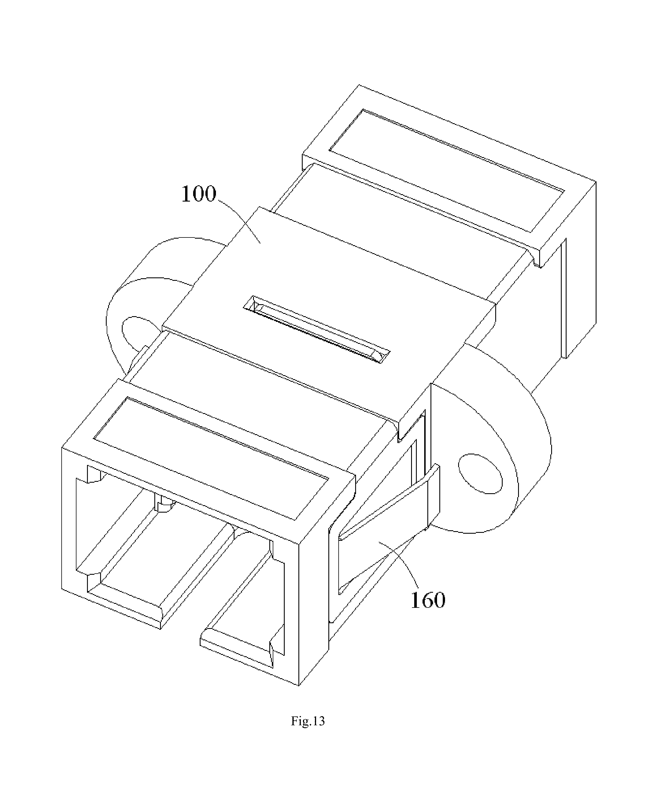
D00014
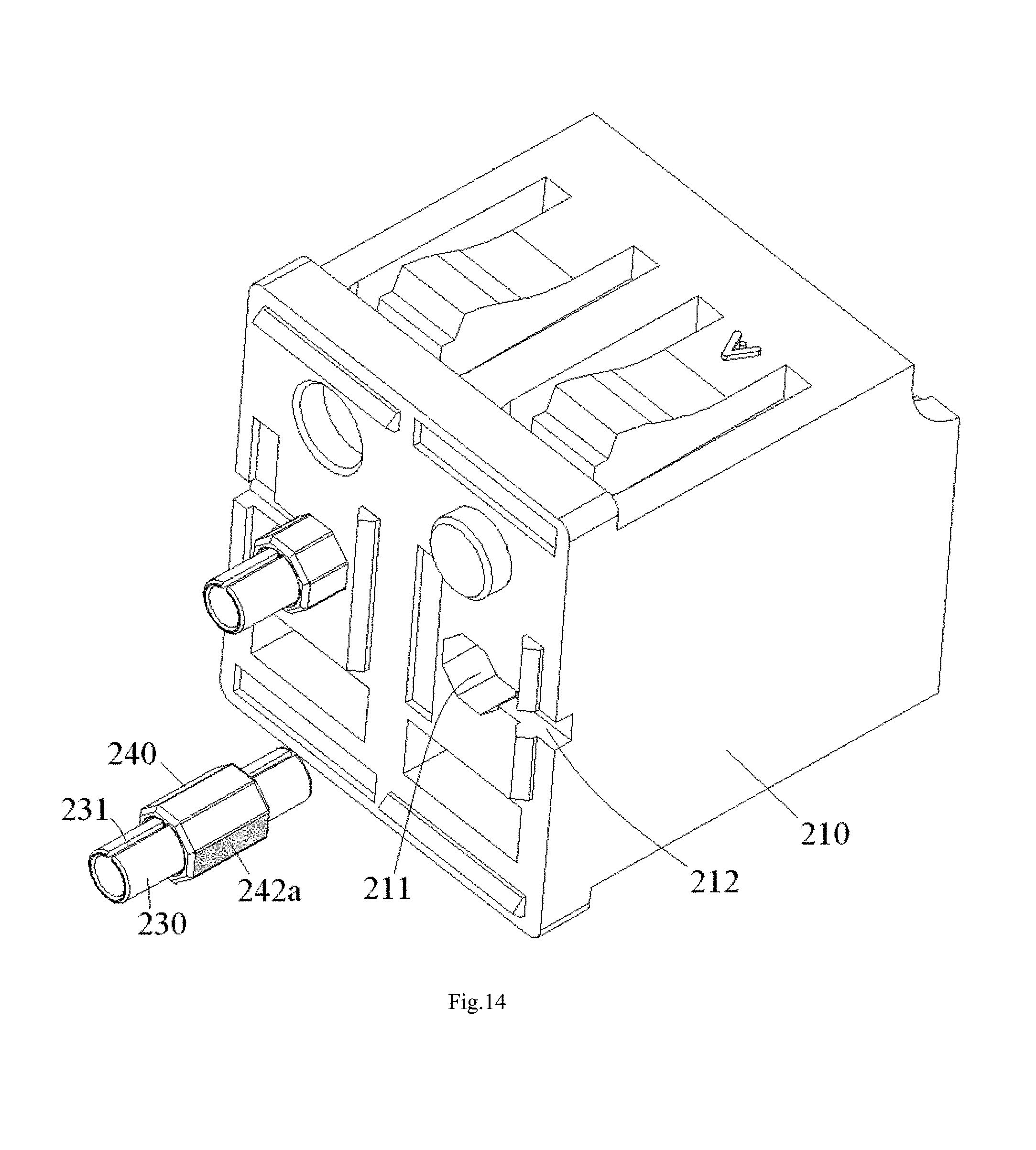
D00015
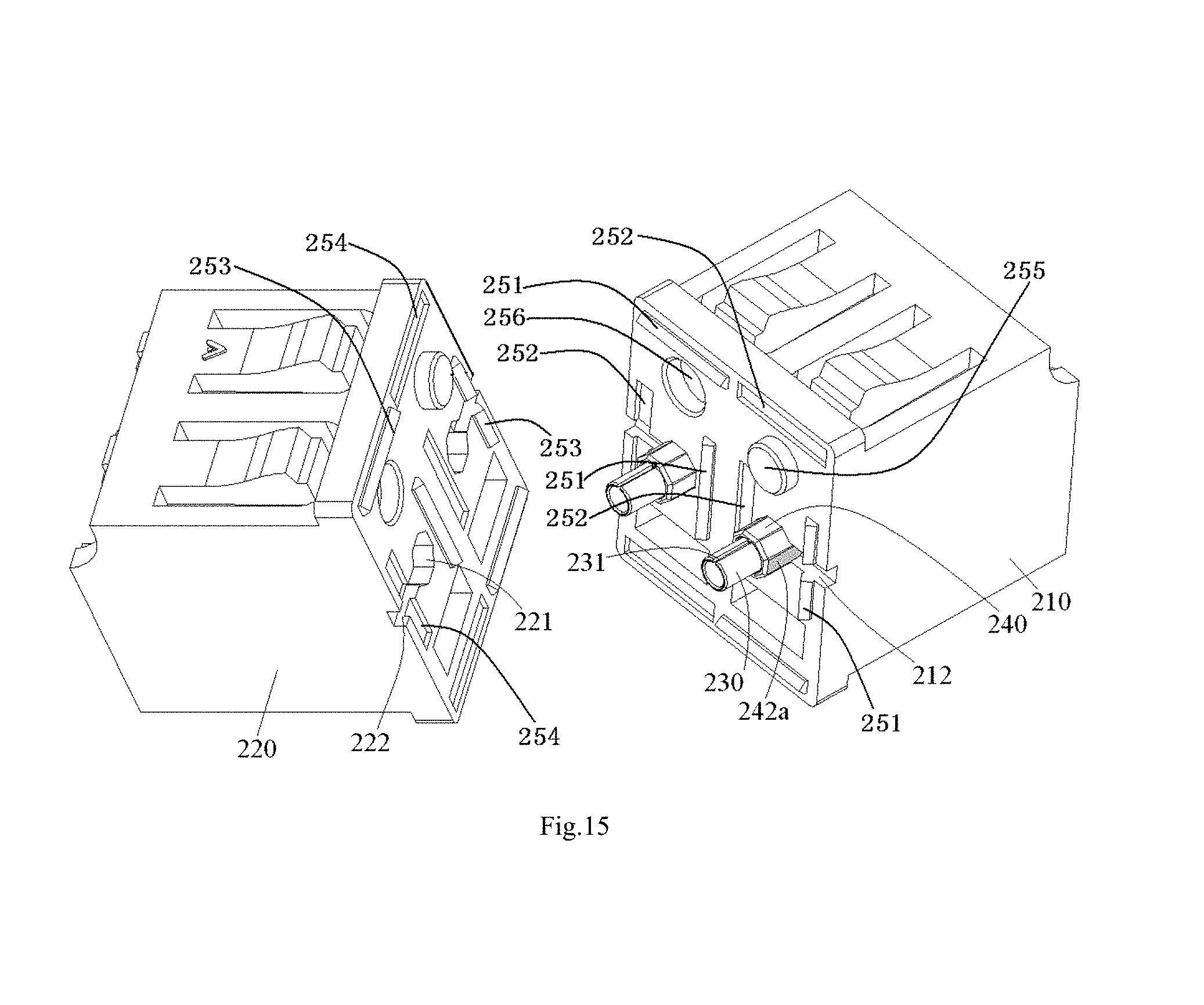
D00016
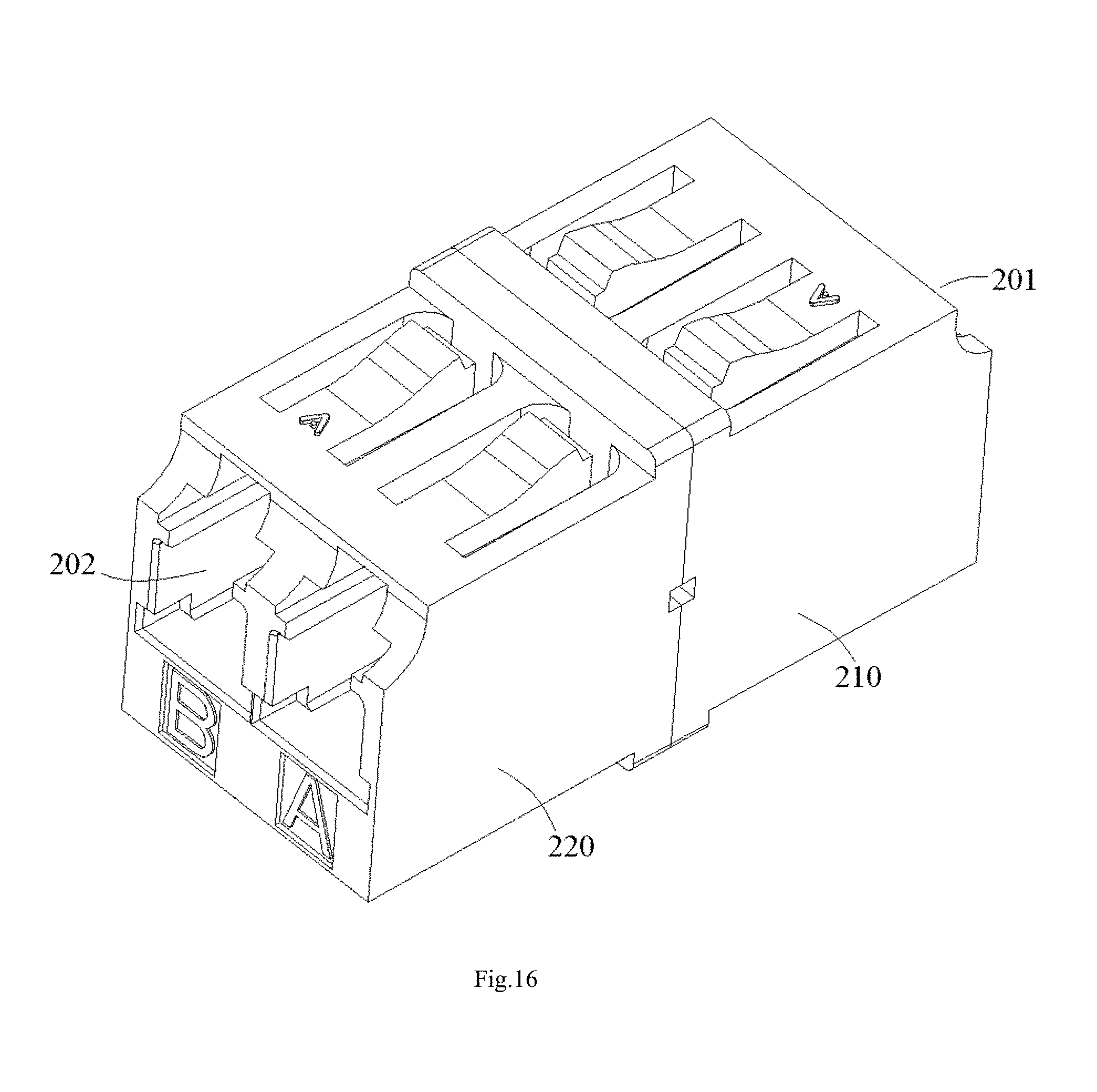
XML
uspto.report is an independent third-party trademark research tool that is not affiliated, endorsed, or sponsored by the United States Patent and Trademark Office (USPTO) or any other governmental organization. The information provided by uspto.report is based on publicly available data at the time of writing and is intended for informational purposes only.
While we strive to provide accurate and up-to-date information, we do not guarantee the accuracy, completeness, reliability, or suitability of the information displayed on this site. The use of this site is at your own risk. Any reliance you place on such information is therefore strictly at your own risk.
All official trademark data, including owner information, should be verified by visiting the official USPTO website at www.uspto.gov. This site is not intended to replace professional legal advice and should not be used as a substitute for consulting with a legal professional who is knowledgeable about trademark law.