System and method for estimating range to an RFID tag
Melville , et al.
U.S. patent number 10,302,756 [Application Number 15/837,585] was granted by the patent office on 2019-05-28 for system and method for estimating range to an rfid tag. This patent grant is currently assigned to AMTECH SYSTEMS, LLC. The grantee listed for this patent is Amtech Systems, LLC. Invention is credited to John Todd Elson, Michael George Melville.


View All Diagrams
| United States Patent | 10,302,756 |
| Melville , et al. | May 28, 2019 |
System and method for estimating range to an RFID tag
Abstract
A system is described for measuring distance between an RFID reader and an RFID backscatter tag, including an adaptive linear combiner, which is a tapped delay line with controllable weights on each tap, and outputs that are summed and subtracted from a reference to produce an error signal. After a sufficient number of cycles, the weight distribution indicates the delay of the received signal with respect to the reference, and by extension determines the distance between the tag and receiver.
| Inventors: | Melville; Michael George (Albuquerque, NM), Elson; John Todd (Albuquerque, NM) | ||||||||||
|---|---|---|---|---|---|---|---|---|---|---|---|
| Applicant: |
|
||||||||||
| Assignee: | AMTECH SYSTEMS, LLC
(Albuquerque, NM) |
||||||||||
| Family ID: | 53506720 | ||||||||||
| Appl. No.: | 15/837,585 | ||||||||||
| Filed: | December 11, 2017 |
Prior Publication Data
| Document Identifier | Publication Date | |
|---|---|---|
| US 20180100919 A1 | Apr 12, 2018 | |
Related U.S. Patent Documents
| Application Number | Filing Date | Patent Number | Issue Date | ||
|---|---|---|---|---|---|
| 15062766 | Mar 7, 2016 | 9841500 | |||
| 14734655 | Apr 19, 2016 | 9316728 | |||
| 13753338 | Jul 14, 2015 | 9081088 | |||
| 61594906 | Feb 3, 2012 | ||||
| Current U.S. Class: | 1/1 |
| Current CPC Class: | G06K 7/10425 (20130101); G06K 7/10366 (20130101); G01S 13/84 (20130101); G01S 13/584 (20130101); G01S 13/36 (20130101); G01S 13/08 (20130101); G01S 13/75 (20130101); G01S 13/325 (20130101); G01S 13/91 (20130101); G01S 13/878 (20130101) |
| Current International Class: | G06K 7/10 (20060101); G01S 13/08 (20060101); G01S 13/75 (20060101); G01S 13/91 (20060101); G01S 13/32 (20060101); G01S 13/36 (20060101); G01S 13/58 (20060101); G01S 13/84 (20060101); G01S 13/87 (20060101) |
References Cited [Referenced By]
U.S. Patent Documents
| 6184841 | February 2001 | Shober |
| 2005/0129139 | June 2005 | Jones |
| 2008/0150699 | June 2008 | Ohara |
| 2009/0007185 | January 2009 | Nix |
| 2010/0328073 | December 2010 | Nikitin |
| 2011/0187600 | August 2011 | Landt |
| 2011/0304441 | December 2011 | Roesner |
| 2014/0302869 | October 2014 | Rosenbaum |
Attorney, Agent or Firm: Snyder, Clark, Lesch & Chung, LLP
Parent Case Text
CROSS-REFERENCE TO RELATED APPLICATIONS
This application is a continuation of U.S. patent application Ser. No. 15/062,766 filed on Mar. 7, 2016; which application is a continuation of U.S. patent application Ser. No. 14/734,655 filed on Jun. 9, 2015, now U.S. Pat. No. 9,316,728; which is a continuation of U.S. patent application Ser. No. 13/753,338 filed Jan. 29, 2013, now U.S. Pat. No. 9,081,088; all three of which claim the benefit of provisional application Ser. No. 61/594,906 filed on Feb. 3, 2012, entitled "System and Method for Estimating Range to an RFID tag." The entire disclosures of the four applications listed above are hereby incorporated herein by reference.
Claims
What is claimed is:
1. A radio frequency identification (RFID) tag reader comprising: a transmitter configured to transmit a modulated signal to a tag via a first antenna; a receiver configured to receive a delayed modulated backscattered signal from the tag; and a linear adaptive combiner comprising a tapped delay line having a plurality of taps with controllable weights on each tap and outputs that are summed and subtracted from a reference to produce an error signal; wherein, for a first sample rate, modulation from the delayed modulated backscattered signal is input to said linear adaptive combiner, and modulation from said transmitted modulated signal is said reference to said linear adaptive combiner and wherein weights for said taps of said linear adaptive combiner are approximately zero for all of said taps except for a tap corresponding to the delay of the received modulated backscattered signal and wherein a first distance estimate between the tag and the first antenna corresponding to said first sample rate is determined from said delay; wherein for a second sample rate, modulation in the delayed modulated backscattered signal is input to said linear adaptive combiner, and modulation from said transmitted modulated signal is said reference to said linear adaptive combiner and wherein weights for said taps of said linear adaptive combiner are approximately zero for all of said taps except for a tap corresponding to the delay of the received modulated backscattered signal and wherein a second distance estimate between the tag and the first antenna corresponding to said second sample rate is determined from said delay; and wherein a final distance estimate between said first antenna and the tag is determined based on comparing said first and second distance estimates.
2. The RFID backscatter tag reader of claim 1, wherein said final distance estimate is determined by selecting the greater of said first and second distance estimates.
3. The RFID backscatter tag reader of claim 1, wherein said controllable weights are adjusted based on a least means square fit of said error signal.
4. The RFID backscatter tag reader of claim 1, wherein a horizontal distance estimate between said first antenna and said tag is determined based on said final distance estimate, a height of said first antenna and a first estimate of height of said tag relative to said height of said first antenna.
5. The RFID backscatter tag reader of claim 4, wherein said horizontal distance estimate between said first antenna and said tag is determined further based on revising said first estimate of height of said tag relative to said height of said first antenna.
6. The RFID backscatter tag reader of claim 1, wherein a horizontal distance estimate between said first antenna and said tag is determined based on said final distance estimate, a height of said first antenna, a distance between said first antenna and a second antenna at a second antenna height and a third distance estimate based on transmission of a second transmitted modulated signal to the tag via said second antenna and reception of a second delayed modulated backscattered signal at the second antenna from the tag.
7. The RFID backscatter tag reader of claim 6, wherein said horizontal distance estimate between said first antenna and said tag is further determined by estimating tag height relative to said height of said first antenna and said height of said second antenna.
8. A method for determining distance between a first antenna and a tag comprising: transmitting a modulated signal to the tag via the first antenna; receiving a delayed modulated backscattered signal from the tag; for a first sample rate, inputting modulation in the delayed modulated backscattered signal to an adaptive linear combiner, said adaptive linear combiner comprising a tapped delay line having a plurality of taps with controllable weights on each tap, and outputs that are summed and subtracted from a reference to produce an error signal; for said first sample rate, providing modulation from said transmitted modulated signal as a reference to said adaptive linear combiner; for said first sample rate, adjusting weights for said taps of said linear adaptive combiner such that said weights are approximately zero for all of said taps except for a tap corresponding to the delay of the received backscattered signal; determining a first distance estimate between the tag and the first antenna corresponding to said first sample rate based on said delay; for a second sample rate, inputting modulation in the delayed modulated backscattered signal to said adaptive linear combiner; for said second sample rate, providing modulation from said transmitted modulated signal as a reference to said adaptive linear combiner; for said second sample rate, adjusting weights for said taps of said linear adaptive combiner such that said weights are approximately zero for all of said taps except for a tap corresponding to the delay of the received backscattered signal; determining a second distance estimate between the tag and the first antenna corresponding to said second sample rate based on said delay; and comparing said first and second distance estimates to determine a final distance estimate between said first antenna and the tag.
9. The method of claim 8, further comprising selecting the greater of said first and second distance estimates to determine said final distance estimate.
10. The method of claim 8, further comprising adjusting said controllable weights based on a least means square fit of said error signal.
11. The method of claim 8, further comprising determining a horizontal distance estimate between said first antenna and said tag based on said final distance estimate, a height of said first antenna and a first estimate of a height of said tag relative to said height of said first antenna.
12. The method claim 11, wherein said horizontal distance estimate between said first antenna and said tag is further determined based on revising said first estimate of height of said tag relative to said height of said first antenna.
13. The method of claim 8, further comprising determining a horizontal distance estimate between said first antenna and said tag based on said final distance estimate, a height of said first antenna, a distance between said first antenna and a second antenna at a second antenna height and a third distance estimate based on transmission of a second transmitted modulated signal to the tag via said second antenna and reception from the tag of a second delayed modulated backscattered signal at the second antenna.
14. The method of claim 13, wherein said horizontal distance estimate between said first antenna and said tag is further determined by estimating tag height relative to said height of said first antenna and said height of said second antenna.
Description
BACKGROUND OF THE INVENTION
Estimation of the distance to a tag in a Radio Frequency Identification (RFID) system is a useful feature. It would provide for an improved method of cross-lane discrimination in RFID tolling stations, while also providing a platform to estimate vehicle speeds in the same type of application. While there are many techniques developed in prior art for range estimation, this approach uses digital components in the receiver. Patents in the general field include U.S. Pat. Nos. 6,600,443; 6,476,756 and 7,030,361.
Past methods include angle of arrival at multiple receivers, received signal strength indicator (RSSI), and variation of phase in a received signal. Each of these has their strengths but the present method particularly applies to a system with discrete (i.e. digitally sampled) signal inputs.
BRIEF DESCRIPTION OF THE FIGURES
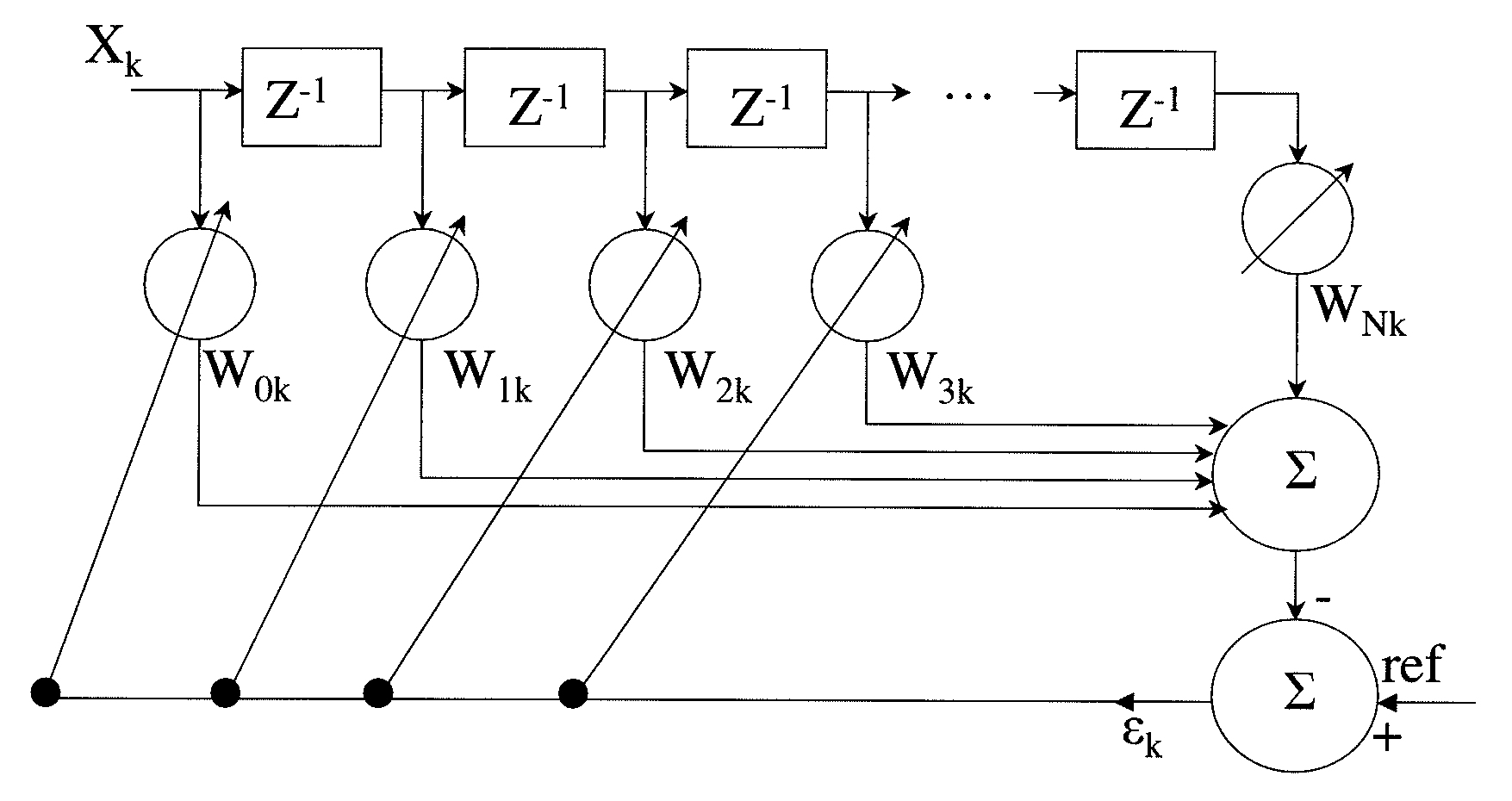
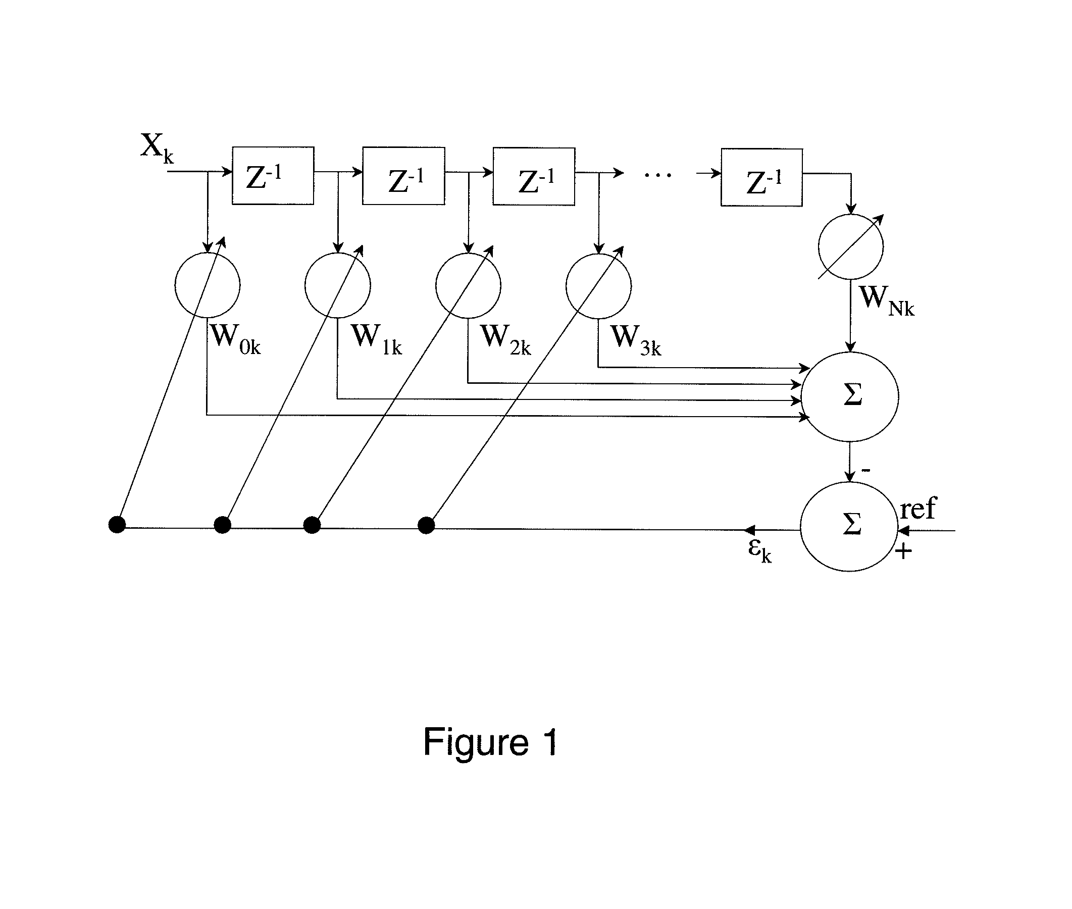
FIG. 1 is block diagram of an embodiment of a system for distance measurement;
FIG. 2 shows a reference signal (upper graph) and backscattered signal containing a small amount of noise and lagging by 15 samples or 15 nsec. (lower graph)
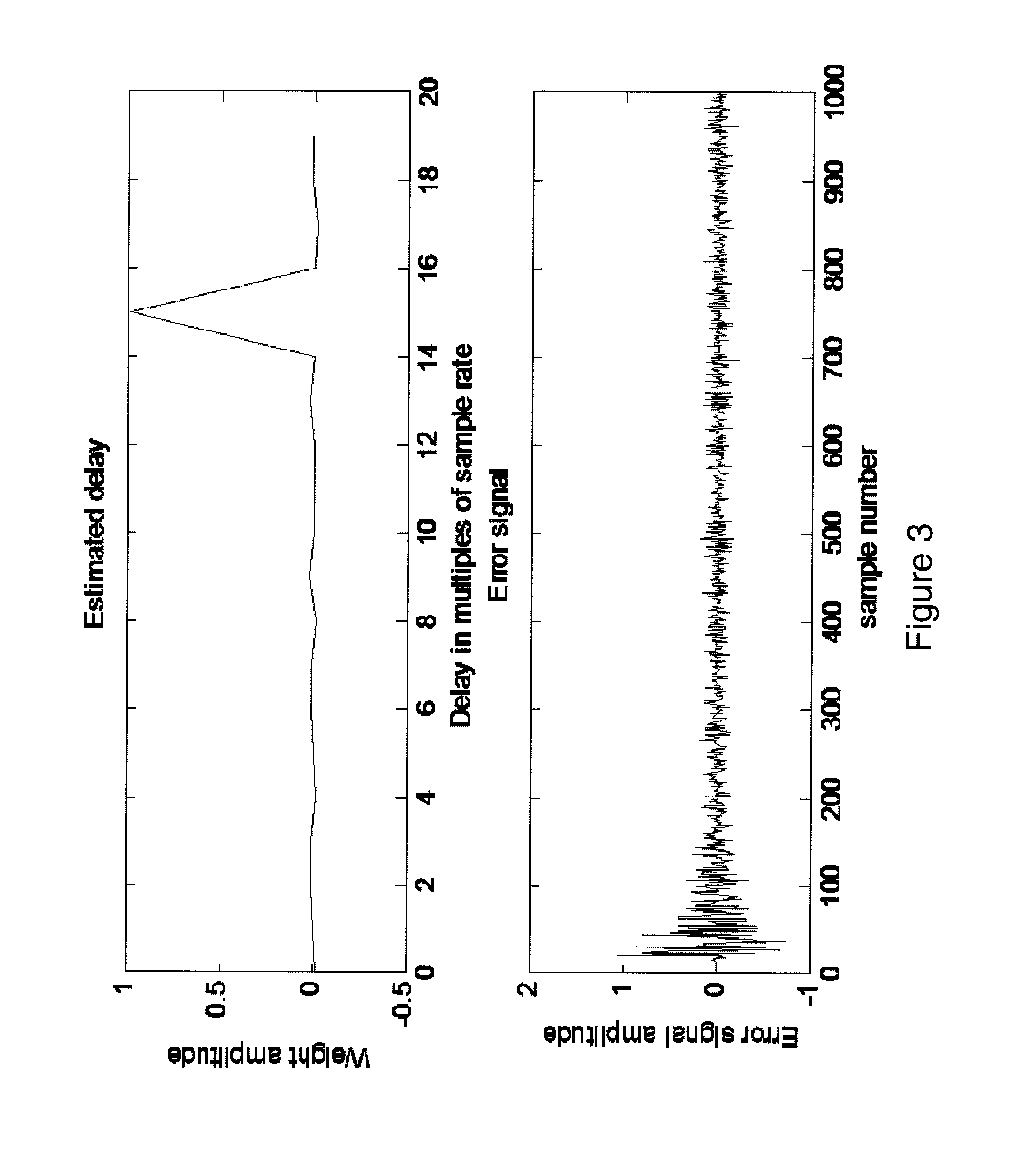
FIG. 3 shows a calculated final weight distribution after 1000 cycles (upper graph) and an error signal for the input in FIG. 2. The weights are initially zero.
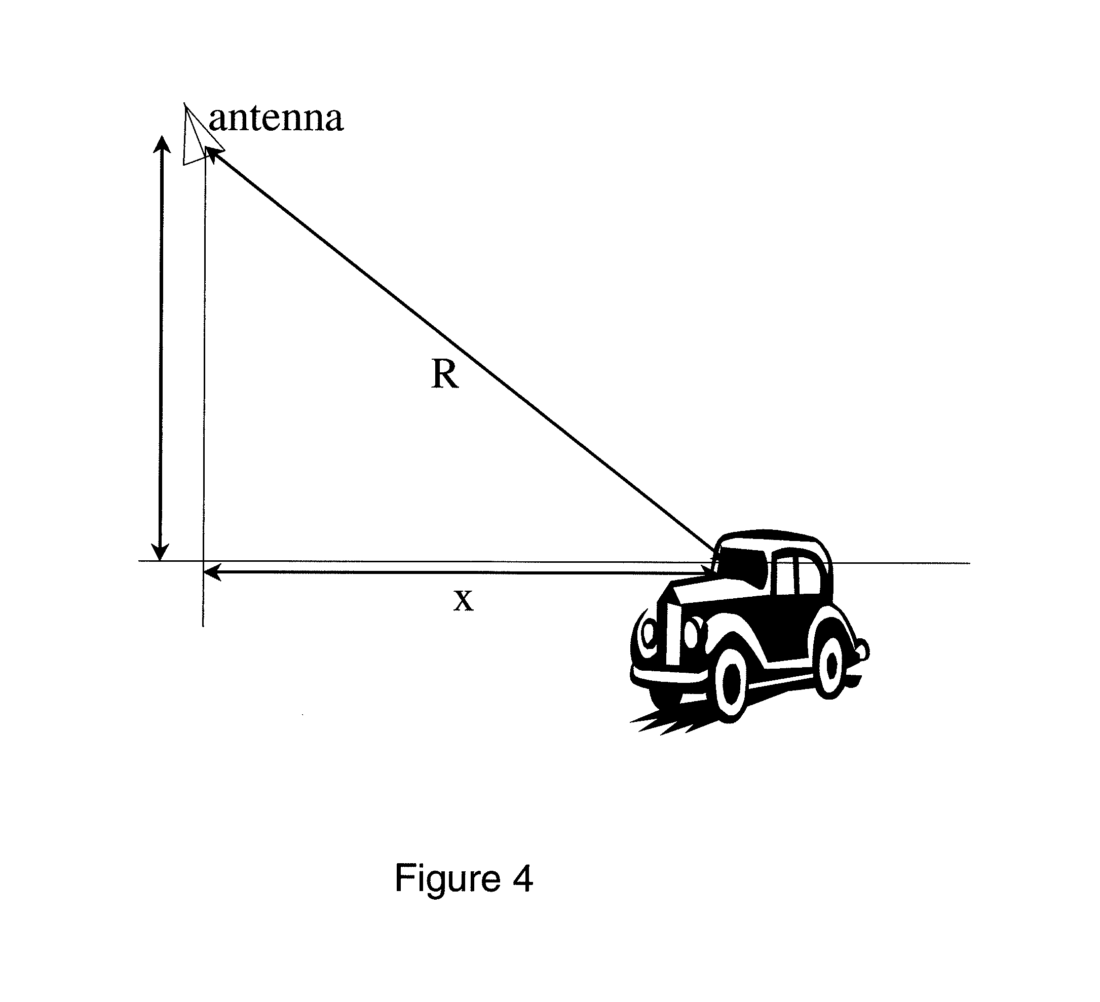
FIG. 4 is a diagram of a toll plaza antenna and a vehicle having an RFID tag.
FIG. 5 is a diagram showing dimensions for a multiple antenna configuration.
DESCRIPTION
The disclosed method is an adaptive linear combiner, which is a tapped delay line with controllable weights on each tap, and outputs that are summed and subtracted from a reference to produce an error signal. While there are multiple possible embodiments to control the weights based on the error signal, a least mean square (LMS) is described here. After a sufficient number of cycles, the weight distribution indicates the delay of the received signal with respect to the reference, and by extension determines the distance between the tag and receiver.
The invention composes an accurate method of identifying the physical location of a vehicle as it passes through an RFID-based tolling zone. One problem of RFID-based toll systems is occasional reads from lanes displaced laterally from the nominal lane beneath an antenna; these are termed cross-lane reads. The cross lane reads are typically handled in the computer that controls the readers by relatively complicated methods. This method, because of its embodiment in the reader, immediately discards cross lane reads because of their large range to the target compared to the range for cars in the proper lane. Another useful aspect of the invention is another method of measuring vehicle speed. While speed can be measured in other ways, this approach allows for range and speed to be measured simultaneously.
In an embodiment of the invention, there is a system in an RFID backscatter tag reader for determining distance from an antenna to a backscatter RFID tag. The system includes: a transmitter for transmitting a transmitted modulated signal to the tag; a receiver for receiving a delayed modulated backscattered signal from the tag; and a linear adaptive combiner which is a tapped delay line with controllable weights on each tap, and outputs that are summed and subtracted from a reference to produce an error signal. Modulation in the backscattered signal is input to the adaptive linear combiner, and the transmitted modulated signal is the reference to the combiner and weights for the taps of the linear adaptive combiner are approximately zero for all of the taps except for the tap corresponding to the delay of the backscattered signal and wherein the distance is determined from the delay. In a further embodiment, the linear adaptive combiner has a sample rate and the system operates at a plurality of sample rates for each distance determination and an optimum distance is determined from the plurality of results.
In a further embodiment, there is a method for determining distance between an RFID backscatter tag and a first antenna. The method includes the steps of: transmitting a modulated signal to the tag through the first antenna; receiving through the first antenna a modulated backscattered signal from the tag; inputting the modulated backscattered signal to an adaptive linear combiner having taps, the taps having weights; applying the modulated signal to the adaptive linear combiner as a reference signal; determining a first signal delay time by which of the taps has the lowest weight; and calculating distance between the tag and the first antenna from the first signal delay time. In a further embodiment of the method a difference in height between the first antenna and the tag is estimated. In a further embodiment of the method, all of the steps are performed with a second antenna located at the same height as the first antenna and a second adaptive linear combiner to produce a second signal delay time, wherein the distance between the first and second antennas is known and wherein the first and second signal delay times are compared to determine a difference in height between the antennas and the tag.
FIG. 1 is a block diagram of the system under consideration. The index k indicates the dimension of time. FIG. 1 shows an adaptive linear combiner, transversal filter format. The weights are updated at each time step as follows:
.mu..times..times..times..times..mu..times..times..times..times..times..t- imes..times. ##EQU00001## .mu..times..times..times. ##EQU00001.2##
This is the LMS algorithm. The parameter .mu. is a scalar gain coefficient. Each weight is adjusted at every time step according to the previous weight and previous input data, system error, and gain coefficient.
In an embodiment, the reader's transmitted CW energy is modulated during the uplink with a known pattern that will be recovered in the backscattered signal. The modulation in the backscattered signal becomes the input X.sub.k to the adaptive linear combiner, while the transmitted signal is the reference. The proper pattern of weights is a value of approximately zero for all but the one corresponding to the delay of the backscattered signal.
The sample rate of the A/D converter is an important quantity affecting the resolution of the proposed technique. The filter operates on samples that are one time step apart, so the final distribution of weights has the same granularity. This implies that the base resolution of the system is no better than the inverse of the sample rate. For a sample rate of 700 MHz, for example, the sample time is 1.42 nsec. Using a free space signal propagation speed of 1 foot/nsec, this corresponds to a physical delay of 1.42 feet. This delay corresponds to the (round trip) total range between the tag and receiver. The height of the receiver antenna requires a translation of this range to the horizontal range, which is the parameter of interest. Deviations of a foot in the total range can imply several feet in the horizontal range.
Basic Adaptive Filter
Reference and backscattered signals are shown in FIG. 2. The sampling rate is 1 GHz. FIG. 2 shows a reference signal in the upper graph and in the lower graph a backscattered signal, containing a small amount of noise, and lagging by 15 samples or 15 nsec.
FIG. 3 shows calculated final weight distribution, after 1000 cycles, and error signal for the input in FIG. 2. The weights are initially zero.
All weights are approximately zero except for the one representing a delay of 15 samples. Note that when the true delay is not equal to an integral number of clock cycles, the resulting weight distribution is still primarily concentrated on a single integer, depending on interference levels. The algorithm produces a delay that effectively rounds the true delay to the nearest N seconds, where N is the time between samples.
Complications from Reader Antenna Height
The height of a typical reader antenna in a toll plaza (typically 18 feet) adds a complication to the problem, summarized in FIG. 4 and Table 1. FIG. 4 shows typical scenario dimensions as tabulated in Table 1, with range to tags for .DELTA.h=13 feet.
TABLE-US-00001 TABLE 1 Horizontal Distance to tag distance to tag Distance to tag in adjacent lane (x, feet) (R, feet) (feet) 0 13 17.69 1 13.04 17.72 2 13.15 17.80 3 13.34 17.94 4 13.60 18.14 5 13.92 18.38 6 14.32 18.68 7 14.76 19.03 8 15.26 19.42 9 15.81 19.85 10 16.40 20.32 11 17.03 20.83 12 17.69 21.38
Therefore, a resolving the range to approximately a tenth of a foot is required to determine horizontal positions of a tag to within a foot. This is an order of magnitude less than the 1.42 feet limit on the range imposed by the sampling rate. The tags that are one lane away (12 feet) have ranges that are only about 4 feet greater for the same horizontal distance.
The adaptive filter can only resolve distances that are one `sample` apart. However, utilizing different sampling rates will produce different range estimates. In general, changing the sampling rate in real time, producing one range estimate per sample rate, and choosing the maximum range estimate can theoretically achieve the required resolution.
For example, if .DELTA.h is 13 feet, and actual true horizontal distance is 10 feet. The table below summarizes the estimated horizontal distances for 10 different clock rates. The noise and interference are negligible. Table 2 shows estimated distances for .DELTA.h=13 feet and x=10 feet, as a function of sample time. Note that the total range is 2*R.sub.est, and is equal to an integer multiple of the sample time.
TABLE-US-00002 TABLE 2 Sample time (nsec) Clock rate (MHz) R.sub.est (feet) X.sub.est (feet) 1.428 700 15.7 1.449 690 15.94 9.2 1.47 680 16.17 9.6 1.492 670 15.66 8.7 1.513 660 15.89 9.1 1.535 651 16.11 9.5 1.556 643 16.34 1.577 634 15.77 8.9 1.599 625 15.99 9.3 1.62 617 16.2 9.7
The best and worst results in the fourth column are highlighted. The spread between best and worst results, highlighted in Table 2, is about 1 foot. However, as the horizontal distance is reduced, the spread increases, as seen in the next example with the same parameters as the previous example, except the horizontal distance is 4.1 feet.
TABLE-US-00003 TABLE 3 Sample time (nsec) Clock rate (MHz) R.sub.est (feet) X.sub.est (feet) 1.428 700 13.56 3.9 1.449 690 13.04 1.0 1.47 680 13.23 2.5 1.492 670 13.43 3.4 1.513 660 13.62 1.535 651 13.04 1.0 1.556 643 13.22 2.4 1.577 634 13.41 3.3 1.599 625 13.59 4.0 1.62 617 12.96
Not only is the spread between best and worst estimates much larger, but the estimate is actually imaginary for one clock rate. This is because the horizontal distance is computed by X.sub.est= {square root over (R.sub.est.sup.2-.DELTA.h.sup.2)}, and the estimated value for R.sub.est is smaller than the value of .DELTA.h. The example underscores the fact that at short horizontal distances, a single estimate (i.e. one clock period) can be off by several feet or not even be a real number.
In general, this technique would require several clock cycle changes during one uplink period, producing several estimates for the range. The maximum value among the estimates is the closest to the true range.
Complications of Variable Tag Height
Additional complication comes from variation in the tag height. In order to estimate the horizontal range (X.sub.est), the value of .DELTA.h must be assumed. If the assumed .DELTA.h is too high, the value for X.sub.est becomes imaginary at short ranges. If it is too low, the value for X.sub.est suffers from low accuracy at short ranges. This is demonstrated in Table 4, which shows. Estimated horizontal distances with an assumed .DELTA.h of 13' where actual .DELTA.h values vary per column.
TABLE-US-00004 TABLE 4 X.sub.est (feet) for true X.sub.est (feet) for true X.sub.est (feet) for true X (feet) .DELTA.h = 12' .DELTA.h = 13' .DELTA.h = 14' 10 8.6 9.9 11.2 9 7.5 9.0 10.4 8 6.2 8.0 9.5 7 4.8 6.9 8.7 6 3.3 6.0 7.8 5 0 5.0 7.2 4 4.0 6.5 3 2.9 6.0 2 2.0 5.5 1 0.8 5.3
If the assumed .DELTA.h is near the true .DELTA.h, the error is small. The error is as high as 5' for the other cases, and imaginary ranges result if the assumed .DELTA.h is too high.
There are at least 2 ways to deal with this problem. The simplest and least accurate is to adjust the tag height assumption in real time when an imaginary range is computed. Another method is to add a second antenna and receiver, using the known separation between the antennas to determine a better assumption for .DELTA.h and therefore a more accurate horizontal distance estimate.
Method 1: Adjustment of Assumed Height
The simplest but least accurate approach is to begin the estimate process with an assumption for .DELTA.h that represents an average value. Then it is reduced as needed, when the resulting horizontal range estimate becomes imaginary. Consider the second column in Table 4, where the assumed .DELTA.h is 13' and the true .DELTA.h is 12'. The error at a 10' range is 1.4' and increases as the tag moves closer to the antenna, reaching 5' when the tag is 5' away. At closer distances, the estimated range is imaginary with an assumed .DELTA.h of 13', but if the assumed .DELTA.h is reduced to 12', the error will be less than 1'. There may be more sophisticated methods of adjusting the assumed .DELTA.h that result in increased accuracy.
Altering the assumed .DELTA.h does not require re-running the adaptive filter through an additional cycle. The filter specifically computes the range R, not the horizontal range. The imaginary number results from the single calculation X.sub.est= {square root over (R.sub.est.sup.2-.DELTA.h.sup.2)}, and altering the assumed .DELTA.h and re-calculating can be done without re-estimating X.
Method 2: Multiple Antennas
For a given assumed height .DELTA.h, the estimated horizontal ranges are: X.sub.1est= {square root over (R.sub.1est.sup.2-.DELTA.h.sup.2)} and X.sub.2est= {square root over (R.sub.2est.sup.2-.DELTA.h.sup.2)}.
and the difference between the two, X.sub.1est-X.sub.2est= {square root over (R.sub.1est-.DELTA.h)}- {square root over (R.sub.2est-.DELTA.h)},
can be compared to the known quantity X.sub.1-X.sub.2.
If the estimated difference is greater/less than the true difference, the assumed .DELTA.h must be reduced/increased. This is repeated until estimated and true values of X.sub.1-X.sub.2 are within an acceptable tolerance. This method requires an additional antenna and processing bank. The potential for imaginary ranges is still present, and would require reducing the assumed value of .DELTA.h, as in the case of a single antenna.
The foregoing description and drawings should be considered as illustrative only of the principles of the invention. The invention may be configured in a variety of ways and is not intended to be limited by the preferred embodiment. Numerous applications of the invention will readily occur to those skilled in the art. Therefore, it is not desired to limit the invention to the specific examples disclosed or the exact construction and operation shown and described. Rather, all suitable modifications and equivalents may be resorted to, falling within the scope of the invention.
* * * * *
D00000
D00001
D00002
D00003
D00004
D00005
M00001
P00001
P00002
P00003
P00004
P00005
P00006

P00007

P00008

XML
uspto.report is an independent third-party trademark research tool that is not affiliated, endorsed, or sponsored by the United States Patent and Trademark Office (USPTO) or any other governmental organization. The information provided by uspto.report is based on publicly available data at the time of writing and is intended for informational purposes only.
While we strive to provide accurate and up-to-date information, we do not guarantee the accuracy, completeness, reliability, or suitability of the information displayed on this site. The use of this site is at your own risk. Any reliance you place on such information is therefore strictly at your own risk.
All official trademark data, including owner information, should be verified by visiting the official USPTO website at www.uspto.gov. This site is not intended to replace professional legal advice and should not be used as a substitute for consulting with a legal professional who is knowledgeable about trademark law.