Mounting and aligning a vehicle side door motor within the current bill of process
Azzouz , et al.
U.S. patent number 10,301,863 [Application Number 14/853,732] was granted by the patent office on 2019-05-28 for mounting and aligning a vehicle side door motor within the current bill of process. This patent grant is currently assigned to Ford Global Technologies, LLC. The grantee listed for this patent is FORD GLOBAL TECHNOLOGIES, LLC. Invention is credited to Michael M. Azzouz, Larry Dean Elie, Gerald J. Heath, John Wayne Jaranson, Timothy J. Potter, Jeffrey A. Wallace.
| United States Patent | 10,301,863 |
| Azzouz , et al. | May 28, 2019 |
Mounting and aligning a vehicle side door motor within the current bill of process
Abstract
A mounting assembly for a vehicle side door motor includes an upper hinge element configured for receiving a side door motor drive shaft and a motor mounting bracket configured to receive the side door motor drive shaft and to allow a radial adjustment of the drive shaft for alignment of an axis of the motor with a side door hinge axis. The upper hinge element may define a clevis including a lower clevis portion having a motor drive shaft mounting aperture dimensioned to allow the radial adjustment feature. The motor mounting bracket includes one or more mounting apertures dimensioned to allow a vehicle fore/aft adjustment and in/out adjustment of the side door motor element. The motor mounting assembly is further configured to allow a vehicle up/down adjustment of the side door motor.
| Inventors: | Azzouz; Michael M. (Livonia, MI), Elie; Larry Dean (Ypsilanti, MI), Jaranson; John Wayne (Dearborn, MI), Wallace; Jeffrey A. (Walled Lake, MI), Potter; Timothy J. (Dearborn, MI), Heath; Gerald J. (Allen Park, MI) | ||||||||||
|---|---|---|---|---|---|---|---|---|---|---|---|
| Applicant: |
|
||||||||||
| Assignee: | Ford Global Technologies, LLC
(Dearborn, MI) |
||||||||||
| Family ID: | 57629815 | ||||||||||
| Appl. No.: | 14/853,732 | ||||||||||
| Filed: | September 14, 2015 |
Prior Publication Data
| Document Identifier | Publication Date | |
|---|---|---|
| US 20170074020 A1 | Mar 16, 2017 | |
| Current U.S. Class: | 1/1 |
| Current CPC Class: | F16M 1/04 (20130101); E05F 15/611 (20150115); E05F 15/614 (20150115); B60J 5/0468 (20130101); B62D 65/024 (20130101); E05F 5/00 (20130101); E05Y 2600/56 (20130101); E05Y 2900/531 (20130101) |
| Current International Class: | B60J 5/04 (20060101); E05F 15/611 (20150101); E05F 15/614 (20150101); B62D 65/02 (20060101); F16M 1/04 (20060101); E05F 5/00 (20170101) |
| Field of Search: | ;296/146.4,146,11,146.8,56,76 ;49/349,350,340 ;16/355,367 |
References Cited [Referenced By]
U.S. Patent Documents
| 2721353 | October 1955 | Mackintosh |
| 2915777 | December 1959 | Allen |
| 3344554 | October 1967 | Misaka et al. |
| 3357137 | December 1967 | Lombardi et al. |
| 3895281 | July 1975 | Corbaz |
| 4078770 | March 1978 | Yates et al. |
| 4121382 | October 1978 | Dietrich |
| 4143497 | March 1979 | Offenbacher |
| 4386398 | May 1983 | Matsuoka et al. |
| 4441376 | April 1984 | Tobey |
| 4488753 | December 1984 | Koike |
| 4497137 | February 1985 | Nelson |
| 4501012 | February 1985 | Kishi et al. |
| 4501090 | February 1985 | Yoshida et al. |
| 4674230 | June 1987 | Takeo et al. |
| 4727679 | March 1988 | Kornbrekke et al. |
| 4763111 | August 1988 | Matsuo et al. |
| 4899945 | February 1990 | Jones |
| 4952080 | August 1990 | Boiucaner et al. |
| 5236234 | August 1993 | Norman |
| 5317835 | June 1994 | Dupuy et al. |
| 5355628 | October 1994 | Dranchak |
| 5369911 | December 1994 | Fortunato |
| 5396158 | March 1995 | Long et al. |
| 5434487 | July 1995 | Long et al. |
| 5787636 | August 1998 | Buchanan, Jr. |
| 5801340 | September 1998 | Peter |
| 5913763 | June 1999 | Beran et al. |
| 6065185 | May 2000 | Breed et al. |
| 6145354 | November 2000 | Kondo et al. |
| 6149222 | November 2000 | Schambre |
| 6247271 | June 2001 | Fioritto et al. |
| 6275231 | August 2001 | Obradovich |
| 6305737 | October 2001 | Corder et al. |
| 6341807 | January 2002 | Cetnar et al. |
| 6370732 | April 2002 | Yezersky et al. |
| 6401392 | June 2002 | Yuge |
| 6435575 | August 2002 | Pajak et al. |
| 6442902 | September 2002 | Van Den Oord |
| 6498970 | December 2002 | Colmenarez et al. |
| 6624605 | September 2003 | Powder et al. |
| 6777958 | August 2004 | Haag et al. |
| 6928694 | August 2005 | Breed et al. |
| 6942277 | September 2005 | Rangnekar |
| 7034682 | April 2006 | Beggs et al. |
| 7045764 | May 2006 | Beggs et al. |
| 7068146 | June 2006 | Sasaki et al. |
| 7104589 | September 2006 | Takeda |
| 7132642 | November 2006 | Shank et al. |
| 7175227 | February 2007 | Menard |
| 7193509 | March 2007 | Bartels et al. |
| 7215529 | May 2007 | Rosenau |
| 7273207 | September 2007 | Studer |
| 7280035 | October 2007 | McLain et al. |
| 7320497 | January 2008 | Zinn et al. |
| 7342373 | March 2008 | Newman et al. |
| 7377557 | May 2008 | Shelley et al. |
| 7400153 | July 2008 | Shoji et al. |
| 7438346 | October 2008 | Breed |
| 7439632 | October 2008 | Ogino et al. |
| 7538506 | May 2009 | Zinn et al. |
| 7540554 | June 2009 | Bals |
| 7566087 | July 2009 | Hanna et al. |
| 7686378 | March 2010 | Gisler et al. |
| 7688179 | March 2010 | Kurpinski et al. |
| 7874609 | January 2011 | Whinnery |
| 7886409 | February 2011 | Yip |
| 7895712 | March 2011 | Krumbiegel et al. |
| 8007027 | August 2011 | Watanabe et al. |
| 8077022 | December 2011 | Baruco et al. |
| 8132844 | March 2012 | Sonnek et al. |
| 8159231 | April 2012 | Sakamaki |
| 8169317 | May 2012 | Lemerand et al. |
| 8186013 | May 2012 | Yip |
| 8237544 | August 2012 | Nakashima |
| 8284022 | October 2012 | Kachouh |
| 8397581 | March 2013 | Ruby, III et al. |
| 8511739 | August 2013 | Brown et al. |
| 8615927 | December 2013 | Ezzat et al. |
| 8641125 | February 2014 | Jimenez et al. |
| 8651461 | February 2014 | Christensen et al. |
| 2001/0004164 | June 2001 | Mattsson |
| 2002/0039008 | April 2002 | Edgar et al. |
| 2003/0038544 | February 2003 | Spurr |
| 2003/0222758 | December 2003 | Willats et al. |
| 2005/0174077 | August 2005 | Haag et al. |
| 2005/0242618 | November 2005 | Menard |
| 2005/0280284 | December 2005 | McLain et al. |
| 2006/0071505 | April 2006 | Ciavaglia |
| 2006/0230574 | October 2006 | Murayama et al. |
| 2007/0090654 | April 2007 | Eaton |
| 2007/0186480 | August 2007 | Freeman |
| 2007/0192038 | August 2007 | Kameyama |
| 2008/0211519 | September 2008 | Kurumado et al. |
| 2008/0295408 | December 2008 | Heissler |
| 2008/0296927 | December 2008 | Gisler et al. |
| 2009/0113797 | May 2009 | Hoermann |
| 2009/0153151 | June 2009 | Cho et al. |
| 2010/0224117 | September 2010 | Christensen et al. |
| 2011/0203181 | August 2011 | Magner et al. |
| 2011/0260848 | October 2011 | Rodriguez Barros et al. |
| 2011/0295469 | December 2011 | Rafii et al. |
| 2012/0042572 | February 2012 | Yuge |
| 2012/0179336 | July 2012 | Oakley |
| 2013/0031747 | February 2013 | Gobart |
| 2013/0074412 | March 2013 | Wellborn |
| 2013/0091768 | April 2013 | Houser et al. |
| 2013/0127479 | May 2013 | Grills et al. |
| 2013/0138303 | May 2013 | McKee et al. |
| 2014/0000165 | January 2014 | Patel et al. |
| 2014/0055349 | February 2014 | Itoh |
| 2014/0130299 | May 2014 | Jaranson |
| 2014/0150581 | June 2014 | Scheuring et al. |
| 2014/0297060 | October 2014 | Schmidt et al. |
| 2014/0373454 | December 2014 | Sasaki |
| 2015/0059250 | March 2015 | Miu |
| 2034320 | Nov 1994 | CA | |||
| 101403271 | Apr 2009 | CN | |||
| 201343938 | Nov 2009 | CN | |||
| 101812952 | Aug 2010 | CN | |||
| 202294674 | Jul 2012 | CN | |||
| 103132847 | Jun 2013 | CN | |||
| 103269914 | Aug 2013 | CN | |||
| 203143980 | Aug 2013 | CN | |||
| 103422764 | Dec 2013 | CN | |||
| 203551964 | Apr 2014 | CN | |||
| 203580775 | May 2014 | CN | |||
| 4119579 | Dec 1992 | DE | |||
| 4207706 | Sep 1993 | DE | |||
| 10004161 | Aug 2001 | DE | |||
| 10038803 | Feb 2002 | DE | |||
| 10261504 | Aug 2004 | DE | |||
| 102008010836 | Sep 2008 | DE | |||
| 102007062473 | Jul 2009 | DE | |||
| 0397300 | Nov 1990 | EP | |||
| 2174814 | Apr 2010 | EP | |||
| 1265772 | Dec 2010 | EP | |||
| 2287430 | Feb 2011 | EP | |||
| 1899565 | Oct 2011 | EP | |||
| 2583848 | Apr 2013 | EP | |||
| 2765112 | Aug 2014 | EP | |||
| 2873074 | Jan 2006 | FR | |||
| 07285789 | Oct 1995 | JP | |||
| 2000080828 | Mar 2000 | JP | |||
| 2000318444 | Nov 2000 | JP | |||
| 2004176426 | Jun 2004 | JP | |||
| 2009161959 | Jul 2009 | JP | |||
| 20100095383 | Apr 2010 | JP | |||
| 2013007171 | Jan 2013 | JP | |||
| 2013028903 | Feb 2013 | JP | |||
| 2014129037 | Jul 2014 | JP | |||
| 2014148842 | Aug 2014 | JP | |||
| 20020048811 | Jun 2002 | KR | |||
| 20130068538 | Jun 2013 | KR | |||
| 20100098620 | Sep 2010 | WO | |||
| 2013013313 | Jan 2013 | WO | |||
| 2013074901 | May 2013 | WO | |||
Other References
|
Steeven Zei , Alexander Marinc, Andreas Braun, Tobias Gro e-Puppendahl, Sebastian Beck; "A Gesture-based Door Control Using Capacitive Sensors"; Fraunhofer-Institut fur Graphische Datenverarbeitung IGD; pp. 1-10; date unknown. cited by applicant . Abd Manan Bin Ahmad; "The Design and Development of a System for Controlling Automotive Functions using Recognition"; Universiti Teknologi Malaysia; pp. 1-100; 2006. Speech. cited by applicant . Haleem, M.S.; "Voice Controlled Automation System"; IEEE International; Dept. of Electron. Eng., NED Univ. of Eng. & Technol.; Multitopic Conference; Print ISBN: 978-1-4244-2823-6; pp. 1-2; Dec. 23-24, 2008. cited by applicant . "InnoTrans 2014: Safety on Vehicle Doors with Non-Touch Detection System from Mayser"; Mayser Safety Technology; pp. 1-1; Aug. 4, 2014. cited by applicant . Bogdan Popa; "How BMW's Soft Close Doors Work"; Autoevolution; pp. 1-6; Aug. 18, 2012. cited by applicant . English machine translation of DE102008010836A1. cited by applicant . English machine translation of DE10261504A1. cited by applicant . English machine translation of CN101812952A. cited by applicant. |
Primary Examiner: Dayoan; D Glenn
Assistant Examiner: Westbrook; Sunsurraye
Attorney, Agent or Firm: Rogers; Jason Chea; Vichit King & Schickli PLLC
Claims
What is claimed:
1. A mounting assembly for a vehicle side door motor, comprising a motor mounting bracket configured to allow a radial adjustment of a side door motor element for alignment of a motor element longitudinal axis with a side door hinge assembly longitudinal axis.
2. The mounting assembly of claim 1, wherein the side door hinge assembly includes an upper hinge element having a lower clevis providing a longitudinal axis reference point for the side door motor element and the side door hinge assembly.
3. The mounting assembly of claim 1, wherein the motor mounting bracket includes one or more mounting apertures dimensioned to allow a vehicle fore/aft adjustment and in/out adjustment of the side door motor element.
4. The mounting assembly of claim 3, wherein the motor mounting bracket is configured to allow a vehicle up/down adjustment of the side door motor element.
5. The mounting assembly of claim 1, further including a side door check element configured for supporting the motor mounting bracket.
6. A vehicle including the assembly of claim 1.
7. A vehicle side door assembly, comprising: a hinged side door; a motor for opening/closing the hinged side door assembly; and a motor mounting bracket configured to allow a radial adjustment of a side door motor element for alignment of a motor element longitudinal axis with a side door hinge assembly longitudinal axis.
8. The side door assembly of claim 7, wherein the side door hinge assembly includes an upper hinge element having a lower clevis providing a longitudinal axis reference point for the side door motor element and the side door hinge assembly.
9. The side door assembly of claim 7, wherein the motor mounting bracket includes one or more mounting apertures dimensioned to allow a vehicle fore/aft adjustment and in/out adjustment of the side door motor element.
10. The side door assembly of claim 9, wherein the motor mounting bracket is configured to allow a vehicle up/down adjustment of the side door motor element.
11. The side door assembly of claim 7, further including a side door check element configured for supporting the motor mounting bracket.
12. A vehicle including the assembly of claim 7.
13. A vehicle, comprising: a body; a side door including a hinge assembly; a motor for opening/closing the hinged side door; and a motor mounting bracket configured to allow a radial adjustment of a side door motor element for alignment of a motor element longitudinal axis with a side door hinge assembly longitudinal axis.
14. The vehicle of claim 13, wherein the side door hinge assembly includes an upper hinge element having a lower clevis providing a longitudinal axis reference point for the side door motor element and the side door hinge assembly.
15. The vehicle of claim 13, wherein the motor mounting bracket includes one or more mounting apertures dimensioned to allow a vehicle fore/aft adjustment and in/out adjustment of the side door motor element.
16. The vehicle of claim 15, wherein the motor mounting bracket is configured to allow a vehicle up/down adjustment of the side door motor.
17. The vehicle of claim 13, further including a side door-mounted door check element configured for supporting the motor mounting bracket.
Description
TECHNICAL FIELD
This disclosure relates generally to vehicle doors, particularly to doors incorporating motor-driven or "smart" door open/close technology.
BACKGROUND
During motor vehicle body shell manufacture and assembly the typical bill of process requires the side doors to be installed on the vehicle body shell and set for alignment to provide appropriate margin and flushness to adjacent body panels. This is achieved by first mounting hinges to the doors, manually or robotically aligning the hinged door assembly to the body shell, and securing the hinges in place. The completed body shell with aligned doors is then cycled through various additional processes, such as corrosion protection, a paint process, and others. After painting, the doors must be removed. This is because during final vehicle assembly access through the door openings is required to install other vehicle components such as the instrument panel, seats and other interior trim. To accomplish this, the doors are removed by removing only the center hinge pin, thus maintaining the alignment for final assembly by way of the respective body and door brackets.
In conventional manufacturing processes, the above-summarized bill of process must be modified for vehicles including side doors incorporating "smart" technology, i.e. motor-driven or assisted opening/closing, door edge protect, power cinch, door open assist, door soft close, and other functions. This is because in a door wherein a motor is mounted to the hinge, the motor assembly must be directly aligned to the hinge axis to provide smooth open/close operation and to reduce or eliminate functional failures. However, the motor mechanism cannot be exposed to certain of the above processes such as corrosion protection, painting, etc., and so cannot be installed until after those processes are completed. Moreover, due to inter-vehicle dimensional variations in door structure, body structure, and hinge assemblies, the hinge axis varies from one vehicle design to another. Thus, the automated process of installing/removing door structures during manufacture/assembly becomes more complicated in vehicles incorporating motor-driven doors, with attendant increases in manufacturing/assembly labor and cost.
To solve these and other problems, the present disclosure describes a side door motor mounting assembly which enables the mounting and proper alignment of a door motor with a door hinge assembly axis. Advantageously, the described mounting assembly includes a radial adjustment feature allowing making adjustments to the motor positioning to ensure direct alignment to the door hinge axis, thus ensuring smooth and proper functioning of the motor-driven door.
SUMMARY
In accordance with the purposes and benefits described herein, in one aspect a door motor mounting assembly is described. The assembly includes a modified vehicle body-mounted upper hinge portion defining a clevis allowing alignment of a side door motor axis to the side door hinge axis. In turn, the assembly includes a motor mounting bracket providing a radial adjustment feature for motor alignment. The motor mounting bracket is supported/reinforced by a door-mounted check bracket. Advantageously, once assembled the motor mounting assembly provides ample clearance for removal of the vehicle doors prior to various processes such as corrosion resistance treatment, painting, etc. alternatively, the described assembly allows accomplishing the described attachment/alignment steps later in the vehicle manufacturing/assembly process, such as in trim and during final assembly.
In another aspect, a method for aligning a door motor in a vehicle door is provided, utilizing the described motor mounting assembly.
In the following description, there are shown and described embodiments of the disclosed side door motor mounting assembly. As it should be realized, the assembly is capable of other, different embodiments and its several details are capable of modification in various, obvious aspects all without departing from the devices and methods as set forth and described in the following claims. Accordingly, the drawings and descriptions should be regarded as illustrative in nature and not as restrictive.
BRIEF DESCRIPTION OF THE DRAWINGS
The accompanying drawing figures incorporated herein and forming a part of the specification, illustrate several aspects of the disclosed side door motor mounting assembly, and together with the description serve to explain certain principles thereof. In the drawings:
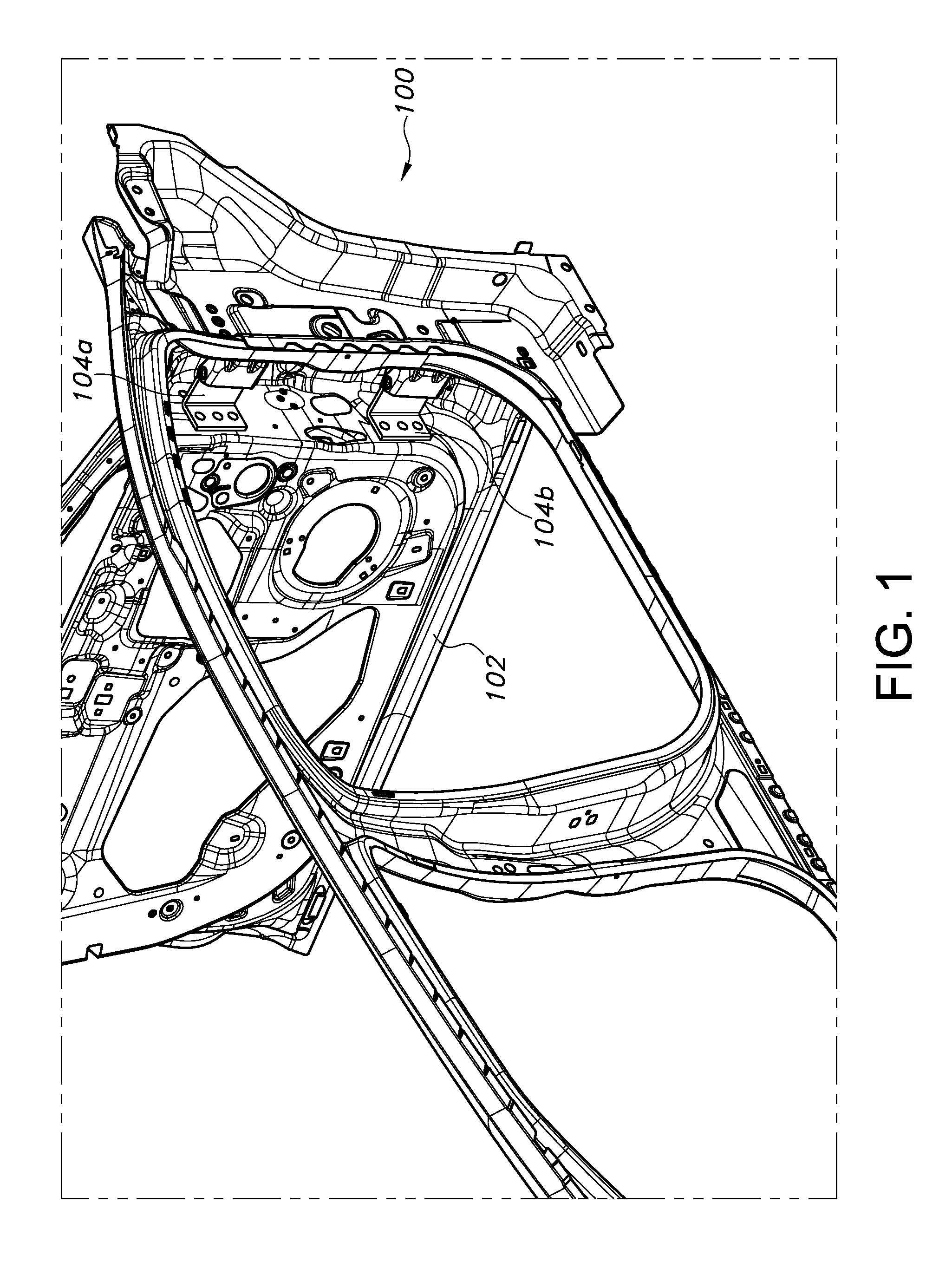
FIG. 1 depicts a side view of a conventional vehicle body/side door assembly;
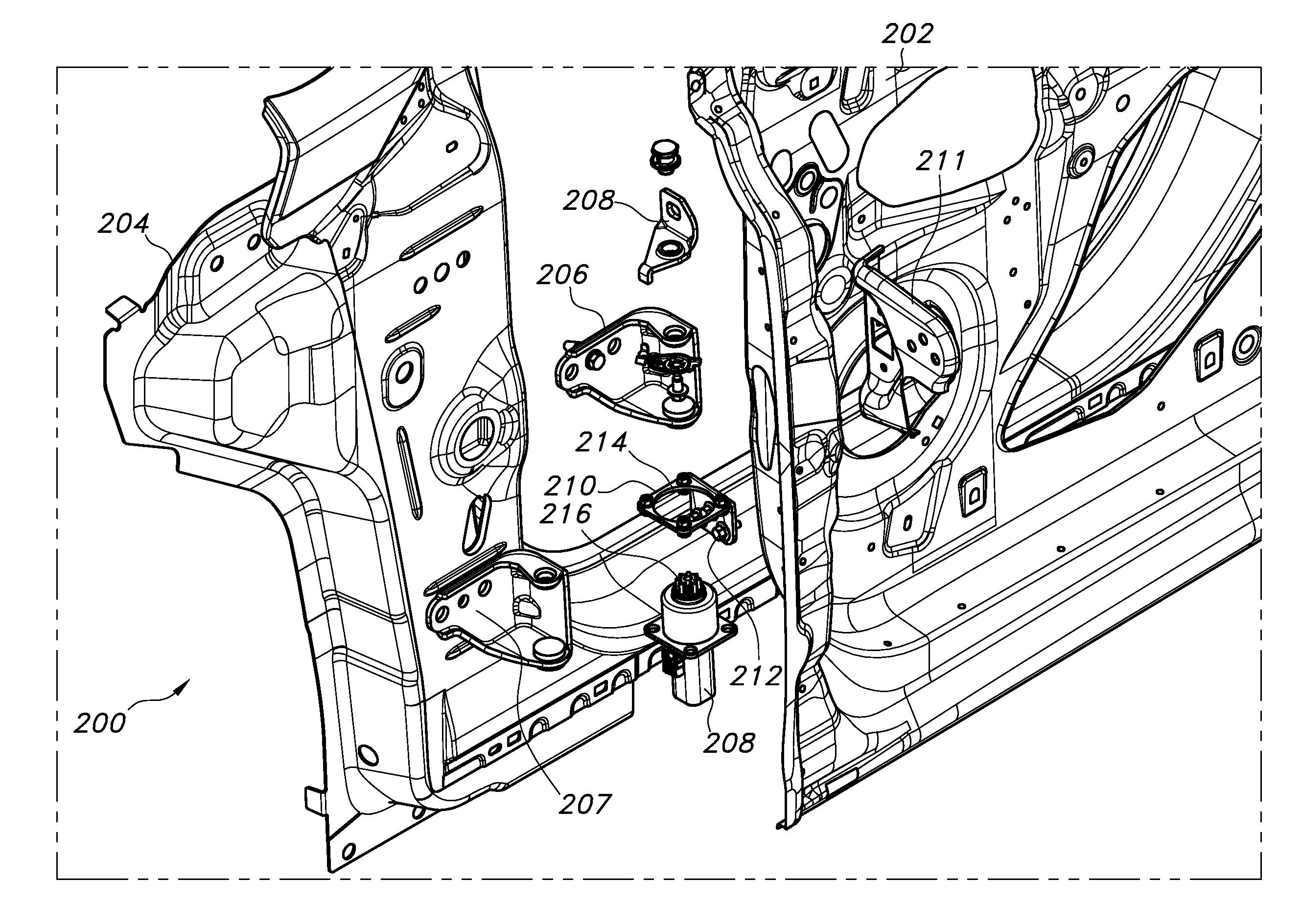
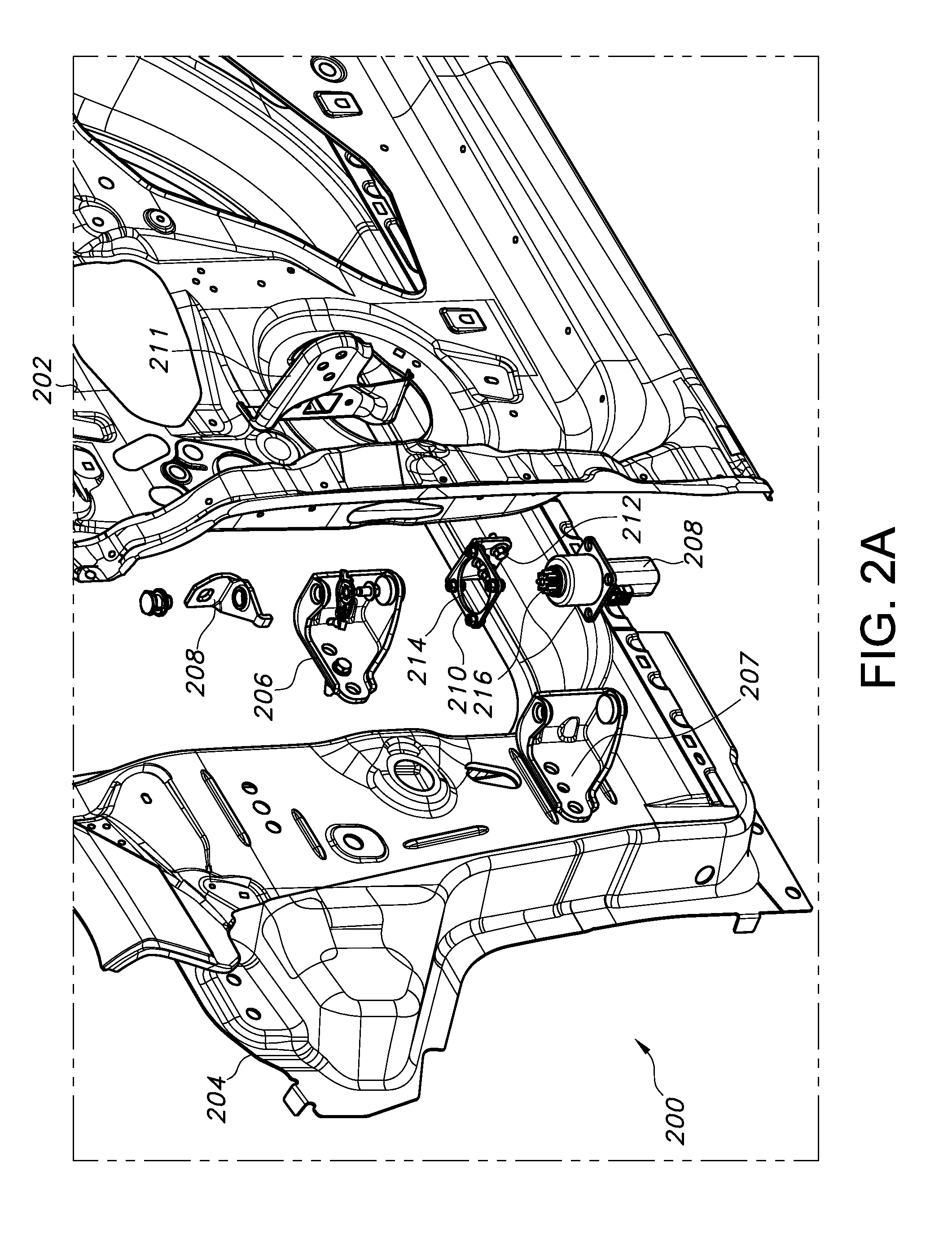
FIG. 2A depicts an exploded side view of a motor-driven side door motor mounting assembly according to the present disclosure;
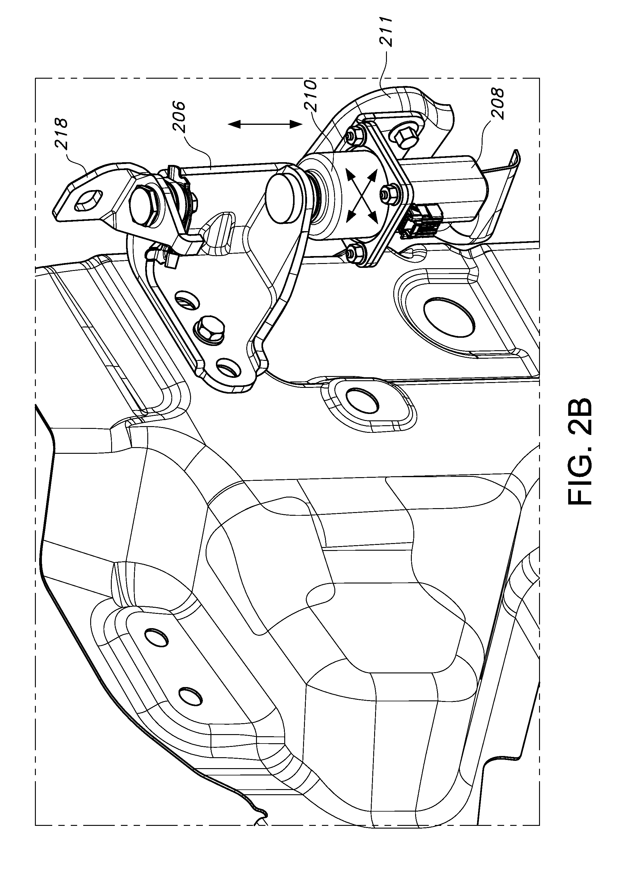
FIG. 2B depicts an isolated view of the assembled side door motor mounting assembly of FIG. 2A;
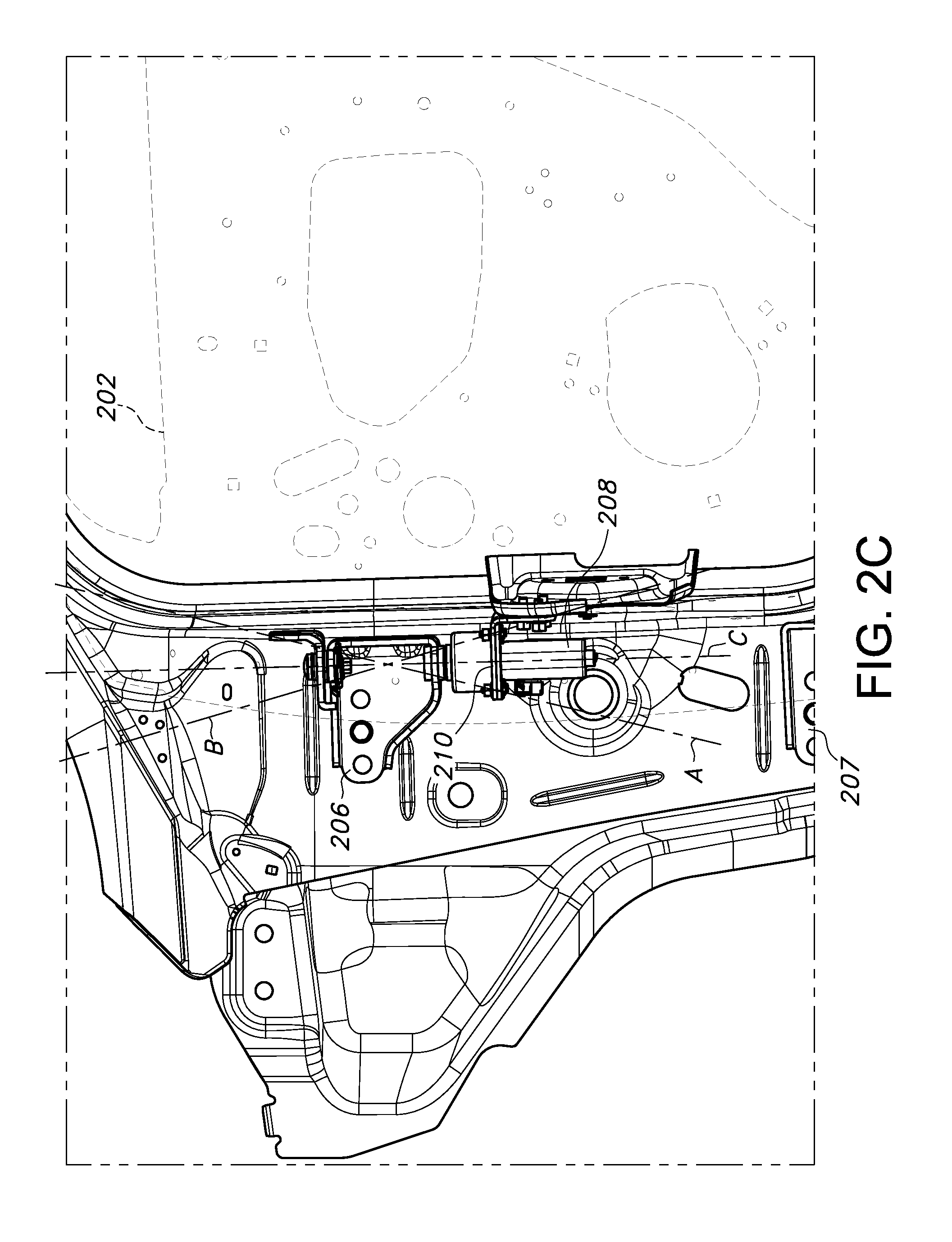
FIG. 2C depicts adjustment of a longitudinal axis of a motor of the side door motor mounting assembly of FIG. 2A; and
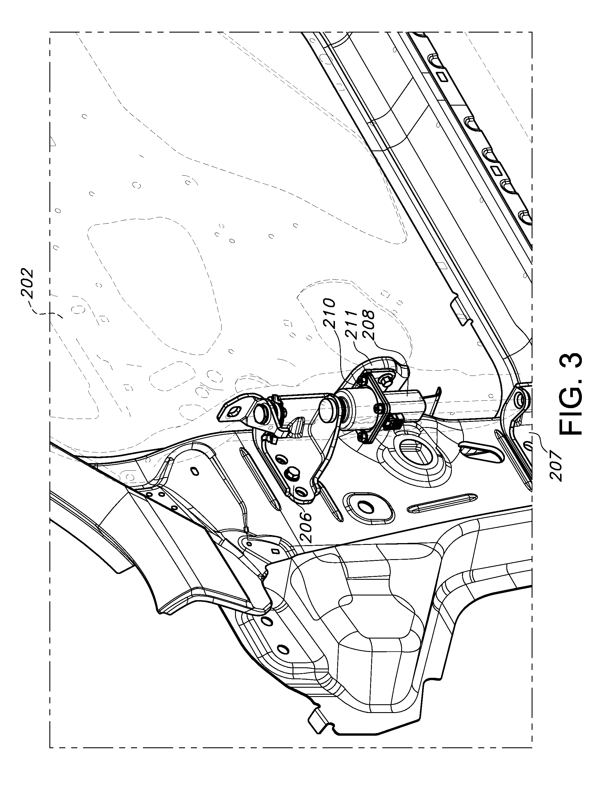
FIG. 3 depicts an assembled vehicle body/motor-driven side door according to the present disclosure.
Reference will now be made in detail to embodiments of the disclosed door motor mounting assembly, examples of which are illustrated in the accompanying drawing figures wherein like reference numerals identify like features.
DETAILED DESCRIPTION
Reference is now made to FIG. 1 schematically illustrating a conventional vehicle 100 side door assembly. At a high level, such assemblies include at least a side door 102 and one or more vehicle body-mounted hinge assemblies 104, in the depicted embodiment being an upper hinge assembly 104a and a lower hinge assembly 104b. Of course, the vehicle side door 102 depicted in the drawing figure is greatly simplified for purposes of illustration, as a modern vehicle side door can be quite complex and can include many features in addition to those depicted in the drawing. As discussed above, for a motor-driven vehicle side door 102, the motor (not shown in this view) cannot be passed through certain processes, such as corrosion protection, painting, etc. Instead, the typical procedure is to install or re-install the motor in trim or during final assembly, after the above processes are completed.
However, as is also discussed above, it is important to properly align the motor to ensure proper opening/closing of the side door. Specifically, at final vehicle assembly it is important to align a longitudinal axis of the side door motor with a longitudinal axis defined by the vehicle side door hinge assembly. To solve this and other problems, with reference to FIG. 2A there is depicted a vehicle side door assembly 200. The assembly 200 includes at least a side door 202 which is hingedly attached to a vehicle body 204 by a hinge assembly, in the depicted embodiment including an upper hinge element 206 and a lower hinge element 207. A motor 208 is included to drive automatic or manually initiated opening/closing of the side door 202. Such motors are well known in the art, and do not require extensive discussion or description herein.
The assembly 200 further includes a motor mounting bracket 210 configured for attachment to a door-mounted check element 211. The motor mounting bracket 210, which in the depicted embodiment substantially defines an L shape, includes a plurality of mounting apertures 212, each of which is dimensioned to allow a radial slip of the motor 208 for alignment of a longitudinal axis of the motor with a longitudinal axis of the hinge assembly. The motor mounting bracket 210 further includes a drive shaft aperture 214 for receiving a drive shaft 216 of the motor 208, also dimensioned to allow a radial slip of the motor 208. Additional door-mounted support brackets 218 may be provided.
With reference to FIG. 2B, the motor 208, body-mounted upper hinge 206, motor mounting bracket 210, and door check element 211 are shown in an assembled configuration. By the dimensions of motor mounting bracket apertures 212, 214, as shown by the arrows a vehicle fore/aft, in/out, and up/down adjustment or slip is made possible, allowing alignment of the motor 208 longitudinal axis (broken lines A, B) with a longitudinal axis defined by the hinge assembly 206, 207. This is shown in greater detail in FIG. 2C.
Thus, at final assembly of the vehicle body 204 and side door 202 (see FIG. 3), a properly aligned motor 208 can be provided, ensuring a smooth and reliable opening/closing of the side door 202. As a further advantage, best as shown in FIG. 2B by use of the described upper hinge 206, ample clearance is provided for removal of fasteners during the process of removal of the vehicle door 202 and motor 208 prior to processes such as corrosion protection, painting, etc.
Obvious modifications and variations are possible in light of the above teachings. All such modifications and variations are within the scope of the appended claims when interpreted in accordance with the breadth to which they are fairly, legally and equitably entitled.
* * * * *
D00000
D00001
D00002
D00003
D00004
D00005
XML
uspto.report is an independent third-party trademark research tool that is not affiliated, endorsed, or sponsored by the United States Patent and Trademark Office (USPTO) or any other governmental organization. The information provided by uspto.report is based on publicly available data at the time of writing and is intended for informational purposes only.
While we strive to provide accurate and up-to-date information, we do not guarantee the accuracy, completeness, reliability, or suitability of the information displayed on this site. The use of this site is at your own risk. Any reliance you place on such information is therefore strictly at your own risk.
All official trademark data, including owner information, should be verified by visiting the official USPTO website at www.uspto.gov. This site is not intended to replace professional legal advice and should not be used as a substitute for consulting with a legal professional who is knowledgeable about trademark law.