Floorboards provided with a mechanical locking system
Boo
U.S. patent number 10,301,830 [Application Number 14/224,628] was granted by the patent office on 2019-05-28 for floorboards provided with a mechanical locking system. This patent grant is currently assigned to VALINGE INNOVATION AB. The grantee listed for this patent is Valinge Innovation AB. Invention is credited to Christian Boo.

| United States Patent | 10,301,830 |
| Boo | May 28, 2019 |
Floorboards provided with a mechanical locking system
Abstract
Floorboards provided with a mechanical locking system including a locking strip protruding from a first edge of a first floorboard. The locking strip is provided with a locking element configured to cooperate with a locking groove at a lower side of a second edge of a second floorboard for locking the first edge and the second edge in a horizontal direction. The first edge and the second edge are configured to be assembled by a vertical downward motion of the second edge towards the first edge. The second edge is provided with a calibrating groove adjacent the locking groove. The disclosure also relates to a method for producing a mechanical locking system.
| Inventors: | Boo; Christian (Kagerod, SE) | ||||||||||
|---|---|---|---|---|---|---|---|---|---|---|---|
| Applicant: |
|
||||||||||
| Assignee: | VALINGE INNOVATION AB (Viken,
SE) |
||||||||||
| Family ID: | 51568106 | ||||||||||
| Appl. No.: | 14/224,628 | ||||||||||
| Filed: | March 25, 2014 |
Prior Publication Data
| Document Identifier | Publication Date | |
|---|---|---|
| US 20140283466 A1 | Sep 25, 2014 | |
Foreign Application Priority Data
| Mar 25, 2013 [SE] | 1350377-6 | |||
| Current U.S. Class: | 1/1 |
| Current CPC Class: | E04F 15/107 (20130101); E04F 15/02038 (20130101); E04F 2201/042 (20130101); E04F 2201/0146 (20130101); E04F 2201/0547 (20130101); E04F 2203/08 (20130101) |
| Current International Class: | E04F 15/02 (20060101); E04F 15/10 (20060101) |
| Field of Search: | ;52/588.1,592.1,592.2,390,392,533,534,539,553,582.1,586.1,586.2,590.2,590.3,591.1,591.2,591.3,571.4,591.5,592.4,745.09,745.19,747.1,747.11,748.1,748.11,598.1 ;403/372,375,376,381 |
References Cited [Referenced By]
U.S. Patent Documents
| 213740 | April 1879 | Connor |
| 1394120 | October 1921 | Rockwell |
| 1787027 | December 1930 | Wasleff |
| 1925070 | August 1933 | Livezey |
| 2015813 | October 1935 | Nielsen |
| 2088238 | July 1937 | Greenway |
| 2089075 | August 1937 | Siebs |
| 2266464 | December 1941 | Kraft |
| 2303745 | December 1942 | Karreman |
| 2306295 | December 1942 | Casto |
| 2497837 | February 1950 | Nelson |
| 2740167 | April 1956 | Rowley |
| 2769726 | November 1956 | Wetterau et al. |
| 2818895 | January 1958 | Zuber |
| 2872712 | February 1959 | Brown |
| 2947040 | August 1960 | Schultz |
| 3055461 | September 1962 | De Ridder |
| 3087269 | April 1963 | Hudson |
| 3120083 | February 1964 | Dahlberg et al. |
| 3247638 | April 1966 | Gay et al. |
| 3259417 | July 1966 | Chapman |
| 3397496 | August 1968 | Sohns |
| 3436888 | April 1969 | Ottosson |
| 3538665 | November 1970 | Gohner |
| 3554850 | January 1971 | Kuhle |
| 3578548 | May 1971 | Wesp |
| 3694983 | October 1972 | Couquet |
| 3720027 | March 1973 | Christensen |
| 3742669 | July 1973 | Mansfeld |
| 3760547 | September 1973 | Brenneman |
| 3857749 | December 1974 | Yoshida |
| 3919820 | November 1975 | Green |
| 3937861 | February 1976 | Zuckerman et al. |
| 4037377 | July 1977 | Howell et al. |
| 4100710 | July 1978 | Kowallik |
| 4113399 | September 1978 | Hansen, Sr. et al. |
| 4172169 | October 1979 | Mawson et al. |
| 4176210 | November 1979 | Skinner |
| 4180615 | December 1979 | Bettoli |
| 4187131 | February 1980 | Shortway et al. |
| 4196554 | April 1980 | Anderson et al. |
| 4242390 | December 1980 | Nemeth |
| 4299070 | November 1981 | Oltmanns et al. |
| 4313866 | February 1982 | Renshaw |
| 4333987 | June 1982 | Kwart et al. |
| 4393187 | July 1983 | Boba et al. |
| 4423178 | December 1983 | Renshaw |
| 4426820 | January 1984 | Terbrack et al. |
| 4489115 | December 1984 | Layman et al. |
| 4507188 | March 1985 | Chu |
| 4512131 | April 1985 | Laramore |
| 4570353 | February 1986 | Evans |
| 4574099 | March 1986 | Nixon |
| 4599841 | July 1986 | Haid |
| 4614680 | September 1986 | Fry et al. |
| 4772500 | September 1988 | Stroppiana |
| 4785065 | November 1988 | Uhl et al. |
| 4807412 | February 1989 | Frederiksen |
| 4944514 | July 1990 | Suiter |
| 5007222 | April 1991 | Raymond |
| 5050362 | September 1991 | Tal et al. |
| 5112671 | May 1992 | Diamond et al. |
| 5134026 | July 1992 | Melcher |
| 5148850 | September 1992 | Urbanick |
| 5162141 | November 1992 | Davey et al. |
| 5182892 | February 1993 | Chase |
| 5185193 | February 1993 | Phenicie et al. |
| 5229217 | July 1993 | Holzer |
| 5295341 | March 1994 | Kajiwara |
| 5333429 | August 1994 | Cretti |
| 5344700 | September 1994 | McGath et al. |
| 5349796 | September 1994 | Meyerson |
| 5380794 | January 1995 | Schaefer et al. |
| 5433806 | July 1995 | Pasquali et al. |
| 5458953 | October 1995 | Wang et al. |
| 5465546 | November 1995 | Buse |
| 5502939 | April 1996 | Zadok |
| 5548937 | August 1996 | Shimonohara |
| 5618602 | April 1997 | Nelson |
| 5630304 | May 1997 | Austin |
| 5670237 | September 1997 | Shultz et al. |
| 5671575 | September 1997 | Wu |
| 5694730 | December 1997 | Del Rincon et al. |
| 5706621 | January 1998 | Pervan |
| 5755068 | May 1998 | Ormiston |
| 5797237 | August 1998 | Finkell, Jr. |
| 5858160 | January 1999 | Piacente |
| 5900099 | May 1999 | Sweet |
| 5950389 | September 1999 | Porter |
| 6006486 | December 1999 | Moriau |
| 6029416 | February 2000 | Anderson |
| 6052960 | April 2000 | Yonemura |
| 6065262 | May 2000 | Motta |
| 6101778 | August 2000 | Martensson |
| 6139945 | October 2000 | Krejchi et al. |
| 6173548 | January 2001 | Hamar et al. |
| 6182410 | February 2001 | Pervan |
| 6209278 | April 2001 | Tychsen |
| 6216409 | April 2001 | Roy et al. |
| 6233899 | May 2001 | Mellert et al. |
| 6291078 | September 2001 | Chen et al. |
| 6314701 | November 2001 | Meyerson |
| 6324809 | December 2001 | Nelson |
| 6332733 | December 2001 | Hamberger et al. |
| 6345481 | February 2002 | Nelson |
| 6363677 | April 2002 | Chen |
| 6397547 | June 2002 | Martensson |
| 6438919 | August 2002 | Knauseder |
| 6455127 | September 2002 | Valtanen |
| 6490836 | December 2002 | Moriau et al. |
| 6505452 | January 2003 | Hannig |
| 6536178 | March 2003 | Panglsson et al. |
| 6546691 | April 2003 | Leopolder |
| 6553724 | April 2003 | Bigler |
| 6558070 | May 2003 | Valtanen |
| 6591568 | July 2003 | Palsson et al. |
| 6617009 | September 2003 | Chen et al. |
| 6647690 | November 2003 | Martensson |
| 6671968 | January 2004 | Shannon |
| 6672030 | January 2004 | Schulte |
| 6675545 | January 2004 | Chen et al. |
| 6695944 | February 2004 | Courtney |
| 6711869 | March 2004 | Tychsen |
| 6715253 | April 2004 | Pervan |
| 6729091 | May 2004 | Martensson |
| 6761008 | July 2004 | Chen et al. |
| 6763643 | July 2004 | Martensson |
| 6766622 | July 2004 | Thiers |
| 6769218 | August 2004 | Pervan |
| 6769219 | August 2004 | Schwitte et al. |
| 6772568 | August 2004 | Thiers |
| 6786019 | September 2004 | Thiers |
| 6790512 | September 2004 | MacQueen et al. |
| 6804926 | October 2004 | Eisermann |
| 6851237 | February 2005 | Niese et al. |
| 6854235 | February 2005 | Martensson |
| 6862857 | March 2005 | Tychsen |
| 6865855 | March 2005 | Knauseder |
| 6874292 | April 2005 | Moriau |
| 6880305 | April 2005 | Pervan et al. |
| 6880307 | April 2005 | Schwitte |
| 6895881 | May 2005 | Whitaker |
| 6898911 | May 2005 | Kornfalt et al. |
| 6898913 | May 2005 | Pervan |
| 6918220 | July 2005 | Pervan |
| 6922964 | August 2005 | Pervan |
| 6922965 | August 2005 | Rosenthal et al. |
| 6928779 | August 2005 | Moriau et al. |
| 6933043 | August 2005 | Son et al. |
| 6955020 | October 2005 | Moriau et al. |
| 6966963 | November 2005 | O'Connor |
| 6986934 | January 2006 | Chen et al. |
| 7051486 | May 2006 | Pervan |
| 7086205 | August 2006 | Pervan |
| 7090430 | August 2006 | Fletcher |
| D528671 | September 2006 | Grafenauer |
| 7121058 | October 2006 | Palsson et al. |
| 7127860 | October 2006 | Pervan et al. |
| 7137229 | November 2006 | Pervan |
| 7155871 | January 2007 | Stone et al. |
| 7169460 | January 2007 | Chen et al. |
| 7171791 | February 2007 | Pervan |
| 7211310 | May 2007 | Chen et al. |
| 7251916 | August 2007 | Konzelmann et al. |
| 7275350 | October 2007 | Pervan et al. |
| 7328536 | February 2008 | Moriau et al. |
| 7337588 | March 2008 | Moebus |
| 7356971 | April 2008 | Pervan |
| 7377081 | May 2008 | Ruhdorfer |
| 7386963 | June 2008 | Pervan |
| 7398625 | July 2008 | Pervan |
| 7419717 | September 2008 | Chen et al. |
| 7454875 | November 2008 | Pervan et al. |
| 7484337 | February 2009 | Hecht |
| 7516588 | April 2009 | Pervan |
| 7543418 | June 2009 | Weitzer |
| 7568322 | August 2009 | Pervan et al. |
| 7584583 | September 2009 | Bergelin et al. |
| 7603826 | October 2009 | Moebus |
| 7607271 | October 2009 | Griffin et al. |
| 7614197 | November 2009 | Nelson |
| 7617645 | November 2009 | Moriau et al. |
| 7621094 | November 2009 | Moriau et al. |
| 7634886 | December 2009 | Moriau et al. |
| 7634887 | December 2009 | Moriau et al. |
| 7637066 | December 2009 | Moriau et al. |
| 7640708 | January 2010 | Moriau et al. |
| 7644555 | January 2010 | Moriau et al. |
| 7644557 | January 2010 | Moriau et al. |
| 7647743 | January 2010 | Moriau et al. |
| 7650728 | January 2010 | Moriau et al. |
| 7654054 | February 2010 | Moriau et al. |
| 7658048 | February 2010 | Moriau et al. |
| 7678215 | March 2010 | Martin |
| 7716896 | May 2010 | Pervan |
| 7739849 | June 2010 | Pervan |
| 7763345 | July 2010 | Chen et al. |
| 7779597 | August 2010 | Thiers et al. |
| 7802415 | September 2010 | Pervan |
| 7841144 | November 2010 | Pervan |
| 7841150 | November 2010 | Pervan |
| 7856784 | December 2010 | Martensson |
| 7856789 | December 2010 | Eisermann |
| 7861482 | January 2011 | Pervan |
| 7866115 | January 2011 | Pervan et al. |
| 7886497 | February 2011 | Pervan et al. |
| 7896571 | March 2011 | Hannig et al. |
| 7926234 | April 2011 | Pervan |
| 7930862 | April 2011 | Bergelin et al. |
| 7958689 | June 2011 | Lei |
| 7980043 | July 2011 | Moebus |
| 7984600 | July 2011 | Alford et al. |
| 8006460 | August 2011 | Chen et al. |
| 8021741 | September 2011 | Chen et al. |
| 8028486 | October 2011 | Pervan |
| 8042311 | October 2011 | Pervan et al. |
| 8071193 | December 2011 | Windmoller |
| 8091238 | January 2012 | Hannig et al. |
| 8112891 | February 2012 | Pervan |
| 8166718 | May 2012 | Liu |
| 8196366 | June 2012 | Thiers |
| 8234829 | August 2012 | Thiers et al. |
| 8245478 | August 2012 | Bergelin et al. |
| 8281549 | October 2012 | Du |
| 8293058 | October 2012 | Pervan et al. |
| 8353140 | January 2013 | Pervan et al. |
| 8356452 | January 2013 | Thiers et al. |
| 8365499 | February 2013 | Nilsson et al. |
| 8375672 | February 2013 | Hannig |
| 8375674 | February 2013 | Braun et al. |
| 8480841 | July 2013 | Pervan et al. |
| 8484924 | July 2013 | Braun |
| 8490361 | July 2013 | Curry et al. |
| 8511031 | August 2013 | Bergelin et al. |
| 8544231 | October 2013 | Hannig |
| 8544232 | October 2013 | Wybo et al. |
| 8584423 | November 2013 | Pervan et al. |
| 8613826 | December 2013 | Pervan et al. |
| 8658274 | February 2014 | Chen et al. |
| 8683698 | April 2014 | Pervan et al. |
| 8726604 | May 2014 | Hannig |
| 8745952 | June 2014 | Perra et al. |
| 8756899 | June 2014 | Nilsson et al. |
| 8763340 | July 2014 | Pervan et al. |
| 8800150 | August 2014 | Pervan |
| 8806832 | August 2014 | Kell |
| 8833028 | September 2014 | Whispell et al. |
| 8834992 | September 2014 | Chen et al. |
| 8952078 | February 2015 | Gould |
| 9103126 | August 2015 | Kell |
| 9222267 | December 2015 | Bergelin et al. |
| 9249581 | February 2016 | Nilsson et al. |
| 9260870 | February 2016 | Vermeulen et al. |
| 9296191 | March 2016 | Pervan et al. |
| 9314936 | April 2016 | Pervan |
| 9371653 | June 2016 | Liu |
| 9410328 | August 2016 | Pervan |
| 9528278 | December 2016 | Cappelle |
| 9650792 | May 2017 | Ramachandra |
| 9695600 | July 2017 | Vandervoorde |
| 9695601 | July 2017 | Whispell et al. |
| 9714515 | July 2017 | Pervan |
| 9765530 | September 2017 | Bergelin et al. |
| 9874035 | January 2018 | Wagner |
| 9885186 | February 2018 | Liu |
| 9885187 | February 2018 | Kell |
| 10000935 | June 2018 | Kell |
| 10047527 | August 2018 | Nilsson et al. |
| 10137659 | November 2018 | Pervan |
| 2001/0021431 | September 2001 | Chen |
| 2002/0007606 | January 2002 | Kettler |
| 2002/0007608 | January 2002 | Pervan |
| 2002/0007609 | January 2002 | Pervan |
| 2002/0031646 | March 2002 | Chen |
| 2002/0046433 | April 2002 | Sellman et al. |
| 2002/0056245 | May 2002 | Thiers |
| 2002/0069611 | June 2002 | Leopolder |
| 2002/0083673 | July 2002 | Kettler et al. |
| 2002/0092263 | July 2002 | Schulte |
| 2002/0095894 | July 2002 | Pervan |
| 2002/0100231 | August 2002 | Miller et al. |
| 2002/0112429 | August 2002 | Niese et al. |
| 2002/0112433 | August 2002 | Pervan |
| 2002/0142135 | October 2002 | Chen et al. |
| 2002/0152707 | October 2002 | Martensson |
| 2002/0170257 | November 2002 | McLain et al. |
| 2002/0170258 | November 2002 | Schwitte et al. |
| 2002/0178674 | December 2002 | Pervan |
| 2002/0178681 | December 2002 | Zancai |
| 2002/0189183 | December 2002 | Ricciardelli |
| 2003/0009971 | January 2003 | Palmberg |
| 2003/0024199 | February 2003 | Pervan et al. |
| 2003/0024200 | February 2003 | Moriau et al. |
| 2003/0033777 | February 2003 | Thiers et al. |
| 2003/0037504 | February 2003 | Schwitte et al. |
| 2003/0041545 | March 2003 | Stanchfield |
| 2003/0101674 | June 2003 | Pervan et al. |
| 2003/0101681 | June 2003 | Tychsen |
| 2003/0110720 | June 2003 | Berard et al. |
| 2003/0154676 | August 2003 | Schwartz |
| 2003/0180091 | September 2003 | Stridsman |
| 2003/0188504 | October 2003 | Eisermann |
| 2003/0196397 | October 2003 | Niese et al. |
| 2003/0196405 | October 2003 | Pervan |
| 2003/0224147 | December 2003 | Maine et al. |
| 2004/0031225 | February 2004 | Fowler |
| 2004/0031227 | February 2004 | Knauseder |
| 2004/0035078 | February 2004 | Pervan |
| 2004/0060255 | April 2004 | Knauseder |
| 2004/0068954 | April 2004 | Martensson |
| 2004/0107659 | June 2004 | Glockl |
| 2004/0128934 | July 2004 | Hecht |
| 2004/0137180 | July 2004 | Sjoberg et al. |
| 2004/0139678 | July 2004 | Pervan |
| 2004/0177584 | September 2004 | Pervan |
| 2004/0182036 | September 2004 | Sjoberg et al. |
| 2004/0206036 | October 2004 | Pervan |
| 2004/0211143 | October 2004 | Hannig |
| 2004/0211144 | October 2004 | Stanchfield |
| 2004/0219339 | November 2004 | Dempsey et al. |
| 2004/0241374 | December 2004 | Thiers |
| 2004/0255538 | December 2004 | Ruhdorfer |
| 2004/0255541 | December 2004 | Thiers et al. |
| 2004/0261348 | December 2004 | Vulin |
| 2005/0003160 | January 2005 | Chen et al. |
| 2005/0028474 | February 2005 | Kim |
| 2005/0055943 | March 2005 | Pervan |
| 2005/0112320 | May 2005 | Wright |
| 2005/0138881 | June 2005 | Pervan |
| 2005/0144881 | July 2005 | Tate et al. |
| 2005/0166502 | August 2005 | Pervan |
| 2005/0166514 | August 2005 | Pervan |
| 2005/0166516 | August 2005 | Pervan |
| 2005/0176321 | August 2005 | Crette et al. |
| 2005/0193677 | September 2005 | Vogel |
| 2005/0208255 | September 2005 | Pervan |
| 2005/0210810 | September 2005 | Pervan |
| 2005/0221073 | October 2005 | Liou |
| 2005/0235593 | October 2005 | Hecht |
| 2005/0247000 | November 2005 | Zhu |
| 2005/0250921 | November 2005 | Qiu et al. |
| 2005/0252130 | November 2005 | Martensson |
| 2005/0268570 | December 2005 | Pervan |
| 2006/0032168 | February 2006 | Thiers |
| 2006/0032175 | February 2006 | Chen et al. |
| 2006/0048474 | March 2006 | Pervan et al. |
| 2006/0053724 | March 2006 | Braun et al. |
| 2006/0070333 | April 2006 | Pervan |
| 2006/0075713 | April 2006 | Pervan et al. |
| 2006/0099386 | May 2006 | Smith |
| 2006/0101769 | May 2006 | Pervan et al. |
| 2006/0144004 | July 2006 | Nollet et al. |
| 2006/0154015 | July 2006 | Miller et al. |
| 2006/0156666 | July 2006 | Caufield |
| 2006/0174974 | August 2006 | Brannstrom et al. |
| 2006/0196139 | September 2006 | Pervan |
| 2006/0225377 | October 2006 | Moriau et al. |
| 2006/0236642 | October 2006 | Pervan |
| 2006/0248830 | November 2006 | Moriau et al. |
| 2006/0248831 | November 2006 | Moriau et al. |
| 2006/0260252 | November 2006 | Brice |
| 2006/0260254 | November 2006 | Pervan |
| 2006/0283127 | December 2006 | Pervan |
| 2007/0006543 | January 2007 | Engstrom |
| 2007/0011981 | January 2007 | Eiserman |
| 2007/0022694 | February 2007 | Chen et al. |
| 2007/0028547 | February 2007 | Grafenauer et al. |
| 2007/0094986 | May 2007 | Moriau et al. |
| 2007/0094987 | May 2007 | Moriau et al. |
| 2007/0130872 | June 2007 | Goodwin |
| 2007/0151189 | July 2007 | Yang |
| 2007/0151191 | July 2007 | August |
| 2007/0154840 | July 2007 | Thies et al. |
| 2007/0166516 | July 2007 | Kim et al. |
| 2007/0175143 | August 2007 | Pervan et al. |
| 2007/0175144 | August 2007 | Hakansson |
| 2007/0175148 | August 2007 | Bergelin et al. |
| 2007/0175156 | August 2007 | Pervan et al. |
| 2007/0184230 | August 2007 | Verrue et al. |
| 2007/0193178 | August 2007 | Groeke et al. |
| 2007/0196624 | August 2007 | Chen et al. |
| 2007/0218252 | September 2007 | Donald |
| 2007/0275207 | November 2007 | Higgins et al. |
| 2008/0000179 | January 2008 | Pervan |
| 2008/0000180 | January 2008 | Pervan |
| 2008/0000182 | January 2008 | Pervan |
| 2008/0000183 | January 2008 | Bergelin et al. |
| 2008/0000186 | January 2008 | Pervan |
| 2008/0000187 | January 2008 | Pervan |
| 2008/0000188 | January 2008 | Pervan |
| 2008/0000189 | January 2008 | Pervan et al. |
| 2008/0000194 | January 2008 | Pervan |
| 2008/0000417 | January 2008 | Pervan et al. |
| 2008/0005989 | January 2008 | Pervan et al. |
| 2008/0005992 | January 2008 | Pervan |
| 2008/0005997 | January 2008 | Pervan |
| 2008/0005998 | January 2008 | Pervan |
| 2008/0005999 | January 2008 | Pervan |
| 2008/0008871 | January 2008 | Pervan |
| 2008/0010931 | January 2008 | Pervan |
| 2008/0010937 | January 2008 | Pervan |
| 2008/0028707 | February 2008 | Pervan |
| 2008/0028713 | February 2008 | Pervan |
| 2008/0029490 | February 2008 | Martin et al. |
| 2008/0034701 | February 2008 | Pervan |
| 2008/0034708 | February 2008 | Pervan |
| 2008/0041007 | February 2008 | Pervan et al. |
| 2008/0041008 | February 2008 | Pervan |
| 2008/0053028 | March 2008 | Moriau et al. |
| 2008/0060308 | March 2008 | Pervan |
| 2008/0060309 | March 2008 | Moriau et al. |
| 2008/0060310 | March 2008 | Moriau et al. |
| 2008/0066415 | March 2008 | Pervan et al. |
| 2008/0092473 | April 2008 | Heyns |
| 2008/0104921 | May 2008 | Pervan et al. |
| 2008/0110125 | May 2008 | Pervan |
| 2008/0134607 | June 2008 | Pervan et al. |
| 2008/0134613 | June 2008 | Pervan et al. |
| 2008/0134614 | June 2008 | Pervan et al. |
| 2008/0138560 | June 2008 | Windmoller |
| 2008/0141610 | June 2008 | Thiers |
| 2008/0148674 | June 2008 | Thiers et al. |
| 2008/0153609 | June 2008 | Kotler |
| 2008/0172971 | July 2008 | Pervan |
| 2008/0184646 | August 2008 | Alford |
| 2008/0241440 | October 2008 | Bauer |
| 2008/0256890 | October 2008 | Pervan |
| 2008/0263975 | October 2008 | Mead |
| 2008/0311355 | December 2008 | Chen et al. |
| 2009/0031662 | February 2009 | Chen et al. |
| 2009/0038253 | February 2009 | Martensson |
| 2009/0049787 | February 2009 | Hannig |
| 2009/0110888 | April 2009 | Wuest et al. |
| 2009/0133353 | May 2009 | Pervan et al. |
| 2009/0151290 | June 2009 | Liu |
| 2009/0155612 | June 2009 | Pervan et al. |
| 2009/0159156 | June 2009 | Walker |
| 2009/0186710 | July 2009 | Joseph |
| 2009/0193748 | August 2009 | Boo et al. |
| 2009/0217611 | September 2009 | Schrader |
| 2009/0223162 | September 2009 | Chen et al. |
| 2009/0226662 | September 2009 | Dyczko-Riglin et al. |
| 2009/0235604 | September 2009 | Cheng et al. |
| 2009/0249733 | October 2009 | Moebus |
| 2009/0260313 | October 2009 | Segaert |
| 2009/0272058 | November 2009 | Duselis et al. |
| 2009/0320402 | December 2009 | Schacht et al. |
| 2010/0011695 | January 2010 | Cheng et al. |
| 2010/0018149 | January 2010 | Thiers |
| 2010/0031594 | February 2010 | Liu |
| 2010/0043333 | February 2010 | Hannig et al. |
| 2010/0058702 | March 2010 | Lei |
| 2010/0242398 | September 2010 | Cullen |
| 2010/0260962 | October 2010 | Chen et al. |
| 2010/0293879 | November 2010 | Pervan |
| 2010/0300029 | December 2010 | Braun |
| 2010/0300030 | December 2010 | Pervan et al. |
| 2010/0319293 | December 2010 | Dammers |
| 2011/0001420 | January 2011 | Tchakarov et al. |
| 2011/0008567 | January 2011 | Weeks et al. |
| 2011/0030303 | February 2011 | Pervan et al. |
| 2011/0041996 | February 2011 | Pervan |
| 2011/0056167 | March 2011 | Nilsson et al. |
| 2011/0094178 | April 2011 | Braun |
| 2011/0131901 | June 2011 | Pervan et al. |
| 2011/0131909 | June 2011 | Hannig |
| 2011/0138722 | June 2011 | Hannig |
| 2011/0146177 | June 2011 | Hannig |
| 2011/0154763 | June 2011 | Bergein et al. |
| 2011/0167744 | July 2011 | Whispell et al. |
| 2011/0173914 | July 2011 | Engstrom |
| 2011/0247285 | October 2011 | Wybo |
| 2011/0247748 | October 2011 | Pervan et al. |
| 2011/0258959 | October 2011 | Braun |
| 2011/0296780 | December 2011 | Windmoller |
| 2012/0003439 | January 2012 | Chen et al. |
| 2012/0017534 | January 2012 | Oh |
| 2012/0040149 | February 2012 | Chen et al. |
| 2012/0066996 | March 2012 | Konstanczak |
| 2012/0067461 | March 2012 | Braun |
| 2012/0124932 | May 2012 | Schulte et al. |
| 2012/0137617 | June 2012 | Pervan |
| 2012/0174521 | July 2012 | Schulte |
| 2012/0180416 | July 2012 | Perra et al. |
| 2012/0192521 | August 2012 | Schulte |
| 2012/0216472 | August 2012 | Martensson |
| 2012/0266555 | October 2012 | Cappelle |
| 2012/0276369 | November 2012 | Jing et al. |
| 2012/0279154 | November 2012 | Bergelin et al. |
| 2012/0304581 | December 2012 | Kim |
| 2013/0008118 | January 2013 | Baert et al. |
| 2013/0014890 | January 2013 | Pervan et al. |
| 2013/0025964 | January 2013 | Ramachandra et al. |
| 2013/0042563 | February 2013 | Pervan et al. |
| 2013/0042565 | February 2013 | Pervan et al. |
| 2013/0047536 | February 2013 | Pervan |
| 2013/0097959 | April 2013 | Michel |
| 2013/0111758 | May 2013 | Nilsson et al. |
| 2013/0152492 | June 2013 | Whitaker |
| 2013/0160391 | June 2013 | Pervan |
| 2013/0174507 | July 2013 | Oehrlein |
| 2013/0212971 | August 2013 | Cordeiro |
| 2013/0243996 | September 2013 | Hannig |
| 2013/0269863 | October 2013 | Pervan et al. |
| 2013/0283719 | October 2013 | Dohring et al. |
| 2013/0298487 | November 2013 | Bergelin et al. |
| 2013/0305649 | November 2013 | Thiers |
| 2013/0305650 | November 2013 | Liu |
| 2013/0309441 | November 2013 | Hannig |
| 2013/0333182 | December 2013 | Pervan et al. |
| 2014/0007539 | January 2014 | Pervan |
| 2014/0033633 | February 2014 | Kell |
| 2014/0033635 | February 2014 | Pervan et al. |
| 2014/0069043 | March 2014 | Pervan |
| 2014/0069044 | March 2014 | Wallin |
| 2014/0115994 | May 2014 | Pervan |
| 2014/0186104 | July 2014 | Hamberger |
| 2014/0215946 | August 2014 | Roy et al. |
| 2014/0237924 | August 2014 | Nilsson et al. |
| 2014/0283466 | September 2014 | Boo |
| 2014/0283477 | September 2014 | Hannig |
| 2014/0290173 | October 2014 | Hamberger |
| 2014/0318061 | October 2014 | Pervan |
| 2014/0325930 | November 2014 | Schneider |
| 2014/0352248 | December 2014 | Whispell et al. |
| 2014/0356594 | December 2014 | Chen et al. |
| 2014/0366476 | December 2014 | Pervan |
| 2014/0366477 | December 2014 | Kell |
| 2015/0114552 | April 2015 | Cernohous et al. |
| 2015/0225964 | August 2015 | Chen et al. |
| 2015/0330088 | November 2015 | Derelov |
| 2015/0368910 | December 2015 | Kell |
| 2016/0016390 | January 2016 | Lundblad et al. |
| 2016/0016391 | January 2016 | Lundblad et al. |
| 2016/0047129 | February 2016 | Bowers |
| 2016/0052245 | February 2016 | Chen et al. |
| 2016/0069089 | March 2016 | Bergelin et al. |
| 2016/0108624 | April 2016 | Nilsson et al. |
| 2016/0115695 | April 2016 | Devos |
| 2016/0138274 | May 2016 | Anspach |
| 2016/0186318 | June 2016 | Pervan et al. |
| 2016/0194883 | July 2016 | Pervan |
| 2016/0194885 | July 2016 | Whispell et al. |
| 2016/0201324 | July 2016 | Hakansson et al. |
| 2016/0265234 | September 2016 | Pervan |
| 2016/0333595 | November 2016 | Cappelle |
| 2016/0375674 | December 2016 | Schulte |
| 2017/0037642 | February 2017 | Boo |
| 2017/0037645 | February 2017 | Pervan |
| 2017/0175400 | June 2017 | Josefsson |
| 2017/0241136 | August 2017 | Kell |
| 2017/0370109 | December 2017 | Devos |
| 2018/0094441 | April 2018 | Boo et al. |
| 2018/0313093 | November 2018 | Nilsson et al. |
| 2 252 791 | May 1999 | CA | |||
| 2 252 791 | May 1999 | CA | |||
| 2076142 | May 1991 | CN | |||
| 2106197 | Jun 1992 | CN | |||
| 2124276 | Dec 1992 | CN | |||
| 1270263 | Oct 2000 | CN | |||
| 101492950 | Jul 2009 | CN | |||
| 1 081 653 | May 1960 | DE | |||
| 2 251 762 | May 1974 | DE | |||
| 28 32 817 | Feb 1980 | DE | |||
| 35 38 538 | May 1987 | DE | |||
| 39 04 686 | Aug 1989 | DE | |||
| 40 20 682 | Jan 1992 | DE | |||
| 42 42 530 | Jun 1994 | DE | |||
| 295 17 995 | Mar 1996 | DE | |||
| 1 198 475 | Jul 1999 | DE | |||
| 200 02 744 | Sep 2000 | DE | |||
| 200 18 817 | Feb 2001 | DE | |||
| 100 01 248 | Jul 2001 | DE | |||
| 100 32 204 | Jul 2001 | DE | |||
| 100 06 748 | Aug 2001 | DE | |||
| 202 06 460 | Aug 2002 | DE | |||
| 202 07 844 | Aug 2002 | DE | |||
| 103 16 695 | Oct 2004 | DE | |||
| 20 2005 004 537 | Jun 2005 | DE | |||
| 198 54 475 | Jun 2006 | DE | |||
| 10 2005 061 099 | Mar 2007 | DE | |||
| 10 2006 024 184 | Nov 2007 | DE | |||
| 10 2006 058 655 | Jun 2008 | DE | |||
| 10 2006 058 655 | Jun 2008 | DE | |||
| 20 2008 011 589 | Jan 2009 | DE | |||
| 20 2008 012 001 | Jan 2009 | DE | |||
| 20 2004 021 867 | Dec 2011 | DE | |||
| 0 665 347 | Aug 1995 | EP | |||
| 0 903 451 | Mar 1999 | EP | |||
| 0 903 451 | Aug 1999 | EP | |||
| 1 045 083 | Oct 2000 | EP | |||
| 1 061 201 | Dec 2000 | EP | |||
| 1 165 900 | Jan 2002 | EP | |||
| 1 165 906 | Aug 2002 | EP | |||
| 1 045 083 | Oct 2002 | EP | |||
| 1 262 609 | Dec 2002 | EP | |||
| 1 308 577 | May 2003 | EP | |||
| 1 350 904 | Oct 2003 | EP | |||
| 1 357 239 | Oct 2003 | EP | |||
| 1 362 947 | Nov 2003 | EP | |||
| 1 585 875 | Oct 2005 | EP | |||
| 1 585 875 | Oct 2006 | EP | |||
| 1 570 143 | May 2007 | EP | |||
| 1 938 963 | Jul 2008 | EP | |||
| 2 009 197 | Dec 2008 | EP | |||
| 2 189 591 | May 2010 | EP | |||
| 2 189 591 | May 2010 | EP | |||
| 2 339 092 | Jun 2011 | EP | |||
| 2 516 768 | Jun 2011 | EP | |||
| 2 615 221 | Jul 2013 | EP | |||
| 1 293 043 | Apr 1961 | FR | |||
| 2 810 060 | Dec 2001 | FR | |||
| 1 308 011 | Feb 1973 | GB | |||
| 1 430 423 | Mar 1976 | GB | |||
| 1 520 964 | Aug 1978 | GB | |||
| 2 020 998 | Nov 1979 | GB | |||
| 2 117 813 | Oct 1983 | GB | |||
| 2 243 381 | Oct 1991 | GB | |||
| 2 256 023 | Nov 1992 | GB | |||
| 56-104936 | Jan 1981 | JP | |||
| 56-131752 | Oct 1981 | JP | |||
| 57-157636 | Oct 1982 | JP | |||
| 59-185346 | Dec 1984 | JP | |||
| 60-255843 | Dec 1985 | JP | |||
| S60-255843 | Dec 1985 | JP | |||
| 1-178659 | Jul 1989 | JP | |||
| 1-202403 | Aug 1989 | JP | |||
| 1-33702 | Oct 1989 | JP | |||
| 5-96282 | Dec 1993 | JP | |||
| 05-318674 | Dec 1993 | JP | |||
| 6-39840 | May 1994 | JP | |||
| 7-26467 | May 1995 | JP | |||
| 7-180333 | Jul 1995 | JP | |||
| H07-300979 | Nov 1995 | JP | |||
| H08-74405 | Mar 1996 | JP | |||
| 8-086080 | Apr 1996 | JP | |||
| 8-109734 | Apr 1996 | JP | |||
| 9-053319 | Feb 1997 | JP | |||
| 10-002096 | Jan 1998 | JP | |||
| 10-219975 | Aug 1998 | JP | |||
| 11-131771 | May 1999 | JP | |||
| 11-268010 | Oct 1999 | JP | |||
| 2002-011708 | Jan 2002 | JP | |||
| 3363976 | Jan 2003 | JP | |||
| 1996-0005785 | Jul 1996 | KR | |||
| 2007/0000322 | Jan 2007 | KR | |||
| 10-0870496 | Nov 2008 | KR | |||
| 506 254 | Nov 1997 | SE | |||
| 0000785 | Sep 2001 | SE | |||
| 0103130 | Mar 2003 | SE | |||
| WO 89/03753 | Aug 1989 | WO | |||
| WO 90/06232 | Jun 1990 | WO | |||
| WO 94/01628 | Jan 1994 | WO | |||
| WO 94/26999 | Nov 1994 | WO | |||
| WO 96/27721 | Sep 1996 | WO | |||
| WO 97/47834 | Dec 1997 | WO | |||
| WO 98/38401 | Sep 1998 | WO | |||
| WO 98/58142 | Dec 1998 | WO | |||
| WO 99/17930 | Apr 1999 | WO | |||
| WO 99/58254 | Nov 1999 | WO | |||
| WO 99/66151 | Dec 1999 | WO | |||
| WO 99/66152 | Dec 1999 | WO | |||
| WO 00/17467 | Mar 2000 | WO | |||
| WO 00/22225 | Apr 2000 | WO | |||
| WO 00/47841 | Aug 2000 | WO | |||
| WO 00/66856 | Nov 2000 | WO | |||
| WO 01/02669 | Jan 2001 | WO | |||
| WO 01/02670 | Jan 2001 | WO | |||
| WO 01/47726 | Jul 2001 | WO | |||
| WO 01/48331 | Jul 2001 | WO | |||
| WO 01/48332 | Jul 2001 | WO | |||
| WO 01/48333 | Jul 2001 | WO | |||
| WO 01/51732 | Jul 2001 | WO | |||
| WO 01/51733 | Jul 2001 | WO | |||
| WO 01/53628 | Jul 2001 | WO | |||
| WO 01/66877 | Sep 2001 | WO | |||
| WO 01/75247 | Oct 2001 | WO | |||
| WO 01/77461 | Oct 2001 | WO | |||
| WO 01/88306 | Nov 2001 | WO | |||
| WO 02/055809 | Jul 2002 | WO | |||
| WO 02/055810 | Jul 2002 | WO | |||
| WO 02/060691 | Aug 2002 | WO | |||
| WO 02/092342 | Nov 2002 | WO | |||
| WO 03/012224 | Feb 2003 | WO | |||
| WO 03/025307 | Mar 2003 | WO | |||
| WO 03/078761 | Sep 2003 | WO | |||
| WO 03/083234 | Oct 2003 | WO | |||
| WO 03/089736 | Oct 2003 | WO | |||
| WO 2004/005648 | Jan 2004 | WO | |||
| WO 2004/011740 | Feb 2004 | WO | |||
| WO 2004/053257 | Jun 2004 | WO | |||
| WO 2004/085765 | Oct 2004 | WO | |||
| WO 2004/052357 | Nov 2004 | WO | |||
| WO 2007/053257 | Dec 2004 | WO | |||
| WO 2005/068747 | Jul 2005 | WO | |||
| WO 2005/088029 | Sep 2005 | WO | |||
| WO 2005/098163 | Oct 2005 | WO | |||
| WO 2006/043893 | Apr 2006 | WO | |||
| WO 2006/123988 | Nov 2006 | WO | |||
| WO 2006/133690 | Dec 2006 | WO | |||
| WO 2007/015669 | Feb 2007 | WO | |||
| WO 2007/015669 | Feb 2007 | WO | |||
| WO 2007/020088 | Feb 2007 | WO | |||
| WO 2007/081267 | Jul 2007 | WO | |||
| WO 2008/008016 | Jan 2008 | WO | |||
| WO 2008/008824 | Jan 2008 | WO | |||
| WO 2008/133377 | Nov 2008 | WO | |||
| WO 2008/142538 | Nov 2008 | WO | |||
| WO 2009/061279 | May 2009 | WO | |||
| WO 2010/015516 | Feb 2010 | WO | |||
| WO 2010/015516 | Feb 2010 | WO | |||
| WO 2010/023042 | Mar 2010 | WO | |||
| WO 2011/0138722 | Mar 2010 | WO | |||
| WO 2010/081532 | Jul 2010 | WO | |||
| WO 2010/128043 | Nov 2010 | WO | |||
| WO 01/02671 | Jan 2011 | WO | |||
| WO 2010/012104 | Feb 2011 | WO | |||
| WO 2011/012104 | Feb 2011 | WO | |||
| WO 2011/028171 | Mar 2011 | WO | |||
| WO 2011/077311 | Jun 2011 | WO | |||
| WO 2013/026559 | Feb 2013 | WO | |||
| WO 2013/044758 | Apr 2013 | WO | |||
| WO 2013/151493 | Oct 2013 | WO | |||
| WO 2014/007738 | Jan 2014 | WO | |||
| WO 2014/043756 | Mar 2014 | WO | |||
| WO 2014/182215 | Nov 2014 | WO | |||
| WO 2014/209213 | Dec 2014 | WO | |||
Other References
|
International Search Report and accompanying Written Opinion issued in PCT/SE2014/050360, dated Jun. 3, 2014, Patent-och registreringsverket, Stockholm, SE, 12 pages. cited by applicant . **Pervan, Darko, et al., U.S. Appl. No. 14/324,677 entitled "Floorboard and Method for Manufacturing Thereof," filed in the U.S. Patent and Trademark Office dated Jul. 7, 2014. cited by applicant . Pervan, Darko (Author)/Valinge Innovation, Technical Disclosure entitled "VA073a Zip Loc," Sep. 13, 2011, IP.com No. IPCOM000210869D, IP.com PriorArtDatabase, 36 pages. cited by applicant . *Nilsson, Mats, et al., U.S. Appl. No. 14/272,895 entitled "Resilient Floor," filed in the U.S. Patent and Trademark Office on May 8, 2014. cited by applicant . **Nilsson, Mats, et al., U.S. Appl. No. 14/982,608 entitled "Resilient Floor," filed in the U.S. Patent and Trademark Office on Dec. 29, 2015. cited by applicant . **Pervan, Darko, U.S. Appl. No. 15/067,999, entitled "Mechanical Locking System for Floor Panels," filed in the U.S. Patent and Trademark Office on Mar. 11, 2016. cited by applicant . **Whispell, John M., et al., U.S. Appl. No. 15/072,829 entitled "Floor Covering with Interlocking Design," filed in the U.S. Patent and Trademark Office on Mar. 17, 2016. cited by applicant . **Pervan, Darko, U.S. Appl. No. 15/164,291, entitled "Mechanical Locking System for Floor Panels," filed in the U.S. Patent and Trademark Office on May 25, 2016. cited by applicant . Extended European Search Report dated Nov. 10, 2016 in EP 14 79 4996.0, European Patent Office, Munich, DE, 10 pages. cited by applicant . **Josefsson, Per, et al., U.S. Appl. No. 15/379,957 entitled "Method for Producing a Mechanical Locking System for Panels," filed in the U.S. Patent and Trademark Office on Dec. 15, 2016. cited by applicant . **Boo, Christian, U.S. Appl. No. 15/404,617 entitled "Set of Panels," filed in the U.S. Patent and Trademark Office on Jan. 12, 2017. cited by applicant . **Boo, Christian, U.S. Appl. No. 15/333,630 entitled "Floorboards Provided with a Mechanical Locking System," filed in the U.S. Patent and Trademark Office on Oct. 25, 2016. cited by applicant . Communication Pursuant to Article 94(3) EPC dated Oct. 13, 2017 in EP Patent Application No. 14 794 996.0, EPO, Munich, DE, 9 pages. cited by applicant . **Nilsson, Mats, et al., U.S. Appl. No. 16/027,465 entitled "Resilient Floor," filed in the U.S. Patent and Trademark Office on Jul. 5, 2018. cited by applicant . U.S. Appl. No. 15/507,602, filed Feb. 28, 2017. cited by applicant . U.S. Appl. No. 16/027,465, filed Jul. 5, 2018. cited by applicant . Extended European Search Report mailed in EP 18162875.1, dated Apr. 26, 2018, European Patent Office, Munich, DE, 13 pages. cited by applicant . Lowe's, How to Install a Laminate Floor, YouTube video available for viewing at https://youtu.be/zhlXVHAejlk?t=3m52s, Oct. 2008 (last accessed Feb. 15, 2018). cited by applicant . **Boo, Christian, et al., U.S. Appl. No. 16/220,748, entitled "Set of Panels," filed in the U.S. Patent and Trademark Office on Dec. 14, 2018. cited by applicant. |
Primary Examiner: Walraed-Sullivan; Kyle J.
Attorney, Agent or Firm: Buchanan Ingersoll & Rooney P.C.
Claims
The invention claimed is:
1. Floorboards provided with a mechanical locking system comprising a locking strip protruding from a first edge of a first floorboard, wherein the locking strip is provided with a locking element configured to cooperate with a locking groove at a lower side of a second edge of a second floorboard for locking the first edge and the second edge in a horizontal direction, the first edge and the second edge are configured to be assembled by a vertical downward motion of the second edge towards the first edge, wherein said second edge is provided with a calibrating groove adjacent said locking groove, wherein the calibrating groove is open towards the locking groove.
2. The floorboards as claimed in claim 1, wherein at least said second edge is flexible.
3. The floorboards as claimed in claim 1, wherein at least the second floorboard is flexible.
4. The floorboards as claimed in claim 1, wherein at least the second floorboard comprises a plastic material.
5. The floorboards as claimed in claim 1, wherein a core of the second floorboard comprises a plastic material.
6. The floorboards as claimed in claim 1, wherein a depth of the calibrating groove substantially equals or exceeds a mean variation in thickness between the floorboards.
7. The floorboards as claimed in claim 1, wherein a depth of the calibrating groove substantially equals a difference in thickness between the first floorboard and the second floorboard.
8. The floorboards as claimed in claim 1, wherein the calibrating groove is arranged at the lower side of the second floorboard.
9. The floorboards as claimed in claim 1, wherein the locking element has a curved outer upper part.
10. The floorboards as claimed in claim 1, wherein the first edge or the second edge is provided with a tongue configured to cooperate with a tongue groove at the other of the first edge or the second edge for locking of the first edge and the second edge in a vertical direction.
11. The floorboards as claimed in claim 10, wherein the tongue is formed of the same material as the first edge or the second edge.
12. The floorboards as claimed in claim 11, wherein the tongue is provided at the second edge and extends vertically downward from an upper side of the second floorboard.
13. The floorboards as claimed in claim 12, wherein a width of the tongue increases with a distance from the upper side of the second floorboard.
14. The floorboards as claimed in claim 10, wherein the tongue is a displaceable tongue arranged in a displacement groove.
15. The floorboards as claimed in claim 1, wherein the locking groove opens downward.
16. The floorboards as claimed in claim 1, wherein the locking element protrudes upward.
17. The floorboards as claimed in claim 1, wherein the calibrating groove connects with the locking groove at the a bottom surface of the second floorboard.
Description
CROSS REFERENCE TO RELATED APPLICATIONS
The present application claims the benefit of Swedish Application No. 1350377-6, filed on Mar. 25, 2013. The entire contents of Swedish Application No. 1350377-6 are hereby incorporated herein by reference in their entirety.
TECHNICAL FIELD
The present disclosure relates to floorboards provided with a mechanical locking system, and a method for producing a mechanical locking system at edges of floorboards.
TECHNICAL BACKGROUND
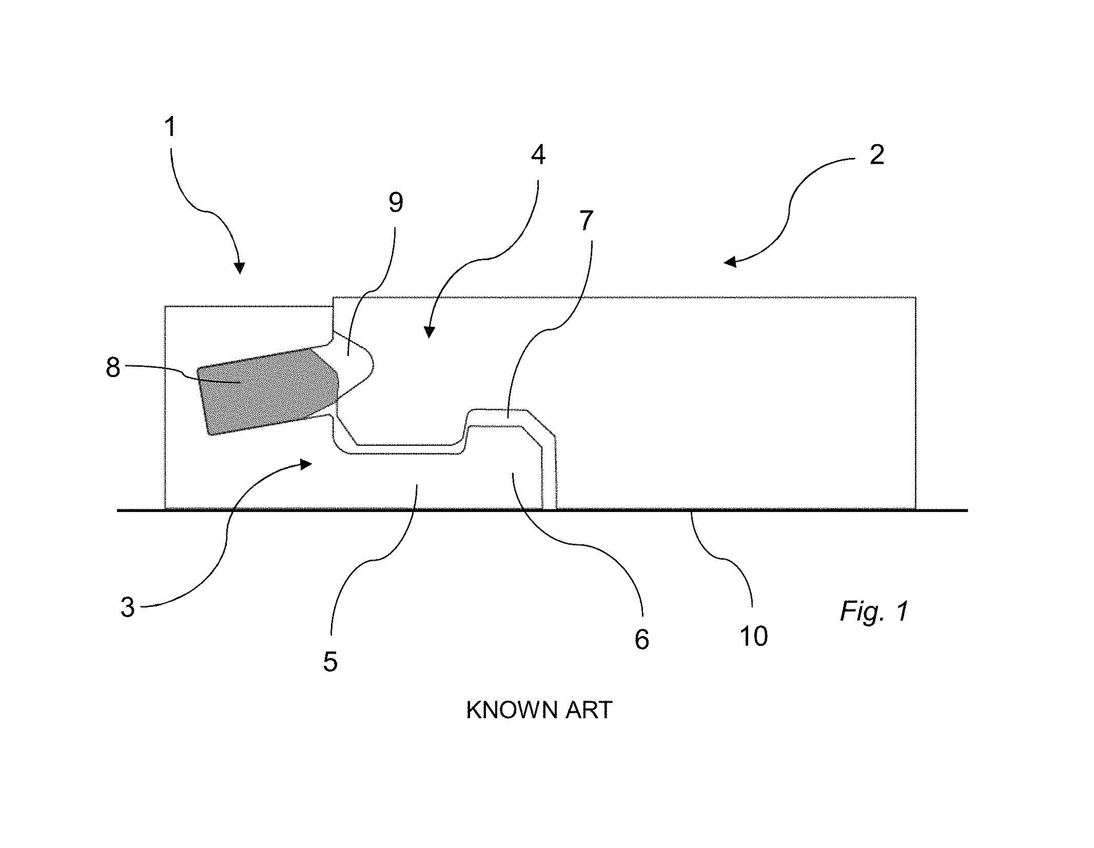
Due to tolerances allowed during manufacturing, the thickness of different floorboards may slightly differ. As a consequence, different portions of a mechanical locking system may be arranged at different heights of the floorboards. For example, the distance from the sub floor on which the floorboards are arranged to a tongue arranged on a first floorboard may be different from the distance from the sub floor to a tongue groove of a second floorboard, into which the tongue is to be inserted for locking in a vertical direction, which is shown in FIG. 1. This may result in difficulties when joining the floorboards, since the floorboards may not enter into a locking position. However, such differences in thickness of the floorboards usually does not results in problems when locking the floorboards together when the floorboards are arranged on a foam provided on the sub-floor. Such a foam is usually compressible. The compressible foam allows a thicker floorboard to be pressed towards the sub-floor such that the tongue groove on the thicker floorboard is positioned at the same height as the tongue of an adjacent floorboard.
Such an underlying foam is conventionally used when installing laminate flooring, engineered wood floorings, etc. When installing floors made of plastics, such as vinyl floorings, for example LVT (Luxury Vinyl Tiles), such a foam is not conventionally used.
As a result, the differences in thickness between different floorboards may result in difficulties when locking the floorboards together, especially when joining the floorboards by a so called fold down technique. The fold down technique involves assembling the floorboards by a vertical downward movement of one edge of one of the floorboards. As described above, floorboards having different thickness may result in the tongue groove of one floorboard being positioned at a different height than the tongue of the adjacent floorboard, resulting in difficulties when joining the floorboards, because the floorboards may not enter into a locking position.
SUMMARY
It is an object of at least certain embodiments of the present disclosure to provide an improvement over the above described techniques and known art.
A further object of at least certain embodiments of the present disclosure is to facilitate locking of floorboards by means of a mechanical locking system.
Another object of at least certain embodiment of the present disclosure is to facilitate locking of floorboards by means of a mechanical locking system when the floorboards have different thicknesses.
A further object of at least certain embodiment of the present disclosure is to facilitate locking of floorboards by means of a mechanical locking system when no underlying foam is used.
At least some of these and other objects and advantages that will be apparent from the present disclosure have been achieved by floorboards provided with a mechanical locking system comprising a locking strip protruding from a first edge of a first floorboard, wherein the locking strip is provided with a locking element configured to cooperate with a locking groove at a lower side of a second edge of a second floorboard for locking the first and second edge in the horizontal direction. The first and the second edges are configured to be assembled by a vertical downward motion of the second edge towards the first edge. The second edge is provided with a calibrating groove adjacent the locking groove.
An advantage of embodiments of the present disclosure is that the calibrating groove compensates for floorboards having different thicknesses, especially a difference in thickness at the edges of the floorboards. The calibrating groove allows the second edge to be pushed towards a sub-floor on which the floorboards are arranged. Thereby, the second edge may be displaced such that an upper side of the second floorboard is aligned with an upper side of the first floorboard at the first and second edges, respectively, even if the thickness of the second floorboard exceeds the thickness of the first floorboard.
Another advantage of embodiments of the present disclosure is that locking of the floorboards may be facilitated. Conventionally, due to different floorboards having different thicknesses, locking of portions of the mechanical locking system such as a tongue and a tongue groove, may be hindered. The tongue may have difficulties in entering into engagement with the tongue groove for locking as discussed above. By providing the calibrating groove of the present disclosure, the second edge may be bent downwards until a locking position in which the tongue enters into the tongue groove is reached.
At least the second edge may be flexible.
At least the second floorboard may be flexible. The flexibility or resiliency of the second edge, or of the floorboard, allows the second edge to be bent downwards towards the sub-floor.
At least the second floorboard may comprise a plastic material, preferably a thermoplastic material, or an elastomer.
A core of the second floorboard may comprise a plastic material, preferably a thermoplastic material, or an elastomer.
The calibrating groove may be open towards the locking groove.
The depth of the calibrating groove may substantially equal or exceed a mean variation in thickness between the floorboards.
The depth of the calibrating groove may substantially equal a difference in thickness between the first and the second floorboard at the first and the second edge.
The calibrating groove may be arranged at the lower side of the second floorboard.
The locking element may comprise a curved outer upper part. The locking groove may have a shape complimentary to the shape of the locking element.
The first or the second edge may be provided with a tongue configured to cooperate with a tongue groove at the other of the first or the second edge for locking the first and the second edge in the vertical direction.
The tongue may be formed of the same material as the first or the second edge.
The tongue may be provided at the second edge and extend vertically downward from an upper side of the second floorboard.
The width of the tongue may increase with a distance from the upper side of the second floorboard.
The tongue may be a displaceable tongue arranged in a displacement groove. The displaceable tongue may be configured to enter into engagement with the tongue groove when the floorboards are in a locking position.
According to a second aspect, the present disclosure is realized by a method for producing a mechanical locking system at edges of a first and second floorboard. The method comprises the step of:
providing a first and a second floorboard, wherein the first floorboard has a first thickness and the second floorboard has a second thickness different from the first thickness,
forming a locking groove at a lower side of a second edge of the first and second floorboard, and
forming a calibrating groove at the lower side of the second edge of at least one of the first and second floorboard with a tool, wherein the tool is positioned at a fixed position relative an upper side of the first and second floorboard.
The method according to the second aspect of the present disclosure may incorporate the advantages of the floorboards, which have previously been discussed such that the previous discussion is applicable also to the method for producing a mechanical locking system.
The method may further comprise positioning a bottom surface of the calibrating groove at a fixed distance from the upper side of the first and second floorboard.
The bottom surface of the calibrating groove may positioned such that a depth of the calibrating groove substantially equals or exceeds a mean variation in thickness between the floorboards.
The bottom surface of the calibrating groove may be positioned such that a depth of the calibrating groove substantially equals a difference in thickness between the first and the second floorboard.
The locking groove and the calibrating groove may be formed adjacent each other. The calibrating groove may be formed in the lower side of the first floorboard and the second floorboard.
The calibrating groove may be open towards the locking groove.
The method may further comprise forming a locking strip provided with a locking element at a first edge of the first and the second floorboard, wherein the locking element is configured to cooperate with the locking groove. The locking element may be configured to cooperate with the locking groove for locking in a horizontal direction.
The method may further comprise forming a tongue groove at the first edge or the second edge of the first floorboard and the second floorboard, and providing a tongue at the other of the first edge and the second edge of the first floorboard and the second floorboard, wherein tongue is configured to cooperate with the tongue groove. The tongue may be configured to cooperate with the tongue groove for locking in a vertical direction.
The step of providing a tongue may comprise forming a displacement groove at the other of the first edge and the second edge of the first floorboard and the second floorboard, and inserting the tongue in the displacement groove, the tongue being displaceable in the displacement groove.
BRIEF DESCRIPTION OF THE DRAWINGS
The present disclosure will by way of example be described in more detail with reference to the attached drawings, which show embodiments of the present disclosure.
FIG. 1 shows floorboards arranged on sub-floor according to known art.
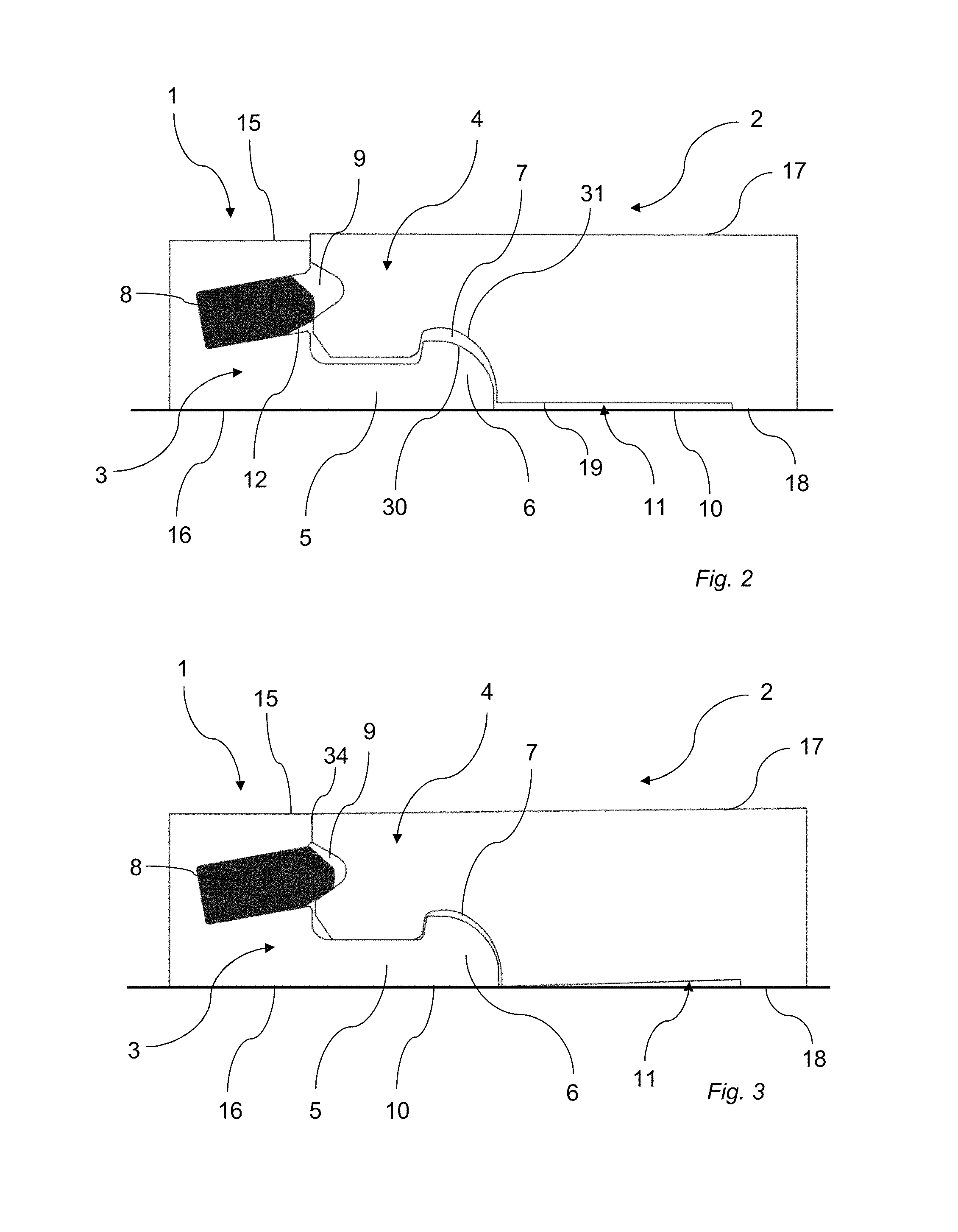
FIG. 2 shows floorboards according to an embodiment of the present disclosure.
FIG. 3 shows the floorboards of FIG. 2 in a locked position.
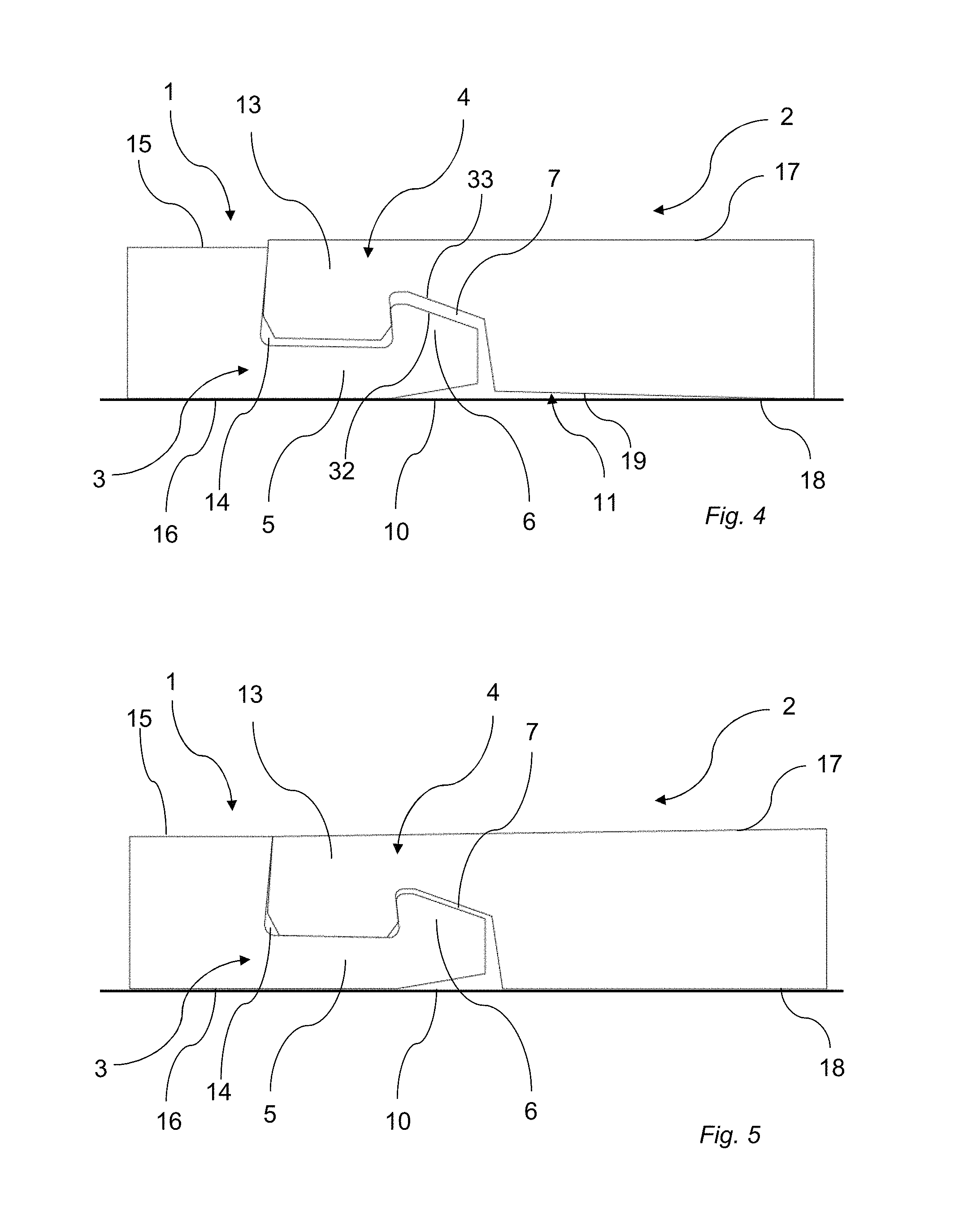
FIG. 4 shows floorboards according to another embodiment of the present disclosure.
FIG. 5 shows the floorboards of FIG. 4 in a locked position.
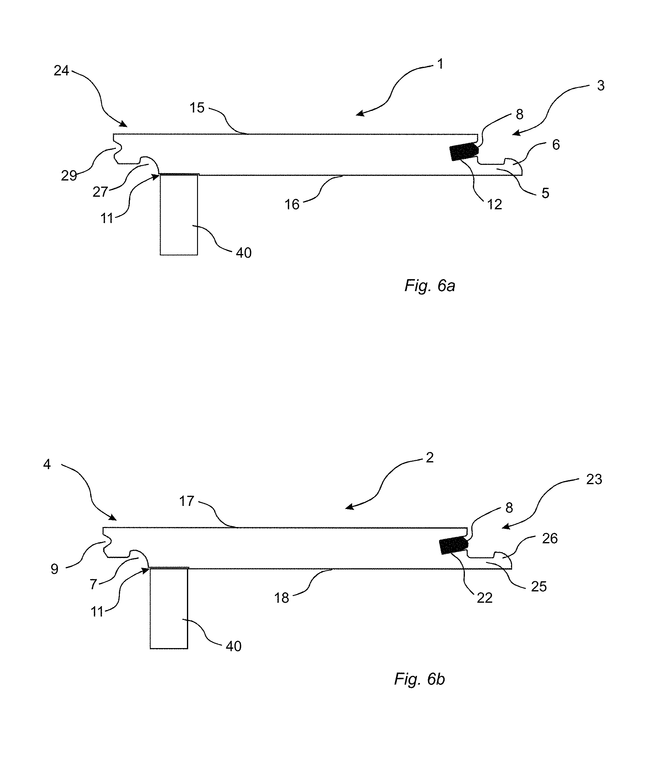
FIG. 6a shows a cross-section of a first floorboard.
FIG. 6b shows a cross-section of a second floorboard.
DETAILED DESCRIPTION
FIGS. 2, 3, 4 and 5 show a mechanical locking system of a set of floorboards comprising at least a first floorboard 1 and a second floorboard 2. FIGS. 6a and 6b show the first floorboard 1 and the second floorboard 2, respectively. The first and second floorboards 1, 2 are arranged on a sub-floor 10. The first floorboard 1 has an upper side 15 facing away from the sub-floor 10 and a lower side 16 facing toward the sub-floor 10. The second floorboard 2 has an upper side 17 facing away from the sub-floor 10 and a lower side 18 facing toward the sub-floor 10.
The first and second floorboards 1, 2 are provided with the mechanical locking system. The mechanical locking system comprises a locking strip 5. The locking strip 5 protrudes from a first edge 3 of the first floorboard 1. The locking strip 5 is provided with a locking element 6. The locking element 6 is configured to cooperate with a locking groove 7 arranged at the lower side 18 of a second edge 4 of the second floorboard 2 for locking the first and second edges 3, 4 in a horizontal direction.
The locking element 6 has an outer upper portion 30. The locking groove 7 has an outer lower portion 31. In the embodiment shown in FIGS. 2 and 3, the locking element 6 has a curved or rounded outer upper portion 30. The curved upper portion 30 may be shaped as a part of a circle or ellipse. The locking groove 7 may have a shape complimentary to the shape of the locking element 6. That is, the outer lower portion 31 of the locking groove 7 may be curved or rounded. In the embodiment shown in FIGS. 4 and 5, the locking element 6 has an inclined outer upper portion 32. The locking groove 7 may have a shape complimentary to the shape of the locking element 6. That is, the outer lower portion 33 of the locking groove 7 may be inclined. Further, a lower part of the locking element 6 facing the sub-floor 10 may be inclined relative to the sub-floor 10 as shown in FIGS. 4 and 5.
The first and second edges 3, 4 are configured to be assembled and locked together by a vertical downward motion of the second edge 4 towards the first edge 3.
The mechanical locking system may further comprise a tongue 8 and a tongue groove 9. The tongue 8 may be arranged at the first edge 3 or the second edge 4. The tongue groove 9 may be arranged at the other of the first edge 3 and the second edge 4. The tongue 8 is configured to cooperate with the tongue groove 9 for locking the first edge 3 and the second edge 4 in a vertical direction. The tongue 8 may protrude from the first edge 3 at an angle relative to the upper side 15 of the first floorboard 1 as shown in FIGS. 2 and 3. Alternatively, the tongue 8 may protrude from the first edge 3 in a horizontal direction with an angle.
As shown in FIGS. 2 and 3, the tongue 8 may be a displaceable tongue arranged in a displacement groove 12 at the first edge 3 or the second edge 4. The displaceable tongue 8 may be formed as a separate part. That is, the displaceable tongue 8 may be formed of a different material than the material of the first and second floorboards 1, 2. Such a displaceable tongue 8 is for example described in WO2007/015669. In the embodiment shown in FIGS. 2 and 3, the tongue 8 is a displaceable tongue arranged in a displacement groove 12 at the first edge 3. The tongue groove 9 is arranged at the second edge 4. The displaceable tongue 8 is displaceable within the displacement groove 12. The displaceable tongue 8 is configured to cooperate with the tongue groove 9 for locking the first edge 3 and the second edge 4 in a vertical direction.
In the embodiment shown in FIGS. 4 and 5, the tongue 13 may be formed of the same material as the first edge 3 or the second edge 4. The tongue 13 may be an integrated part of the first edge 3 or the second edge 4. In FIGS. 4 and 5, the tongue 13 is formed of the same material as the second edge 4. The tongue groove 14 is formed at the first edge 3. The tongue 13 is preferably configured to cooperate with the tongue groove 14 for locking the first edge 3 and the second edge 4 in a vertical direction. In the embodiment shown in FIGS. 4 and 5, the tongue 13 extends vertically downward from the upper side 17 of the second floorboard and protrudes horizontally. The width of the tongue 13 increases with the distance from the upper surface 17 of the second panel 2. The tongue 13 may have a dovetailed shape as seen in cross-section.
The first and second edges 3, 4 may be short edges of the first and second floorboards 1, 2, respectively. The long edges of the first and second floorboards 1, 2 may also be provided with a mechanical locking system. For example, the long edges may be provided with a mechanical locking system configured for locking floorboards together by angling. Alternatively, the long edges may be provided with a mechanical locking system of the type described above. It is also contemplated that the floorboards may be square shaped, rectangular shaped or any other polygonal shape.
In embodiments, at least the second edge 4 is flexible, elastic or resilient, such that the second edge 4 may be pushed in a vertical direction. The second edge 4 is preferably pushed downwards in the vertical direction towards the sub-floor 10. In one embodiment, the first and second floorboards 1, 2 are flexible, elastic, or resilient. The first and second floorboards 1, 2 may in this embodiment comprise a plastic material, preferably a thermoplastic material such as polyvinyl chloride (PVC), polyurethane (PU and/or PUR), polypropylene (PP), or polyethylene (PE), or a combination thereof. The thermoplastic material may be polystyrene (PS), polyethylene terephthalate (PET), polyacrylate, polyvinyl butyral, or a combination thereof. The first and second floorboards 1, 2 may also comprise an elastomer. The first and second floorboards 1, 2 may comprise a WPC (Wood Plastic Composite). The resiliency of the second edge 4 may also be obtained by removing material from the second edge 4.
In embodiments, the first and second floorboards 1, 2 may comprise one or more layers. The first and second floorboards 1, 2 may comprise a core. The mechanical locking system may be formed in the core. The first and second floorboards 1, 2 may further comprise a surface layer, preferably a decorative surface layer or a print layer arranged on an upper side of the core. The surface layer may further comprise a wear resistant layer arranged on the decorative surface layer or the print layer. The first and second floorboards 1, 2 may further comprise a backing layer arranged on a lower side of the core. The core may provide the second edge 4 flexible or resilient properties. The core may comprise a plastic material, preferably a thermoplastic material such as polyvinyl chloride (PVC), polyurethane (PU), polypropylene (PP), or polyethylene (PE)), or a combination thereof. The thermoplastic material may be polystyrene (PS), polyethylene terephthalate (PET), polyacrylate, polyvinyl butyral, or a combination thereof. The core may also comprise a WPC (Wood Plastic Composite). The core may also comprise an elastomer. It is also contemplated that the core may comprise more than one layer. For example, the core may comprise a first layer of a wood fibre based panel such as MDF or HDF and a second layer of a resilient material such as plastic, preferably comprising a thermoplastic material or an elastomer.
The first and second floorboards 1, 2 may be resilient floorboards such as Luxury Vinyl Tiles or Planks, vinyl free floorings, etc. The first and second floorboards 1, 2 may comprise a core, a surface layer arranged on an upper side of the core, and optionally a backing layer arranged on a lower side of the core. The core may comprise a thermoplastic material such as polyvinyl chloride (PVC), polyurethane (PU), polypropylene (PP), or polyethylene (PE). The core may comprise an elastomer. The surface layer may comprise one or more layers, such as a print layer, a wear resistant layer and a protective coating. The print layer and/or the wear resistant layer may comprise a thermoplastic material such as a thermoplastic foil. The thermoplastic material of the print layer and the wear resistant layer may be polyvinyl chloride (PVC), polyester, polypropylene (PP), polyethylene (PE), polystyrene (PS), polyurethane (PUR), polyethylene terephthalate (PET), polyacrylate, polyvinyl butyral, or a combination thereof. The protective coating may be a radiation curable coating such as UV curable coating.
As shown in FIGS. 2 and 3, and in FIGS. 4 and 5, the second edge 4 is provided with a calibrating groove 11. The calibrating groove 11 is arranged adjacent the locking groove 7. The calibrating groove 11 is arranged at a lower side 18 of the second floorboard 2. The calibrating groove 11 extends to the locking groove 7. The calibrating groove 11 is open towards the locking groove 7. The calibrating groove 11 extends from the lower side 18 of the floorboard 2 in a vertical direction. The calibrating groove 11 has a bottom surface 19, which may extend in a horizontal direction, or may be inclined.
In an embodiment in which the second floorboard 2 at the second edge 4 comprises a core, the calibrating groove 11 may be formed in the core. In an embodiment in which the second floorboard 2 at the second edge 4 comprises a core and a backing layer at the lower side of the core, the calibrating groove 11 may formed in the backing layer, or in the backing layer and the core.
The calibrating groove 11 is configured to adjust to differences in thickness between the first and second floorboards 1, 2, and especially configured to adjust to a difference in thickness at the first and second edges 3, 4 of the first and second floorboards 1, 2, respectively. As seen in FIGS. 2 and 4, the thickness of the second floorboard 2 at the second edge 4 exceeds the thickness of the first floorboard 1 at the first edge 3. As a consequence, the tongue groove 9 is arranged above the tongue 8 such that the tongue 8 is hindered from entering into cooperation with the tongue groove 9, as shown in FIG. 2. In the embodiment shown in FIG. 4, the tongue 13 is only partly inserted into the tongue groove 14. The locking surfaces of the tongue 13 and tongue groove 14 are only partly in engagement.
When arranged on the sub-floor 10, the presence of the calibrating groove 11 at the second edge 4 results in a distance being formed between the sub-floor 10 and the floorboard 2 at the second edge 4. The calibrating groove 11 allows that the second edge 4 to be pushed towards the sub-floor 10 to a position wherein the tongue 8, 13 can enter into engagement with the tongue groove 9, 14, which is shown in FIGS. 3 and 5. When the tongue 8, 13 engages with the tongue groove 9, 14, the first edge 3 and the second edge 4 are locked in the vertical direction. As seen in FIGS. 3 and 5, at least a portion of a bottom surface 19 of the calibrating groove 11 is abutting the sub-floor 10. The engagement of the tongue 8, 13 in the tongue groove 9, 14 locks the first edge 3 and the second edge 4 in a position wherein the second edge 4 is bent towards the sub-floor 10. Preferably, the upper side 17 of the second floorboard 2 at the second edge 4 is aligned with the upper side 15 of the first floorboard 1 at the first edge 3 when the tongue 8, 13 has entered into engagement with the tongue groove 9.
Preferably, the flexible or resilient properties of the second floorboard 2, or of the core of the second floorboard 2, help achieve the desired bending at the second edge 4. The width of the calibrating groove 11 in a horizontal direction parallel to the upper surface 17 and perpendicular to a joint plane 34 may be adjusted to material properties of the second floorboard 2. If the second floorboard 2 is more rigid, the width of the calibrating groove 11 should be increased in order to obtain the desired bending at the second edge 4. If the second floorboard 2 is more flexible and/or resilient, the width of the calibrating groove 11 can be reduced compared to the more rigid floorboard. By adjusting the width of the calibrating groove 11, the desired flexibility and resiliency of the second floorboard 2 for allowing bending of the second edge 4 towards the sub-floor 10 can be achieved.
The calibrating groove 11 preferably extends along the extension of the second edge 4 in a horizontal direction parallel to the upper surface 17 and horizontally along the joint plane 34. The calibrating groove 11 is preferably continuous. In an alternative embodiment, the calibrating groove 11 may be non-continuous in the horizontal direction parallel to the upper surface 17 and horizontally along the joint plane 34.
Preferably, the depth of the calibrating groove 11 substantially equals the difference in thickness between the first floorboard 1 and the second floorboard 2. Preferably, the depth of the calibrating groove 11 is less than 0.5 mm, preferably less than 0.3 mm, more preferably less than 0.2 mm.
The calibrating groove 11 can be formed when forming the mechanical locking system. The depth of the calibrating groove 11 can be chosen as a mean difference in thickness between several floorboards, or as a depth exceeding the mean difference in thickness between several floorboards. Floorboards having a thickness exceeding a desired thickness may be provided with a calibrating groove 11. Floorboards having a thickness less than the desired thickness may not be provided with any calibrating groove 11.
FIG. 6a shows the first floorboard 1 in cross-section. The first floorboard 1 comprises the first edge 3 and a second edge 24. FIG. 6b shows the second floorboard 2 in cross-section. The second floorboard 2 comprises the second edge 4 and a first edge 23. The first and second floorboards 1, 2 in FIGS. 6a-6b correspond to the first and second floorboards 1, 2 in FIGS. 2-5 described above. FIGS. 2-5 show joining of the first and second floorboards 1, 2 while FIGS. 6a-6b show the floorboards separately. The description of the first and second floorboards 1, 2 with reference to FIGS. 2-5 above is applicable also for the first and second floorboards 1, 2 described below with reference to FIGS. 6a-6b, and vice versa.
A method of forming a mechanical locking system at edges of the first and second floorboards 1, 2 will now be described with reference to FIGS. 6a-6b. A locking groove 27 is formed at a lower side 16 of the second edge 24 of the first floorboard 1 having a first thickness. A locking groove 7 is also formed at a lower side 18 of the second edge 4 of the second floorboard 2 having a second thickness. The thickness of the first floorboard 1 may differ from the thickness of the second floorboard 2.
If the thickness of any one of the first and second floorboards 1, 2, preferably measured at the second edge 4, 24 where the locking groove 7, 27 is formed, exceeds a predetermined thickness, a calibrating groove 11 is formed in that floorboard. If the thickness is equal to or less than a predetermined thickness, no calibrating groove is formed. In FIGS. 6a-6b, a calibrating groove 11 has been formed in both the first and second floorboards 1,2.
The calibrating groove 11 is formed by a tool 40. The tool 40 is positioned at a fixed distance from an upper side 15, 17 of the first floorboard 1 and the second floorboard 2. The fixed distance is the same between the upper side 15 of the first floorboard 1 and the tool 40 and between the upper side 17 of the second floorboard 2 and the tool 40. The fixed distance corresponds to a predetermined desired value of the thickness. The predetermined desired value may correspond to a mean thickness of at least the first and second floorboards.
By the tool 40 being arranged at a fixed position, any floorboard having a thickness exceeding said distance will be provided with a calibrating groove 11. The tool 40 may be a knife, a heating device adapted to melt a portion of the floorboard, a scraping tool, a carving tool, etc.
The first floorboard 1 and the second floorboard 2 are preferably conveyed by the same conveyor element when the floorboards 1, 2 pass the tool 40. The distance between the conveyor element and the tool 40 is fixed. Preferably, the upper side 15, 17 of the first floorboard 1 and the second floorboard 2, respectively, abut the conveyor element.
The calibrating groove 11 is formed at the lower side 16, 18 of the second edge 4, 24 of the first and second floorboards 1, 2. The calibrating groove 11 may be formed by cutting, scraping, or melting a portion of the floorboard. The calibrating groove 11 is formed such that the calibrating groove 11 is open towards the locking groove 7, 27.
The calibrating groove 11 is arranged adjacent the locking groove 7, 27. Preferably, the first and second floorboards 1, 2 are conveyed in a horizontal direction between a first position wherein the locking groove 7, 27 is formed and a second position wherein the calibrating groove 11 is formed.
The calibrating groove 11 has a bottom surface 19. The calibrating groove 11 is formed such that the bottom surface 19 of the calibrating groove 11 of a first floorboard 1 and the bottom surface 19 of the calibrating groove 11 of a second floorboard 2 are positioned at substantially the same distance from the upper side 15, 17 of the first and second floorboards 1, 2, respectively. A distance between the upper side 15, 17 of a respective floorboard and the bottom surface 19 of each calibrating groove 11 is essentially the same for the first and second floorboards 1, 2. Even if the first and second floorboards 1, 2 have a different thickness, the bottom surface 19 of each calibrating groove 11 is positioned at a substantially equal distance from the upper side 15, 17 of the respective first and second floorboards 1, 2. Consequently, the depth of the calibrating groove 11 may differ from one floorboard to another depending on the original thickness of the floorboard at the second edge 4, 24.
The method may further comprise forming a locking strip 5 provided with a locking element 6 at the first edge 3 of the first floorboard 1 and forming a locking strip 25 provided with a locking element 26 at the first edge 23 of the second floorboard 2. The locking element 6, 26 is configured to cooperate with the locking groove 7, 27 for locking in a horizontal direction.
The method may further comprise forming a tongue groove 9 at the second edge 4 of the second floorboard 2 and forming a tongue groove 29 at the second edge 24 of the first floorboard 1. A displacement groove 12 may be formed at the first edge 3 of the first floorboard 1 and a displacement groove 22 is formed at the first edge 23 of the second floorboard 2. The method may further comprise inserting a displaceable tongue 8 into each displacement groove 12 and 22 as shown in FIGS. 6a-6b. The displaceable tongue 8 is displaceable within the displacement groove 12, 22. The displaceable tongue 8 is adapted to lock the floorboards in the vertical direction. Alternatively, vertical locking may be obtained by the tongue 13 and the tongue groove 14 shown in FIGS. 4 and 5.
It is to be understood that the locking strip 25, the locking element 26 and the displacement groove 22 of the first edge 23 of the second floorboard 2 essentially correspond to the locking strip 5, the locking element 6 and the displacement groove 12 of the first edge 3 of the first floorboard 1, and that the description above with reference to FIGS. 2-5 also is applicable to FIGS. 6a-6b.
It is to be understood that locking groove 27 and the tongue groove 29 of the second edge 24 of the first floorboard 1 essentially correspond to the locking groove 7 and the tongue groove 9 of the second edge 4 of the second floorboard 2, and that the description above with reference to FIGS. 2-5 also is applicable to FIGS. 6a-6b.
The first and second edges 3, 4, 23, 24 may be short edges of the first and second floorboards 1, 2. The long edges of the first and second floorboards 1, 2 may be provided with a mechanical locking system. For example, the long edges may be provided with a mechanical locking system configured for locking floorboards together by angling. Alternatively, the long edges may be provided with a mechanical locking system of the type described above. It is also contemplated that the floorboards may be square shaped, rectangular shaped or any other shape. It is contemplated that there are numerous modifications of the embodiments described herein, which are still within the scope of the present disclosure.
By upper side 15, 17 of the floorboards 1, 2 is meant a side facing away from the sub-floor 10 when the floorboards are installed. However, during production, the upper surface 15, 17 may not necessary facing upwards but may temporarily facing downwards.
It is further contemplated that the calibrating groove 11 may have any shape. For example, the calibrating groove may be U-shaped as shown in FIGS. 2-3. Furthermore, the bottom surface 19 of the calibrating groove 11 may be inclined, as shown in FIGS. 4-5.
Furthermore, it is contemplated that the mechanical locking system described above with reference to FIGS. 2-6 may be used without the calibrating groove 11. For example, floorboards having a mechanical locking system may be provided, comprising a locking strip 5 protruding from a first edge 3 of a first floorboard 1. The locking strip 5 may be provided with a locking element 6 configured to cooperate with a locking groove 7 at a lower side 18 of a second edge 4 of a second floorboard 2 for locking the first edge 3and the second edge 4 in the horizontal direction. The locking element 6 comprises a curved outer upper part 30. The locking groove 7 may have a curved outer lower part 31.
* * * * *
References
D00000
D00001
D00002
D00003
D00004
XML
uspto.report is an independent third-party trademark research tool that is not affiliated, endorsed, or sponsored by the United States Patent and Trademark Office (USPTO) or any other governmental organization. The information provided by uspto.report is based on publicly available data at the time of writing and is intended for informational purposes only.
While we strive to provide accurate and up-to-date information, we do not guarantee the accuracy, completeness, reliability, or suitability of the information displayed on this site. The use of this site is at your own risk. Any reliance you place on such information is therefore strictly at your own risk.
All official trademark data, including owner information, should be verified by visiting the official USPTO website at www.uspto.gov. This site is not intended to replace professional legal advice and should not be used as a substitute for consulting with a legal professional who is knowledgeable about trademark law.