Drill
Kawakami , et al.
U.S. patent number 10,300,534 [Application Number 15/504,484] was granted by the patent office on 2019-05-28 for drill. This patent grant is currently assigned to SUMITOMO ELECTRIC HARDMETAL CORP.. The grantee listed for this patent is SUMITOMO ELECTRIC HARDMETAL CORP.. Invention is credited to Masaaki Jindai, Yuma Kawakami, Keiji Kinoshita, Daisuke Murakami.


| United States Patent | 10,300,534 |
| Kawakami , et al. | May 28, 2019 |
Drill
Abstract
Provided is a drill having a flat-shaped drill tip and excellent in cutting edge strength and chip removability. The drill includes: a cutting edge extending in a direction at an angle .alpha. of not less than 85.degree. and not more than 90.degree. with respect to a drill axis (line O-O); a flank face contiguous to the cutting edge and having a clearance angle .beta. of not less than 5.degree. and not more than 10.degree. with respect to the drill axis (line O-O); and a rake face located opposite to the flank face across the cutting edge, the cutting edge includes a recess receding in a direction parallel to the drill axis (line O-O), and the rake face includes a front clearance formed at a side of an outer periphery of the drill.
| Inventors: | Kawakami; Yuma (Itami, JP), Murakami; Daisuke (Itami, JP), Jindai; Masaaki (Itami, JP), Kinoshita; Keiji (Itami, JP) | ||||||||||
|---|---|---|---|---|---|---|---|---|---|---|---|
| Applicant: |
|
||||||||||
| Assignee: | SUMITOMO ELECTRIC HARDMETAL
CORP. (Itami-shi, JP) |
||||||||||
| Family ID: | 55533009 | ||||||||||
| Appl. No.: | 15/504,484 | ||||||||||
| Filed: | August 19, 2015 | ||||||||||
| PCT Filed: | August 19, 2015 | ||||||||||
| PCT No.: | PCT/JP2015/073223 | ||||||||||
| 371(c)(1),(2),(4) Date: | February 16, 2017 | ||||||||||
| PCT Pub. No.: | WO2016/042967 | ||||||||||
| PCT Pub. Date: | March 24, 2016 |
Prior Publication Data
| Document Identifier | Publication Date | |
|---|---|---|
| US 20170232529 A1 | Aug 17, 2017 | |
Foreign Application Priority Data
| Sep 18, 2014 [JP] | 2014-189933 | |||
| Current U.S. Class: | 1/1 |
| Current CPC Class: | B23B 51/00 (20130101); B23B 51/02 (20130101); B23B 2251/18 (20130101); B23B 2251/04 (20130101); Y10T 408/9097 (20150115); B23B 2251/08 (20130101); B23B 2251/14 (20130101) |
| Current International Class: | B23B 51/02 (20060101); B23B 51/00 (20060101) |
References Cited [Referenced By]
U.S. Patent Documents
| 2646701 | July 1953 | Letien |
| 4802799 | February 1989 | Rachev |
| 5011342 | April 1991 | Hsu |
| 5452971 | September 1995 | Nevills |
| 6135681 | October 2000 | Nuzzi |
| 6371702 | April 2002 | DeWald, Jr. |
| 2007/0134071 | June 2007 | Reinhardt et al. |
| 2008/0003072 | January 2008 | Kim et al. |
| 2008/0166196 | July 2008 | Zhu |
| 2009/0317202 | December 2009 | Zhu |
| 2012/0201619 | August 2012 | Olsson |
| 102632277 | Aug 2012 | CN | |||
| 3730377 | Mar 1989 | DE | |||
| 102010048331 | Jan 2012 | DE | |||
| 2484470 | Aug 2012 | EP | |||
| 2004-141970 | May 2004 | JP | |||
| 2008-500190 | Jan 2008 | JP | |||
| 2009-056534 | Mar 2009 | JP | |||
| 2012-161912 | Aug 2012 | JP | |||
| 2014000642 | Jan 2014 | JP | |||
Other References
|
International Search Report in counterpart International Application No. PCT/JP2015/073223, dated Sep. 15, 2015. cited by applicant. |
Primary Examiner: Howell; Daniel W
Assistant Examiner: Su; Chwen-Wei
Attorney, Agent or Firm: Baker Botts L.L.P. Sartori; Michael A.
Claims
The invention claimed is:
1. A drill comprising: a cutting edge extending in a direction at an angle of not less than 85.degree. and not more than 90.degree. with respect to a drill axis; a flank face contiguous to the cutting edge and having a clearance angle of not less than 5.degree. and not more than 10.degree. with respect to a perpendicular to the drill axis; and a rake face located opposite to the flank face across the cutting edge, the cutting edge including a recess receding in a direction parallel to the drill axis, the rake face including a front clearance formed at a side of an outer periphery of the drill, the recess receding from the top of the cutting edge and forming an arc shape as the drill is seen sideways, wherein the rake face includes a thinning portion formed at a side of the drill axis, the thinning portion includes a linear portion and a curved portion as seen from above a tip of the drill, the linear portion is shaped to extend beyond the drill axis, and an outer end of the curved portion is located inside the outer periphery of the drill.
2. The drill according to claim 1, wherein the recess has a width of not less than 50% and not more than 70% of a width of a part of the cutting edge from the drill axis to an outer peripheral end of the drill.
3. The drill according to claim 1, wherein the recess has a depth of not less than 2% and not more than 5% of a diameter of the drill.
4. The drill according to claim 1, wherein the linear portion of the thinning portion is formed in parallel with the front clearance as seen from above the tip of the drill.
Description
TECHNICAL FIELD
The present invention relates to a drill, and more specifically relates to a drill having a flat-shaped tip.
BACKGROUND ART
Drills having the point angle set to 120.degree. to 140.degree. are provided as a standard model.
Such drills, however, have a problem of low accuracy of the hole position when the drill bites a non-flat surface such as inclined surface in processing the non-flat surface. Thus, drills suitable for processing a non-flat surface have been developed.
Japanese Patent Laying-Open No. 2004-141970 (PTD 1) discloses a drill having a point angle of 170.degree. to 180.degree. as a drill for drilling a hole in an inclined surface.
Japanese Patent Laying-Open No. 2009-56534 (PTD 2) discloses a drill functioning as a counterbore drill for drilling a guide hole or performing boring as preprocessing before drilling a hole in an inclined surface. The counterbore drill has a point angle of 170.degree. to 190.degree., and includes two secondary cutting edges extending outward from the chisel through thinning, a primary cutting edge in a concave shape extending outward from each secondary cutting edge, and an outer cutting edge extending from each primary cutting edge to a leading edge and receding in the rotational direction of the drill. The outer cutting edge has a receding angle of -1.degree. to -20.degree..
A drilling operation in a workpiece by a drill of a standard model forms a blind hole with a cone-shaped bottom. For certain applications, however, blind holes with a flat bottom are desired. For such applications, Japanese National Patent Publication No. 2008-500190 (PTD 3) discloses a drill having a point angle of 180.degree..
CITATION LIST
Patent Document
PTD 1: Japanese Patent Laying-Open No. 2004-141970 PTD 2: Japanese Patent Laying-Open No. 2009-56534 PTD 3: Japanese National Patent Publication No. 2008-500190
SUMMARY OF INVENTION
Technical Problem
The technique of Japanese Patent Laying-Open No. 2004-141970 (PTD 1) has a problem that the drill is likely to be damaged due to a heavy load on the outer peripheral portion of the drill tip, because the drill tip has a concave shape. The technique of Japanese Patent Laying-Open No. 2009-56534 (PTD 2) also has a problem that the drill is likely to be damaged due to a heavy load on the outer peripheral portion of the drill tip if the point angle is more than 180.degree..
Moreover, the technique of Japanese National Patent Publication No. 2008-500190 (PTD 3) has a problem of low chip removability due to less influence of a chip flute on chip disposal because the drill tip is a linear cutting edge with a point angle of 180.degree..
In view of this, an object of the present invention is to provide a drill having a flat-shaped drill tip and excellent in cutting edge strength and chip removability.
Solution To Problem
A drill according to an aspect of the present invention is (1) a drill including: a cutting edge extending in a direction at an angle of not less than 85.degree. and not more than 90.degree. with respect to a drill axis; a flank face contiguous to the cutting edge and having a clearance angle of not less than 5.degree. and not more than 10.degree. with respect to a perpendicular to the drill axis; and a rake face located opposite to the flank face across the cutting edge, the cutting edge includes a recess receding in a direction parallel to the drill axis, and the rake face includes a front clearance formed at a side of an outer periphery of the drill.
Advantageous Effects of Invention
According to the above-described aspect, a drill having a flat-shaped drill tip and excellent in cutting edge strength and chip removability can be provided.
BRIEF DESCRIPTION OF DRAWINGS
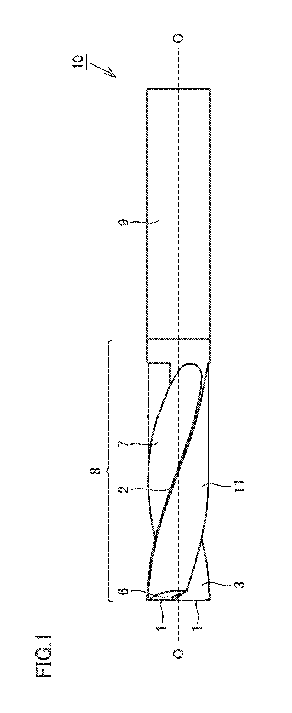
FIG. 1 is a side view illustrating a representative example of the structure of a drill according to an aspect of the present invention.
FIG. 2 is a side view of the drill shown in FIG. 1 rotated 90.degree. about a drill axis indicated by the line O-O.
FIG. 3 is an enlarged side view of a tip portion of the drill shown in FIG. 1.
FIG. 4 is an enlarged side view of the tip portion of the drill shown in FIG. 2.
FIG. 5 is an enlarged front view of the tip portion of the drill shown in FIG. 1.
DESCRIPTION OF EMBODIMENTS
[Description of Embodiments of the Invention]
Initially, aspects of the present invention will be described one by one.
A drill according to an aspect of the present invention is
(1) a drill including: a cutting edge extending in a direction at an angle of not less than 85.degree. and not more than 90.degree. with respect to a drill axis; a flank face contiguous to the cutting edge and having a clearance angle of not less than 5.degree. and not more than 10.degree. with respect to a perpendicular to the drill axis; and a rake face located opposite to the flank face across the cutting edge, the cutting edge including a recess receding in a direction parallel to the drill axis, and the rake face including a front clearance formed at a side of an outer periphery of the drill. Accordingly, a drill having a flat-shaped drill tip and excellent in cutting edge strength and chip removability can be provided.
(2) Preferably, the rake face includes a thinning portion formed at a side of the drill axis. Accordingly, the chip removability, the cutting edge strength, and biting of the drill are improved.
(3) Preferably, the recess has a width of not less than 50% and not more than 70% of a width of a part of the cutting edge from the drill axis to an outer peripheral end of the drill. Accordingly, the cutting edge strength and the chip removability of the drill are improved.
(4) Preferably, the recess has a depth of not less than 2% and not more than 5% of a diameter of the drill. Accordingly, the cutting edge strength and the chip removability of the drill are improved.
(5) Preferably, the thinning portion includes a linear portion and a curved portion as seen from above a tip of the drill, the linear portion is shaped to extend beyond the drill axis, and an outer end of the curved portion is located inside the outer periphery of the drill. Accordingly, the stiffness of the drill is improved and the stability during processing by the drill is enhanced.
(6) Preferably, the linear portion of the thinning portion is formed in parallel with the front clearance as seen from above the tip of the drill. Accordingly, the cutting edge strength is improved while the chip removability is maintained.
[Details of Embodiments of the Invention]
A specific example of the drill according to an embodiment of the present invention will hereinafter be described with reference to the drawings.
FIG. 1 is a side view illustrating a representative example of the structure of a drill according to an aspect of the present invention. FIG. 2 is a side view of the drill shown in FIG. 1 rotated 90.degree. about a drill axis (line O-O). FIG. 3 is an enlarged side view of a tip portion of the drill shown in FIG. 1. FIG. 4 is an enlarged side view of the tip portion of the drill shown in FIG. 2. FIG. 5 is an enlarged front view of the tip portion of the drill shown in FIG. 1.
A drill 10 according to an embodiment of the present invention includes a drill shank 9 for connecting the drill to a holder, and a body 8 formed contiguously to the top end of drill shank 9. Body 8 has a side surface in the longitudinal direction. In the side surface, a spirally twisted flute 7 is formed and an outer peripheral portion 11 smaller in depth than the twisted flute is formed along twisted flute 7. Twisted flute 7 opens at the drill tip. A part of the boundary of the opening forms a cutting edge 1. Another part of the boundary of the opening is contiguous to a flank face 6. The boundary between twisted flute 7 and outer peripheral portion 11 includes a part which is contiguous to cutting edge 1. At this part of the boundary, a margin 2 is formed. An inwardly curved surface forms twisted flute 7. The inwardly curved surface near cutting edge 1 is a rake face 3. At the drill tip, a part of rake face 3 at a side of the drill axis is cut to form a thinning portion 5. The outer peripheral edge corner of rake face 3 is chamfered to form a front clearance 4.
Thinning portion 5 includes a linear portion and a curved portion. The linear portion is formed beyond the drill axis. An outer end of the curved portion is formed to be located inside the outer periphery of the drill. Accordingly, the stiffness of the drill is improved and the stability during processing by the drill is enhanced.
Drill 10 includes cutting edge 1 extending in a direction at an angle of not less than 85.degree. and not more than 90.degree. with respect to the drill axis (line O-O). Cutting edge 1 includes two cutting edges connected to each other in the vicinity of the drill axis (line O-O). Drill 10 is a drill whose cutting edge has a flat shape or a very gentle convex shape. Therefore, drilling and counterboring in a non-flat surface such as inclined surface and cylindrical surface can be performed with high accuracy. Further, cross-hole drilling, tapping, and intermittent drilling can be performed with high accuracy. Moreover, generation of a burr at the opening of the hole during drilling can be suppressed. The drill axis (line O-O) herein refers to the line extending through the center of the drill in the longitudinal direction of the drill. Cutting edge 1 extending in a direction at an angle of not less than 85.degree. and not more than 90.degree. with respect to the drill axis (line O-O) means that the angle .alpha. (see FIG. 3) formed by the drill axis (line O-O) and cutting edge 1 is not less than 85.degree. and not more than 90.degree.. If angle .alpha. is less than 85.degree., it is difficult to accurately perform drilling and counterboring in a non-flat surface such as inclined surface and cylindrical surface. In contrast, if angle .alpha. is more than 90.degree., the cutting edge strength decreases.
Drill 10 includes flank face 6 which is contiguous to cutting edge 1 and has a clearance angle .beta. of not less than 5.degree. and not more than 10.degree. with respect to a perpendicular to the drill axis (line O-O). Accordingly, the drill has high wear resistance and high chipping resistance. Clearance angle .beta. herein refers to the angle .beta. (see FIG. 4) formed by flank face 6 and a perpendicular 12 to the drill axis (line O-O). If clearance angle .beta. is less than 5.degree., the clearance between the drill and the workpiece is smaller and thus wear of the cutting edge increases rapidly, resulting in decrease of the wear resistance. In contrast, if clearance angle .beta. is more than 10.degree., the strength of cutting edge 1 is insufficient and thus chipping is apt to occur, resulting in decrease of the chipping resistance.
Cutting edge 1 includes a recess 1a receding in a direction parallel to the drill axis (line O-O) as drill 10 is seen sideways. Recess 1a recedes from the top of cutting edge 1 and forms an arc shape as drill 10 is seen sideways. The shape of recess 1a is not particularly limited.
As drill 10 is seen sideways, the width W2 (hereinafter also referred to as W2) of recess 1a is preferably not less than 50% and not more than 70% of the width W1 (hereinafter also referred to as W1) of a part of cutting edge 1 from the drill axis (line O-O) to the outer peripheral end of the drill, supposing that width W1 is 100%. Width W2 of recess 1a herein refers to the maximum value of the width of recess 1a in the direction in which cutting edge 1 extends. If W2 is less than 50% of W1, the chip removability of the drill decreases. In contrast, if W2 is more than 70% of W1, the cutting edge strength of the drill decreases.
As drill 10 is seen sideways, the depth L1 (hereinafter also referred to as L1) of recess 1a is not less than 2% and not more than 5% of the drill diameter D (hereinafter also referred to as D), supposing that drill diameter D is 100%. Depth L1 of recess 1a herein refers to the maximum value of the depth of recess 1a in the direction along the drill axis (line O-O). If L1 is less than 2% of D, the chip removability of the drill decreases. In contrast, if L1 is more than 5% of D, the cutting edge strength of the drill decreases.
At the drill tip, a part of rake face 3 at a side of the drill axis is cut to form thinning portion 5. Accordingly, the chip removability and biting of drill 10 are improved. The shape of thinning portion 5 is not particularly limited, and R-type thinning, S-type thinning, or the like may be used.
At the drill tip, the outer peripheral edge of rake face 3 is chamfered to form front clearance 4. Accordingly, the cutting edge strength of the drill is improved. The shape of front clearance 4 is not particularly limited, and front clearance 4 may have a curve in R shape or a linear shape.
The boundary between twisted flute 7 and outer peripheral portion 11 includes a part which is contiguous to cutting edge 1. At this part of the boundary, margin 2 is formed. Margin 2 at the drill tip has a width W3 (hereinafter also referred to as W3), in the drill's circumferential direction, of preferably not less than 0.05 mm and not more than 0.25 mm. Further, the width W3 is preferably not less than 50% and not more than 70% of a width W4 (hereinafter also referred to as W4) of margin 2 in the drill's circumferential direction, supposing that the width W4 is 100%. The width W4 is located at a distance from the drill tip toward drill shank 9 along the drill axis (line O-O), and this distance is 0.5 times as long as drill diameter D (0.5 D). Accordingly, the cutting edge strength can be improved while the guiding ability of the drill is ensured. If the ratio of W3 to W4 is less than 50%, the guiding ability of the drill decreases. In contrast, if the ratio W3 to W4 is more than 70%, the cutting edge strength of the drill decreases.
Twisted flute 7 has a surface roughness (Ra) of preferably not more than 5 .mu.m. Accordingly, chips flow smoothly and the chip removability of the drill is improved. Further, the drill has an improved resistance to adhesion of the workpiece and is thus applicable to stainless steel. It should be noted that the surface roughness (Ra) is a center-line mean roughness determined by dividing the sum of the area between the center line and the roughness curve on the positive side of the center line and the area between the center line and the roughness curve on the negative side of the center line, by length L.
EXAMPLES
The present invention will be described in further detail in connection with Examples. It should be noted that the present invention is not limited by these Examples.
Example 1
In this example, the influence of width W2 of recess 1a of cutting edge 1 on the chip removability and the cutting edge strength of the drill was examined.
Drills having the body shapes shown in Table 1 were fabricated, and cutting was performed under the following cutting conditions. The chip removability and the cutting edge strength during cutting were evaluated.
<Cutting Conditions>
Material of Workpiece: S50C
Rotational Speed (Cutting Speed): Vc=75 m/min
Feed: f=0.08 mm/rev
Depth of Cut Hole: drill diameter.times.2 mm
<Evaluated Characteristics>
Chip Removability Good: Chips were removed without being clogged in the twisted flute. Poor: Chips were clogged in the twisted flute.
Cutting Edge Strength Good: Cutting edge was not chipped. Poor: Cutting edge was chipped.
TABLE-US-00001 TABLE 1 Sample No. 1-1 1-2 1-3 1-4 shape of material of drill cemented cemented cemented cemented drill carbide carbide carbide carbide drill diameter D (mm) 5 5 5 5 center thickness of drill (mm) 0.8 0.8 0.8 0.8 cutting edge angle .alpha. (.degree.) 90 90 90 90 clearance angle .beta. (.degree.) 5 5 5 5 rake angle (.degree.) 5 5 5 5 ratio of front clearance (%) 20 17 12 0 W3/W4 (%) 30 50 70 100 W4 (mm) 0.2 0.2 0.2 0.2 ratio of recess width (W2/W1) 0 50 70 80 (%) evaluation chip removability poor good good good cutting edge strength good good good poor
note 1: "Cutting edge angle (.degree.)" refers to angle .alpha. formed by the drill axis (line O-O) and cutting edge 1.
note 2: "Ratio of front clearance (%)" refers to the ratio of the dimension of the front clearance in the direction along cutting edge 1, relative to the width (W1) of the cutting edge from the drill axis (line O-O) to the drill's outer peripheral end, supposing that W1 is 100%.
note 3: "Ratio of recess width (W2/W1) (%)" refers to the ratio of width W2 of the recess to the width (W1) of the cutting edge from the drill axis (line O-O) to the drill's outer peripheral end, supposing that W1 is 100%.
<Results of Evaluation>
Regarding Sample 1-2 and Sample 1-3, the ratio of the recess width (W2/W1) was not less than 50% and not more than 70%, and the chip removability and the cutting edge strength were high.
Regarding Sample 1-1, the recess was not formed in the cutting edge, and the chip removability was insufficient.
Regarding Sample 1-4, the recess was formed in the whole cutting edge, and the cutting edge strength was insufficient.
Example 2
In this example, the influence of the depth (L1) of recess 1a of cutting edge 1 on the chip removability and the cutting edge strength of the drill was examined.
Drills having the body shapes shown in Table 2 were fabricated, and cutting was performed under the following cutting conditions. At this time, the curvature of the cutting edge as seen from above the drill tip was adjusted to change the depth (L1) of recess 1a of cutting edge 1. Then, the chip removability and the cutting edge strength during cutting were evaluated.
<Cutting Conditions>
Material of Workpiece: S50C
Rotational Speed (cutting speed): Vc=75 m/min
Feed: f=0.08 mm/rev
<Evaluated Characteristics>
Chip Removability Good: Chips were removed without being clogged in the twisted flute. Poor: Chips were clogged in the twisted flute.
Cutting Edge Strength Good: Cutting edge was not chipped. Fair: Minute chipping occurred.
TABLE-US-00002 TABLE 2 Sample No. 2-1 2-2 2-3 2-4 2-5 shape of material of drill cemented cemented cemented cemented cemented drill carbide carbide carbide carbide carbide drill diameter D (mm) 5 5 5 5 5 center thickness of drill (mm) 0.8 0.8 0.8 0.8 0.8 cutting edge angle .alpha. (.degree.) 90 90 90 90 90 clearance angle .beta. (.degree.) 5 5 5 5 5 rake angle (.degree.) 5 5 5 5 5 ratio of front clearance (%) 15 15 15 15 15 ratio of recess width (W2/W1) 60 60 60 60 60 (%) ratio of recess depth (L1/D) 0 2 4 5 10 (%) evaluation chip removability poor good good good good cutting edge strength good good good good fair
note 1: "Cutting edge angle (.degree.)" refers to angle .alpha. formed by the drill axis (line O-O) and cutting edge 1.
note 2: "Ratio of front clearance (%)" refers to the ratio of the dimension of the front clearance in the direction along cutting edge 1, relative to the width (W1) of the cutting edge from the drill axis (line O-O) to the drill's outer peripheral end, supposing that W1 is 100%.
note 3: "Ratio of recess width (W2/W1) (%)" refers to the ratio of width W2 of the recess to the width (W1) of the cutting edge from the drill axis (line O-O) to the drill's outer peripheral end, supposing that W1 is 100%.
note 4: "Ratio of recess depth (L1/D) (%)" refers to the ratio of depth L1 of the recess to drill diameter D, supposing that D is 100%.
<Results of Evaluation>
Regarding Sample 2-2, Sample 2-3, and Sample 2-4, the ratio of the recess depth (L1/D) was not less than 2% and not more than 5%, and the chip removability and the cutting edge strength were high. Particularly regarding Sample 2-2 and Sample 2-3, the ratio of the recess depth (L1/D) was not less than 2% and not more than 4%, and the chip removability and the cutting edge strength were significantly high.
Regarding Sample 2-1, the recess was not formed in the cutting edge, and the chip removability was insufficient.
Regarding Sample 2-5, the ratio of the recess depth (L1/D) was 10%, and the cutting edge strength was insufficient.
It should be construed that embodiments and examples disclosed herein are given by way of illustration in all respects, not by way of limitation. It is intended that the scope of the present invention is defined by claims, not by the embodiments above, and encompasses all modifications and variations equivalent in meaning and scope to the claims.
INDUSTRIAL APPLICABILITY
The drill according to an aspect of the present invention is useful when used for sophisticated counterboring, cross-hole drilling, tapping, intermittent hole drilling, counterboring in an inclined surface, drilling in an inclined surface, counterboring in a cylindrical surface, drilling in a cylindrical surface, and the like.
REFERENCE SIGNS LIST
1 cutting edge; 1a recess; 2 margin; 3 rake face; 4 front clearance; 5 thinning portion; 6 flank face; 7 twisted flute; 8 body; 9 drill shank; 10 drill; 11 outer peripheral portion; 12 perpendicular
* * * * *
D00000
D00001
D00002
D00003
D00004
XML
uspto.report is an independent third-party trademark research tool that is not affiliated, endorsed, or sponsored by the United States Patent and Trademark Office (USPTO) or any other governmental organization. The information provided by uspto.report is based on publicly available data at the time of writing and is intended for informational purposes only.
While we strive to provide accurate and up-to-date information, we do not guarantee the accuracy, completeness, reliability, or suitability of the information displayed on this site. The use of this site is at your own risk. Any reliance you place on such information is therefore strictly at your own risk.
All official trademark data, including owner information, should be verified by visiting the official USPTO website at www.uspto.gov. This site is not intended to replace professional legal advice and should not be used as a substitute for consulting with a legal professional who is knowledgeable about trademark law.