Content-based encoding in a multiple routing path communications system
Dhuse , et al.
U.S. patent number 10,298,957 [Application Number 15/817,104] was granted by the patent office on 2019-05-21 for content-based encoding in a multiple routing path communications system. This patent grant is currently assigned to INTERNATIONAL BUSINESS MACHINES CORPORATION. The grantee listed for this patent is International Business Machines Corporation. Invention is credited to Andrew D. Baptist, Greg R. Dhuse, S. Christopher Gladwin, Gary W. Grube, Timothy W. Markison, Jason K. Resch, Ilya Volvovski.


View All Diagrams
| United States Patent | 10,298,957 |
| Dhuse , et al. | May 21, 2019 |
Content-based encoding in a multiple routing path communications system
Abstract
A method includes partitioning a data file into first priority data and second priority data. The method further includes determining first error coding dispersal storage function parameters for the first priority data based on first transmission reliability level and second error coding dispersal storage function parameters for the second priority data based on second transmission reliability level. The method further includes dispersed error encoding the first priority data using the first error coding dispersal storage function parameters to produce first plurality of sets of encoded data slices and dispersed error encoding the second priority data using the second error coding dispersal storage function parameters to produce second plurality of sets of encoded data slices. The method further includes selecting one or more routing paths from a plurality of candidate routing paths and transmitting the first plurality of sets of encoded data slices via the one or more routing paths.
| Inventors: | Dhuse; Greg R. (Chicago, IL), Baptist; Andrew D. (Mt. Pleasant, WI), Volvovski; Ilya (Chicago, IL), Grube; Gary W. (Barrington Hills, IL), Markison; Timothy W. (Mesa, AZ), Gladwin; S. Christopher (Chicago, IL), Resch; Jason K. (Chicago, IL) | ||||||||||
|---|---|---|---|---|---|---|---|---|---|---|---|
| Applicant: |
|
||||||||||
| Assignee: | INTERNATIONAL BUSINESS MACHINES
CORPORATION (Armonk, NY) |
||||||||||
| Family ID: | 61561129 | ||||||||||
| Appl. No.: | 15/817,104 | ||||||||||
| Filed: | November 17, 2017 |
Prior Publication Data
| Document Identifier | Publication Date | |
|---|---|---|
| US 20180077428 A1 | Mar 15, 2018 | |
Related U.S. Patent Documents
| Application Number | Filing Date | Patent Number | Issue Date | ||
|---|---|---|---|---|---|
| 14615655 | Feb 6, 2015 | 9843412 | |||
| 13251603 | May 19, 2015 | 9037937 | |||
| 61390472 | Oct 6, 2010 | ||||
| Current U.S. Class: | 1/1 |
| Current CPC Class: | H04L 45/30 (20130101); H03M 13/356 (20130101); H04L 65/80 (20130101); H04L 1/0045 (20130101); H04L 49/15 (20130101); G06F 3/0644 (20130101); G06F 11/3034 (20130101); G06F 11/3006 (20130101); G06F 11/3409 (20130101); H04L 1/0076 (20130101); H04N 19/66 (20141101); H03M 13/3761 (20130101); H04L 67/1097 (20130101); H04L 1/007 (20130101); H03M 13/373 (20130101); G06F 11/1076 (20130101); H04L 65/607 (20130101); H04L 69/24 (20130101); H04L 63/00 (20130101); H03M 13/05 (20130101); H04L 45/24 (20130101); G06F 2211/1028 (20130101); H04L 63/102 (20130101); H04L 45/12 (20130101); G06F 16/182 (20190101); G06F 2201/81 (20130101) |
| Current International Class: | H04L 1/00 (20060101); H04L 29/08 (20060101); H04L 12/933 (20130101); H04L 12/725 (20130101); H03M 13/37 (20060101); H04L 29/06 (20060101); H03M 13/00 (20060101); H03M 13/05 (20060101); G06F 11/10 (20060101); H04L 12/707 (20130101); G06F 3/06 (20060101); H04N 19/66 (20140101); H04L 12/721 (20130101) |
References Cited [Referenced By]
U.S. Patent Documents
| 4092732 | May 1978 | Ouchi |
| 5454101 | September 1995 | Mackay et al. |
| 5485474 | January 1996 | Rabin |
| 5774643 | June 1998 | Lubbers et al. |
| 5802364 | September 1998 | Senator et al. |
| 5809285 | September 1998 | Hilland |
| 5890156 | March 1999 | Rekieta et al. |
| 5987622 | November 1999 | Lo Verso et al. |
| 5991414 | November 1999 | Garay et al. |
| 6012159 | January 2000 | Fischer et al. |
| 6058454 | May 2000 | Gerlach et al. |
| 6128277 | October 2000 | Bruck et al. |
| 6175571 | January 2001 | Haddock et al. |
| 6192472 | February 2001 | Garay et al. |
| 6256688 | July 2001 | Suetaka et al. |
| 6272658 | August 2001 | Steele et al. |
| 6301604 | October 2001 | Nojima |
| 6356949 | March 2002 | Katsandres et al. |
| 6366995 | April 2002 | Vilkov et al. |
| 6374336 | April 2002 | Peters et al. |
| 6415373 | July 2002 | Peters et al. |
| 6418539 | July 2002 | Walker |
| 6449688 | September 2002 | Peters et al. |
| 6567948 | May 2003 | Steele et al. |
| 6571282 | May 2003 | Bowman-Amuah |
| 6609223 | August 2003 | Wolfgang |
| 6718361 | April 2004 | Basani et al. |
| 6760808 | July 2004 | Peters et al. |
| 6785768 | August 2004 | Peters et al. |
| 6785783 | August 2004 | Buckland |
| 6826711 | November 2004 | Moulton et al. |
| 6879596 | April 2005 | Dooply |
| 7003688 | February 2006 | Pittelkow et al. |
| 7024451 | April 2006 | Jorgenson |
| 7024609 | April 2006 | Wolfgang et al. |
| 7080101 | July 2006 | Watson et al. |
| 7080309 | July 2006 | Sharma |
| 7103824 | September 2006 | Halford |
| 7103915 | September 2006 | Redlich et al. |
| 7111115 | September 2006 | Peters et al. |
| 7140044 | November 2006 | Redlich et al. |
| 7146644 | December 2006 | Redlich et al. |
| 7171493 | January 2007 | Shu et al. |
| 7222133 | May 2007 | Raipurkar et al. |
| 7240236 | July 2007 | Cutts et al. |
| 7272613 | September 2007 | Sim et al. |
| 7636724 | December 2009 | de la Torre et al. |
| 2002/0062422 | May 2002 | Butterworth et al. |
| 2002/0166079 | November 2002 | Ulrich et al. |
| 2003/0018927 | January 2003 | Gadir et al. |
| 2003/0037261 | February 2003 | Meffert et al. |
| 2003/0065617 | April 2003 | Watkins et al. |
| 2003/0084020 | May 2003 | Shu |
| 2004/0024963 | February 2004 | Talagala et al. |
| 2004/0122917 | June 2004 | Menon et al. |
| 2004/0215998 | October 2004 | Buxton et al. |
| 2004/0228493 | November 2004 | Ma |
| 2005/0100022 | May 2005 | Ramprashad |
| 2005/0114594 | May 2005 | Corbett et al. |
| 2005/0125593 | June 2005 | Karpoff et al. |
| 2005/0131993 | June 2005 | Fatula |
| 2005/0132070 | June 2005 | Redlich et al. |
| 2005/0144382 | June 2005 | Schmisseur |
| 2005/0229069 | October 2005 | Hassner et al. |
| 2006/0047907 | March 2006 | Shiga et al. |
| 2006/0136448 | June 2006 | Cialini et al. |
| 2006/0156059 | July 2006 | Kitamura |
| 2006/0224603 | October 2006 | Correll |
| 2007/0079081 | April 2007 | Gladwin et al. |
| 2007/0079082 | April 2007 | Gladwin et al. |
| 2007/0079083 | April 2007 | Gladwin et al. |
| 2007/0088970 | April 2007 | Buxton et al. |
| 2007/0174192 | July 2007 | Gladwin et al. |
| 2007/0214285 | September 2007 | Au et al. |
| 2007/0234110 | October 2007 | Soran et al. |
| 2007/0283167 | December 2007 | Venters et al. |
| 2009/0094251 | April 2009 | Gladwin et al. |
| 2009/0094318 | April 2009 | Gladwin et al. |
| 2010/0023524 | January 2010 | Gladwin et al. |
Other References
|
Zeilenga; Lightweight Directory Access Protocol (LDAP): String Representation of Distinguished Names; IETF Network Working Group; RFC 4514; Jun. 2006; pp. 1-15. cited by applicant . Zeilenga; Lightweight Directory Access Protocol (LDAP): Internationalized String Preparation; IETF Network Working Group; RFC 4518; Jun. 2006; pp. 1-14. cited by applicant . Zeilenga; Lightweight Directory Access Protocol (LDAP): Directory Information Models; IETF Network Working Group; RFC 4512; Jun. 2006; pp. 1-49. cited by applicant . Zeilenga; Lightweight Directory Access Protocol (LDAP): Technical Specification Road Map; IETF Network Working Group; RFC 4510; Jun. 2006; pp. 1-8. cited by applicant . Xin, et al.; Evaluation of Distributed Recovery in Large-Scale Storage Systems; 13th IEEE International Symposium on High Performance Distributed Computing; Jun. 2004; pp. 172-181. cited by applicant . Wildi; Java iSCSi Initiator; Master Thesis; Department of Computer and Information Science, University of Konstanz; Feb. 2007; 60 pgs. cited by applicant . Smith; Lightweight Directory Access Protocol (LDAP): Uniform Resource Locator; IETF Network Working Group; RFC 4516; Jun. 2006; pp. 1-15. cited by applicant . Smith; Lightweight Directory Access Protocol (LDAP): String Representation of Search Filters; IETF Network Working Group; RFC 4515; Jun. 2006; pp. 1-12. cited by applicant . Shamir; How to Share a Secret; Communications of the ACM; vol. 22, No. 11; Nov. 1979; pp. 612-613. cited by applicant . Sermersheim; Lightweight Directory Access Protocol (LDAP): The Protocol; IETF Network Working Group; RFC 4511; Jun. 2006; pp. 1-68. cited by applicant . Sciberras; Lightweight Directory Access Protocol (LDAP): Schema for User Applications; IETF Network Working Group; RFC 4519; Jun. 2006; pp. 1-33. cited by applicant . Satran, et al.; Internet Small Computer Systems Interface (iSCSI); IETF Network Working Group; RFC 3720; Apr. 2004; pp. 1-257. cited by applicant . Rabin; Efficient Dispersal of Information for Security, Load Balancing, and Fault Tolerance; Journal of the Association for Computer Machinery; vol. 36, No. 2; Apr. 1989; pp. 335-348. cited by applicant . Plank, T1: Erasure Codes for Storage Applications; FAST2005, 4th Usenix Conference on File Storage Technologies; Dec. 13-16, 2005; pp. 1-74. cited by applicant . Legg; Lightweight Directory Access Protocol (LDAP): Syntaxes and Matching Rules; IETF Network Working Group; RFC 4517; Jun. 2006; pp. 1-50. cited by applicant . Chung; An Automatic Data Segmentation Method for 3D Measured Data Points; National Taiwan University; pp. 1-8; 1998. cited by applicant . Kubiatowicz, et al.; OceanStore: An Architecture for Global-Scale Persistent Storage; Proceedings of the Ninth International Conference on Architectural Support for Programming Languages and Operating Systems (ASPLOS 2000); Nov. 2000; pp. 1-12. cited by applicant . Harrison; Lightweight Directory Access Protocol (LDAP): Authentication Methods and Security Mechanisms; IETF Network Working Group; RFC 4513; Jun. 2006; pp. 1-32. cited by applicant . A. Albanese, J. Blomer, J. Edmonds, M. Luby and M. Sudan, "Priority encoding transmission," Foundations of Computer Science, 1994 Proceedings., 35th Annual Symposium on, Santa Fe, NM, 1994, pp. 604-612. cited by applicant. |
Primary Examiner: Knapp; Justin R
Attorney, Agent or Firm: Garlick & Markison Markison; Timothy W. Markison; Patricia A.
Parent Case Text
CROSS REFERENCE TO RELATED PATENTS
This application claims priority pursuant to 35 U.S.C. .sctn. 120 as a continuation-in-part of U.S. Utility application Ser. No. 14/615,655, entitled "OPTIMIZING ROUTING OF DATA ACROSS A COMMUNICATIONS NETWORK," filed Feb. 6, 2015, which claims priority pursuant to 35 U.S.C. .sctn. 120 as a continuation-in-part of U.S. Utility application Ser. No. 13/251,603, entitled "RELAYING DATA TRANSMITTED AS ENCODED DATA SLICES," filed Oct. 3, 2011, now U.S. Pat. No. 9,037,937, issued on May 19, 2015, which claims priority pursuant to 35 U.S.C. .sctn. 119(e) to U.S. Provisional Application No. 61/390,472, entitled "COMMUNICATIONS UTILIZING INFORMATION DISPERSAL," filed Oct. 6, 2010, all of which are hereby incorporated herein by reference in their entirety and made part of the present U.S. Utility patent application for all purposes.
Claims
What is claimed is:
1. A method comprises: partitioning, by a computing device of a dispersed storage network (DSN), a data file into first priority data and second priority data based on a data prioritization scheme, wherein the first priority data has a higher priority than the second priority data; determining, by the computing device, first error coding dispersal storage function parameters for the first priority data based on a first transmission reliability level; determining, by the computing device, second error coding dispersal storage function parameters for the second priority data based on a second transmission reliability level, wherein the first transmission reliability level has a greater transmission reliability than the second transmission reliability level; dispersed error encoding, by the computing device, the first priority data using the first error coding dispersal storage function parameters to produce a first plurality of sets of encoded data slices; dispersed error encoding, by the computing device, the second priority data using the second error coding dispersal storage function parameters to produce a second plurality of sets of encoded data slices; selecting, by the computing device, one or more routing paths from a plurality of candidate routing paths; and transmitting, by the computing device, the first plurality of sets of encoded data slices via the one or more routing paths.
2. The method of claim 1, wherein the data prioritization scheme comprises one or more of: a data type indicator; a data analysis; a data size indicator; a priority indicator; a security indicator; buffer bits; authentication indicator; performance indicator; a lookup; a message; and a predetermination.
3. The method of claim 1, wherein the partitioning the data file comprises: partitioning, as the data file, video information, wherein the first priority data includes a video header, addressing information, parity information, and a plurality of base video frames and the second priority data includes a plurality of difference video frames information and a plurality of buffer bits.
4. The method of claim 1, wherein the selecting the one or more routing paths comprises one or more of: selecting the one or more routing paths is based on the first plurality of sets of encoded data slices; selecting the one or more routing paths is based on the second plurality of sets of encoded data slices; selecting the one or more routing paths is based on routing path transmission reliability level; selecting the one or more routing paths is based on the plurality of candidate routing paths; selecting the one or more routing paths is based on routing requirements; selecting the one or more routing paths is based on historical routing path performance; selecting the one or more routing paths is based on estimated routing path performance; selecting the one or more routing paths is based on a message; selecting the one or more routing paths is based on a lookup; selecting the one or more routing paths is based on a predetermination; and selecting the one or more routing paths is based on a command.
5. The method of claim 1, wherein the plurality of candidate routing paths are selected based on a minimum transmission level requirement of the data file.
6. The method of claim 1 further comprises: transmitting, by the computing device, the second plurality of sets of encoded data slices via the one or more routing paths.
7. The method of claim 1 further comprises: selecting, by the computing device, one or more other routing paths from the plurality of candidate routing paths; and transmitting, by the computing device, the second plurality of sets of encoded data slices via the one or more other routing paths.
8. A computing device of a dispersed storage network (DSN), the computing device comprises: an interface; memory; and a processing module operably coupled to the memory and the interface, wherein the processing module is operable to: partition a data file into first priority data and second priority data based on a data prioritization scheme, wherein the first priority data has a higher priority than the second priority data; determine first error coding dispersal storage function parameters for the first priority data based on a first transmission reliability level; determine second error coding dispersal storage function parameters for the second priority data based on a second transmission reliability level, wherein the first transmission reliability level has a greater transmission reliability than the second transmission reliability level; dispersed error encode the first priority data using the first error coding dispersal storage function parameters to produce a first plurality of sets of encoded data slices; dispersed error encode the second priority data using the second error coding dispersal storage function parameters to produce a second plurality of sets of encoded data slices; select one or more routing paths from a plurality of candidate routing paths; and transmit the first plurality of sets of encoded data slices via the one or more routing paths.
9. The computing device of claim 8, wherein the data prioritization scheme comprises one or more of: a data type indicator; a data analysis; a data size indicator; a priority indicator; a security indicator; buffer bits; authentication indicator; performance indicator; a lookup; a message; and a predetermination.
10. The computing device of claim 8, wherein the processing module is operable to partition the data file by: partitioning, as the data file, video information, wherein the first priority data includes a video header, addressing information, parity information, and a plurality of base video frames and the second priority data includes a plurality of difference video frames information and a plurality of buffer bits.
11. The computing device of claim 8, wherein the processing module is operable to select the one or more routing paths by one or more of: selecting the one or more routing paths is based on the first plurality of sets of encoded data slices; selecting the one or more routing paths is based on the second plurality of sets of encoded data slices; selecting the one or more routing paths is based on routing path transmission reliability level; selecting the one or more routing paths is based on the plurality of candidate routing paths; selecting the one or more routing paths is based on routing requirements; selecting the one or more routing paths is based on historical routing path performance; selecting the one or more routing paths is based on estimated routing path performance; selecting the one or more routing paths is based on a message; selecting the one or more routing paths is based on a lookup; selecting the one or more routing paths is based on a predetermination; and selecting the one or more routing paths is based on a command.
12. The computing device of claim 8, wherein the processing module is operable to select the plurality of candidate routing paths based on a minimum transmission level requirement of the data file.
13. The computing device of claim 8, wherein the processing module is further operable to: transmit the second plurality of sets of encoded data slices via the one or more routing paths.
14. The computing device of claim 8, wherein the processing module is further operable to: select one or more other routing paths from the plurality of candidate routing paths; and transmit the second plurality of sets of encoded data slices via the one or more other routing paths.
Description
STATEMENT REGARDING FEDERALLY SPONSORED RESEARCH OR DEVELOPMENT
Not Applicable.
INCORPORATION-BY-REFERENCE OF MATERIAL SUBMITTED ON A COMPACT DISC
Not Applicable.
BACKGROUND OF THE INVENTION
Technical Field of the Invention
This invention relates generally to computer networks and more particularly to dispersing error encoded data.
Description of Related Art
Computing devices are known to communicate data, process data, and/or store data. Such computing devices range from wireless smart phones, laptops, tablets, personal computers (PC), work stations, and video game devices, to data centers that support millions of web searches, stock trades, or on-line purchases every day. In general, a computing device includes a central processing unit (CPU), a memory system, user input/output interfaces, peripheral device interfaces, and an interconnecting bus structure.
As is further known, a computer may effectively extend its CPU by using "cloud computing" to perform one or more computing functions (e.g., a service, an application, an algorithm, an arithmetic logic function, etc.) on behalf of the computer. Further, for large services, applications, and/or functions, cloud computing may be performed by multiple cloud computing resources in a distributed manner to improve the response time for completion of the service, application, and/or function. For example, Hadoop is an open source software framework that supports distributed applications enabling application execution by thousands of computers.
In addition to cloud computing, a computer may use "cloud storage" as part of its memory system. As is known, cloud storage enables a user, via its computer, to store files, applications, etc. on an Internet storage system. The Internet storage system may include a RAID (redundant array of independent disks) system and/or a dispersed storage system that uses an error correction scheme to encode data for storage.
A dispersed storage system may contain multiple paths for transmitting data content. Data content can be encoded based on various factors such as the type data and the transmission requirements of the data.
BRIEF DESCRIPTION OF THE SEVERAL VIEWS OF THE DRAWING(S)
FIG. 1 is a schematic block diagram of an embodiment of a computing system in accordance with the present invention;
FIG. 2 is a schematic block diagram of an embodiment of a computing core in accordance with the present invention;
FIG. 3 is a schematic block diagram of an embodiment of a distributed storage processing unit in accordance with the present invention;
FIG. 4 is a schematic block diagram of an embodiment of a grid module in accordance with the present invention;
FIG. 5 is a diagram of an example embodiment of error coded data slice creation in accordance with the present invention;
FIG. 6A is a schematic block diagram of an embodiment of a communication system in accordance with the present invention;
FIG. 6B is a table illustrating an example of a data partition in accordance with the present invention;
FIG. 7A is a flowchart illustrating an example of sending data in accordance with the present invention;
FIG. 7B is a flowchart illustrating an example of receiving data in accordance with the present invention;
FIG. 8A is a schematic block diagram of another embodiment of a communication system in accordance with the present invention;
FIG. 8B is a schematic block diagram of another embodiment of a communication system in accordance with the present invention;
FIG. 9 is a schematic block diagram of another embodiment of a communication system in accordance with the present invention;
FIG. 10A is an example of video frame display order in accordance with the present invention;
FIG. 10B is a schematic block diagram of an example of partitioning a video file based on frame prioritization in accordance with the present invention;
FIGS. 11A and 11B are an example of partitioning video file information based on resolution prioritization in accordance with the present invention; and
FIG. 12 is a logic diagram of content-based encoding in a multiple routing path communications system in accordance with the present invention.
DETAILED DESCRIPTION OF THE INVENTION
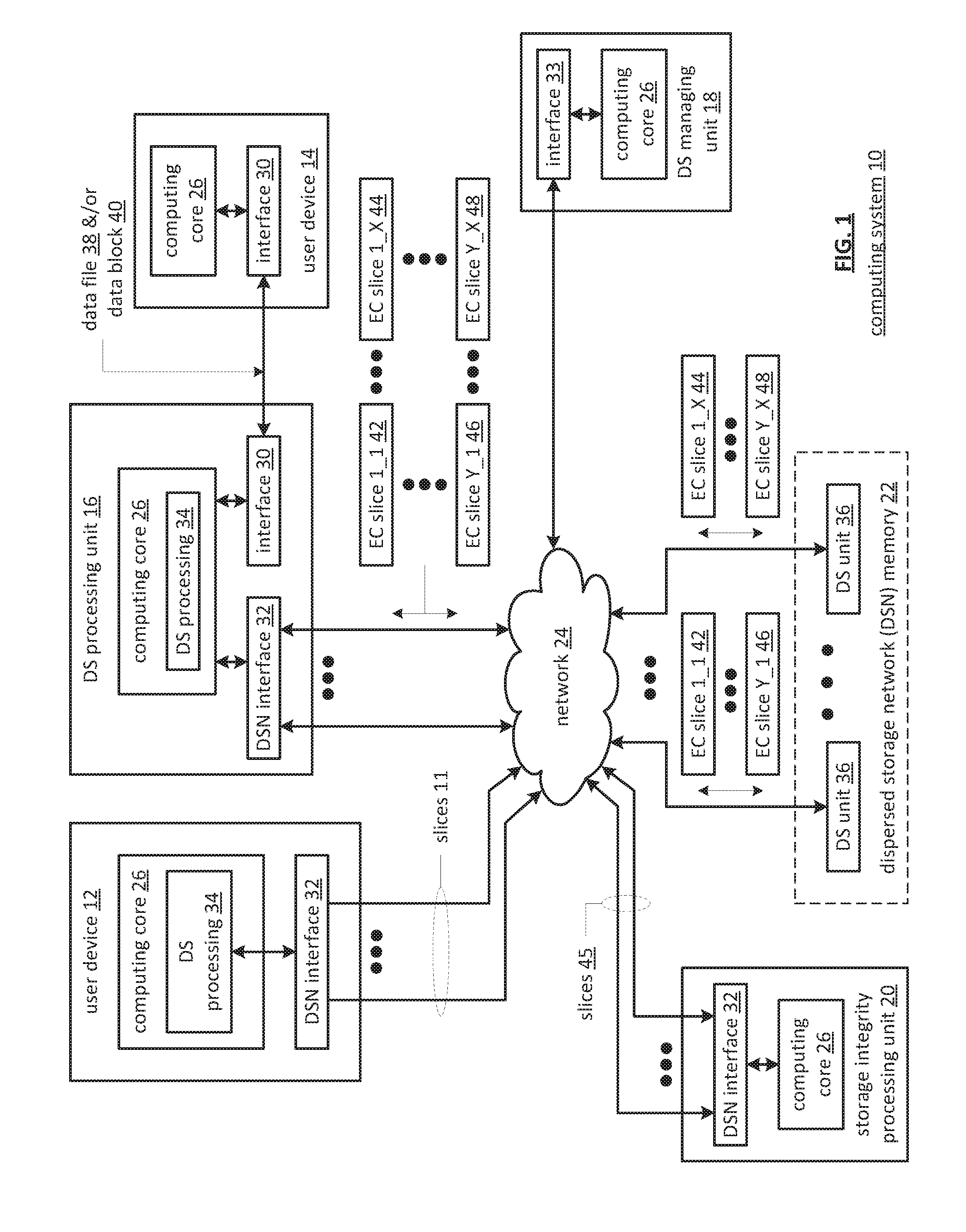
FIG. 1 is a schematic block diagram of a computing system 10 that includes one or more of a first type of user devices 12, one or more of a second type of user devices 14, at least one distributed storage (DS) processing unit 16, at least one DS managing unit 18, at least one storage integrity processing unit 20, and a distributed/dispersed storage network (DSN) memory 22 coupled via a network 24. The network 24 may include one or more wireless and/or wire lined communication systems; one or more private intranet systems and/or public internet systems; and/or one or more local area networks (LAN) and/or wide area networks (WAN).
The DSN memory 22 includes a plurality of distributed storage (DS) units 36 for storing data of the system. Each of the DS units 36 includes a processing module and memory and may be located at a geographically different site than the other DS units (e.g., one in Chicago, one in Milwaukee, etc.). The processing module may be a single processing device or a plurality of processing devices. Such a processing device may be a microprocessor, micro-controller, digital signal processor, microcomputer, central processing unit, field programmable gate array, programmable logic device, state machine, logic circuitry, analog circuitry, digital circuitry, and/or any device that manipulates signals (analog and/or digital) based on hard coding of the circuitry and/or operational instructions. The processing module may have an associated memory and/or memory element, which may be a single memory device, a plurality of memory devices, and/or embedded circuitry of the processing module. Such a memory device may be a read-only memory, random access memory, volatile memory, non-volatile memory, static memory, dynamic memory, flash memory, cache memory, and/or any device that stores digital information. Note that if the processing module includes more than one processing device, the processing devices may be centrally located (e.g., directly coupled together via a wired and/or wireless bus structure) or may be distributedly located (e.g., cloud computing via indirect coupling via a local area network and/or a wide area network). Further note that when the processing module implements one or more of its functions via a state machine, analog circuitry, digital circuitry, and/or logic circuitry, the memory and/or memory element storing the corresponding operational instructions may be embedded within, or external to, the circuitry comprising the state machine, analog circuitry, digital circuitry, and/or logic circuitry. Still further note that, the memory element stores, and the processing module executes, hard coded and/or operational instructions corresponding to at least some of the steps and/or functions illustrated in FIGS. 1-10.
Each of the user devices 12-14, the DS processing unit 16, the DS managing unit 18, and the storage integrity processing unit 20 may be a portable computing device (e.g., a social networking device, a gaming device, a cell phone, a smart phone, a personal digital assistant, a digital music player, a digital video player, a laptop computer, a handheld computer, a video game controller, and/or any other portable device that includes a computing core) and/or a fixed computing device (e.g., a personal computer, a computer server, a cable set-top box, a satellite receiver, a television set, a printer, a fax machine, home entertainment equipment, a video game console, and/or any type of home or office computing equipment). Such a portable or fixed computing device includes a computing core 26 and one or more interfaces 30, 32, and/or 33. An embodiment of the computing core 26 will be described with reference to FIG. 2.
With respect to the interfaces, each of the interfaces 30, 32, and 33 includes software and/or hardware to support one or more communication links via the network 24 and/or directly. For example, interfaces 30 support a communication link (wired, wireless, direct, via a LAN, via the network 24, etc.) between the first type of user device 14 and the DS processing unit 16. As another example, DSN interface 32 supports a plurality of communication links via the network 24 between the DSN memory 22 and the DS processing unit 16, the first type of user device 12, and/or the storage integrity processing unit 20. As yet another example, interface 33 supports a communication link between the DS managing unit 18 and any one of the other devices and/or units 12, 14, 16, 20, and/or 22 via the network 24.
In general, and with respect to data storage, the system 10 supports three primary functions: distributed network data storage management, distributed data storage and retrieval, and data storage integrity verification. In accordance with these three primary functions, data can be distributedly stored in a plurality of physically different locations and subsequently retrieved in a reliable and secure manner regardless of failures of individual storage devices, failures of network equipment, the duration of storage, the amount of data being stored, attempts at hacking the data, etc.
The DS managing unit 18 performs distributed network data storage management functions, which include establishing distributed data storage parameters, performing network operations, performing network administration, and/or performing network maintenance. The DS managing unit 18 establishes the distributed data storage parameters (e.g., allocation of virtual DSN memory space, distributed storage parameters, security parameters, billing information, user profile information, etc.) for one or more of the user devices 12-14 (e.g., established for individual devices, established for a user group of devices, established for public access by the user devices, etc.). For example, the DS managing unit 18 coordinates the creation of a vault (e.g., a virtual memory block) within the DSN memory 22 for a user device (for a group of devices, or for public access). The DS managing unit 18 also determines the distributed data storage parameters for the vault. In particular, the DS managing unit 18 determines a number of slices (e.g., the number that a data segment of a data file and/or data block is partitioned into for distributed storage) and a read threshold value (e.g., the minimum number of slices required to reconstruct the data segment).
As another example, the DS managing module 18 creates and stores, locally or within the DSN memory 22, user profile information. The user profile information includes one or more of authentication information, permissions, and/or the security parameters. The security parameters may include one or more of encryption/decryption scheme, one or more encryption keys, key generation scheme, and data encoding/decoding scheme.
As yet another example, the DS managing unit 18 creates billing information for a particular user, user group, vault access, public vault access, etc. For instance, the DS managing unit 18 tracks the number of times user accesses a private vault and/or public vaults, which can be used to generate a per-access bill. In another instance, the DS managing unit 18 tracks the amount of data stored and/or retrieved by a user device and/or a user group, which can be used to generate a per-data-amount bill.
The DS managing unit 18 also performs network operations, network administration, and/or network maintenance. As at least part of performing the network operations and/or administration, the DS managing unit 18 monitors performance of the devices and/or units of the system 10 for potential failures, determines the devices' and/or units' activation status, determines the devices' and/or units' loading, and any other system level operation that affects the performance level of the system 10. For example, the DS managing unit 18 receives and aggregates network management alarms, alerts, errors, status information, performance information, and messages from the devices 12-14 and/or the units 16, 20, 22. For example, the DS managing unit 18 receives a simple network management protocol (SNMP) message regarding the status of the DS processing unit 16.
The DS managing unit 18 performs the network maintenance by identifying equipment within the system 10 that needs replacing, upgrading, repairing, and/or expanding. For example, the DS managing unit 18 determines that the DSN memory 22 needs more DS units 36 or that one or more of the DS units 36 needs updating.
The second primary function (i.e., distributed data storage and retrieval) begins and ends with a user device 12-14. For instance, if a second type of user device 14 has a data file 38 and/or data block 40 to store in the DSN memory 22, it sends the data file 38 and/or data block 40 to the DS processing unit 16 via its interface 30. As will be described in greater detail with reference to FIG. 2, the interface 30 functions to mimic a conventional operating system (OS) file system interface (e.g., network file system (NFS), flash file system (FFS), disk file system (DFS), file transfer protocol (FTP), web-based distributed authoring and versioning (WebDAV), etc.) and/or a block memory interface (e.g., small computer system interface (SCSI), internet small computer system interface (iSCSI), etc.). In addition, the interface 30 may attach a user identification code (ID) to the data file 38 and/or data block 40.
The DS processing unit 16 receives the data file 38 and/or data block 40 via its interface 30 and performs a distributed storage (DS) process 34 thereon (e.g., an error coding dispersal storage function). The DS processing 34 begins by partitioning the data file 38 and/or data block 40 into one or more data segments, which is represented as Y data segments. For example, the DS processing 34 may partition the data file 38 and/or data block 40 into a fixed byte size segment (e.g., 2.sup.1 to 2.sup.n bytes, where n=>2) or a variable byte size (e.g., change byte size from segment to segment, or from groups of segments to groups of segments, etc.).
For each of the Y data segments, the DS processing 34 error encodes (e.g., forward error correction (FEC), information dispersal algorithm, or error correction coding) and slices (or slices then error encodes) the data segment into a plurality of error coded (EC) data slices 42-48, which is represented as X slices per data segment. The number of slices (X) per segment, which corresponds to a number of pillars n, is set in accordance with the distributed data storage parameters and the error coding scheme. For example, if a Reed-Solomon (or other FEC scheme) is used in an n/k system, then a data segment is divided into n slices, where k number of slices is needed to reconstruct the original data (i.e., k is the threshold). As a few specific examples, the n/k factor may be 5/3; 6/4; 8/6; 8/5; 16/10.
For each EC slice 42-48, the DS processing unit 16 creates a unique slice name and appends it to the corresponding slice 42-48. The slice name includes universal DSN memory addressing routing information (e.g., virtual memory addresses in the DSN memory 22) and user-specific information (e.g., user ID, file name, data block identifier, etc.).
The DS processing unit 16 transmits the plurality of EC slices 42-48 to a plurality of DS units 36 of the DSN memory 22 via the DSN interface 32 and the network 24. The DSN interface 32 formats each of the slices for transmission via the network 24. For example, the DSN interface 32 may utilize an internet protocol (e.g., TCP/IP, etc.) to packetize the EC slices 42-48 for transmission via the network 24.
The number of DS units 36 receiving the EC slices 42-48 is dependent on the distributed data storage parameters established by the DS managing unit 18. For example, the DS managing unit 18 may indicate that each slice is to be stored in a different DS unit 36. As another example, the DS managing unit 18 may indicate that like slice numbers of different data segments are to be stored in the same DS unit 36. For example, the first slice of each of the data segments is to be stored in a first DS unit 36, the second slice of each of the data segments is to be stored in a second DS unit 36, etc. In this manner, the data is encoded and distributedly stored at physically diverse locations to improve data storage integrity and security. Further examples of encoding the data segments will be provided with reference to one or more of FIGS. 2-10.
Each DS unit 36 that receives an EC slice 42-48 for storage translates the virtual DSN memory address of the slice into a local physical address for storage. Accordingly, each DS unit 36 maintains a virtual to physical memory mapping to assist in the storage and retrieval of data.
The first type of user device 12 performs a similar function to store data in the DSN memory 22 with the exception that it includes the DS processing. As such, the device 12 encodes and slices the data file and/or data block it has to store. The device then transmits the slices 11 to the DSN memory via its DSN interface 32 and the network 24.
For a second type of user device 14 to retrieve a data file or data block from memory, it issues a read command via its interface 30 to the DS processing unit 16. The DS processing unit 16 performs the DS processing 34 to identify the DS units 36 storing the slices of the data file and/or data block based on the read command. The DS processing unit 16 may also communicate with the DS managing unit 18 to verify that the user device 14 is authorized to access the requested data.
Assuming that the user device is authorized to access the requested data, the DS processing unit 16 issues slice read commands to at least a threshold number of the DS units 36 storing the requested data (e.g., to at least 10 DS units for a 16/10 error coding scheme). Each of the DS units 36 receiving the slice read command, verifies the command, accesses its virtual to physical memory mapping, retrieves the requested slice, or slices, and transmits it to the DS processing unit 16.
Once the DS processing unit 16 has received a read threshold number of slices for a data segment, it performs an error decoding function and de-slicing to reconstruct the data segment. When Y number of data segments has been reconstructed, the DS processing unit 16 provides the data file 38 and/or data block 40 to the user device 14. Note that the first type of user device 12 performs a similar process to retrieve a data file and/or data block.
The storage integrity processing unit 20 performs the third primary function of data storage integrity verification. In general, the storage integrity processing unit 20 periodically retrieves slices 45, and/or slice names, of a data file or data block of a user device to verify that one or more slices have not been corrupted or lost (e.g., the DS unit failed). The retrieval process mimics the read process previously described.
If the storage integrity processing unit 20 determines that one or more slices is corrupted or lost, it rebuilds the corrupted or lost slice(s) in accordance with the error coding scheme. The storage integrity processing unit 20 stores the rebuild slice, or slices, in the appropriate DS unit(s) 36 in a manner that mimics the write process previously described.
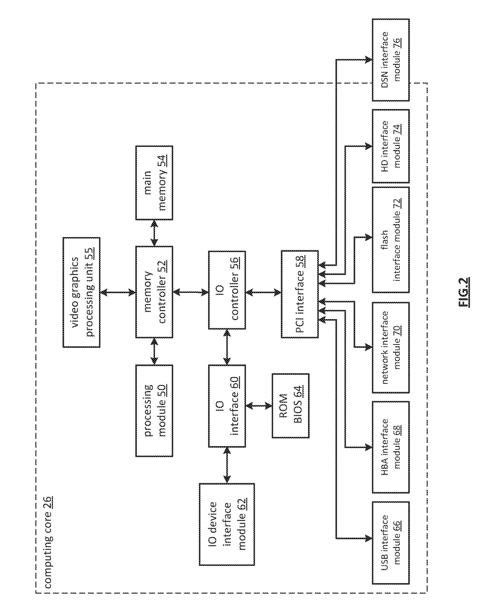
FIG. 2 is a schematic block diagram of an embodiment of a computing core 26 that includes a processing module 50, a memory controller 52, main memory 54, a video graphics processing unit 55, an input/output (IO) controller 56, a peripheral component interconnect (PCI) interface 58, an IO interface 60, at least one IO device interface module 62, a read only memory (ROM) basic input output system (BIOS) 64, and one or more memory interface modules. The memory interface module(s) includes one or more of a universal serial bus (USB) interface module 66, a host bus adapter (HBA) interface module 68, a network interface module 70, a flash interface module 72, a hard drive interface module 74, and a DSN interface module 76. Note the DSN interface module 76 and/or the network interface module 70 may function as the interface 30 of the user device 14 of FIG. 1. Further note that the IO device interface module 62 and/or the memory interface modules may be collectively or individually referred to as IO ports.
The processing module 50 may be a single processing device or a plurality of processing devices. Such a processing device may be a microprocessor, micro-controller, digital signal processor, microcomputer, central processing unit, field programmable gate array, programmable logic device, state machine, logic circuitry, analog circuitry, digital circuitry, and/or any device that manipulates signals (analog and/or digital) based on hard coding of the circuitry and/or operational instructions. The processing module 50 may have an associated memory and/or memory element, which may be a single memory device, a plurality of memory devices, and/or embedded circuitry of the processing module 50. Such a memory device may be a read-only memory, random access memory, volatile memory, non-volatile memory, static memory, dynamic memory, flash memory, cache memory, and/or any device that stores digital information. Note that if the processing module 50 includes more than one processing device, the processing devices may be centrally located (e.g., directly coupled together via a wired and/or wireless bus structure) or may be distributedly located (e.g., cloud computing via indirect coupling via a local area network and/or a wide area network). Further note that when the processing module 50 implements one or more of its functions via a state machine, analog circuitry, digital circuitry, and/or logic circuitry, the memory and/or memory element storing the corresponding operational instructions may be embedded within, or external to, the circuitry comprising the state machine, analog circuitry, digital circuitry, and/or logic circuitry. Still further note that, the memory element stores, and the processing module 50 executes, hard coded and/or operational instructions corresponding to at least some of the steps and/or functions illustrated in FIGS. 1-10.
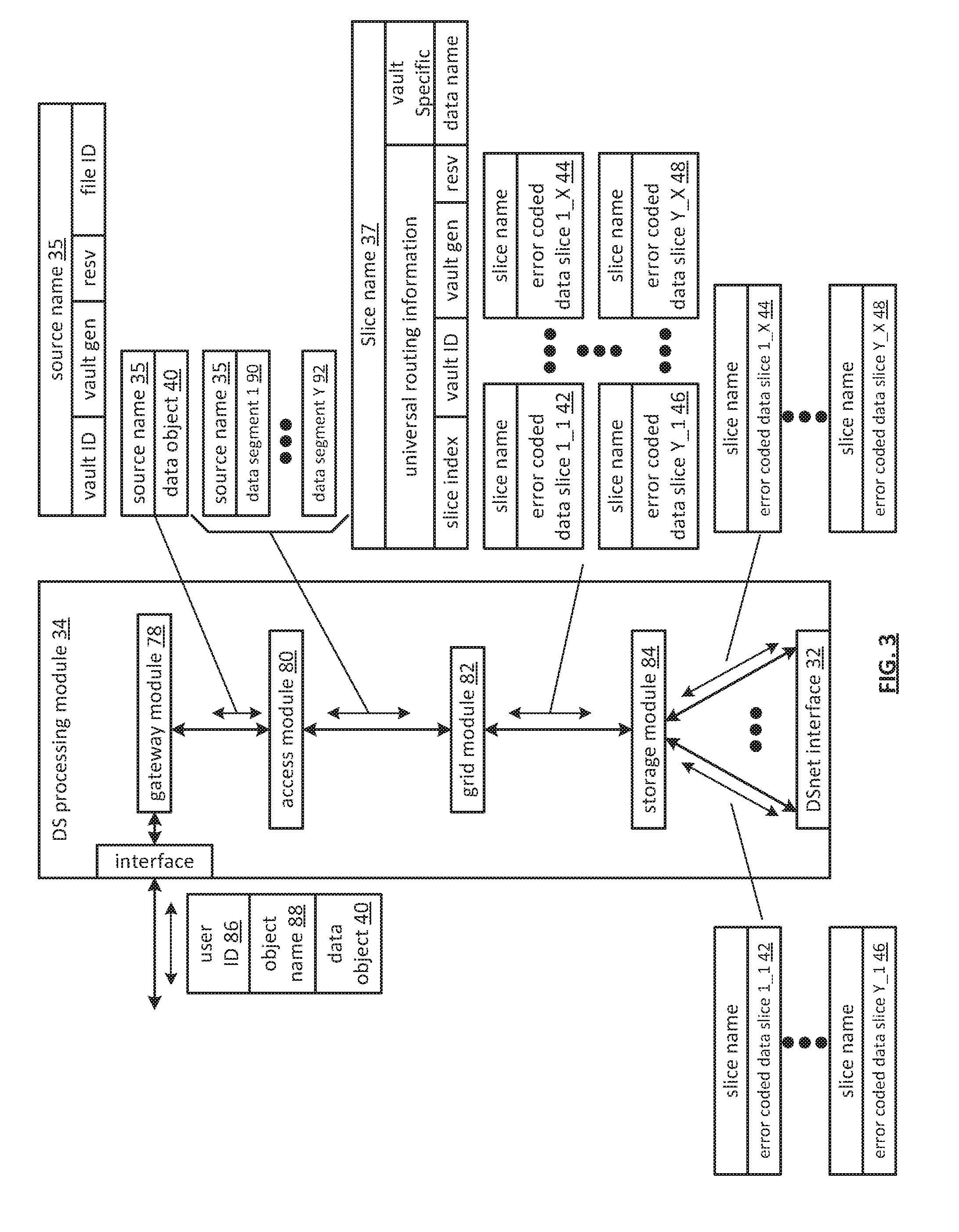
FIG. 3 is a schematic block diagram of an embodiment of a dispersed storage (DS) processing module 34 of user device 12 and/or of the DS processing unit 16. The DS processing module 34 includes a gateway module 78, an access module 80, a grid module 82, and a storage module 84. The DS processing module 34 may also include an interface 30 and the DSnet interface 32 or the interfaces 68 and/or 70 may be part of user device 12 or of the DS processing unit 16. The DS processing module 34 may further include a bypass/feedback path between the storage module 84 to the gateway module 78. Note that the modules 78-84 of the DS processing module 34 may be in a single unit or distributed across multiple units.
In an example of storing data, the gateway module 78 receives an incoming data object that includes a user ID field 86, an object name field 88, and the data object field 40 and may also receive corresponding information that includes a process identifier (e.g., an internal process/application ID), metadata, a file system directory, a block number, a transaction message, a user device identity (ID), a data object identifier, a source name, and/or user information. The gateway module 78 authenticates the user associated with the data object by verifying the user ID 86 with the managing unit 18 and/or another authenticating unit.
When the user is authenticated, the gateway module 78 obtains user information from the management unit 18, the user device, and/or the other authenticating unit. The user information includes a vault identifier, operational parameters, and user attributes (e.g., user data, billing information, etc.). A vault identifier identifies a vault, which is a virtual memory space that maps to a set of DS storage units 36. For example, vault 1 (i.e., user 1's DSN memory space) includes eight DS storage units (X=8 wide) and vault 2 (i.e., user 2's DSN memory space) includes sixteen DS storage units (X=16 wide). The operational parameters may include an error coding algorithm, the width n (number of pillars X or slices per segment for this vault), a read threshold T, a write threshold, an encryption algorithm, a slicing parameter, a compression algorithm, an integrity check method, caching settings, parallelism settings, and/or other parameters that may be used to access the DSN memory layer.
The gateway module 78 uses the user information to assign a source name 35 to the data. For instance, the gateway module 78 determines the source name 35 of the data object 40 based on the vault identifier and the data object. For example, the source name may contain a file identifier (ID), a vault generation number, a reserved field, and a vault identifier (ID). As another example, the gateway module 78 may generate the file ID based on a hash function of the data object 40. Note that the gateway module 78 may also perform message conversion, protocol conversion, electrical conversion, optical conversion, access control, user identification, user information retrieval, traffic monitoring, statistics generation, configuration, management, and/or source name determination.
The access module 80 receives the data object 40 and creates a series of data segments 1 through Y 90-92 in accordance with a data storage protocol (e.g., file storage system, a block storage system, and/or an aggregated block storage system). The number of segments Y may be chosen or randomly assigned based on a selected segment size and the size of the data object. For example, if the number of segments is chosen to be a fixed number, then the size of the segments varies as a function of the size of the data object. For instance, if the data object is an image file of 4,194,304 eight bit bytes (e.g., 33,554,432 bits) and the number of segments Y=131,072, then each segment is 256 bits or 32 bytes. As another example, if segment sized is fixed, then the number of segments Y varies based on the size of data object. For instance, if the data object is an image file of 4,194,304 bytes and the fixed size of each segment is 4,096 bytes, then the number of segments Y=1,024. Note that each segment is associated with the same source name.
The grid module 82 receives the data segments and may manipulate (e.g., compression, encryption, cyclic redundancy check (CRC), etc.) each of the data segments before performing an error coding function of the error coding dispersal storage function to produce a pre-manipulated data segment. After manipulating a data segment, if applicable, the grid module 82 error encodes (e.g., Reed-Solomon, Convolution encoding, Trellis encoding, etc.) the data segment or manipulated data segment into X error coded data slices 42-44.
The value X, or the number of pillars (e.g., X=16), is chosen as a parameter of the error coding dispersal storage function. Other parameters of the error coding dispersal function include a read threshold T, a write threshold W, etc. The read threshold (e.g., T=10, when X=16) corresponds to the minimum number of error-free error coded data slices required to reconstruct the data segment. In other words, the DS processing module 34 can compensate for X-T (e.g., 16-10=6) missing error coded data slices per data segment. The write threshold W corresponds to a minimum number of DS storage units that acknowledge proper storage of their respective data slices before the DS processing module indicates proper storage of the encoded data segment. Note that the write threshold is greater than or equal to the read threshold for a given number of pillars (X).
For each data slice of a data segment, the grid module 82 generates a unique slice name 37 and attaches it thereto. The slice name 37 includes a universal routing information field and a vault specific field and may be 48 bytes (e.g., 24 bytes for each of the universal routing information field and the vault specific field). As illustrated, the universal routing information field includes a slice index, a vault ID, a vault generation, and a reserved field. The slice index is based on the pillar number and the vault ID and, as such, is unique for each pillar (e.g., slices of the same pillar for the same vault for any segment will share the same slice index). The vault specific field includes a data name, which includes a file ID and a segment number (e.g., a sequential numbering of data segments 1-Y of a simple data object or a data block number).
Prior to outputting the error coded data slices of a data segment, the grid module may perform post-slice manipulation on the slices. If enabled, the manipulation includes slice level compression, encryption, CRC, addressing, tagging, and/or other manipulation to improve the effectiveness of the computing system.
When the error coded data slices of a data segment are ready to be outputted, the grid module 82 determines which of the DS storage units 36 will store the EC data slices based on a dispersed storage memory mapping associated with the user's vault and/or DS storage unit attributes. The DS storage unit attributes may include availability, self-selection, performance history, link speed, link latency, ownership, available DSN memory, domain, cost, a prioritization scheme, a centralized selection message from another source, a lookup table, data ownership, and/or any other factor to optimize the operation of the computing system. Note that the number of DS storage units 36 is equal to or greater than the number of pillars (e.g., X) so that no more than one error coded data slice of the same data segment is stored on the same DS storage unit 36. Further note that EC data slices of the same pillar number but of different segments (e.g., EC data slice 1 of data segment 1 and EC data slice 1 of data segment 2) may be stored on the same or different DS storage units 36.
The storage module 84 performs an integrity check on the outbound encoded data slices and, when successful, identifies a plurality of DS storage units based on information provided by the grid module 82. The storage module 84 then outputs the encoded data slices 1 through X of each segment 1 through Y to the DS storage units 36. Each of the DS storage units 36 stores its EC data slice(s) and maintains a local virtual DSN address to physical location table to convert the virtual DSN address of the EC data slice(s) into physical storage addresses.
In an example of a read operation, the user device 12 and/or 14 sends a read request to the DS processing unit 16, which authenticates the request. When the request is authentic, the DS processing unit 16 sends a read message to each of the DS storage units 36 storing slices of the data object being read. The slices are received via the DSnet interface 32 and processed by the storage module 84, which performs a parity check and provides the slices to the grid module 82 when the parity check was successful. The grid module 82 decodes the slices in accordance with the error coding dispersal storage function to reconstruct the data segment. The access module 80 reconstructs the data object from the data segments and the gateway module 78 formats the data object for transmission to the user device.
FIG. 4 is a schematic block diagram of an embodiment of a grid module 82 that includes a control unit 73, a pre-slice manipulator 75, an encoder 77, a slicer 79, a post-slice manipulator 81, a pre-slice de-manipulator 83, a decoder 85, a de-slicer 87, and/or a post-slice de-manipulator 89. Note that the control unit 73 may be partially or completely external to the grid module 82. For example, the control unit 73 may be part of the computing core at a remote location, part of a user device, part of the DS managing unit 18, or distributed amongst one or more DS storage units.
In an example of write operation, the pre-slice manipulator 75 receives a data segment 90-92 and a write instruction from an authorized user device. The pre-slice manipulator 75 determines if pre-manipulation of the data segment 90-92 is required and, if so, what type. The pre-slice manipulator 75 may make the determination independently or based on instructions from the control unit 73, where the determination is based on a computing system-wide predetermination, a table lookup, vault parameters associated with the user identification, the type of data, security requirements, available DSN memory, performance requirements, and/or other metadata.
Once a positive determination is made, the pre-slice manipulator 75 manipulates the data segment 90-92 in accordance with the type of manipulation. For example, the type of manipulation may be compression (e.g., Lempel-Ziv-Welch, Huffman, Golomb, fractal, wavelet, etc.), signatures (e.g., Digital Signature Algorithm (DSA), Elliptic Curve DSA, Secure Hash Algorithm, etc.), watermarking, tagging, encryption (e.g., Data Encryption Standard, Advanced Encryption Standard, etc.), adding metadata (e.g., time/date stamping, user information, file type, etc.), cyclic redundancy check (e.g., CRC32), and/or other data manipulations to produce the pre-manipulated data segment.
The encoder 77 encodes the pre-manipulated data segment 92 using a forward error correction (FEC) encoder (and/or other type of erasure coding and/or error coding) to produce an encoded data segment 94. The encoder 77 determines which forward error correction algorithm to use based on a predetermination associated with the user's vault, a time based algorithm, user direction, DS managing unit direction, control unit direction, as a function of the data type, as a function of the data segment 92 metadata, and/or any other factor to determine algorithm type. The forward error correction algorithm may be Golay, Multidimensional parity, Reed-Solomon, Hamming, Bose Ray Chauduri Hocquenghem (BCH), Cauchy-Reed-Solomon, or any other FEC encoder. Note that the encoder 77 may use a different encoding algorithm for each data segment 92, the same encoding algorithm for the data segments 92 of a data object, or a combination thereof.
The encoded data segment 94 is of greater size than the data segment 92 by the overhead rate of the encoding algorithm by a factor of X/T, where X is the width or number of slices, and T is the read threshold. In this regard, the corresponding decoding process can accommodate at most X-T missing EC data slices and still recreate the data segment 92. For example, if X=16 and T=10, then the data segment 92 will be recoverable as long as 10 or more EC data slices per segment are not corrupted.
The slicer 79 transforms the encoded data segment 94 into EC data slices in accordance with the slicing parameter from the vault for this user and/or data segment 92. For example, if the slicing parameter is X=16, then the slicer 79 slices each encoded data segment 94 into 16 encoded slices.
The post-slice manipulator 81 performs, if enabled, post-manipulation on the encoded slices to produce the EC data slices. If enabled, the post-slice manipulator 81 determines the type of post-manipulation, which may be based on a computing system-wide predetermination, parameters in the vault for this user, a table lookup, the user identification, the type of data, security requirements, available DSN memory, performance requirements, control unit directed, and/or other metadata. Note that the type of post-slice manipulation may include slice level compression, signatures, encryption, CRC, addressing, watermarking, tagging, adding metadata, and/or other manipulation to improve the effectiveness of the computing system.
In an example of a read operation, the post-slice de-manipulator 89 receives at least a read threshold number of EC data slices and performs the inverse function of the post-slice manipulator 81 to produce a plurality of encoded slices. The de-slicer 87 de-slices the encoded slices to produce an encoded data segment 94. The decoder 85 performs the inverse function of the encoder 77 to recapture the data segment 90-92. The pre-slice de-manipulator 83 performs the inverse function of the pre-slice manipulator 75 to recapture the data segment 90-92.
FIG. 5 is a diagram of an example of slicing an encoded data segment 94 by the slicer 79. In this example, the encoded data segment 94 includes thirty-two bits, but may include more or less bits. The slicer 79 disperses the bits of the encoded data segment 94 across the EC data slices in a pattern as shown. As such, each EC data slice does not include consecutive bits of the data segment 94 reducing the impact of consecutive bit failures on data recovery. For example, if EC data slice 2 (which includes bits 1, 5, 9, 13, 17, 25, and 29) is unavailable (e.g., lost, inaccessible, or corrupted), the data segment can be reconstructed from the other EC data slices (e.g., 1, 3 and 4 for a read threshold of 3 and a width of 4).
FIG. 6A is a schematic block diagram of an embodiment of a communication system. The system includes a sending dispersed storage (DS) processing unit 102, a network 24, and a receiving DS processing unit 104. In an implementation example, the sending DS processing unit 102 and the receiving DS processing unit 104 include a DS processing module 34. The sending DS processing unit 102 and the receiving DS processing unit 104 operate to communicate data 106. In an example of operation, the sending DS processing unit 102 obtains data 106 for transmission to the receiving DS processing unit 104. The data may include a plurality of data portions a-c. Next, sending DS processing unit 102 generates a plurality of sets of error coding dispersal storage function parameters to utilize in the generation of a plurality of sets of encoded data slices which achieves communications goals for each of the corresponding data portions a-c. For instance, a reliability goal for data portion a may be greater than a reliability goal for data portion b when receiving data portion a by the receiving DS processing unit 104 is a higher priority than receiving data portion b. Next, the sending DS processing unit 102 dispersed storage error encodes each data portion of the plurality of data portions a-c in accordance with a corresponding set of error coding dispersal storage function parameters of the plurality of sets of error coding dispersal storage function parameters to produce a plurality of sets of encoded data slices as slice sets a-c. For instance, a plurality of sets of encoded data slices corresponds to each of the three portions. For each data portion, each set of a corresponding plurality of sets of encoded data slices includes at least a decode threshold number of encoded data slices and at most a pillar width a number of encoded data slices in accordance with the communications goals. For example, the DS processing unit 102 generates a pillar width number of 32 encoded data slices to obtain a communication goal of oversampling when a decode threshold is 10 and receiving a decode threshold number of encoded data slices meets a minimum reliability communication goal.
In the example of operation continued, the sending DS processing unit 102 sends the plurality of sets of encoded data slices a-c to the receiving DS processing unit 104 via the network 24. The receiving DS processing unit 104 receives the plurality of sets of encoded data slices as receive slice sets a-c. The receive slice sets a-c may introduce slice errors as compared to slice sets a-c when network 24 experiences errors and outages. The receiving DS processing unit 104 receives the receive slice sets a-c which may include at least some slices of the encoded data slice sets a-c as sent by the sending DS processing unit 102. The receiving DS processing unit 104 dispersed storage error decodes each set of the received slices sets a-c utilizing corresponding parameters of the plurality of sets of error coding dispersal storage function parameters to reproduce data portions a-c. The receiving DS processing unit 104 aggregates the data portions a-c to reproduce the data 106.
In an instance, the receiving DS processing unit 104 successfully reproduces the data portions a-c with no errors. As another instance, the receiving DS processing unit 104 successfully reproduces less than all of the data portions a-c, wherein the receiving DS processing unit 104 fills in missing portions of one or more of the data portions a-c to produce a modified version of the data 106. For instance, the receiving DS processing unit 104 successfully reproduces data portions a and b but not data portion c. The receiving DS processing unit 104 substitutes filler bits for data portions c to produce a synthesized data portion c. The receiving DS processing unit 104 aggregates data portions a-b and the synthesized data portions c to produce a modified version of the data 106.
FIG. 6B is a table illustrating an example of a data partition 108. The data partition 108 includes a plurality of data bytes 1-X organized by a most significant bit field (e.g., six bits), a middle bit field (e.g., five bits), and a least significant bit field (e.g., five bits). For example, an audio file includes a plurality of data bytes 1-X representing 16-bit audio sampling bytes. As such, most significant bits are more important than least significant bits in a subsequent decoding process to produce a reproduced audio file that is as close as possible (e.g., with minimal distortion) to an original audio file. The three fields are associated with three data portions. For example, a data portion "a" includes the most significant bit field, wherein the most significant six bits of each of the plurality of bytes 1-X is included in data portion a. A data portion b includes the middle bit field, wherein the middle five bits of each of the plurality of bytes 1-X are included in data portion b. A data portion c includes the least significant bit field, wherein the significant five bits of each of the plurality of bytes 1-X is included in data portion c.
Note that the data portion a may be more important than the data portions c in the reproduction of the audio file. A sending dispersed storage (DS) processing unit may select three sets of error coding dispersal storage function parameters to dispersed storage error encode each of the data portions a-c to achieve one or more system goals. System goals may include one or more of reliability, speed of transmission, latency, availability, complexity, and simplicity. For example, the sending DS processing unit selects a first set of error coding dispersal storage function parameters that align with high reliability to dispersed storage error encode the data portion a. For instance, the sending DS processing unit selects the first set of parameters that include a pillar width of 15 and a decode threshold of 8. As another example, the sending DS processing unit selects a second set of error coding dispersal storage function parameters that align with more efficiency to dispersed storage error encode the data portion b. For instance, the sending DS processing unit selects the second set of parameters to include a pillar width of 12 and a decode threshold of 8. As yet another example, the sending DS processing unit selects a third set of error coding dispersal storage function parameters that align with even more efficiency to dispersed storage error encode the data portion c. For instance, the sending DS processing unit selects the third set of parameters that include a pillar width of 10 and a decode threshold of 8.
FIG. 7A is a flowchart illustrating an example of sending data. The method begins with step 110 where a processing module (e.g., of a sending dispersed storage (DS) processing unit) obtains data for transmission. The data may include an analog or digital representation of any one of data content, media content, video, audio, speech, word processing files, financial records, software, etc. The method continues at step 112 where the processing module partitions the data in accordance with a data partitioning scheme to produce a plurality of data portions. The processing module selects the data partitioning scheme by at least one of selecting the data partitioning scheme by determining a data characterization based on at least one of a data analysis (e.g., determine type of data such as video, audio, etc.), received data characterization information, a predetermination, a message, a look up, and a comparison of the data to other characterized data and selecting the data partitioning scheme based on at least one of the data characterization, a lookup, a partitioning policy, a predetermination, a message, and a previous data partitioning approach.
The partitioning the data includes partitioning the data into a first data portion and a second data portion, wherein the first data portion includes higher priority content of the data than the second data portion. For example, the processing module partitions the data into a first data portion that includes a most significant six bits of each byte of a plurality of bytes of the data and into a second portion that include a least significant 10 bits of each byte of the plurality of bytes of the data when each byte of the plurality of bytes includes a 16-bit audio sample. As another example, the processing module partitions the data into a first data portion that includes a base frame set of bytes of a plurality of bytes of the data and into a change frame set of bytes of the plurality of bytes of the data when the data includes compressed video.
The method continues at step 114 where the processing module dispersed storage error encodes the plurality of data portions using a plurality of sets of error coding dispersal storage function parameters to produce a plurality of sets of encoded data slices. The processing module selects the plurality of sets of error coding dispersal storage function parameters by at least one of selecting the plurality of sets of error coding dispersal storage function parameters by determining a data characterization based on at least one of a data analysis, received data characterization information, a predetermination, a message, a look up, a comparison of the data to other characterized data, and the data partitioning approach and selecting the plurality of sets of error coding dispersal storage function parameters based on at least one of the data characterization, the data partitioning approach, a reliability requirement, a performance requirement, a lookup, a data encoding policy, a predetermination, a message, and a previous data encoding approach.
For example, the processing module selects a set of error coding dispersal storage function parameters to generate a set of the plurality of sets of encoded data slices to include just a decode threshold number of encoded data slices when a received data characterization indicates that only a decode threshold number of encoded data slices are required to meet a reliability requirement. As another example, the processing module selects the set of error coding dispersal storage function parameters to generate the set of the plurality of sets of encoded data slices to include a pillar width minus 2 number of encoded data slices when the received data characterization indicates that mild oversampling is required to meet a performance requirement. For instance, the processing module utilizes oversampling when performance of a network connection between the sending DS processing unit and a receiving DS processing unit deteriorates while transmitting the data.
The method continues at step 116 where the processing module outputs the plurality of sets of encoded data slices. For sample, the processing module sends the plurality of sets of encoded data slices to the receiving DS processing unit via a network. The method continues at step 118 where the processing module provides an indication of the data partitioning scheme and the plurality of sets of error coding dispersal storage function parameters to a receiving entity. For example, the processing module sends the data partitioning scheme and the plurality of sets of error coding dispersal storage function parameters to the receiving DS processing unit. As another example, the processing module sends the data partitioning scheme and the plurality of sets of error coding dispersal storage function parameters to a dispersed storage network (DSN) for storage therein and subsequent retrieval by the receiving DS processing unit.
FIG. 7B is a flowchart illustrating an example of receiving data, wherein the data has been encoded into a plurality of sets of encoded data slices using a plurality of sets of error coding dispersal storage function parameters and a data partitioning scheme. The method begins with step 120 where a processing module (e.g., of a receiving dispersed storage (DS) processing unit) receives an indication of the data partitioning scheme and the plurality of sets of error coding dispersal storage function parameters from a transmitting entity. For example, the processing module receives a message from a sending DS processing unit, wherein the message includes the indication of the data partitioning scheme and the plurality of sets of error coding dispersal storage function parameters. As another example, the processing module retrieves the indication of the data partitioning scheme and the plurality of sets of error coding dispersal storage function parameters from a dispersed storage network (DSN) memory.
The method continues at step 122 where the processing module receives, via a network, at least a decode threshold number of encoded data slices for each set of the plurality of sets of encoded data slices. The receiving the at least a decode threshold number of encoded data slices includes determining whether an encoded data slice of the at least a decode threshold number of encoded data slices includes a bit error. The processing module discards the encoded data slice from the at least a decode threshold number of encoded data slices to produce an updated set of encoded data slices when the encoded data slice includes the bit error. Next, the processing module determines whether the updated set of encoded data slices includes at least a decodable number of encoded data slices. The processing module dispersed storage error decodes the at least a decode threshold number of encoded data slices including disperse storage error decoding the updated set of encoded data slices when the updated set of encoded data slices includes at least a decodable number of encoded data slices. The processing module utilizes data filler (e.g., bits of all zeros, bits of all ones) for the corresponding data portion when the updated set of encoded data slices does not include at least a decodable number of encoded data slices.
The method continues at step 124 with a processing module dispersed storage error decodes the at least a decode threshold number of encoded data slices, for each set of the plurality of sets of encoded data slices, using a corresponding one of the plurality of sets of error coding dispersal storage function parameters to produce a decoded data portion. The method continues at step 126 where the processing module recaptures the data from a plurality of decoded data portions in accordance with the data partitioning scheme. For example, the processing module aggregates a first, second, and third decoded data portions, wherein the first and second decoded data portions are associated with decodable number of encoded data slices and the third decoded data portion includes data filler.
FIG. 8A is another schematic block diagram of another embodiment of a communication system. The system includes a sending dispersed storage (DS) processing unit 102, a plurality of relay units 128, and a receiving DS processing unit 104. In an implementation example, the sending DS processing unit 102, at least some of the plurality of relay units 128, and the receiving DS processing unit 104 include a DS processing module 34. The sending DS processing unit 102, the plurality of relay units 128, and the receiving DS processing unit 104 operate to communicate data. A plurality of routing paths 1-4 may be provided by the plurality of relay units 128 and a topology of connectivity between the sending DS processing unit 102, the plurality of relay units 128, and the receiving DS processing unit 104. Routing path 1 includes one relay unit 128 between the sending DS processing unit 102 and the receiving DS processing unit 104. Routing path 2 includes two relay units 128 between the sending DS processing unit 102 and the receiving DS processing unit 104.
A plurality of routing sub-paths may be provided by at least some of the plurality of relay units 128 and a topology of connectivity between the at least some of the plurality of relay units 128. For example, routing path 3 includes three relay units 128 between the sending DS processing unit 102 and the receiving DS processing unit 104, wherein a routing sub-path 3a includes two of the three relay units 128 and routing sub-path 3b includes all three of the three relay units 128. As another example, routing path 4 includes six relay units 128 between the sending DS processing unit 102 and the receiving DS processing unit 104, wherein routing sub-path 4a includes three of the six relay units 128, routing sub-path 4b includes three of the six relay units 128, and routing sub-path 4c includes four of the six relay units 128.
The sending DS processing unit 102 sends data 106 utilizing one or more of the plurality of routing paths 1-4 to communicate the data 106 to the receiving DS processing unit 104. In an example of operation, the sending DS processing unit 102 receives data 106. Next, the sending DS processing unit 102 determines one or more of communications requirements (e.g., a reliability level) and routing path quality of service information (e.g., reliability history, a future reliability estimate). The sending DS processing unit 102 selects a set of routing paths of the plurality of routing paths to produce a selected set of routing paths based on the communications requirements and the routing path quality of service information. Such a selected set of routing paths may include one or more sub-paths. Next, the sending DS processing unit 102 dispersed storage error encodes the data 106 to produce a plurality of sets of encoded data slices.
The sending DS processing unit 102 determines a path assignment scheme based on the communications requirements and the routing path quality of service information. The sending DS processing unit 102 assigns encoded data slices of the plurality of sets of encoded data slices corresponding to each common pillar to a corresponding path of the selected set of routing paths utilizing the path assignment scheme. The sending DS processing unit 102 sends the plurality of sets of encoded data slices to the receiving DS processing unit 104 via the selected set of routing paths in accordance with the path assignment scheme. For instance, the sending DS processing unit 102 sends more slices via path 4 than via path 1 when the sending DS processing unit 102 determines that the path 4 slices require a more reliable path than the path 1 slices. The method of operation of the sending DS processing unit 102, the plurality of relay units 128, and the receiving DS processing unit 104 is discussed in greater detail with reference to FIGS. 8B-24.
In an example of operation, the sending DS processing unit 102 (e.g. a first device) determines an error coding distributed routing protocol and transmits a set of encoded data slices (e.g., slices 11), identity of the receiving DS processing unit 104 (e.g. a second device), and the error coding distributed routing protocol to a network (e.g., plurality of relay units 128, the receiving DS processing unit 104), wherein the set of encoded data slices represents data that has been dispersed storage error encoded. The error coding distributed routing protocol includes at least one of identity of the initial plurality of routing paths, a number of routing paths, a number of sub-sets of the set of encoded data slices, the desired routing performance for one or more of the sub-sets of the set of encoded data slices, a request for multiple path transmissions of the set of encoded data slices, a capacity estimate of the initial plurality of routing paths, a priority indicator for at least one of the sub-sets, a security indicator for at least one of the sub-sets, and a performance indicator for at least one of the sub-sets.
In the example of operation continued, the network routes a plurality of sub-sets of the set of encoded data slices via an initial plurality of routing paths towards the second device in accordance with the error coding distributed routing protocol. Next, the network compares anticipated routing performance of the routing of the plurality of sub-sets with a desired routing performance (e.g., of the error coding distributed routing protocol). The comparing the anticipated routing performance includes for a link of a plurality of links of the routing path, determining the anticipated routing performance of the link, comparing the anticipated routing performance of the link with a corresponding portion of the desired routing performance, and when the comparison of the anticipated routing performance of the link with the corresponding portion of the desired routing performance is unfavorable, indicating that the comparison of the anticipated routing performance of the routing of the plurality of sub-sets with the desired routing performance is unfavorable.
In the example of operation continued, the network alters the routing path to obtain a favorable comparison when the comparison of a routing path of the initial plurality of routing paths is unfavorable. For example, the network determines the routing paths to be unfavorable when an absolute value of a difference between the anticipated routing performance and the desired routing performance is greater than a performance threshold). The altering the routing path includes dispersed storage error encoding an encoded data slice of a corresponding sub-set of the plurality of sub-sets to produce a set of encoded data sub-slices, determining a plurality of sub-routing paths, and routing the set of encoded data sub-slices to the second device via the plurality of sub-routing paths. The altering the routing path further includes at least one of selecting a lower latency routing path, selecting a higher data rate routing path, selecting a routing path with higher capacity, selecting a routing path with a lower error rate, selecting a routing path with a higher cost, selecting a higher latency routing path, selecting a lower data rate routing path, selecting a routing path with a higher error rate, selecting a routing path with a lower cost, and selecting a routing path with lower capacity.
In the example of operation continued, the receiving DS processing unit 104 receives at least some of the set of encoded data slices from the network and when at least a threshold number (e.g., a decode threshold number) of encoded data slices have been received, the DS processing unit 104 decodes the at least a threshold number of encoded data slices to reproduce the data 106.
FIG. 8B is another schematic block diagram of another embodiment of a communication system. The system includes a sending dispersed storage (DS) processing unit 102, a network node 129, a plurality of relay units 128, and a receiving DS processing unit 104. In an implementation example, the sending DS processing unit 102, the network node 129, at least some of the plurality of relay units 128, and the receiving DS processing unit 104 include a DS processing module 34. The sending DS processing unit 102, the network node 129, the plurality of relay units 128, and the receiving DS processing unit 104 operate to communicate data. A plurality of routing paths 1-4 may be provided by the plurality of relay units 128 and a topology of connectivity between the sending DS processing unit 102, the network node 129, the plurality of relay units 128, and the receiving DS processing unit 104. Routing path 1 includes one relay unit 128 between the sending DS processing unit 102 and the receiving DS processing unit 104. Routing path 2 includes two relay units 128 between the sending DS processing unit 102 and the receiving DS processing unit 104.
In an example of operation, the sending DS processing unit 102 (e.g. a first device) determines an error coding distributed routing protocol and transmits a set of encoded data slices (e.g., slices 11), identity of the receiving DS processing unit 104 (e.g. a second device), and the error coding distributed routing protocol to a network (e.g., the network node 129 and/or the plurality of relay units 128), wherein the set of encoded data slices represents data that has been dispersed storage error encoded. The network node 129 receives from the sending DS processing unit 102 the set of encoded data slices, identity of the receiving DS processing unit 104, and the error coding distributed routing protocol. The network node 129 routes a plurality of sub-sets of the set of encoded data slices via an initial plurality of routing paths from the sending DS processing unit 102 towards the receiving DS processing unit 104 in accordance with the error coding distributed routing protocol.
In the example continued, the network node 129 compares anticipated routing performance of the routing of the plurality of sub-sets with a desired routing performance. The comparing the anticipated routing performance includes determining the anticipated routing performance of a link of a plurality of links of the routing path, comparing the anticipated routing performance of the link with a corresponding portion of the desired routing performance, and when the comparison of the anticipated routing performance of the link with the corresponding portion of the desired routing performance is unfavorable, indicating that the comparison of the anticipated routing performance of the routing of the plurality of sub-sets with the desired routing performance is unfavorable.
In the example continued, the network node 129 alters the routing paths to obtain a favorable comparison when the comparison of a routing path of the initial plurality of routing paths is unfavorable. The altering the routing path includes dispersed storage error encoding an encoded data slice of a corresponding sub-set of the plurality of sub-sets to produce a set of encoded data sub-slices, determining a plurality of sub-routing paths, and routing the set of encoded data sub-slices to the second device via the plurality of sub-routing paths. The altering the routing path further includes at least one of selecting a lower latency routing path, selecting a higher data rate routing path, selecting a routing path with higher capacity, selecting a routing path with a lower error rate, selecting a routing path with a higher cost, selecting a higher latency routing path, selecting a lower data rate routing path, selecting a routing path with a higher error rate, selecting a routing path with a lower cost, and selecting a routing path with lower capacity.
FIG. 9 is a schematic block diagram another embodiment of a communication system (e.g., a dispersed storage network (DSN)) that includes a computing device 132 and one or more receiving devices 134. The receiving devices 134 may be one or more other computing devices or one or more storage units of the DSN. The computing device 132 receives a data file 130 (e.g., video, audio, image, etc.) for transmission and partitions the data file 130 based on a data prioritization scheme 135. The data prioritization scheme 135 includes instructions on how to partition the data file 130 based on one or more of a data type indicator, data analysis, data size indicator, a priority indicator, a security indicator, buffer bits, authentication indicator, a lookup, a message, and a predetermination. For example, the data prioritization scheme 135 may include a priority indicator that specifies resolution as a priority (e.g., HD streaming video) and that the data file 130 should be partitioned to best ensure the requisite resolution. As another example, the data prioritization scheme 135 may include a data size indicator that specifies that data over a certain size should be partitioned into smaller portions. As another example, the data prioritization scheme 135 may include a data type indicator that indicates how certain types of data should be partitioned.
For simplicity, the example shown depicts the computing device 132 partitioning the data file 130 into first priority data 136 and second priority data 138. However, the data file 130 may be partitioned into more than two partitions. The first priority data 136 has a higher priority than the second priority data 138. For example, if the data prioritization scheme 135 prioritizes resolution, the first priority data 136 includes data at a base resolution and the second priority data 138 includes data to enhance the base resolution. The base resolution data is at a higher priority than the data to enhance the base resolution because base resolution data is needed first. As another example, when the data file is video information and the data prioritization scheme prioritizes video frames (i.e., base frames are higher priority than difference frames), the video information is partitioned into first priority data that includes a video header, addressing information, parity information, and a plurality of base video frames and second priority data that includes a plurality of difference video frames information and a plurality of buffer bits. For a more detailed discussion of video frame and resolution prioritization refer to FIGS. 10A-11.
The computing device 132 determines first error coding dispersal storage function parameters for the first priority data 136 based on a first transmission reliability level and second error coding dispersal storage function parameters for the second priority data based on a second transmission reliability level. The first transmission reliability level has a greater transmission reliability than the second transmission reliability level. Transmission reliability level refers to a required error rate and throughput for transmission. For example, the computing device 132 selects first error coding dispersal storage function parameters for reliable transmission such as a pillar width of 15 and a threshold of 8. As another example, the computing device 132 selects second error coding dispersal storage function parameters for efficient transmission such as a pillar width of 10 and a threshold of 8.
The computing device 132 dispersed error encodes the first priority data 136 using the first error coding dispersal storage function parameters to produce a first plurality of sets of encoded data slices 140. The computing device 132 dispersed error encodes the second priority data 138 using the second error coding dispersal storage function parameters to produce a second plurality of sets of encoded data slices 142. The computing device 132 selects one or more routing paths from a plurality of candidate routing paths 1-x. The plurality of candidate routing paths 1-x are selected based on a minimum transmission level requirement of the data file.
The one or more routing paths are selected from the plurality of candidate routing paths based on one or more of the first and second plurality of sets of encoded data slices, the routing transmission reliability level (i.e., path quality of service information, error rate, and throughput), the plurality of candidate routing paths, routing requirements, historical routing path performance, estimated routing path performance, a message, a lookup, a predetermination, and a command. The one or more routing paths are selected to transmit the first plurality of sets of encoded data slices (e.g., via one or more paths) and to transmit the second plurality of sets of encoded data slices (e.g., via the same one or more paths as the first plurality of sets of encoded data slices or a via one or more other routing paths).
Here, routing paths 1-x have been identified as the plurality of candidate routing paths. Routing path 1 is selected out of the plurality of candidate routing paths to transmit the first plurality of sets of error encoded data slices 140 and routing path 4 is selected out of the plurality of candidate routing paths to transmit the second plurality of sets of error encoded data slices 142. The computing device 132 transmits the first plurality of sets of error encoded data slices 140 via routing path 1 and transmits the second plurality of sets of error encoded data slices 142 via routing path 4.
FIG. 10A is an example of MPEG (Moving Picture Experts Group) video frame display order 144. To compress video information, individual video frames are analyzed to determine how much information changes per frame. To reduce the amount of bits needed to transmit the video, unchanged information does not need to be transmitted for each frame. For example, in MPEG video compression a group of frames are produced. First an I-frame (i.e., a full image/base frame) is produced which contains 100% of the information in that particular frame. Next, a P-frame (i.e., a forward prediction frame) is generated which is a prediction of what a future frame will contain. A P-frame only contains about 40-50% of the information contained in the I-frame because some information remains the same (e.g., if the I-frame depicts a person standing against a white wall, the P-frame may contain information regarding a changed movement of the person but no white background information because that has not changed). Next, a series of B-frames (i.e., bi-directional prediction frames) are created. B-frames look back at the original I-frame as well as forward to the P-frame to fill in the difference information between the two frames. The group of frames are created and transmitted in an I-P-B-B-B order but a receiver re-orders the frames in an I-B-B-B-P display order as shown.
FIG. 10B is a schematic block diagram of an example of partitioning a video file based on frame prioritization. Video file information 146 includes video header 156, addressing information 158, parity information 160, base frames (i.e., I and P frames) 162, difference frames (i.e., B frames) 164, and buffer bits 166. In this example, the computing device partitions the video file information into first priority data 148 and second priority data 150 based on a data prioritization scheme that prioritizes frames.
The first priority data 148 contains the base frames (i.e., I and P frames) of the video file. I and P frames are higher priority than the B frames because they are needed to create the B frames. If B frames get lost, it may be possible for the receiving end to create B frames from the I and P frames received. Further, B frames arrive later than I and P frames in transmission therefore from a timing standpoint I and P frames have a higher priority. The first priority data 148 also contains important identifying information (e.g., the video header 156 and the addressing information 158) as well as parity information 160 (i.e., redundant information needed for decoding).
The second priority data 150 includes lesser priority information such as the difference frames (i.e., B frames) 164 and buffer bits (i.e., extra unassigned bits) 166. The first priority data 148 is dispersed error encoded using first error coding dispersal storage function parameters to produce a first plurality of sets of encoded data slices 152. For example, the first error coding dispersal storage function parameters prioritize reliability of transmission. The second priority data 150 is dispersed error encoded using second error coding dispersal storage function parameters to produce a second plurality of sets of encoded data slices 154. For example, the second error coding dispersal storage function parameters prioritize efficiency of transmission.
FIGS. 11A and 11B are an example of partitioning video file information based on resolution prioritization. FIG. 11A includes a video frame 164 containing 16 pixel groups by 9 pixel groups (i.e., the video frame has an aspect ratio of 16:9). The amount of pixels per pixel group 166 determines the resolution of the video frame. For example, the HD (high definition) resolution each pixel group 168 of FIG. 11B contains 6400 pixels (illustrated as 64 blocks of 10 pixels by 10 pixels). With the 16:9 aspect ratio, HD resolution includes 1280 pixels by 720 pixels. The full HD resolution pixel group 170 of FIG. 11B contains 14,400 pixels (illustrated as 144 blocks of 10 pixels by 10 pixels). With the 16:9 aspect ratio, full HD resolution includes 1920 pixels by 1080 pixels.
Even though the HD resolution pixel group 168 and the full HD resolution pixel group 170 cover the same area, the full HD resolution group 170 contains more information in that area (e.g., by a 9 to 4 pixel ratio). The HD resolution pixel group 168 is represented as an amount of bits (e.g., HD resolution bits) while the full HD resolution group 170 is represented by the HD resolution bits plus an additional amount of bits to account for the additional pixels (e.g., additional bits for full HD).
If the data prioritization scheme prioritizes resolution, the computing device partitions the video file information based on resolution. For example, the full HD resolution pixel group 170 is partitioned into first priority data 172 that includes the HD resolution bits and second priority data 174 that includes the additional bits for full HD. Prioritizing the HD resolution data as the first priority data 172 ensures a minimum resolution of the video file information.
FIG. 12 is a logic diagram of content-based encoding in a multiple routing path communications system. The method begins with step 176 where a computing device receives a data file (e.g., video, audio, image, etc.) for transmission and partitions the data file based on a data prioritization scheme into first priority data and second priority data. The data prioritization scheme includes instructions on how to partition the data file based on one or more of a data type indicator, data analysis, data size indicator, a priority indicator, a security indicator, buffer bits, authentication indicator, a lookup, a message, and a predetermination.
For example, the data prioritization scheme may include a priority indicator that specifies resolution as a priority (e.g., HD streaming video) and that the data file should be partitioned to ensure the requisite resolution. As another example, the data prioritization scheme may include a data size indicator that specifies that data over a certain size should be partitioned into smaller portions. As another example, the data prioritization scheme may include a data type indicator that indicates how certain types of data should be partitioned. The data file may be partitioned into more than two partitions. The first priority data has a higher priority than the second priority data. For example, if the data prioritization scheme prioritizes resolution, the first priority data includes data at a base resolution and the second priority data includes data to enhance the base resolution. As another example, when the data file is video information and the data prioritization scheme prioritizes video frames (i.e., base frames are higher priority than difference frames), the video information is partitioned into first priority data that includes a video header, addressing information, parity information, and a plurality of base video frames and second priority data that includes a plurality of difference video frames information and a plurality of buffer bits.
The method continues with step 178 where the computing device determines first error coding dispersal storage function parameters for the first priority data based on a first transmission reliability level. The method continues with step 180 where the computing device determines second error coding dispersal storage function parameters for the second priority data based on a second transmission reliability level. The first transmission reliability level has a greater transmission reliability than the second transmission reliability level. Transmission reliability level refers to a required error rate and throughput for transmission. For example, the computing device selects first error coding dispersal storage function parameters for reliable transmission such as a pillar width of 15 and a threshold of 8. As another example, the computing device selects second error coding dispersal storage function parameters for efficient transmission such as a pillar width of 10 and a threshold of 8.
The method continues with step 182 where the computing device dispersed error encodes the first priority data using the first error coding dispersal storage function parameters to produce a first plurality of set of encoded data slices. The method continues with step 184 where the computing device dispersed error encodes the second priority data using the second error coding dispersal storage function parameters to produce a second plurality of sets of encoded data slices. The method continues with step 186 where the computing device selects one or more routing paths from a plurality of candidate routing paths. The plurality of candidate routing paths are selected based on a minimum transmission level requirement of the data file.
The one or more routing paths are selected from the plurality of candidate routing paths based on one or more of the first and second plurality of sets of encoded data slices, the routing transmission reliability level (i.e., path quality of service information, error rate, and throughput), the plurality of candidate routing paths, routing requirements, historical routing path performance, estimated routing path performance, a message, a lookup, a predetermination, and a command.
The method continues with step 188 where the computing device transmits the first plurality of sets of encoded data slices via the one or more routing paths. The second plurality of sets of encoded data slices may be transmitted via the same one or more paths as the first plurality of sets of encoded data slices or a via one or more other routing paths of the plurality of candidate routing paths.
It is noted that terminologies as may be used herein such as bit stream, stream, signal sequence, etc. (or their equivalents) have been used interchangeably to describe digital information whose content corresponds to any of a number of desired types (e.g., data, video, speech, audio, etc. any of which may generally be referred to as `data`).
As may be used herein, the terms "substantially" and "approximately" provides an industry-accepted tolerance for its corresponding term and/or relativity between items. Such an industry-accepted tolerance ranges from less than one percent to fifty percent and corresponds to, but is not limited to, component values, integrated circuit process variations, temperature variations, rise and fall times, and/or thermal noise. Such relativity between items ranges from a difference of a few percent to magnitude differences. As may also be used herein, the term(s) "configured to", "operably coupled to", "coupled to", and/or "coupling" includes direct coupling between items and/or indirect coupling between items via an intervening item (e.g., an item includes, but is not limited to, a component, an element, a circuit, and/or a module) where, for an example of indirect coupling, the intervening item does not modify the information of a signal but may adjust its current level, voltage level, and/or power level. As may further be used herein, inferred coupling (i.e., where one element is coupled to another element by inference) includes direct and indirect coupling between two items in the same manner as "coupled to". As may even further be used herein, the term "configured to", "operable to", "coupled to", or "operably coupled to" indicates that an item includes one or more of power connections, input(s), output(s), etc., to perform, when activated, one or more its corresponding functions and may further include inferred coupling to one or more other items. As may still further be used herein, the term "associated with", includes direct and/or indirect coupling of separate items and/or one item being embedded within another item.
As may be used herein, the term "compares favorably", indicates that a comparison between two or more items, signals, etc., provides a desired relationship. For example, when the desired relationship is that signal 1 has a greater magnitude than signal 2, a favorable comparison may be achieved when the magnitude of signal 1 is greater than that of signal 2 or when the magnitude of signal 2 is less than that of signal 1. As may be used herein, the term "compares unfavorably", indicates that a comparison between two or more items, signals, etc., fails to provide the desired relationship.
As may also be used herein, the terms "processing module", "processing circuit", "processor", and/or "processing unit" may be a single processing device or a plurality of processing devices. Such a processing device may be a microprocessor, micro-controller, digital signal processor, microcomputer, central processing unit, field programmable gate array, programmable logic device, state machine, logic circuitry, analog circuitry, digital circuitry, and/or any device that manipulates signals (analog and/or digital) based on hard coding of the circuitry and/or operational instructions. The processing module, module, processing circuit, and/or processing unit may be, or further include, memory and/or an integrated memory element, which may be a single memory device, a plurality of memory devices, and/or embedded circuitry of another processing module, module, processing circuit, and/or processing unit. Such a memory device may be a read-only memory, random access memory, volatile memory, non-volatile memory, static memory, dynamic memory, flash memory, cache memory, and/or any device that stores digital information. Note that if the processing module, module, processing circuit, and/or processing unit includes more than one processing device, the processing devices may be centrally located (e.g., directly coupled together via a wired and/or wireless bus structure) or may be distributedly located (e.g., cloud computing via indirect coupling via a local area network and/or a wide area network). Further note that if the processing module, module, processing circuit, and/or processing unit implements one or more of its functions via a state machine, analog circuitry, digital circuitry, and/or logic circuitry, the memory and/or memory element storing the corresponding operational instructions may be embedded within, or external to, the circuitry comprising the state machine, analog circuitry, digital circuitry, and/or logic circuitry. Still further note that, the memory element may store, and the processing module, module, processing circuit, and/or processing unit executes, hard coded and/or operational instructions corresponding to at least some of the steps and/or functions illustrated in one or more of the Figures. Such a memory device or memory element can be included in an article of manufacture.
One or more embodiments have been described above with the aid of method steps illustrating the performance of specified functions and relationships thereof. The boundaries and sequence of these functional building blocks and method steps have been arbitrarily defined herein for convenience of description. Alternate boundaries and sequences can be defined so long as the specified functions and relationships are appropriately performed. Any such alternate boundaries or sequences are thus within the scope and spirit of the claims. Further, the boundaries of these functional building blocks have been arbitrarily defined for convenience of description. Alternate boundaries could be defined as long as the certain significant functions are appropriately performed. Similarly, flow diagram blocks may also have been arbitrarily defined herein to illustrate certain significant functionality.
To the extent used, the flow diagram block boundaries and sequence could have been defined otherwise and still perform the certain significant functionality. Such alternate definitions of both functional building blocks and flow diagram blocks and sequences are thus within the scope and spirit of the claims. One of average skill in the art will also recognize that the functional building blocks, and other illustrative blocks, modules and components herein, can be implemented as illustrated or by discrete components, application specific integrated circuits, processors executing appropriate software and the like or any combination thereof.
In addition, a flow diagram may include a "start" and/or "continue" indication. The "start" and "continue" indications reflect that the steps presented can optionally be incorporated in or otherwise used in conjunction with other routines. In this context, "start" indicates the beginning of the first step presented and may be preceded by other activities not specifically shown. Further, the "continue" indication reflects that the steps presented may be performed multiple times and/or may be succeeded by other activities not specifically shown. Further, while a flow diagram indicates a particular ordering of steps, other orderings are likewise possible provided that the principles of causality are maintained.
The one or more embodiments are used herein to illustrate one or more aspects, one or more features, one or more concepts, and/or one or more examples. A physical embodiment of an apparatus, an article of manufacture, a machine, and/or of a process may include one or more of the aspects, features, concepts, examples, etc. described with reference to one or more of the embodiments discussed herein. Further, from figure to figure, the embodiments may incorporate the same or similarly named functions, steps, modules, etc. that may use the same or different reference numbers and, as such, the functions, steps, modules, etc. may be the same or similar functions, steps, modules, etc. or different ones.
Unless specifically stated to the contra, signals to, from, and/or between elements in a figure of any of the figures presented herein may be analog or digital, continuous time or discrete time, and single-ended or differential. For instance, if a signal path is shown as a single-ended path, it also represents a differential signal path. Similarly, if a signal path is shown as a differential path, it also represents a single-ended signal path. While one or more particular architectures are described herein, other architectures can likewise be implemented that use one or more data buses not expressly shown, direct connectivity between elements, and/or indirect coupling between other elements as recognized by one of average skill in the art.
The term "module" is used in the description of one or more of the embodiments. A module implements one or more functions via a device such as a processor or other processing device or other hardware that may include or operate in association with a memory that stores operational instructions. A module may operate independently and/or in conjunction with software and/or firmware. As also used herein, a module may contain one or more sub-modules, each of which may be one or more modules.
As may further be used herein, a computer readable memory includes one or more memory elements. A memory element may be a separate memory device, multiple memory devices, or a set of memory locations within a memory device. Such a memory device may be a read-only memory, random access memory, volatile memory, non-volatile memory, static memory, dynamic memory, flash memory, cache memory, and/or any device that stores digital information. The memory device may be in a form a solid state memory, a hard drive memory, cloud memory, thumb drive, server memory, computing device memory, and/or other physical medium for storing digital information.
While particular combinations of various functions and features of the one or more embodiments have been expressly described herein, other combinations of these features and functions are likewise possible. The present disclosure is not limited by the particular examples disclosed herein and expressly incorporates these other combinations.
* * * * *
D00000
D00001
D00002
D00003
D00004
D00005
D00006
D00007
D00008
D00009
D00010
D00011
D00012

XML
uspto.report is an independent third-party trademark research tool that is not affiliated, endorsed, or sponsored by the United States Patent and Trademark Office (USPTO) or any other governmental organization. The information provided by uspto.report is based on publicly available data at the time of writing and is intended for informational purposes only.
While we strive to provide accurate and up-to-date information, we do not guarantee the accuracy, completeness, reliability, or suitability of the information displayed on this site. The use of this site is at your own risk. Any reliance you place on such information is therefore strictly at your own risk.
All official trademark data, including owner information, should be verified by visiting the official USPTO website at www.uspto.gov. This site is not intended to replace professional legal advice and should not be used as a substitute for consulting with a legal professional who is knowledgeable about trademark law.