Synchronous rectifier design for wireless power receiver
Leabman
U.S. patent number 10,298,133 [Application Number 15/860,592] was granted by the patent office on 2019-05-21 for synchronous rectifier design for wireless power receiver. This patent grant is currently assigned to Energous Corporation. The grantee listed for this patent is Energous Corporation. Invention is credited to Michael A. Leabman.

| United States Patent | 10,298,133 |
| Leabman | May 21, 2019 |
| **Please see images for: ( Certificate of Correction ) ** |
Synchronous rectifier design for wireless power receiver
Abstract
Synchronous rectifiers for wireless power receivers are disclosed herein. An example receiver includes: an antenna configured to: (i) receive radio frequency (RF) power transmission waves and (ii) convert the received RF power transmissions waves into an alternating current. The receiver also includes a synchronous rectifier, coupled to the antenna, configured to synchronously rectify the alternating current into a direct current, wherein the synchronous rectifier includes: a first diode configured to receive a first portion of the alternating current that has a positive polarity, a second diode configured to receive a second portion of the alternating current that has a negative polarity, a first transistor coupled to the first diode, and a second transistor coupled to the second diode.
| Inventors: | Leabman; Michael A. (San Ramon, CA) | ||||||||||
|---|---|---|---|---|---|---|---|---|---|---|---|
| Applicant: |
|
||||||||||
| Assignee: | Energous Corporation (San Jose,
CA) |
||||||||||
| Family ID: | 60788872 | ||||||||||
| Appl. No.: | 15/860,592 | ||||||||||
| Filed: | January 2, 2018 |
Prior Publication Data
| Document Identifier | Publication Date | |
|---|---|---|
| US 20180212523 A1 | Jul 26, 2018 | |
Related U.S. Patent Documents
| Application Number | Filing Date | Patent Number | Issue Date | ||
|---|---|---|---|---|---|
| 14584901 | Dec 29, 2014 | 9859797 | |||
| 14272247 | May 7, 2014 | ||||
| Current U.S. Class: | 1/1 |
| Current CPC Class: | H02J 5/00 (20130101); H02J 7/025 (20130101); H02M 1/08 (20130101); H02J 7/00712 (20200101); H02M 3/33592 (20130101); H02J 50/20 (20160201); H02M 7/217 (20130101); H02M 3/1588 (20130101); H02M 2001/0058 (20130101); H02M 2007/2195 (20130101); H02M 2001/007 (20130101); Y02B 70/10 (20130101); H02M 3/158 (20130101) |
| Current International Class: | H02M 3/158 (20060101); H02J 50/20 (20160101); H02M 7/217 (20060101); H02J 5/00 (20160101); H02J 7/02 (20160101); H02M 1/08 (20060101); H02M 3/335 (20060101); H02M 1/00 (20060101); H02M 7/219 (20060101) |
References Cited [Referenced By]
U.S. Patent Documents
| 787412 | April 1905 | Tesla |
| 3167775 | January 1965 | Guertler |
| 3434678 | March 1969 | Brown et al. |
| 3696384 | October 1972 | Lester |
| 3754269 | August 1973 | Clavin |
| 4101895 | July 1978 | Jones, Jr. |
| 4360741 | November 1982 | Fitzsimmons et al. |
| 4944036 | July 1990 | Hyatt |
| 4995010 | February 1991 | Knight |
| 5200759 | April 1993 | McGinnis |
| 5211471 | May 1993 | Rohrs |
| 5548292 | August 1996 | Hirshfield et al. |
| 5556749 | September 1996 | Mitsuhashi et al. |
| 5568088 | October 1996 | Dent et al. |
| 5646633 | July 1997 | Dahlberg |
| 5697063 | December 1997 | Kishigami et al. |
| 5712642 | January 1998 | Hulderman |
| 5936527 | August 1999 | Isaacman et al. |
| 5982139 | November 1999 | Parise |
| 6046708 | April 2000 | MacDonald, Jr. et al. |
| 6127799 | October 2000 | Krishnan |
| 6127942 | October 2000 | Welle |
| 6163296 | December 2000 | Lier et al. |
| 6289237 | September 2001 | Mickle et al. |
| 6329908 | December 2001 | Frecska |
| 6421235 | July 2002 | Ditzik |
| 6437685 | August 2002 | Hanaki |
| 6456253 | September 2002 | Rummeli et al. |
| 6476795 | November 2002 | Derocher et al. |
| 6501414 | December 2002 | Amdt et al. |
| 6583723 | June 2003 | Watanabe et al. |
| 6597897 | July 2003 | Tang |
| 6615074 | September 2003 | Mickle et al. |
| 6650376 | November 2003 | Obitsu |
| 6664920 | December 2003 | Mott et al. |
| 6798716 | September 2004 | Charych |
| 6803744 | October 2004 | Sabo |
| 6853197 | February 2005 | McFarland |
| 6856291 | February 2005 | Mickle et al. |
| 6911945 | June 2005 | Korva |
| 6960968 | November 2005 | Odendaal et al. |
| 6967462 | November 2005 | Landis |
| 6988026 | January 2006 | Breed et al. |
| 7003350 | February 2006 | Denker et al. |
| 7027311 | April 2006 | Vanderelli et al. |
| 7068234 | June 2006 | Sievenpiper |
| 7068991 | June 2006 | Parise |
| 7183748 | February 2007 | Unno et al. |
| 7191013 | March 2007 | Miranda et al. |
| 7196663 | March 2007 | Bolzer et al. |
| 7205749 | April 2007 | Hagen et al. |
| 7222356 | May 2007 | Yonezawa et al. |
| 7274334 | September 2007 | o'Riordan et al. |
| 7274336 | September 2007 | Carson |
| 7351975 | April 2008 | Brady et al. |
| 7359730 | April 2008 | Dennis et al. |
| 7392068 | June 2008 | Dayan |
| 7403803 | July 2008 | Mickle et al. |
| 7443057 | October 2008 | Nunally |
| 7451839 | November 2008 | Perlman |
| 7463201 | December 2008 | Chiang et al. |
| 7471247 | December 2008 | Saily |
| 7535195 | May 2009 | Horovitz et al. |
| 7614556 | November 2009 | Overhultz et al. |
| 7639994 | December 2009 | Greene et al. |
| 7643312 | January 2010 | Vanderelli et al. |
| 7652577 | January 2010 | Madhow et al. |
| 7679576 | March 2010 | Riedel et al. |
| 7702771 | April 2010 | Ewing et al. |
| 7786419 | August 2010 | Hyde et al. |
| 7812771 | October 2010 | Greene et al. |
| 7830312 | November 2010 | Choudhury et al. |
| 7844306 | November 2010 | Shearer et al. |
| 7868482 | January 2011 | Greene et al. |
| 7898105 | March 2011 | Greene et al. |
| 7904117 | March 2011 | Doan et al. |
| 7911386 | March 2011 | Ito et al. |
| 7925308 | April 2011 | Greene et al. |
| 7948208 | May 2011 | Partovi et al. |
| 8055003 | November 2011 | Mittleman et al. |
| 8070595 | December 2011 | Alderucci et al. |
| 8072380 | December 2011 | Crouch |
| 8092301 | January 2012 | Alderucci et al. |
| 8099140 | January 2012 | Arai |
| 8115448 | February 2012 | John |
| 8159090 | April 2012 | Greene et al. |
| 8159364 | April 2012 | Zeine |
| 8180286 | May 2012 | Yamasuge |
| 8228194 | July 2012 | Mickle |
| 8234509 | July 2012 | Gioscia et al. |
| 8264101 | September 2012 | Hyde et al. |
| 8264291 | September 2012 | Morita |
| 8276325 | October 2012 | Clifton et al. |
| 8278784 | October 2012 | Cook et al. |
| 8284101 | October 2012 | Fusco |
| 8310201 | November 2012 | Wright |
| 8338991 | December 2012 | Von Novak et al. |
| 8362745 | January 2013 | Tinaphong |
| 8380255 | February 2013 | Shearer et al. |
| 8410953 | April 2013 | Zeine |
| 8411963 | April 2013 | Luff |
| 8432062 | April 2013 | Greene et al. |
| 8432071 | April 2013 | Huang et al. |
| 8446248 | May 2013 | Zeine |
| 8447234 | May 2013 | Cook et al. |
| 8451189 | May 2013 | Fluhler |
| 8452235 | May 2013 | Kirby et al. |
| 8457656 | June 2013 | Perkins et al. |
| 8461817 | June 2013 | Martin et al. |
| 8467733 | June 2013 | Leabman |
| 8497601 | July 2013 | Hall et al. |
| 8497658 | July 2013 | Von Novak et al. |
| 8552597 | August 2013 | Song et al. |
| 8558661 | October 2013 | Zeine |
| 8560026 | October 2013 | Chanterac |
| 8604746 | December 2013 | Lee |
| 8614643 | December 2013 | Leabman |
| 8621245 | December 2013 | Shearer et al. |
| 8626249 | January 2014 | Kuusilinna et al. |
| 8629576 | January 2014 | Levine |
| 8653966 | February 2014 | Rao et al. |
| 8674551 | March 2014 | Low et al. |
| 8686685 | April 2014 | Moshfeghi |
| 8712355 | April 2014 | Black et al. |
| 8712485 | April 2014 | Tam |
| 8718773 | May 2014 | Wills et al. |
| 8729737 | May 2014 | Schatz et al. |
| 8736228 | May 2014 | Freed et al. |
| 8760113 | June 2014 | Keating |
| 8770482 | July 2014 | Ackermann et al. |
| 8772960 | July 2014 | Yoshida |
| 8823319 | September 2014 | Von Novak, III et al. |
| 8832646 | September 2014 | Wendling |
| 8854176 | October 2014 | Zeine |
| 8860364 | October 2014 | Low et al. |
| 8897770 | November 2014 | Frolov et al. |
| 8903456 | December 2014 | Chu et al. |
| 8917057 | December 2014 | Hui |
| 8923189 | December 2014 | Leabman |
| 8928544 | January 2015 | Massie et al. |
| 8937408 | January 2015 | Ganem et al. |
| 8946940 | February 2015 | Kim et al. |
| 8963486 | February 2015 | Kirby et al. |
| 8970070 | March 2015 | Sada et al. |
| 8989053 | March 2015 | Skaaksrud et al. |
| 9000616 | April 2015 | Greene et al. |
| 9001622 | April 2015 | Perry |
| 9006934 | April 2015 | Kozakai et al. |
| 9021277 | April 2015 | Shearer et al. |
| 9030161 | May 2015 | Lu et al. |
| 9059598 | June 2015 | Kang et al. |
| 9059599 | June 2015 | Won et al. |
| 9077188 | July 2015 | Moshfeghi |
| 9083595 | July 2015 | Rakib et al. |
| 9088216 | July 2015 | Garrity et al. |
| 9124125 | September 2015 | Leabman et al. |
| 9130397 | September 2015 | Leabman et al. |
| 9130602 | September 2015 | Cook |
| 9142998 | September 2015 | Yu et al. |
| 9143000 | September 2015 | Leabman et al. |
| 9143010 | September 2015 | Urano |
| 9178389 | November 2015 | Hwang |
| 9225196 | December 2015 | Huang et al. |
| 9240469 | January 2016 | Sun et al. |
| 9242411 | January 2016 | Kritchman et al. |
| 9244500 | January 2016 | Cain et al. |
| 9252628 | February 2016 | Leabman et al. |
| 9270344 | February 2016 | Rosenberg |
| 9282582 | March 2016 | Dunsbergen et al. |
| 9294840 | March 2016 | Anderson et al. |
| 9297896 | March 2016 | Andrews |
| 9318898 | April 2016 | John |
| 9368020 | June 2016 | Bell et al. |
| 9401977 | July 2016 | Gaw |
| 9409490 | August 2016 | Kawashima |
| 9438045 | September 2016 | Leabman |
| 9438046 | September 2016 | Leabman |
| 9444283 | September 2016 | Son et al. |
| 9450449 | September 2016 | Leabman et al. |
| 9461502 | October 2016 | Lee et al. |
| 9520725 | December 2016 | Masaoka et al. |
| 9520748 | December 2016 | Hyde et al. |
| 9522270 | December 2016 | Perryman et al. |
| 9537354 | January 2017 | Bell et al. |
| 9537357 | January 2017 | Leabman |
| 9537358 | January 2017 | Leabman |
| 9538382 | January 2017 | Bell et al. |
| 9544640 | January 2017 | Lau |
| 9559553 | January 2017 | Bae |
| 9564773 | February 2017 | Pogorelik et al. |
| 9571974 | February 2017 | Choi et al. |
| 9590317 | March 2017 | Zimmerman et al. |
| 9590444 | March 2017 | Walley |
| 9620996 | April 2017 | Zeine |
| 9647328 | May 2017 | Dobric |
| 9711999 | July 2017 | Hietala et al. |
| 9723635 | August 2017 | Nambord et al. |
| 9793758 | October 2017 | Leabman |
| 9793764 | October 2017 | Perry |
| 9800172 | October 2017 | Leabman |
| 9806564 | October 2017 | Leabman |
| 9819230 | November 2017 | Petras et al. |
| 9866279 | January 2018 | Bell et al. |
| 9876394 | January 2018 | Leabman |
| 2001/0027876 | October 2001 | Tsukamoto et al. |
| 2002/0001307 | January 2002 | Nguyen et al. |
| 2002/0024471 | February 2002 | Ishitobi |
| 2002/0028655 | March 2002 | Rosener et al. |
| 2002/0034958 | March 2002 | Oberschmidt et al. |
| 2002/0054330 | May 2002 | Jinbo et al. |
| 2002/0065052 | May 2002 | Pande et al. |
| 2002/0072784 | June 2002 | Sheppard et al. |
| 2002/0095980 | July 2002 | Breed et al. |
| 2002/0103447 | August 2002 | Terry |
| 2002/0133592 | September 2002 | Matsuda |
| 2002/0172223 | November 2002 | Stilp |
| 2003/0005759 | January 2003 | Breed et al. |
| 2003/0058187 | March 2003 | Billiet et al. |
| 2003/0076274 | April 2003 | Phelan et al. |
| 2003/0179152 | September 2003 | Watada et al. |
| 2003/0179573 | September 2003 | Chun |
| 2003/0192053 | October 2003 | Sheppard et al. |
| 2004/0019624 | January 2004 | Sukegawa |
| 2004/0020100 | February 2004 | O'Brian et al. |
| 2004/0036657 | February 2004 | Forster et al. |
| 2004/0066251 | April 2004 | Eleftheriades et al. |
| 2004/0107641 | June 2004 | Walton et al. |
| 2004/0113543 | June 2004 | Daniels |
| 2004/0119675 | June 2004 | Washio et al. |
| 2004/0130425 | July 2004 | Dayan et al. |
| 2004/0130442 | July 2004 | Breed |
| 2004/0142733 | July 2004 | Parise |
| 2004/0145342 | July 2004 | Lyon |
| 2004/0196190 | October 2004 | Mendolia et al. |
| 2004/0203979 | October 2004 | Attar et al. |
| 2004/0207559 | October 2004 | Milosavljevic |
| 2004/0218759 | November 2004 | Yacobi |
| 2004/0259604 | December 2004 | Mickle et al. |
| 2004/0263124 | December 2004 | Wieck et al. |
| 2005/0007276 | January 2005 | Barrick et al. |
| 2005/0030118 | February 2005 | Wang |
| 2005/0046584 | March 2005 | Breed |
| 2005/0055316 | March 2005 | Williams |
| 2005/0093766 | May 2005 | Turner |
| 2005/0116683 | June 2005 | Cheng |
| 2005/0117660 | June 2005 | Vialle et al. |
| 2005/0134517 | June 2005 | Gottl |
| 2005/0171411 | August 2005 | KenKnight |
| 2005/0198673 | September 2005 | Kit et al. |
| 2005/0227619 | October 2005 | Lee et al. |
| 2005/0232469 | October 2005 | Schofield |
| 2005/0237249 | October 2005 | Nagel |
| 2005/0237258 | October 2005 | Abramov et al. |
| 2005/0282591 | December 2005 | Shaff |
| 2006/0013335 | January 2006 | Leabman |
| 2006/0019712 | January 2006 | Choi |
| 2006/0030279 | February 2006 | Leabman et al. |
| 2006/0033674 | February 2006 | Essig, Jr. et al. |
| 2006/0071308 | April 2006 | Tang et al. |
| 2006/0092079 | May 2006 | de Rochemont |
| 2006/0094425 | May 2006 | Mickle et al. |
| 2006/0113955 | June 2006 | Nunally |
| 2006/0119532 | June 2006 | Yun et al. |
| 2006/0136004 | June 2006 | Cowan et al. |
| 2006/0160517 | July 2006 | Yoon |
| 2006/0183473 | August 2006 | Ukon |
| 2006/0190063 | August 2006 | Kanzius |
| 2006/0192913 | August 2006 | Shutou et al. |
| 2006/0199620 | September 2006 | Greene et al. |
| 2006/0238365 | October 2006 | Vecchione et al. |
| 2006/0266564 | November 2006 | Perlman et al. |
| 2006/0266917 | November 2006 | Baldis et al. |
| 2006/0278706 | December 2006 | Hatakayama et al. |
| 2006/0284593 | December 2006 | Nagy et al. |
| 2006/0287094 | December 2006 | Mahaffey et al. |
| 2007/0007821 | January 2007 | Rossetti |
| 2007/0019693 | January 2007 | Graham |
| 2007/0021140 | January 2007 | Keyes |
| 2007/0060185 | March 2007 | Simon et al. |
| 2007/0070490 | March 2007 | Tsunoda et al. |
| 2007/0090997 | April 2007 | Brown et al. |
| 2007/0093269 | April 2007 | Leabman et al. |
| 2007/0097653 | May 2007 | Gilliland et al. |
| 2007/0103110 | May 2007 | Sagoo |
| 2007/0106894 | May 2007 | Zhang |
| 2007/0109121 | May 2007 | Cohen |
| 2007/0139000 | June 2007 | Kozuma |
| 2007/0149162 | June 2007 | Greene et al. |
| 2007/0164868 | July 2007 | Deavours et al. |
| 2007/0173196 | July 2007 | Gallic |
| 2007/0173214 | July 2007 | Mickle et al. |
| 2007/0178857 | August 2007 | Greene et al. |
| 2007/0178945 | August 2007 | Cook et al. |
| 2007/0182367 | August 2007 | Partovi |
| 2007/0191074 | August 2007 | Harrist et al. |
| 2007/0191075 | August 2007 | Greene et al. |
| 2007/0197281 | August 2007 | Stronach |
| 2007/0210960 | September 2007 | Rofougaran et al. |
| 2007/0222681 | September 2007 | Greene et al. |
| 2007/0257634 | November 2007 | Leschin et al. |
| 2007/0273486 | November 2007 | Shiotsu |
| 2007/0296639 | December 2007 | Hook et al. |
| 2007/0298846 | December 2007 | Greene et al. |
| 2008/0014897 | January 2008 | Cook et al. |
| 2008/0024376 | January 2008 | Norris et al. |
| 2008/0048917 | February 2008 | Achour et al. |
| 2008/0062062 | March 2008 | Borau et al. |
| 2008/0062255 | March 2008 | Gal |
| 2008/0067874 | March 2008 | Tseng |
| 2008/0074324 | March 2008 | Puzella et al. |
| 2008/0089277 | April 2008 | Aledander et al. |
| 2008/0110263 | May 2008 | Klessel et al. |
| 2008/0113816 | May 2008 | Mahaffey et al. |
| 2008/0122297 | May 2008 | Arai |
| 2008/0123383 | May 2008 | Shionoiri |
| 2008/0129536 | June 2008 | Randall et al. |
| 2008/0140278 | June 2008 | Breed |
| 2008/0169910 | July 2008 | Greene et al. |
| 2008/0197802 | August 2008 | Onishi |
| 2008/0204342 | August 2008 | Kharadly |
| 2008/0204350 | August 2008 | Tam et al. |
| 2008/0210762 | September 2008 | Osada et al. |
| 2008/0211458 | September 2008 | Lawther et al. |
| 2008/0233890 | September 2008 | Baker |
| 2008/0248758 | October 2008 | Schedelbeck et al. |
| 2008/0248846 | October 2008 | Stronach et al. |
| 2008/0258993 | October 2008 | Gummalla et al. |
| 2008/0266191 | October 2008 | Hilgers |
| 2008/0278378 | November 2008 | Chang et al. |
| 2008/0309452 | December 2008 | Zeine |
| 2009/0002493 | January 2009 | Kates |
| 2009/0019183 | January 2009 | Wu et al. |
| 2009/0036065 | February 2009 | Siu |
| 2009/0047998 | February 2009 | Alberth, Jr. |
| 2009/0058354 | March 2009 | Harrison |
| 2009/0058361 | March 2009 | John |
| 2009/0058731 | March 2009 | Geary et al. |
| 2009/0067208 | March 2009 | Martin et al. |
| 2009/0096412 | April 2009 | Huang |
| 2009/0096413 | April 2009 | Partovi |
| 2009/0102292 | April 2009 | Cook et al. |
| 2009/0102296 | April 2009 | Greene et al. |
| 2009/0108679 | April 2009 | Porwal |
| 2009/0122847 | May 2009 | Nysen et al. |
| 2009/0128262 | May 2009 | Lee et al. |
| 2009/0157911 | June 2009 | Aihara |
| 2009/0200985 | August 2009 | Zane et al. |
| 2009/0206791 | August 2009 | Jung |
| 2009/0207090 | August 2009 | Pettus et al. |
| 2009/0207092 | August 2009 | Nysen et al. |
| 2009/0218884 | September 2009 | Soar |
| 2009/0218891 | September 2009 | McCollough |
| 2009/0219903 | September 2009 | Alamouti et al. |
| 2009/0243397 | October 2009 | Cook et al. |
| 2009/0264069 | October 2009 | Yamasuge |
| 2009/0280866 | November 2009 | Lo et al. |
| 2009/0281678 | November 2009 | Wakamatsu |
| 2009/0284082 | November 2009 | Mohammadian |
| 2009/0284083 | November 2009 | Karalis et al. |
| 2009/0284220 | November 2009 | Toncich et al. |
| 2009/0284227 | November 2009 | Mohammadian et al. |
| 2009/0284325 | November 2009 | Rossiter et al. |
| 2009/0286475 | November 2009 | Toncich et al. |
| 2009/0291634 | November 2009 | Saarisalo |
| 2009/0299175 | December 2009 | Bernstein et al. |
| 2009/0312046 | December 2009 | Clevenger et al. |
| 2009/0315412 | December 2009 | Yamamoto et al. |
| 2009/0322281 | December 2009 | Kamijo et al. |
| 2010/0001683 | January 2010 | Huang et al. |
| 2010/0007307 | January 2010 | Baarman et al. |
| 2010/0007569 | January 2010 | Sim et al. |
| 2010/0019686 | January 2010 | Gutierrez, Jr. |
| 2010/0019908 | January 2010 | Cho et al. |
| 2010/0026605 | February 2010 | Yang et al. |
| 2010/0027379 | February 2010 | Saulnier et al. |
| 2010/0029383 | February 2010 | Dai |
| 2010/0033021 | February 2010 | Bennett |
| 2010/0033390 | February 2010 | Alamouti et al. |
| 2010/0034238 | February 2010 | Bennett |
| 2010/0041453 | February 2010 | Grimm, Jr. |
| 2010/0044123 | February 2010 | Perlman et al. |
| 2010/0054200 | March 2010 | Tsai |
| 2010/0060534 | March 2010 | Oodachi |
| 2010/0066631 | March 2010 | Puzella et al. |
| 2010/0075607 | March 2010 | Hosoya |
| 2010/0079005 | April 2010 | Hyde et al. |
| 2010/0082193 | April 2010 | Chiappetta |
| 2010/0087227 | April 2010 | Francos et al. |
| 2010/0090524 | April 2010 | Obayashi |
| 2010/0090656 | April 2010 | Shearer et al. |
| 2010/0109443 | May 2010 | Cook et al. |
| 2010/0117926 | May 2010 | DeJean, II |
| 2010/0119234 | May 2010 | Suematsu et al. |
| 2010/0123618 | May 2010 | Martin et al. |
| 2010/0123624 | May 2010 | Minear et al. |
| 2010/0127660 | May 2010 | Cook et al. |
| 2010/0142418 | June 2010 | Nishioka et al. |
| 2010/0142509 | June 2010 | Zhu et al. |
| 2010/0148723 | June 2010 | Cook et al. |
| 2010/0151808 | June 2010 | Toncich et al. |
| 2010/0156721 | June 2010 | Alamouti et al. |
| 2010/0156741 | June 2010 | Vazquez et al. |
| 2010/0164296 | July 2010 | Kurs et al. |
| 2010/0164433 | July 2010 | Janefalker et al. |
| 2010/0171461 | July 2010 | Baarman et al. |
| 2010/0174629 | July 2010 | Taylor et al. |
| 2010/0176934 | July 2010 | Chou et al. |
| 2010/0181961 | July 2010 | Novak et al. |
| 2010/0181964 | July 2010 | Huggins et al. |
| 2010/0194206 | August 2010 | Burdo et al. |
| 2010/0201189 | August 2010 | Kirby et al. |
| 2010/0201201 | August 2010 | Mobarhan et al. |
| 2010/0201314 | August 2010 | Toncich et al. |
| 2010/0207572 | August 2010 | Kirby et al. |
| 2010/0210233 | August 2010 | Cook et al. |
| 2010/0213895 | August 2010 | Keating et al. |
| 2010/0214177 | August 2010 | Parsche |
| 2010/0222010 | September 2010 | Ozaki et al. |
| 2010/0225270 | September 2010 | Jacobs et al. |
| 2010/0227570 | September 2010 | Hendin |
| 2010/0231470 | September 2010 | Lee et al. |
| 2010/0237709 | September 2010 | Hall et al. |
| 2010/0244576 | September 2010 | Hillan et al. |
| 2010/0256831 | October 2010 | Abramo et al. |
| 2010/0259110 | October 2010 | Kurs et al. |
| 2010/0259447 | October 2010 | Crouch |
| 2010/0264747 | October 2010 | Hall et al. |
| 2010/0277003 | November 2010 | Von Novak et al. |
| 2010/0277121 | November 2010 | Hall et al. |
| 2010/0279606 | November 2010 | Hillan et al. |
| 2010/0289341 | November 2010 | Ozaki et al. |
| 2010/0295372 | November 2010 | Hyde et al. |
| 2010/0308767 | December 2010 | Rofougaran et al. |
| 2010/0309079 | December 2010 | Rofougaran et al. |
| 2010/0309088 | December 2010 | Hyvonen et al. |
| 2010/0315045 | December 2010 | Zeine |
| 2010/0316163 | December 2010 | Forenza et al. |
| 2010/0327766 | December 2010 | Recker et al. |
| 2010/0328044 | December 2010 | Waffenschmidt et al. |
| 2010/0332401 | December 2010 | Prahlad et al. |
| 2011/0013198 | January 2011 | Shirley |
| 2011/0018360 | January 2011 | Baarman et al. |
| 2011/0028114 | February 2011 | Kerselaers |
| 2011/0031928 | February 2011 | Soar |
| 2011/0032149 | February 2011 | Leabman |
| 2011/0032866 | February 2011 | Leabman |
| 2011/0034190 | February 2011 | Leabman |
| 2011/0034191 | February 2011 | Leabman |
| 2011/0043047 | February 2011 | Karalis et al. |
| 2011/0043163 | February 2011 | Baarman et al. |
| 2011/0043327 | February 2011 | Baarman et al. |
| 2011/0050166 | March 2011 | Cook et al. |
| 2011/0055037 | March 2011 | Hayashigawa et al. |
| 2011/0056215 | March 2011 | Ham |
| 2011/0057607 | March 2011 | Carobolante |
| 2011/0062788 | March 2011 | Chen et al. |
| 2011/0074342 | March 2011 | MacLaughlin |
| 2011/0074349 | March 2011 | Ghovanloo |
| 2011/0074620 | March 2011 | Wintermantel |
| 2011/0078092 | March 2011 | Kim et al. |
| 2011/0090126 | April 2011 | Szini et al. |
| 2011/0109167 | May 2011 | Park et al. |
| 2011/0114401 | May 2011 | Kanno et al. |
| 2011/0115303 | May 2011 | Baarman et al. |
| 2011/0115432 | May 2011 | El-Maleh |
| 2011/0115605 | May 2011 | Dimig et al. |
| 2011/0121660 | May 2011 | Azancot et al. |
| 2011/0122018 | May 2011 | Tarng et al. |
| 2011/0122026 | May 2011 | DeLaquil et al. |
| 2011/0127845 | June 2011 | Walley et al. |
| 2011/0127952 | June 2011 | Walley et al. |
| 2011/0133655 | June 2011 | Recker et al. |
| 2011/0133691 | June 2011 | Hautanen |
| 2011/0148578 | June 2011 | Aloi et al. |
| 2011/0151789 | June 2011 | Viglione et al. |
| 2011/0154429 | June 2011 | Stantchev |
| 2011/0156494 | June 2011 | Mashinsky |
| 2011/0156640 | June 2011 | Moshfeghi |
| 2011/0163128 | July 2011 | Taguchi et al. |
| 2011/0175455 | July 2011 | Hashiguchi |
| 2011/0175461 | July 2011 | Tinaphong |
| 2011/0181120 | July 2011 | Liu et al. |
| 2011/0182245 | July 2011 | Malkamaki et al. |
| 2011/0184842 | July 2011 | Melen |
| 2011/0188207 | August 2011 | Won et al. |
| 2011/0194543 | August 2011 | Zhao et al. |
| 2011/0195722 | August 2011 | Walter et al. |
| 2011/0199046 | August 2011 | Tsai et al. |
| 2011/0215086 | September 2011 | Yeh |
| 2011/0217923 | September 2011 | Ma |
| 2011/0220634 | September 2011 | Yeh |
| 2011/0221389 | September 2011 | Won et al. |
| 2011/0222272 | September 2011 | Yeh |
| 2011/0243040 | October 2011 | Khan et al. |
| 2011/0243050 | October 2011 | Yanover |
| 2011/0244913 | October 2011 | Kim et al. |
| 2011/0248573 | October 2011 | Kanno et al. |
| 2011/0248575 | October 2011 | Kim et al. |
| 2011/0249678 | October 2011 | Bonicatto |
| 2011/0254377 | October 2011 | Widmer et al. |
| 2011/0254503 | October 2011 | Widmer et al. |
| 2011/0259953 | October 2011 | Baarman et al. |
| 2011/0273977 | November 2011 | Shapira et al. |
| 2011/0278941 | November 2011 | Krishna et al. |
| 2011/0279226 | November 2011 | Chen et al. |
| 2011/0281535 | November 2011 | Low et al. |
| 2011/0282415 | November 2011 | Eckhoff et al. |
| 2011/0285213 | November 2011 | Kowalewski |
| 2011/0286374 | November 2011 | Shin et al. |
| 2011/0291489 | December 2011 | Tsai et al. |
| 2011/0302078 | December 2011 | Failing |
| 2011/0304216 | December 2011 | Baarman |
| 2011/0304437 | December 2011 | Beeler |
| 2011/0304521 | December 2011 | Ando et al. |
| 2012/0013196 | January 2012 | Kim et al. |
| 2012/0013198 | January 2012 | Uramoto et al. |
| 2012/0013296 | January 2012 | Heydari et al. |
| 2012/0019419 | January 2012 | Prat et al. |
| 2012/0043887 | February 2012 | Mesibov |
| 2012/0051109 | March 2012 | Kim et al. |
| 2012/0051294 | March 2012 | Guillouard |
| 2012/0056486 | March 2012 | Endo et al. |
| 2012/0056741 | March 2012 | Zhu et al. |
| 2012/0068906 | March 2012 | Asher et al. |
| 2012/0074891 | March 2012 | Anderson et al. |
| 2012/0080957 | April 2012 | Cooper et al. |
| 2012/0086284 | April 2012 | Capanella et al. |
| 2012/0095617 | April 2012 | Martin et al. |
| 2012/0098350 | April 2012 | Campanella et al. |
| 2012/0098485 | April 2012 | Kang et al. |
| 2012/0099675 | April 2012 | Kitamura et al. |
| 2012/0103562 | May 2012 | Clayton |
| 2012/0104849 | May 2012 | Jackson |
| 2012/0105252 | May 2012 | Wang |
| 2012/0112532 | May 2012 | Kesler et al. |
| 2012/0119914 | May 2012 | Uchida |
| 2012/0126743 | May 2012 | Rivers, Jr. |
| 2012/0132647 | May 2012 | Beverly et al. |
| 2012/0133214 | May 2012 | Yun et al. |
| 2012/0146426 | June 2012 | Sabo |
| 2012/0146576 | June 2012 | Partovi |
| 2012/0146577 | June 2012 | Tanabe |
| 2012/0147802 | June 2012 | Ukita et al. |
| 2012/0149307 | June 2012 | Terada et al. |
| 2012/0150670 | June 2012 | Taylor et al. |
| 2012/0153894 | June 2012 | Widmer et al. |
| 2012/0157019 | June 2012 | Li |
| 2012/0161531 | June 2012 | Kim et al. |
| 2012/0161544 | June 2012 | Kashiwagi et al. |
| 2012/0169276 | July 2012 | Wang |
| 2012/0169278 | July 2012 | Choi |
| 2012/0173418 | July 2012 | Beardsmore et al. |
| 2012/0179004 | July 2012 | Roesicke et al. |
| 2012/0181973 | July 2012 | Lyden |
| 2012/0182427 | July 2012 | Marshall |
| 2012/0187851 | August 2012 | Huggins et al. |
| 2012/0193999 | August 2012 | Zeine |
| 2012/0200399 | August 2012 | Chae |
| 2012/0201153 | August 2012 | Bharadia et al. |
| 2012/0201173 | August 2012 | Jian et al. |
| 2012/0206299 | August 2012 | Valdes-Garcia |
| 2012/0212072 | August 2012 | Miyabayashi et al. |
| 2012/0214462 | August 2012 | Chu et al. |
| 2012/0214536 | August 2012 | Kim et al. |
| 2012/0228956 | September 2012 | Kamata |
| 2012/0231856 | September 2012 | Lee et al. |
| 2012/0235636 | September 2012 | Partovi |
| 2012/0242283 | September 2012 | Kim et al. |
| 2012/0248886 | October 2012 | Kesler et al. |
| 2012/0248888 | October 2012 | Kesler et al. |
| 2012/0248891 | October 2012 | Drennen |
| 2012/0249051 | October 2012 | Son et al. |
| 2012/0262002 | October 2012 | Widmer et al. |
| 2012/0265272 | October 2012 | Judkins |
| 2012/0267900 | October 2012 | Huffman et al. |
| 2012/0268238 | October 2012 | Park et al. |
| 2012/0274154 | November 2012 | DeLuca |
| 2012/0280650 | November 2012 | Kim et al. |
| 2012/0286582 | November 2012 | Kim et al. |
| 2012/0292993 | November 2012 | Mettler et al. |
| 2012/0293021 | November 2012 | Teggatz et al. |
| 2012/0293119 | November 2012 | Park et al. |
| 2012/0299389 | November 2012 | Lee et al. |
| 2012/0299540 | November 2012 | Perry |
| 2012/0299541 | November 2012 | Perry |
| 2012/0299542 | November 2012 | Perry |
| 2012/0300588 | November 2012 | Perry |
| 2012/0300592 | November 2012 | Perry |
| 2012/0300593 | November 2012 | Perry |
| 2012/0306705 | December 2012 | Sakurai et al. |
| 2012/0306707 | December 2012 | Yang et al. |
| 2012/0306720 | December 2012 | Tanmi et al. |
| 2012/0309295 | December 2012 | Maguire |
| 2012/0309308 | December 2012 | Kim et al. |
| 2012/0309332 | December 2012 | Liao |
| 2012/0313449 | December 2012 | Kurs |
| 2012/0313835 | December 2012 | Gebretnsae |
| 2012/0326660 | December 2012 | Lu et al. |
| 2013/0002550 | January 2013 | Zalewski |
| 2013/0024059 | January 2013 | Miller et al. |
| 2013/0026981 | January 2013 | Van Der Lee |
| 2013/0026982 | January 2013 | Rothenbaum |
| 2013/0032589 | February 2013 | Chung |
| 2013/0033571 | February 2013 | Steen |
| 2013/0038124 | February 2013 | Newdoll et al. |
| 2013/0038402 | February 2013 | Karalis et al. |
| 2013/0043738 | February 2013 | Park et al. |
| 2013/0044035 | February 2013 | Zhuang |
| 2013/0049471 | February 2013 | Oleynik |
| 2013/0049475 | February 2013 | Kim et al. |
| 2013/0049484 | February 2013 | Weissentern et al. |
| 2013/0057078 | March 2013 | Lee |
| 2013/0057205 | March 2013 | Lee et al. |
| 2013/0057210 | March 2013 | Negaard et al. |
| 2013/0057364 | March 2013 | Kesler et al. |
| 2013/0063082 | March 2013 | Lee et al. |
| 2013/0063143 | March 2013 | Adalsteinsson et al. |
| 2013/0069444 | March 2013 | Waffenschmidt et al. |
| 2013/0077650 | March 2013 | Traxler et al. |
| 2013/0078918 | March 2013 | Crowley et al. |
| 2013/0082651 | April 2013 | Park et al. |
| 2013/0082653 | April 2013 | Lee et al. |
| 2013/0083774 | April 2013 | Son et al. |
| 2013/0088082 | April 2013 | Kang et al. |
| 2013/0088090 | April 2013 | Wu |
| 2013/0088192 | April 2013 | Eaton |
| 2013/0088331 | April 2013 | Cho |
| 2013/0093388 | April 2013 | Partovi |
| 2013/0099389 | April 2013 | Hong et al. |
| 2013/0099586 | April 2013 | Kato |
| 2013/0106197 | May 2013 | Bae et al. |
| 2013/0107023 | May 2013 | Tanaka et al. |
| 2013/0119777 | May 2013 | Rees |
| 2013/0119929 | May 2013 | Partovi |
| 2013/0120217 | May 2013 | Ueda et al. |
| 2013/0132010 | May 2013 | Winger et al. |
| 2013/0134923 | May 2013 | Smith |
| 2013/0137455 | May 2013 | Xia |
| 2013/0141037 | June 2013 | Jenwatanavet et al. |
| 2013/0148341 | June 2013 | Williams |
| 2013/0149975 | June 2013 | Yu et al. |
| 2013/0154387 | June 2013 | Lee et al. |
| 2013/0155748 | June 2013 | Sundstrom |
| 2013/0157729 | June 2013 | Tabe |
| 2013/0162335 | June 2013 | Kim et al. |
| 2013/0169061 | July 2013 | Microshnichenko et al. |
| 2013/0169219 | July 2013 | Gray |
| 2013/0169348 | July 2013 | Shi |
| 2013/0171939 | July 2013 | Tian et al. |
| 2013/0175877 | July 2013 | Abe et al. |
| 2013/0178253 | July 2013 | Karaoguz |
| 2013/0181881 | July 2013 | Christie et al. |
| 2013/0190031 | July 2013 | Persson et al. |
| 2013/0193769 | August 2013 | Mehta et al. |
| 2013/0197320 | August 2013 | Albert et al. |
| 2013/0200064 | August 2013 | Alexander |
| 2013/0207477 | August 2013 | Nam et al. |
| 2013/0207604 | August 2013 | Zeine |
| 2013/0207879 | August 2013 | Rada et al. |
| 2013/0210357 | August 2013 | Qin et al. |
| 2013/0221757 | August 2013 | Cho et al. |
| 2013/0234530 | September 2013 | Miyauchi |
| 2013/0234536 | September 2013 | Chemishkian et al. |
| 2013/0234658 | September 2013 | Endo et al. |
| 2013/0241306 | September 2013 | Aber et al. |
| 2013/0241468 | September 2013 | Moshfeghi |
| 2013/0241474 | September 2013 | Moshfeghi |
| 2013/0249478 | September 2013 | Hirano |
| 2013/0249479 | September 2013 | Partovi |
| 2013/0254578 | September 2013 | Huang et al. |
| 2013/0264997 | October 2013 | Lee et al. |
| 2013/0268782 | October 2013 | Tam et al. |
| 2013/0270923 | October 2013 | Cook et al. |
| 2013/0278209 | October 2013 | Von Novak |
| 2013/0285477 | October 2013 | Lo et al. |
| 2013/0285606 | October 2013 | Ben-Shalom et al. |
| 2013/0288600 | October 2013 | Kuusilinna et al. |
| 2013/0293423 | November 2013 | Moshfeghi |
| 2013/0307751 | November 2013 | Yu-Juin et al. |
| 2013/0310020 | November 2013 | Kazuhiro |
| 2013/0311798 | November 2013 | Sultenfuss |
| 2013/0328417 | December 2013 | Takeuchi |
| 2013/0334883 | December 2013 | Kim et al. |
| 2013/0339108 | December 2013 | Ryder et al. |
| 2013/0343251 | December 2013 | Zhang |
| 2014/0001846 | January 2014 | Mosebrook |
| 2014/0001875 | January 2014 | Nahidipour |
| 2014/0001876 | January 2014 | Fujiwara et al. |
| 2014/0006017 | January 2014 | Sen |
| 2014/0008992 | January 2014 | Leabman |
| 2014/0008993 | January 2014 | Leabman |
| 2014/0009108 | January 2014 | Leabman |
| 2014/0009110 | January 2014 | Lee |
| 2014/0011531 | January 2014 | Burstrom et al. |
| 2014/0015336 | January 2014 | Weber et al. |
| 2014/0015344 | January 2014 | Mohamadi |
| 2014/0021907 | January 2014 | Yu et al. |
| 2014/0021908 | January 2014 | McCool |
| 2014/0035524 | February 2014 | Zeine |
| 2014/0035526 | February 2014 | Tripathi et al. |
| 2014/0035786 | February 2014 | Ley |
| 2014/0043248 | February 2014 | Yeh |
| 2014/0049422 | February 2014 | Von Novak et al. |
| 2014/0054971 | February 2014 | Kissin |
| 2014/0055098 | February 2014 | Lee et al. |
| 2014/0057618 | February 2014 | Zirwas et al. |
| 2014/0062395 | March 2014 | Kwon et al. |
| 2014/0082435 | March 2014 | Kitgawa |
| 2014/0086125 | March 2014 | Polo et al. |
| 2014/0086592 | March 2014 | Nakahara et al. |
| 2014/0091756 | April 2014 | Ofstein et al. |
| 2014/0091968 | April 2014 | Harel et al. |
| 2014/0103869 | April 2014 | Radovic |
| 2014/0111147 | April 2014 | Soar |
| 2014/0113689 | April 2014 | Lee |
| 2014/0117946 | May 2014 | Muller et al. |
| 2014/0118140 | May 2014 | Amis |
| 2014/0128107 | May 2014 | An |
| 2014/0132210 | May 2014 | Partovi |
| 2014/0133279 | May 2014 | Khuri-Yakub |
| 2014/0139034 | May 2014 | Sankar et al. |
| 2014/0139039 | May 2014 | Cook et al. |
| 2014/0139180 | May 2014 | Kim et al. |
| 2014/0141838 | May 2014 | Cai et al. |
| 2014/0142876 | May 2014 | John et al. |
| 2014/0143933 | May 2014 | Low et al. |
| 2014/0145879 | May 2014 | Pan |
| 2014/0145884 | May 2014 | Dang et al. |
| 2014/0152117 | June 2014 | Sanker |
| 2014/0159651 | June 2014 | Von Novak et al. |
| 2014/0159652 | June 2014 | Hall et al. |
| 2014/0159662 | June 2014 | Furui |
| 2014/0159667 | June 2014 | Kim et al. |
| 2014/0169385 | June 2014 | Hadani et al. |
| 2014/0175893 | June 2014 | Sengupta et al. |
| 2014/0176054 | June 2014 | Porat et al. |
| 2014/0176061 | June 2014 | Cheatham, III et al. |
| 2014/0177399 | June 2014 | Teng et al. |
| 2014/0184148 | July 2014 | Van Der Lee et al. |
| 2014/0184155 | July 2014 | Cha |
| 2014/0184163 | July 2014 | Das et al. |
| 2014/0184170 | July 2014 | Jeong |
| 2014/0191568 | July 2014 | Partovi |
| 2014/0194092 | July 2014 | Wanstedt et al. |
| 2014/0194095 | July 2014 | Wanstedt et al. |
| 2014/0206384 | July 2014 | Kim et al. |
| 2014/0210281 | July 2014 | Ito et al. |
| 2014/0217955 | August 2014 | Lin |
| 2014/0217967 | August 2014 | Zeine et al. |
| 2014/0225805 | August 2014 | Pan et al. |
| 2014/0232320 | August 2014 | Ento July et al. |
| 2014/0232610 | August 2014 | Shigemoto et al. |
| 2014/0239733 | August 2014 | Mach et al. |
| 2014/0241231 | August 2014 | Zeine |
| 2014/0245036 | August 2014 | Oishi |
| 2014/0246416 | September 2014 | White |
| 2014/0247152 | September 2014 | Proud |
| 2014/0252813 | September 2014 | Lee et al. |
| 2014/0252866 | September 2014 | Walsh et al. |
| 2014/0265725 | September 2014 | Angle et al. |
| 2014/0265727 | September 2014 | Berte |
| 2014/0265943 | September 2014 | Angle et al. |
| 2014/0266025 | September 2014 | Jakubowski |
| 2014/0273892 | September 2014 | Nourbakhsh |
| 2014/0281655 | September 2014 | Angle et al. |
| 2014/0292090 | October 2014 | Cordeiro et al. |
| 2014/0300452 | October 2014 | Rofe et al. |
| 2014/0312706 | October 2014 | Fiorello et al. |
| 2014/0325218 | October 2014 | Shimizu et al. |
| 2014/0327320 | November 2014 | Muhs et al. |
| 2014/0327390 | November 2014 | Park et al. |
| 2014/0346860 | November 2014 | Aubry et al. |
| 2014/0354063 | December 2014 | Leabman et al. |
| 2014/0354221 | December 2014 | Leabman et al. |
| 2014/0355718 | December 2014 | Guan et al. |
| 2014/0357309 | December 2014 | Leabman et al. |
| 2014/0368048 | December 2014 | Leabman |
| 2014/0368161 | December 2014 | Leabman et al. |
| 2014/0368405 | December 2014 | Ek et al. |
| 2014/0375139 | December 2014 | Tsukamoto |
| 2014/0375253 | December 2014 | Leabman et al. |
| 2014/0375255 | December 2014 | Leabman et al. |
| 2014/0375258 | December 2014 | Arkhipenkov |
| 2014/0375261 | December 2014 | Manova-Elssibony et al. |
| 2014/0376646 | December 2014 | Leabman et al. |
| 2015/0001949 | January 2015 | Leabman et al. |
| 2015/0002086 | January 2015 | Matos et al. |
| 2015/0003207 | January 2015 | Lee et al. |
| 2015/0008980 | January 2015 | Kim et al. |
| 2015/0011160 | January 2015 | Uurgovan et al. |
| 2015/0015180 | January 2015 | Miller et al. |
| 2015/0015182 | January 2015 | Brandtman et al. |
| 2015/0015192 | January 2015 | Leabamn |
| 2015/0015194 | January 2015 | Leabman et al. |
| 2015/0015195 | January 2015 | Leabman et al. |
| 2015/0021990 | January 2015 | Myer et al. |
| 2015/0022008 | January 2015 | Leabman et al. |
| 2015/0022009 | January 2015 | Leabman et al. |
| 2015/0022010 | January 2015 | Leabman et al. |
| 2015/0023204 | January 2015 | Wil et al. |
| 2015/0028688 | January 2015 | Masaoka |
| 2015/0028694 | January 2015 | Leabman et al. |
| 2015/0028697 | January 2015 | Leabman et al. |
| 2015/0028875 | January 2015 | Irie et al. |
| 2015/0029397 | January 2015 | Leabman et al. |
| 2015/0035378 | February 2015 | Calhoun et al. |
| 2015/0035715 | February 2015 | Kim et al. |
| 2015/0041459 | February 2015 | Leabman et al. |
| 2015/0042264 | February 2015 | Leabman et al. |
| 2015/0042265 | February 2015 | Leabman et al. |
| 2015/0044977 | February 2015 | Ramasamy et al. |
| 2015/0046526 | February 2015 | Bush et al. |
| 2015/0061404 | March 2015 | Lamenza et al. |
| 2015/0076917 | March 2015 | Leabman et al. |
| 2015/0076927 | March 2015 | Leabman et al. |
| 2015/0077036 | March 2015 | Leabman et al. |
| 2015/0077037 | March 2015 | Leabman et al. |
| 2015/0091520 | April 2015 | Blum et al. |
| 2015/0091706 | April 2015 | Chemishkian et al. |
| 2015/0097663 | April 2015 | Sloo et al. |
| 2015/0102681 | April 2015 | Leabman et al. |
| 2015/0102764 | April 2015 | Leabman et al. |
| 2015/0102769 | April 2015 | Leabman et al. |
| 2015/0102973 | April 2015 | Hand et al. |
| 2015/0108848 | April 2015 | Joehren |
| 2015/0109181 | April 2015 | Hyde et al. |
| 2015/0115877 | April 2015 | Aria et al. |
| 2015/0115878 | April 2015 | Park |
| 2015/0123483 | May 2015 | Leabman et al. |
| 2015/0123496 | May 2015 | Leabman et al. |
| 2015/0128733 | May 2015 | Taylor et al. |
| 2015/0130285 | May 2015 | Leabman et al. |
| 2015/0130293 | May 2015 | Hajimiri et al. |
| 2015/0148664 | May 2015 | Stolka et al. |
| 2015/0155737 | June 2015 | Mayo |
| 2015/0155738 | June 2015 | Leabman et al. |
| 2015/0162751 | June 2015 | Leabman et al. |
| 2015/0162779 | June 2015 | Lee et al. |
| 2015/0171513 | June 2015 | Chen et al. |
| 2015/0171656 | June 2015 | Leabman et al. |
| 2015/0171658 | June 2015 | Manova-Elssibony et al. |
| 2015/0171931 | June 2015 | Won et al. |
| 2015/0177326 | June 2015 | Chakraborty et al. |
| 2015/0180133 | June 2015 | Hunt |
| 2015/0188352 | July 2015 | Peek et al. |
| 2015/0199665 | July 2015 | Chu |
| 2015/0207333 | July 2015 | Baarman et al. |
| 2015/0207542 | July 2015 | Zeine |
| 2015/0222126 | August 2015 | Leabman et al. |
| 2015/0236520 | August 2015 | Baarman |
| 2015/0244070 | August 2015 | Cheng et al. |
| 2015/0244187 | August 2015 | Horie |
| 2015/0244201 | August 2015 | Chu |
| 2015/0244341 | August 2015 | Ritter et al. |
| 2015/0249484 | September 2015 | Mach et al. |
| 2015/0255989 | September 2015 | Walley et al. |
| 2015/0256097 | September 2015 | Gudan et al. |
| 2015/0263534 | September 2015 | Lee et al. |
| 2015/0263548 | September 2015 | Cooper |
| 2015/0270741 | September 2015 | Leabman et al. |
| 2015/0280484 | October 2015 | Radziemski et al. |
| 2015/0288438 | October 2015 | Maltsev et al. |
| 2015/0311585 | October 2015 | Church et al. |
| 2015/0312721 | October 2015 | Singh |
| 2015/0318729 | November 2015 | Leabman |
| 2015/0326024 | November 2015 | Bell et al. |
| 2015/0326025 | November 2015 | Bell et al. |
| 2015/0326063 | November 2015 | Leabman et al. |
| 2015/0326068 | November 2015 | Bell et al. |
| 2015/0326069 | November 2015 | Petras et al. |
| 2015/0326070 | November 2015 | Petras et al. |
| 2015/0326072 | November 2015 | Petras et al. |
| 2015/0326142 | November 2015 | Petras et al. |
| 2015/0326143 | November 2015 | Petras et al. |
| 2015/0327085 | November 2015 | Hadani |
| 2015/0333528 | November 2015 | Leabman |
| 2015/0333529 | November 2015 | Leabman |
| 2015/0333573 | November 2015 | Leabman |
| 2015/0333800 | November 2015 | Perry et al. |
| 2015/0340759 | November 2015 | Bridgelall et al. |
| 2015/0340903 | November 2015 | Bell et al. |
| 2015/0340909 | November 2015 | Bell et al. |
| 2015/0340910 | November 2015 | Petras et al. |
| 2015/0340911 | November 2015 | Bell et al. |
| 2015/0341087 | November 2015 | Moore et al. |
| 2015/0349574 | December 2015 | Leabman |
| 2015/0358222 | December 2015 | Berger et al. |
| 2015/0365137 | December 2015 | Miller et al. |
| 2015/0365138 | December 2015 | Miller et al. |
| 2016/0005068 | January 2016 | Im et al. |
| 2016/0012695 | January 2016 | Bell et al. |
| 2016/0013656 | January 2016 | Bell et al. |
| 2016/0013677 | January 2016 | Bell et al. |
| 2016/0013678 | January 2016 | Bell et al. |
| 2016/0013855 | January 2016 | Campos |
| 2016/0020636 | January 2016 | Khlat |
| 2016/0020649 | January 2016 | Bell et al. |
| 2016/0020830 | January 2016 | Bell et al. |
| 2016/0042206 | February 2016 | Pesavento et al. |
| 2016/0054395 | February 2016 | Bell et al. |
| 2016/0054396 | February 2016 | Bell et al. |
| 2016/0054440 | February 2016 | Younis |
| 2016/0056635 | February 2016 | Bell |
| 2016/0056640 | February 2016 | Mao |
| 2016/0056669 | February 2016 | Bell |
| 2016/0056966 | February 2016 | Bell |
| 2016/0065005 | March 2016 | Won et al. |
| 2016/0079799 | March 2016 | Khlat |
| 2016/0087483 | March 2016 | Hietala et al. |
| 2016/0094091 | March 2016 | Shin et al. |
| 2016/0094092 | March 2016 | Davlantes et al. |
| 2016/0099601 | April 2016 | Leabman et al. |
| 2016/0099602 | April 2016 | Leabman et al. |
| 2016/0099609 | April 2016 | Leabman et al. |
| 2016/0099610 | April 2016 | Leabman et al. |
| 2016/0099611 | April 2016 | Leabman et al. |
| 2016/0099612 | April 2016 | Leabman et al. |
| 2016/0099613 | April 2016 | Leabman et al. |
| 2016/0099614 | April 2016 | Leabman et al. |
| 2016/0099755 | April 2016 | Leabman et al. |
| 2016/0099756 | April 2016 | Leabman et al. |
| 2016/0099757 | April 2016 | Leabman et al. |
| 2016/0099758 | April 2016 | Leabman et al. |
| 2016/0100124 | April 2016 | Leabman et al. |
| 2016/0100312 | April 2016 | Bell et al. |
| 2016/0126752 | May 2016 | Vuori et al. |
| 2016/0126776 | May 2016 | Kim et al. |
| 2016/0141908 | May 2016 | Jakl et al. |
| 2016/0164563 | June 2016 | Khawand et al. |
| 2016/0181849 | June 2016 | Govindaraj |
| 2016/0181854 | June 2016 | Leabman |
| 2016/0181867 | June 2016 | Daniel et al. |
| 2016/0181873 | June 2016 | Mitcheson et al. |
| 2016/0191121 | June 2016 | Bell |
| 2016/0204622 | July 2016 | Leabman |
| 2016/0204642 | July 2016 | Oh |
| 2016/0238365 | August 2016 | Wixey et al. |
| 2016/0240908 | August 2016 | Strong |
| 2016/0299210 | October 2016 | Zeine |
| 2016/0323000 | November 2016 | Liu et al. |
| 2016/0336804 | November 2016 | Son et al. |
| 2016/0339258 | November 2016 | Perryman et al. |
| 2016/0359367 | December 2016 | Rothschild |
| 2016/0380464 | December 2016 | Chin et al. |
| 2017/0005481 | January 2017 | Von Novak, III |
| 2017/0005516 | January 2017 | Leabman et al. |
| 2017/0005524 | January 2017 | Akuzawa et al. |
| 2017/0005530 | January 2017 | Zeine et al. |
| 2017/0025903 | January 2017 | Song et al. |
| 2017/0026087 | January 2017 | Tanabe |
| 2017/0043675 | February 2017 | Jones et al. |
| 2017/0047784 | February 2017 | Jung et al. |
| 2017/0077735 | March 2017 | Leabman |
| 2017/0077736 | March 2017 | Leabman |
| 2017/0077764 | March 2017 | Bell et al. |
| 2017/0077765 | March 2017 | Bell et al. |
| 2017/0077995 | March 2017 | Leabman |
| 2017/0085120 | March 2017 | Leabman et al. |
| 2017/0085437 | March 2017 | Condeixa et al. |
| 2017/0092115 | March 2017 | Sloo et al. |
| 2017/0110887 | April 2017 | Bell et al. |
| 2017/0110914 | April 2017 | Bell |
| 2017/0134686 | May 2017 | Leabman |
| 2017/0163076 | June 2017 | Park et al. |
| 2017/0179763 | June 2017 | Leabman |
| 203826555 | Sep 2014 | CN | |||
| 104090265 | Oct 2014 | CN | |||
| 2000216655 | Feb 2002 | DE | |||
| 1028482 | Aug 2000 | EP | |||
| 1081506 | Mar 2001 | EP | |||
| 2397973 | Jun 2010 | EP | |||
| 2346136 | Jul 2011 | EP | |||
| 2545635 | Jan 2013 | EP | |||
| 2404497 | Feb 2005 | GB | |||
| 2006157586 | Jun 2006 | JP | |||
| 2007043432 | Feb 2007 | JP | |||
| 2008167017 | Jul 2008 | JP | |||
| 20060061776 | Jun 2006 | KR | |||
| 20070044302 | Apr 2007 | KR | |||
| 100755144 | Sep 2007 | KR | |||
| 20110132059 | Dec 2011 | KR | |||
| 20110135540 | Dec 2011 | KR | |||
| 20120009843 | Feb 2012 | KR | |||
| 20120108759 | Oct 2012 | KR | |||
| 20130026977 | Mar 2013 | KR | |||
| WO 9952173 | Oct 1999 | WO | |||
| WO 200111716 | Feb 2001 | WO | |||
| WO 2003091943 | Nov 2003 | WO | |||
| WO 2004077550 | Sep 2004 | WO | |||
| WO 2006122783 | Nov 2006 | WO | |||
| WO 2008156571 | Dec 2008 | WO | |||
| WO 2010022181 | Feb 2010 | WO | |||
| WO 2010039246 | Apr 2010 | WO | |||
| WO 2010138994 | Dec 2010 | WO | |||
| WO 2011112022 | Sep 2011 | WO | |||
| WO 2012177283 | Dec 2012 | WO | |||
| WO 2013031988 | Mar 2013 | WO | |||
| WO 2013035190 | Mar 2013 | WO | |||
| WO 2013038074 | Mar 2013 | WO | |||
| WO 2013042399 | Mar 2013 | WO | |||
| WO 2013052950 | Apr 2013 | WO | |||
| WO 2013105920 | Jul 2013 | WO | |||
| WO 2014075103 | May 2014 | WO | |||
| WO 2014132258 | Sep 2014 | WO | |||
| WO 2014182788 | Nov 2014 | WO | |||
| WO 2014182788 | Nov 2014 | WO | |||
| WO 2014197472 | Dec 2014 | WO | |||
| WO 2014209587 | Dec 2014 | WO | |||
| WO 2015038773 | Mar 2015 | WO | |||
| WO 2015097809 | Jul 2015 | WO | |||
| WO 2015161323 | Oct 2015 | WO | |||
| WO 2016024869 | Feb 2016 | WO | |||
| WO 2016048512 | Mar 2016 | WO | |||
| WO 2016187357 | Nov 2016 | WO | |||
Other References
|
Energous Corp., ISRWO, PCT/US2014/037170, Sep. 15, 2014, 11 pgs. cited by applicant . Energous Corp., IPRP, PCT/US2014/037170, Nov. 10, 2015, 8 pgs. cited by applicant . Energous Corp., ISRWO, PCT/US2014/041534, Oct. 13, 2014, 10 pgs. cited by applicant . Energous Corp., IPRP, PCT/US2014/041534, Dec. 29, 2015, 7 pgs. cited by applicant . Energous Corp., ISRWO, PCT/US2014/046956, Nov. 12, 2014, 10 pgs. cited by applicant . Energous Corp., IPRP, PCT/US2014/046956, Jan. 19, 2016, 7 pgs. cited by applicant . Energous Corp., ISRWO, PCT/US2014/037072, Sep. 12, 2014, 8 pgs. cited by applicant . Energous Corp., IPRP, PCT/US2014/037072, Nov. 10, 2015, 6 pgs. cited by applicant . Energous Corp., ISRWO, PCT/US2014/068568, Mar. 20, 2015, 10 pgs. cited by applicant . Energous Corp., IPRP, PCT/US2014/068568, Jun. 14, 2016, 8 pgs. cited by applicant . Energous Corp., ISRWO, PCT/US2014/055195, Dec. 22, 2014, 11 pgs. cited by applicant . Energous Corp., IPRP, PCT/US2014/055195, Mar. 22, 2016, 9 pgs. cited by applicant . Energous Corp., ISRWO, PCT/US2015/067291, Mar. 4, 2016, 10 pgs. cited by applicant . Energous Corp., IPRP, PCT/US2015/067291, Jul. 4, 2017, 4 pgs. cited by applicant . Energous Corp., ISRWO, PCT/US2015/067242, Mar. 16, 2016, 9 pgs. cited by applicant . Energous Corp., IPRP, PCT/US2015/067242, Jun. 27, 2017, 7 pgs. cited by applicant . Energous Corp., ISRWO, PCT/US2015/067243, Mar. 10, 2016, 11 pgs. cited by applicant . Energous Corp., IPRP, PCT/US2015/067243, Jun. 27, 2017, 7 pgs. cited by applicant . Energous Corp., ISRWO, PCT/US2014/037109, Apr. 8, 2016, 12 pgs. cited by applicant . Energous Corp., IPRP, PCT/US2014/037109, Apr. 12, 2016, 9 pgs. cited by applicant . Energous Corp., ISRWO, PCT/US2015/067275, Mar. 3, 2016, 8 pgs. cited by applicant . Energous Corp., IPRP, PCT/US2015/067275, Jul. 4, 2017, 7 pgs. cited by applicant . Energous Corp., ISRWO, PCT/US2015/067245, Mar. 17, 2016, 8 pgs. cited by applicant . Energous Corp., IPRP, PCT/US2015/067245, Jun. 27, 2017, 7 pgs. cited by applicant . Energous Corp., ISRWO, PCT/US2014/041546, Oct. 16, 2014, 12 pgs. cited by applicant . Energous Corp., IPRP, PCT/US2014/041546, Dec. 29, 2015, 9 pgs. cited by applicant . Energous Corp., ISRWO, PCT/US2015/67250, Mar. 30, 2016, 11 pgs. cited by applicant . Energous Corp., IPRP, PCT/US2015/67250, Mar. 30, 2016, 10 pgs. cited by applicant . Energous Corp., ISRWO, PCT/US2015/067325, Mar. 10, 2016, 9 pgs. cited by applicant . Energous Corp., IPRP, PCT/US2015/067325, Jul. 4, 2017, 8 pgs. cited by applicant . Energous Corp., ISRWO, PCT/US2014/040697, Oct. 1, 2014, 12 pgs. cited by applicant . Energous Corp., IPRP, PCT/US2014/040697, Dec. 8, 2015, 9 pgs. cited by applicant . Energous Corp., ISRWO, PCT/US2014/040705, Sep. 23, 2014, 8 pgs. cited by applicant . Energous Corp., IPRP, PCT/US2014/040705, Dec. 8, 2015, 6 pgs. cited by applicant . Energous Corp., ISRWO, PCT/US2015/067249, Mar. 29, 2016, 8 pgs. cited by applicant . Energous Corp., IPRP, PCT/US2015/067249, Jun. 27, 2017, 7 pgs. cited by applicant . Energous Corp., ISRWO, PCT/US2015/067246, May 11, 2016, 18 pgs. cited by applicant . Energous Corp., IPRP, PCT/US2015/067246, Jun. 27, 2017, 9 pgs. cited by applicant . Energous Corp., ISRWO, PCT/US2014/059317, Feb. 24, 2015, 13 pgs. cited by applicant . Energous Corp., IPRP, PCT/US2014/059317, Apr. 12, 2016, 10 pgs. cited by applicant . Energous Corp., ISRWO, PCT/US2014/049669, Nov. 13, 2014, 10 pgs. cited by applicant . Energous Corp., IPRP, PCT/US2014/049669, Feb. 9, 2016, 8 pgs. cited by applicant . Energous Corp., ISRWO, PCT/US2014/041323, Oct. 1, 2014, 10 pgs. cited by applicant . Energous Corp., IPRP, PCT/US2014/041323, Dec. 22, 2015, 8 pgs. cited by applicant . Energous Corp., ISRWO, PCT/US2014/048002, Nov. 13, 2014, 11 pgs. cited by applicant . Energous Corp., IPRP, PCT/US2014/048002, Feb. 12, 2015 8 pgs. cited by applicant . Energous Corp., ISRWO, PCT/US2014/062682, Feb. 12, 2015, 10 pgs. cited by applicant . Energous Corp., IPRP, PCT/US2014/062682, May 3, 2016, 8 pgs. cited by applicant . Energous Corp., ISRWO, PCT/US2014/049666, Nov. 10, 2014, 7 pgs. cited by applicant . Energous Corp., IPRP, PCT/US2014/049666, Feb. 9, 2016, 5 pgs. cited by applicant . Energous Corp., ISRWO, PCT/US2014/046961, Nov. 24, 2014, 16 pgs. cited by applicant . Energous Corp., IPRP, PCT/US2014/046961, Jan. 19, 2016, 8 pgs. cited by applicant . Energous Corp., ISRWO, PCT/US2015/067279, Mar. 11, 2015, 13 pgs. cited by applicant . Energous Corp., IPRP, PCT/US2015/067279, Jul. 4, 2017, 7 pgs. cited by applicant . Energous Corp., ISRWO, PCT/US2014/041342, Jan. 27, 2015, 10 pgs. cited by applicant . Energous Corp., IPRP, PCT/US2014/041342, Dec. 15, 2015, 8 pgs. cited by applicant . Energous Corp., ISRWO, PCT/US2014/046941, Nov. 6, 2014, 11 pgs. cited by applicant . Energous Corp., IPRP, PCT/US2014/046941, Jan. 19, 2016, 9 pgs. cited by applicant . Energous Corp., ISRWO, PCT/US2014/062661, Jan. 27, 2015, 12 pgs. cited by applicant . Energous Corp., IPRP, PCT/US2014/062661, May 3, 2016, 10 pgs. cited by applicant . Energous Corp., ISRWO, PCT/US2014/059871, Jan. 23, 2015, 12 pgs. cited by applicant . Energous Corp., IPRP, PCT/US2014/059871, Apr. 12, 2016, 9 pgs. cited by applicant . Energous Corp., ISRWO, PCT/US2014/045102, Oct. 28, 2014, 14 pgs. cited by applicant . Energous Corp., IPRP, PCT/US2014/045102, Jan. 12, 2016, 11 pgs. cited by applicant . Energous Corp., ISRWO, PCT/US2014/059340, Jan. 15, 2015, 13 pgs. cited by applicant . Energous Corp., IPRP, PCT/US2014/059340, Apr. 12, 2016, 11 pgs. cited by applicant . Energous Corp., ISRWO, PCT/US2015/067282, Jul. 5, 2016, 7 pgs. cited by applicant . Energous Corp., IPRP, PCT/US2015/067282, Jul. 4, 2017, 6 pgs. cited by applicant . Energous Corp., ISRWO, PCT/US2014/041558, Oct. 10, 2014, 8 pgs. cited by applicant . Energous Corp., IPRP, PCT/US2014/041558, Dec. 29, 2015, 6 pgs. cited by applicant . Energous Corp., ISRWO, PCT/US2014/045119, Oct. 13, 2014, 11 pgs. cited by applicant . Energous Corp., IPRP, PCT/US2014/045119, Jan. 12, 2016, 9 pgs. cited by applicant . Energous Corp., ISRWO PCT/US2014/045237, Oct. 13, 2014, 16 pgs. cited by applicant . Energous Corp., IPRP , PCT/US2014/045237, Jan. 12, 2016, 12 pgs. cited by applicant . Energous Corp., ISRWO , PCT/US2014/054897, Feb. 17, 2015, 10 pgs. cited by applicant . Energous Corp., IPRP , PCT/US2014/054897, Mar. 15, 2016, 8 pgs. cited by applicant . Energous Corp., ISRWO , PCT/US2015/067334, Mar. 3, 2016, 6 pgs. cited by applicant . Energous Corp., IPRP , PCT/US2015/067334, Jul. 4, 2017, 5 pgs. cited by applicant . Energous Corp., ISRWO , PCT/US2014/047963, Nov. 7, 2014, 13 pgs. cited by applicant . Energous Corp., IPRP , PCT/US2014/047963, Jan. 26, 2016, 10 pgs. cited by applicant . Energous Corp., ISRWO , PCT/US2014/054891, Dec. 18, 2014, 12 pgs. cited by applicant . Energous Corp., IPRP , PCT/US2014/054891, Mar. 15, 2016, 10 pgs. cited by applicant . Energous Corp., ISRWO , PCT/US2014/054953, Dec. 4, 2014, 7 pgs. cited by applicant . Energous Corp., IPRP , PCT/US2014/054953, Mar. 22, 2016, 5 pgs. cited by applicant . Energous Corp., ISRWO , PCT/US2015/067294, Mar. 29, 2016, 7 pgs. cited by applicant . Energous Corp., IPRP , PCT/US2015/067294, Jul. 4, 2017, 6 pgs. cited by applicant . Energous Corp., ISRWO , PCT/US2014/062672 Jan. 26, 2015, 11 pgs. cited by applicant . Energous Corp., IPRP , PCT/US2014/062672 May 10, 2016, 8 pgs. cited by applicant . Energous Corp., ISRWO , PCT/US2014/044810 Oct. 21, 2014, 12 pgs. cited by applicant . Energous Corp., IPRP , PCT/US2014/044810, Jan. 5, 2016, 10 pgs. cited by applicant . Energous Corp., ISRWO , PCT/US2015/067271, Mar. 11, 2016, 6 pgs. cited by applicant . Energous Corp., IPRP , PCT/US2015/067271, Jul. 4, 2017, 5 pgs. cited by applicant . Energous Corp., ISRWO , PCT/US2014/040648, Oct. 10, 2014, 11 pgs. cited by applicant . Energous Corp., IPRP , PCT/US2014/040648, Dec. 8, 2015, 8 pgs. cited by applicant . Energous Corp., ISRWO , PCT/US2014/049673, Nov. 18, 2014, 10 pgs. cited by applicant . Energous Corp., IPRP , PCT/US2014/049673, Feb. 9, 2016, 6 pgs. cited by applicant . Energous Corp., ISRWO , PCT/US2014/068282, Mar. 19, 2015, 13 pgs. cited by applicant . Energous Corp., IPRP, PCT/US2014/068282, Jun. 7, 2016, 10 pgs. cited by applicant . Energous Corp., ISRWO, PCT/US2014/068586, Mar. 20, 2015, 11 pgs. cited by applicant . Energous Corp., IPRP, PCT/US2014/068586, Jun. 14, 2016, 8 pgs. cited by applicant . Energous Corp., ISRWO, PCT/US2016/068504, Mar. 30, 2017, 8 pgs. cited by applicant . Energous Corp., ISRWO, PCT/US2016/068495, Mar. 30, 2017, 9 pgs. cited by applicant . Energous Corp., ISRWO, PCT/US2015/067287, Feb. 2, 2016, 8 pgs. cited by applicant . Energous Corp., IPRP, PCT/US2015/067287, Jul. 4, 2017, 6 pgs. cited by applicant . Energous Corp., ISRWO, PCT/US2016/068551, Mar. 17, 2017, 8 pgs. cited by applicant . Energous Corp., ISRWO, PCT/US2016/068498, May 17, 2017, 8 pgs. cited by applicant . Energous Corp., ISRWO, PCT/US2016/068993, Mar. 13, 2017, 12 pgs. cited by applicant . Energous Corp., ISRWO, PCT/US2016/068565, Mar. 8, 2017, 11 pgs. cited by applicant . Energous Corp., ISRWO, PCT/US2016/068987, May 8, 2017, 10 pgs. cited by applicant . Energous Corp., ISRWO, PCT/US2016/069316 , Mar. 16, 2017, 15 pgs. cited by applicant . Energous Corp., ISRWO, PCT/US2018/012806 , Mar. 23, 2018, 9 pgs. cited by applicant . Energous Corp., ISRWO, PCT/US2017/046800 , Sep. 11, 2017, 13 pgs. cited by applicant . Energous Corp., ISRWO, PCT/US2017/065886, Apr. 6, 2018, 13 pgs. cited by applicant . Order Granting Reexamination Request Control No. 90013793 Aug. 31, 2016, 23 pgs. cited by applicant . Ossia Inc. vs Energous Corp., PGR2016-00023-Institution Decision, Nov. 29, 2016, 29 pgs. cited by applicant . Ossia Inc. vs Energous Corp., PGR2016-00024-Institution Decision, Nov. 29, 2016, 50 pgs. cited by applicant . Ossia Inc. vs Energous Corp., PGR2016-00024-Judgement-Adverse, Jan. 20, 2017, 3 pgs. cited by applicant . ReExam Ordered Control No. 90013793 Feb. 2, 2017, 8 pgs. cited by applicant . Ossia Inc. vs Energous Corp., Declaration of Stephen B. Heppe in Support of Petition for Post-Grant Review of U.S. Pat. No. 9,124,125, PGR2016-00024, May 31, 2016, 122 pgs. cited by applicant . Ossia Inc. vs Energous Corp., Petition for Post-Grant Review of U.S. Pat. No. 9,124,125, May 31, 2016, 92 pgs. cited by applicant . Ossia Inc. vs Energous Corp., Patent Owner Preliminary Response, Sep. 8, 2016, 95 pgs. cited by applicant . Ossia Inc. vs Energous Corp., Petition for Post Grant Review of U.S. Pat. No. 9,124,125, May 31, 2016, 86 pgs. cited by applicant . Ossia Inc. vs Energous Corp., Declaration of Stephen B. Heppe in Support of Petition for Post-Grant Review of U.S. Pat. No. 9,124,125, PGR2016-00023, May 31, 2016, 144 pgs. cited by applicant . Supplementary European Search Report, EP Patent Application No. EP14818136-5, dated Jul. 21, 2016, 9 pgs. cited by applicant . European Search Report, EP Patent Application No. EP16189052.0, dated Jan. 31, 2017, 11 pgs. cited by applicant . European Search Report, EP Patent Application No. EP16189319-3, dated Feb. 1, 2017, 9 pgs. cited by applicant . European Search Report, EP Patent Application No. EP14822971, dated Feb. 1, 2017, 9 pgs. cited by applicant . European Search Report, EP Patent Application No. EP16189987, dated Feb. 1, 2017, 8 pgs. cited by applicant . European Search Report, EP Patent Application No. 16196205.5, dated Mar. 28, 2017, 7 pgs. cited by applicant . European Search Report, EP Patent Application No. 16189300, dated Feb. 28, 2017, 4 pgs. cited by applicant . European Search Report, EP Patent Application No. 16189988.5, dated Mar. 1, 2017, 4 pgs. cited by applicant . European Search Report, EP Patent Application No. 16189982.8, dated Jan. 27, 2017, 9 pgs. cited by applicant . European Search Report, EP Patent Application No. 16189974, dated Mar. 2, 2017, 5 pgs. cited by applicant . European Search Report, EP Patent Application No. 16193743, dated Feb. 2, 2017, 5 pgs. cited by applicant . European Search Report, EP Patent Application No. 14868901.1, dated Jul. 7, 2017, 5 pgs. cited by applicant . European Search Report. EP15876036, dated May 3, 2018, 8 pgs. cited by applicant . European Search Report. EP15874273, dated Apr. 27, 2018, 7 pgs. cited by applicant . Supplemental European Search Report. EP3241277, dated Jun. 13, 2018, 10 pgs. cited by applicant . L.H. Hsieh et al. Development of a Retrodirective Wireless Microwave Power Transmission System, IEEE, 2003 pp. 393-396. cited by applicant . B.D. Van Veen et al., Beamforming: A Versatile Approach to Spatial Filtering, IEEE, ASSP Magazine, Apr. 1988, pp. 4-24. cited by applicant . Leabman, Adaptive Band-partitioning for Interference Cancellation in Communication System, Thesis Massachusetts Institute of Technology, Feb. 1997, pp. 1-70. cited by applicant . Panda, SIW based Slot Array Antenna and Power Management Circuit for Wireless Energy Harvesting Applications, IEEE APSURSI, Jul. 2012, 2 pgs. cited by applicant . Singh, Wireless Power Transfer Using Metamaterial Bonded Microstrip Antenna for Smart Grid WSN: in Fourth International Conference on Advances in Computing and Communications (ICACC), Aug. 27-29, 2014, Abstract 299. cited by applicant . T. Gill et al. "A System for Change Detection and Human Recognition in Voxel Space using the Microsoft Kinect Sensor," 2011 IEEE Applied Imagery Pattern Recognition Workshop. 8 pgs. cited by applicant . J. Han et al. Enhanced Computer Vision with Microsoft Kinect Sensor: A Review, IEEE Transactions on Cybernetics vol. 43, No. 5. pp. 1318-1334, Oct. 3, 2013. cited by applicant . Zhai, "A Practical wireless charging system based on ultra-wideband retro-reflective beamforming" 2010 IEEE Antennas and Propagation Society International Symposium, Toronto, ON 2010, pp. 1-4. cited by applicant . Mao: BeamStar: An Edge-Based Approach to Routing in Wireless Sensors Networks, IEEE Transactions on Mobile Computing, IEEE Service Center, Los Alamitos, CA US, vol. 6, No. 11, Nov. 1, 2007, 13 pgs. cited by applicant . Smolders--Institute of Electrical 1-15 and Electronics Engineers: "Broadband microstrip array antennas" Digest of the Antennas and Propagation Society International Symposium. Seattle, WA Jun. 19-24, 1994. Abstract 3 pgs. cited by applicant . Paolo Nenzi et al; "U-Helix: On-chip short conical antenna", 2013 7th European Conference on Antennas and Propagation (EUCAP), ISBN:978-1-4673-2187-7, IEEE, Apr. 8, 2013, 5 pgs. cited by applicant . Adamiuk G et al; "Compact, Dual-Polarized UWB-Antanna, Embedded in a Dielectric" IEEE Transactions on Antenna and Propagation, IEEE Service Center, Piscataway, NJ, US vol. 56, No. 2, ISSN: 0018-926X, abstract; Figure 1, Feb. 1, 2010, 8 pgs. cited by applicant . Mascarenas et al.; "Experimental Studies of Using Wireless Energy Transmission for Powering Embedded Sensor Nodes." Nov. 28, 2009, Journal of Sound and Vibration, pp. 2421-2433. cited by applicant . Li et al. High-Efficiency Switching-Mode Charger System Design Considerations with Dynamic Power Path Management, Mar./Apr. 2012 Issue, 8 pgs. cited by applicant. |
Primary Examiner: Moody; Kyle J
Attorney, Agent or Firm: Morgan, Lewis & Bockius LLP
Parent Case Text
CROSS-REFERENCE TO RELATED APPLICATIONS
This application is a continuation of U.S. patent application Ser. No. 14/584,901, filed Dec. 29, 2014, entitled "Synchronous Rectifier Design For Wireless Power Receiver," which is a continuation-in-part of U.S. patent application Ser. No. 14/272,247, filed May 7, 2014, both of which are herein fully incorporated by reference in their respective entireties for all purposes.
The present application is related to U.S. patent application Ser. No. 13/891,430, filed May 10, 2013; U.S. patent application Ser. No. 13/946,082, filed Jul. 19, 2013; U.S. patent application Ser. No. 13/891,399, filed May 10, 2013; U.S. patent application Ser. No. 13/891,445, filed May 10, 2013; and U.S. patent application Ser. No. 14/272,179, filed May 7, 2014; U.S. Non-Provisional patent application Ser. No. 14/583,625, filed Dec. 27, 2014, entitled "Receivers for Wireless Power Transmission," U.S. Non-Provisional patent application Ser. No. 14/583,630, filed Dec. 27, 2014, entitled "Methodology for Pocket-Forming," U.S. Non-Provisional patent application Ser. No. 14/583,634, filed Dec. 27, 2014, entitled "Transmitters for Wireless Power Transmission," U.S. Non-Provisional patent application Ser. No. 14/583,640, filed Dec. 27, 2014, entitled "Methodology for Multiple Pocket-Forming," U.S. Non-Provisional patent application Ser. No. 14/583,641, filed Dec. 27, 2014, entitled "Wireless Power Transmission with Selective Range," U.S. Non-Provisional patent application Ser. No. 14/583,643, filed Dec. 27, 2014, entitled "Method for 3 Dimensional Pocket-Forming," all of which are fully incorporated herein by reference in their entirety for all purposes.
Claims
What is claimed is:
1. A receiver comprising: an antenna configured to: receive radio frequency (RF) power transmission waves; and convert the received RF power transmissions waves into an alternating current; and a synchronous rectifier, coupled to the antenna, configured to synchronously rectify the alternating current into a direct current, wherein the synchronous rectifier includes: a first diode configured to receive a first portion of the alternating current that has a positive polarity; a second diode configured to receive a second portion of the alternating current that has a negative polarity; a first transistor coupled to the first diode; and a second transistor coupled to the second diode.
2. The receiver of claim 1, wherein the synchronous rectifier further comprises circuitry configured to introduce a timing delay between driving the first and second transistors.
3. The receiver of claim 2, wherein the circuitry includes a delay-locked loop coupled to at least one of the first transistor and the second transistor.
4. The receiver of claim 3, wherein the circuitry includes at least one phase shifter.
5. The receiver of claim 3, wherein the circuitry includes at least one wavelength link.
6. The receiver of claim 1, further comprising a boost converter, in electrical communication with the synchronous rectifier, configured to match an impedance of a load associated with the receiver.
7. The receiver of claim 6, wherein: the direct current has a first voltage; the boost converter is an output boost converter; and the receiver further comprises an input boost converter, coupled to the synchronous rectifier so that the synchronous rectifier is between the antenna and the input boost converter, configured to increase the first voltage of the direct current received from the synchronous rectifier to a second voltage.
8. The receiver of claim 7, further comprising a storage element, coupled to the input boost converter, configured to store power from the direct current boosted by the input boost converter.
9. The receiver of claim 8, wherein the output boost converter is coupled to the storage element.
10. The receiver of claim 7, further comprising a processor configured to control operation of the input boost converter and the output boost converter in accordance with the load associated with the receiver.
11. A method for receiving wireless power, comprising: receiving, by an antenna of a receiver, radio frequency (RF) power transmission waves; converting, by the antenna, the RF power transmission waves into an alternating current; rectifying, by a synchronous rectifier of the receiver, the alternating current into a direct current, wherein the synchronous rectifier includes: a first diode configured to receive a first portion of the alternating current that has a positive polarity; a second diode configured to receive a second portion of the alternating current that has a negative polarity; a first transistor coupled to the first diode; and a second transistor coupled to the second diode.
12. The method of claim 11, wherein: the synchronous rectifier further comprises circuitry; and the method further comprises introducing, via the circuitry, a timing delay between driving the first and second transistors.
13. The method of claim 12, wherein the circuitry includes a delay-locked loop coupled to at least one of the first transistor and the second transistor.
14. The method of claim 13, wherein the circuitry includes at least one phase shifter.
15. The method of claim 13, wherein the circuitry includes at least one wavelength link.
16. The method of claim 11, wherein: the receiver further comprises a boost converter that is in electrical communication with the synchronous rectifier; and the method further comprises matching, by the boost converter, an impedance of a load associated with the receiver.
17. The method of claim 16, wherein: the direct current has a first voltage; the boost converter is an output boost converter; the receiver further comprises an input boost converter coupled to the synchronous rectifier so that the synchronous rectifier is between the antenna and the input boost converter; and the method further comprises increasing, via the input boost converter, the first voltage of the direct current received from the synchronous rectifier to a second voltage.
18. The method of claim 17, wherein: the receiver further comprises a storage element coupled to the input boost converter; and the method further comprises storing, via the storage element, power from the direct current boosted by the input boost converter.
19. The method of claim 18, wherein the output boost converter is coupled to the storage element.
20. The method of claim 16, wherein: the receiver further comprises a processor; and the method further comprises controlling, via the processor, operation of the input boost converter and the output boost converter in accordance with the load associated with the receiver.
Description
FIELD OF THE DISCLOSURE
This disclosure relates generally to wireless power transmission, and more particularly to a half-bridge synchronous rectifier design using circuit topologies with low power loss characteristics for a wireless power receiver.
BACKGROUND
A plurality of electronic devices are powered via rechargeable batteries. Such devices include smartphones, portable gaming devices, tablet computers, portable music players, laptop computers, computer peripheral devices, communication devices (e.g., Bluetooth devices), digital cameras, and hearing aids, amongst others. While battery technology has improved, battery-powered electronic devices increasingly require and consume greater amounts of power, thereby often requiring recharging. Rechargeable devices are often charged via wired connections through cables or other similar connectors that are physically connected to a power supply.
Wireless charging technology has been developed and used for electronic devices in an effort to solve problems presented by wired charging solutions, such as contamination of contact terminals and moisture preventing the appropriate charging of the battery in the electronic device. Wireless charging systems may be capable of transferring power in free space and provide power to electronic devices or can be used to charge rechargeable electronic devices. Wireless power transmission is performed through a transmitter and a receiver coupled to the electronic device to be charged. The receiver antenna collects the radiated power from the transmitter and rectifies it for charging the battery.
Power converters are used to interface between power sources and electronic devices. Because alternating current is preferred for efficient power transmission, power sources typically provide power at alternating current. On the other hand the operation of many electronic devices requires direct current. In order to provide direct current for such devices from alternating current provided by the power sources, power converters need to convert the current supplied from alternating to direct, and use rectifiers for this purpose.
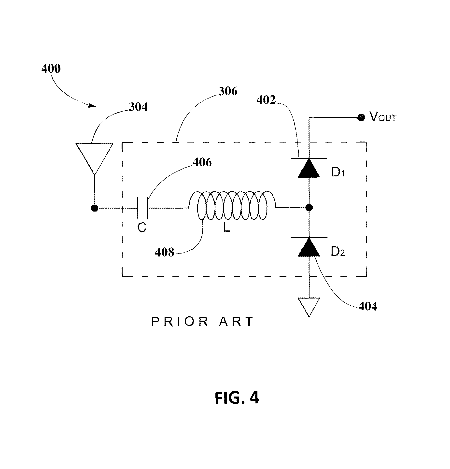
Half-bridge rectifiers are commonly used in power converters to provide half-wave rectification of alternating current. A typical half-bridge rectifier include two diodes which are inherently inefficient conductors producing a number of well-known problems. One problem resulting from the inefficiency of diodes is that they produce a forward voltage drop. This is most noticeable in low-voltage power converters where the voltage drop may be a significant proportion of the desired voltage output. Schottky diodes, which exhibit very low voltage drops, are often used to minimize the problem, but are an expensive solution. Conventional half-wave bridge rectifiers utilize junction diodes which show a forward bias voltage drop of approximately 0.7V. Thus, for a half-wave bridge rectifier, the resulting voltage drop relative to the input voltage can be as high as 1.4 volts. Another problem results from the heat dissipated by diodes, particularly in high frequency switching power supplies. Apart from reducing overall efficiency of the power converter, resulting high temperatures also reduce the reliability of components. Thus, additional design effort may be required to overcome the problems, and other factors such as the dimensions of the system may be affected as a result.
As such, there is a need for synchronous rectifiers characterized by low power loss characteristics and low associated heat loss for wireless power transfer systems that efficiently and safely transfer power at varying power levels to increase power transmission efficiency to electronic devices.
SUMMARY
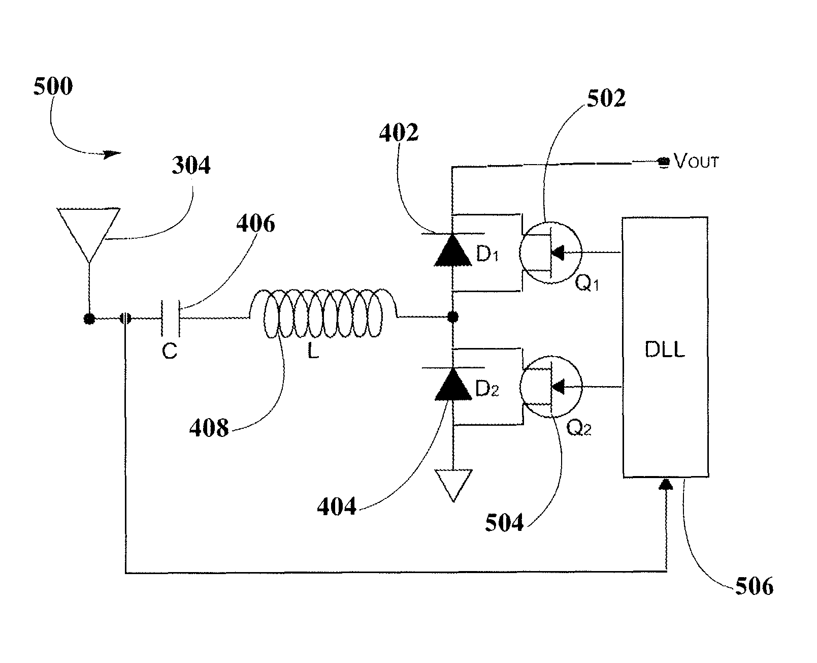
According to embodiments, it is an object of the present disclosure to provide synchronous rectifier (SR) circuit topologies designed for wireless power transmission receivers of a plurality of system configuration and power transfer control schemes. The design of SR circuit topologies of present disclosure may include a plurality of switching control schemes for power conversion where the voltage output from a wireless transmitter is received by a wireless receiver antenna array and may be transferred output voltage for other modules in the wireless receiver when the SR is conductive.
The plurality of SR circuit topologies may be designed to be low cost, complexity and size, in which diode conduction may be limited and capable of operating at high switching frequencies to reduce reverse recovery losses and voltage stresses, enabling low power loss characteristics of the disclosed SR circuit topologies.
Since the voltage drop across a controlled rectifier is smaller than the voltage drop across an uncontrolled rectifier, the output voltage may undergo a transient if the controlled rectifier is suddenly enabled. To avoid the transient, the controlled rectifiers may be turned on with a slowly changing average on-state voltage during a conduction time that may be a portion of the overall switching cycle. In order to accomplish these and other objects of the present disclosure, the plurality of switching control schemes may include methods of controlling the synchronous rectifier with switching FET transistors which may control conduction of the synchronous rectifier in accordance with the level of voltage and frequency that may be detected at the input terminals, providing phase-shifted signals for the FET transistors to allow conduction and transfer of the converted power with a significant reduction of forward voltage drop and power losses.
Accordingly, in an embodiment, a control-driven synchronous rectifier circuit topology may be enabled using a delay-locked loop (DLL) clock to control switching of FET transistors in the synchronous rectifier and to provide a practically lossless switching and reduced forward voltage drop improving efficiency of power transfer. In this embodiment, conduction control of synchronous rectification may be enabled for a plurality of high-frequency signals received from a wireless transmitter including a level of high-frequency signals which may be within the 900 MHz, 2.4 GHz, and 5.7 GHz unlicensed bands. The task of implementing control-driven SR may require accurate timing adjustment algorithms that can be designed discretely, but are much simpler when integrated into an integrated circuit solution, such as a delay-locked loop.
In an another aspect of present disclosure a synchronous rectifier circuit topology may be enabled using phase shifters to provide a significantly less loss switching and reduced forward voltage drop improving efficiency of power transfer. In this synchronous rectifier circuit topology, FET transistors may be driven by gate-drive signals derived from the phase shifters for conduction control of synchronous rectification of a plurality of high-frequency signals received from wireless transmitter. In present embodiment, the level of high-frequency signals may be within the 900 MHz, 2.4 GHz, and 5.7 GHz unlicensed bands.
In yet another aspect, present disclosure may include a synchronous rectifier circuit topology using a switching control scheme provided by wavelength links, which may be added as a frequency-division demultiplexing of the signal received by the antenna element of a wireless power receiver from a wireless transmitter. Wavelength links may be of different wavelength spacing in order to have the required phase shifting to enable switching control of FET transistors and to provide the proper timing for current to flow through diodes coupled to FET transistors. The focus on high conduction times per switching control scheme required provides a significantly less loss switching and reduced forward voltage drop improving efficiency of power transfer.
Numerous other aspects, features and benefits of the present disclosure may be made apparent from the following detailed description taken together with the drawing figures.
BRIEF DESCRIPTION OF THE DRAWINGS
The present disclosure can be better understood by referring to the following figures. The components in the figures are not necessarily to scale, emphasis instead being place upon illustrating the principles of the disclosure. In the figures, reference numerals designate corresponding parts throughout the different views.
FIG. 1 illustrates wireless power transmission using pocket forming, according to an embodiment.
FIG. 2 depicts a block diagram of a transmitter, which may be used for wireless power transmission systems, according to an embodiment.
FIG. 3 shows a block diagram of a receiver which can be used for wireless powering or charging one or more electronic devices, according to an embodiment.
FIG. 4 represents a circuit diagram of a half-bridge diode rectifier of the prior art, according to an embodiment.
FIG. 5 illustrates a circuit diagram of a synchronous rectifier including a half-bridge diode-FET transistor rectifier and a delayed-lock loop clock for conduction control, according to an embodiment.
FIG. 6 corresponds to a graph of waveforms depicting input voltage received, gate drive control signal and output voltage during conduction times of a synchronous rectifier, according to an embodiment.
FIG. 7 depicts a circuit diagram of a synchronous rectifier including a half-bridge diode-FET transistor rectifier and phase shifters for conduction control, according to an embodiment.
FIG. 8 shows a circuit diagram of a synchronous rectifier including a half-bridge diode-FET transistor rectifier and phase shifted wavelength lines for conduction control, according to an embodiment.
DETAILED DESCRIPTION
The present disclosure is here described in detail with reference to embodiments illustrated in the drawings, which form a part here. Other embodiments may be used and/or other changes may be made without departing from the spirit or scope of the present disclosure. The illustrative embodiments described in the detailed description are not meant to be limiting of the subject matter presented here.
As used here, the following terms may have the following definitions:
"Wireless device" refers to any electronic device able to communicate using one or more suitable wireless technologies. Suitable devices may include client devices in wireless networks and may be part of one or more suitable wireless technologies, including Wi-Fi and Bluetooth amongst others.
"Wireless transmitter" refers to a device, including a chip which may generate two or more RF signals, at least one RF signal being phase shifted and gain adjusted with respect to other RF signals substantially, all of which pass through one or more RF antenna such that focused RF signals are directed to a target.
"Wireless receiver" refers to a device including at least one antenna element, at least one rectifying circuit and at least one power converter, which may utilize pockets of energy for powering, or charging a wireless device.
"Pocket-forming" may refer to generating two or more RF waves which converge in 3-d space, forming controlled constructive and destructive interference patterns.
"Adaptive pocket-forming" may refer to dynamically adjusting pocket-forming to regulate power on one or more targeted receivers.
"Synchronous rectifier" refers to a power transmission circuit including active rectifiers controlled by switches such as transistors for improving the efficiency of rectification. The control circuitry for active rectification usually uses sensors for the voltage of the input AC to open the transistors at the correct times to allow current to flow in the correct direction.
"FET transistor" refers to a switch used to open or close an analog or digital circuit.
"Delay-locked loop clock" refers to a digital circuit used to change the phase of a clock signal with a periodic waveform to enhance timing characteristics of integrated circuits.
The present disclosure may provide synchronous rectifier (SR) circuit topologies designed for wireless power transmission receivers of a plurality of system configuration and power transfer control schemes. The design of SR circuit topologies of present disclosure may include a plurality of switching control schemes for power conversion where the voltage output from a wireless transmitter is received by a wireless receiver antenna array and may be transferred output voltage for other modules in the wireless receiver when the SR is conductive.
Wireless Power Transmission System Hardware Configuration
FIG. 1 illustrates a wireless power transmission 100 using pocket-forming. A transmitter 102 may transmit controlled Radio Frequency (RF) waves 104 which may converge in 3-d space. These RF waves 104 may be controlled through phase and/or relative amplitude adjustments to form constructive and destructive interference patterns (pocket-forming). Pockets of energy 106 may be formed at constructive interference patterns and can be 3-dimensional in shape, while null-spaces may be generated at destructive interference patterns. A receiver 108 may then utilize pockets of energy 106 produced by pocket-forming for charging or powering a cordless electronic device 110, for example, a smartphone, a tablet, a laptop computer (as shown in FIG. 1), a music player, an electronic toy, and the like. In some embodiments, there can be multiple transmitters 102 and/or multiple receivers 108 for powering various electronic devices 110 at the same time. In other embodiments, adaptive pocket-forming may be used to regulate the power transmitted to electronic devices 110.
FIG. 2 depicts the block diagram of transmitter 102 which may be used in wireless power transmission 100. Transmitter 102 may include a housing 202, at least two or more antenna elements 204, at least one RF integrated circuit (RFIC) 206, at least one digital signal processor (DSP) or micro-controller 208, and one communications component 210. Housing 202 can be made of any suitable material which may allow for signal or wave transmission and/or reception, for example plastic or hard rubber. Antenna elements 204 may include suitable antenna types for operating in frequency bands such as 900 MHz, 2.5 GHz or 5.8 GHz as these frequency bands conform to Federal Communications Commission (FCC) regulations part 18 (Industrial, Scientific and Medical equipment). Antenna elements 204 may include vertical or horizontal polarization, right hand or left hand polarization, elliptical polarization, or other suitable polarizations as well as suitable polarization combinations. Suitable antenna types may include, for example, patch antennas with heights from about 1/8 of an inch to about 8 inches and widths from about 1/8 of an inch to about 6 inches. Other antenna elements 204 types that may be used include meta-materials based antennas, dipole antennas, and planar inverted-F antennas (PIFAs), amongst others.
RFIC 206 may include a proprietary chip for adjusting phases and/or relative magnitudes of RF signals which may serve as inputs for antenna elements 204 for controlling pocket-forming. These RF signals may be produced using a power source 212 and a local oscillator chip (not shown) using a suitable piezoelectric material. Micro-controller 208 may then process information sent by receiver 108 through communications component 210 for determining optimum times and locations for pocket-forming. Communications component 210 may be based on standard wireless communication protocols which may include Bluetooth, Wi-Fi or ZigBee. In addition, communications component 210 may be used to transfer other information, such as an identifier for the device or user, battery level, location, or other such information. Other communications components 210 may be possible, including radar, infrared cameras or sound devices for sonic triangulation of electronic device 110 position.
FIG. 3 shows a block diagram of receiver 108 which can be used for wireless powering or charging one or more electronic devices 110 as exemplified in wireless power transmission 100. According to some aspects of this embodiment, receiver 108 may operate with the variable power source generated from transmitted RF waves 104 to deliver constant and stable power or energy to electronic device 110. In addition, receiver 108 may use the variable power source generated from RF waves 104 to power up electronic components within receiver 108 for proper operation.
Receiver 108 may be integrated in electronic device 110 and may include a housing (not shown in FIG. 3) that can be made of any suitable material to allow for signal or wave transmission and/or reception, for example plastic or hard rubber. This housing may be an external hardware that may be added to different electronic equipment, for example in the form of cases, or can be embedded within electronic equipment as well.
Receiver 108 may include an antenna array 302 which may convert RF waves 104 or pockets of energy 106 into electrical power. Antenna array 302 may include one or more antenna elements 304 operatively coupled with one or more rectifiers 306. RF waves 104 may exhibit a sinusoidal shape within a voltage amplitude and power range that may depend on characteristics of transmitter 102 and the environment of transmission. The environment of transmission may be affected by changes to or movement of objects within the physical boundaries, or movement of the boundaries themselves. It is also affected by changes to the medium of transmission; for example, changes to air temperature or humidity. As a result, the voltage or power generated by antenna array 302 may be variable. As an illustrative embodiment, and not by way of limitation, the alternating current (AC) voltage or power generated by antenna element 304 from transmitted RF waves 104 or pocket of energy 106 may vary from about 0 volts or 0 watt to about 5 volts at 3 watts.
Antenna element 304 may include suitable antenna types for operating in frequency bands similar to the bands described for transmitter 102 from FIG. 2. Antenna element 304 may include vertical or horizontal polarization, right hand or left hand polarization, elliptical polarization, or other suitable polarizations as well as suitable polarization combinations. Using multiple polarizations can be beneficial in devices where there may not be a preferred orientation during usage or whose orientation may vary continuously through time, for example electronic device 110. On the contrary, for devices with well-defined orientations, for example a two-handed video game controller, there might be a preferred polarization for antennas which may dictate a ratio for the number of antennas of a given polarization. Suitable antenna types may include patch antennas with heights from about 1/8 inches to about 6 inches and widths from about 1/8 inches to about 6 inches. Patch antennas may have the advantage that polarization may depend on connectivity, i.e. depending on which side the patch is fed, the polarization may change. This may further prove advantageous as receiver 108 may dynamically modify its antenna polarization to optimize wireless power transmission 100.
Rectifier 306 may include diodes or resistors, inductors or capacitors to rectify the AC voltage generated by antenna element 304 to direct current (DC) voltage. Rectifier 306 may be placed as close as is technically possible to antenna element 304 to minimize losses. In one embodiment, rectifier 306 may operate in synchronous mode, in which case rectifier 306 may include switching elements that may improve the efficiency of rectification. As an illustrative embodiment, and not by way of limitation, output of rectifier 306 may vary from about 0 volts to about 5 volts.
An input boost converter 308 can be included in receiver 108 to convert the variable DC output voltage of rectifier 306 into a more stable DC voltage that can be used by components of receiver 108 and/or electronic device 110. Input boost converter 308 may operate as a step-up DC-to-DC converter to increase the voltage from rectifier 306 to a voltage level suitable for proper operation of receiver 108. As an illustrative embodiment, and not by way of limitation, input boost converter 308 may operate with input voltages of at least 0.4 volts to about 5 volts to produce an output voltage of about 5 volts. In addition, input boost converter 308 may reduce or eliminate rail-to-rail deviations. In one embodiment, input boost converter 308 may exhibit a synchronous topology to increase power conversion efficiency.
As the voltage or power generated from RF waves 104 may be zero at some instants of wireless power transmission 100, receiver 108 can include a storage element 310 to store energy or electric charge from the output voltage produced by input boost converter 308. In this way, storage element 310, through an output boost converter 316, may deliver continuous voltage or power to a load 312, where this load 312 may represent the battery or internal circuitry of electronic device 110 requiring continuous powering or charging. For example, load 312 may be the battery of a mobile phone requiring constant delivery of 5 volts at 2.5 watts.
Storage element 310 may include a battery 314 to store power or electric charge from the voltage received from input boost converter 308. Battery 314 may be of different types, including but not limited to, alkaline, nickel-cadmium (NiCd), nickel-metal hydride (NiHM), and lithium-ion, among others. Battery 314 may exhibit shapes and dimensions suitable for fitting receiver 108, while charging capacity and cell design of battery 314 may depend on load 312 requirements. For example, for charging or powering a mobile phone, battery 314 may deliver a voltage from about 3 volts to about 4.2 volts.
In another embodiment, storage element 310 may include a capacitor (not shown in FIG. 3) instead of battery 314 for storing and delivering electrical charge as required by the receiver. As a way of example, in the case of charging or powering a mobile phone, receiver 108 may include a capacitor with operational parameters matching the load device's power requirements.
Receiver 108 may also include output boost converter 316 operatively coupled with storage element 310 and input boost converter 308, where this output boost converter 316 may be used for matching impedance and power requirements of load 312. As an illustrative embodiment, and not by way of limitation, output boost converter 316 may increase the output voltage of battery 314 from about 3 or 4.2 volts to about 5 volts which may be the voltage required by the battery or internal circuitry of electronic device 110. Similarly to input boost converter 308, output boost converter 316 may be based on a synchronous topology for enhancing power conversion efficiency.
Storage element 310 may provide power or voltage to a communication subsystem 318 which may include a low-dropout regulator (LDO 320), a main system micro-controller 322, and an electrically erasable programmable read-only memory (EEPROM 324). LDO 320 may function as a DC linear voltage regulator to provide a steady voltage suitable for low energy applications as in main system micro-controller 322. Main system micro-controller 322 may be operatively coupled with EEPROM 324 to store data for the operation and monitoring of receiver 108. Main system micro-controller 322 may also include a clock (CLK) input and general purpose inputs/outputs (GPIOs).
In one embodiment, main system micro-controller 322 in conjunction with EEPROM 324 may run an algorithm for controlling the operation of input boost converter 308 and output boost converter 316 according to load 312 requirements. Main system micro-controller 322 may actively monitor the overall operation of receiver 108 by taking one or more power measurements 326 (ADC) at different nodes or sections as shown in FIG. 3. For example, micro-controller 322 may measure how much voltage or power is being delivered at rectifier 306, input boost converter 308, battery 314, output boost converter 316, communication subsystem 318, and/or load 312. Main system micro-controller 322 may communicate these power measurements 326 to load 312 so that electronic device 110 may know how much power it can pull from receiver 108. In another embodiment, main system micro-controller 322, based on power measurements 326, may control the power or voltage delivered at load 312 by adjusting the load current limits at output boost converter 316. Yet in another embodiment, a maximum power point tracking (MPPT) algorithm may be executed by main system micro-controller 322 to control and optimize the amount of power that input boost converter 308 can pull from antenna array 302.
In another embodiment, main system micro-controller 322 may regulate how power or energy can be drained from storage element 310 based on the monitoring of power measurements 326. For example, if the power or voltage at input boost converter 308 runs too low, then micro-controller 322 may direct output boost converter 316 to drain battery 314 for powering load 312.
Receiver 108 may include a switch 328 for resuming or interrupting power being delivered at load 312. In one embodiment, micro-controller 322 may control the operation of switch 328 according to terms of services contracted by one or more users of wireless power transmission 100 or according to administrator policies.
Half-Bridge Diode Rectifier of the Prior Art
FIG. 4 represents a circuit diagram 400 of a half-bridge diode rectifier 401 of the prior art, according to embodiment shown in FIG. 3 as antenna array 302, including antenna element 304.
When an alternating RF signal is received from wireless transmitter 102, a direct voltage output V.sub.OUT may be drawn from the output terminals of the half-bridge diode rectifier 401.
Two diodes, D.sub.1 and D.sub.2, respectively identified as diode 402 and diode 404 are wired in series upstream and connected to output terminal. Antenna element 304 is connected in series to capacitor 406, which is connected in series to inductor 408, both acting as the resonant filter for the power signal being transferred from wireless transmitter 102 and received by antenna element 304 of wireless power receiver 108.
When the polarity of the alternating RF signal received may be positive, current flows through the first upstream diode D.sub.1 and when the polarity of the alternating RF signal received is negative, current flows through second upstream diode D.sub.2.
Half-bridge diode rectifiers, such as that shown in FIG. 4, may be used to produce an output with a fixed polarity that is independent of the polarity of the input. Half-bridge diode rectifiers may be used in AC-to-DC power converters, for example. Optionally, the output may be smoothed by a smoothing capacitor (not shown).
It may be noticed that as output voltages drop, the diode's forward voltage is more significant and may reduce conversion efficiency. Physical limitations prevent the forward voltage drop of diodes 402, 404 from being reduced to a level of voltage drop that may be less than about 0.3 V. Additionally, power is lost from each diode 402, 404 with each reversal of polarity. In high frequency power converters, where the polarity of the input signal may oscillate at frequencies of 100 kHz or more, such power losses may result in significant heating of the rectifier circuit and other components surrounding the rectifier. This situation may result in reduced reliability or failure of the rectifier circuit.
Control-Driven Synchronous Rectifier Circuit Topology
FIG. 5 illustrates a circuit diagram 500 of a synchronous rectifier 501 for wireless power receiver 108, connected to antenna element 304 and including a resonant filter that includes capacitor 406 and inductor 408, according to an embodiment. In this circuit, synchronous rectification may be enabled by a half-bridge rectifier configuration using diode 402 coupled to FET transistor 502 (Q1) and diode 404 coupled to FET transistor 504. This half-bridge rectifier configuration using synchronous rectification with coupled diode 402 and FET transistor 502, and coupled diode 404 and FET transistor 504 may be used to improve the efficiency limit which may result from using a half-bridge diode rectifier of prior art. As power conversion efficiency is primarily a function of the output voltage, output current, and the on-resistance and forward voltage drop of diodes 402, 404, adding FET transistors 502, 504 may provide significant improvement in power transfer from wireless transmitter 102 to wireless power receiver 108. Replacing a half-bridge diode rectifier of prior art with a synchronous rectifier 501 depicted in circuit diagram 500 may introduce a synchronous rectifier 501 possessing almost linear resistance characteristics and a lower forward-voltage drop. Consequently, the rectifier conduction loss may be reduced.
In this synchronous rectifier circuit topology, FET transistors 502, 504 may be driven by gate-drive signals derived from delayed-lock loop (DLL) clock 506 for conduction control of synchronous rectification of a plurality of high-frequency signals received from wireless transmitter 102. In present embodiment, the level of high-frequency signals may be within the 900 MHz, 2.4 GHz, and 5.7 GHz unlicensed bands.
Conduction times which may result by driving the half-bridge synchronous rectifiers from DLL clock 506 may reach a maximum conduction time of FET transistor 502 because it has no effect of the conduction time of current through diode 404 during dead time given that during dead time FET transistor 504 is in off state.
DLL clock 506 may be used to change the phase of the clock signal controlling FET transistors 502, 504 with a delay chain of delay gate signals which may be phase-locked depending on the frequency of the signal received by antenna element 304.
The precise gate-drive timing provided by DLL clock 506 may allow that when conduction through diode 402 may be applied or terminated, at the same instant conduction through diode 404 may be terminated or applied.
Circuit diagram 500 may be modified using a separate antenna element (not shown in FIG. 5) which is not included in antenna array 302. A modified synchronous rectifier circuit topology may be implemented by having DLL clock 506 directly connected to this second antenna element rather than deriving the control signal from the first antenna element 304 as shown in FIG. 5. The use of a separate antenna element connected to DLL clock 506 may prevent increasing the input impedance from antenna element 304 thus causing a reduction in the efficiency of the synchronous rectifier 501.
Switching Control Scheme
FIG. 6 corresponds to a graph of waveforms 600 depicting voltage received and conduction times of synchronous rectifier 501, for wireless power receiver 108 described in FIG. 3.
In FIG. 6, waveform 602 may represent the input voltage (V.sub.A) received by antenna element 304; waveform 604 may illustrate the voltage of gate signals (V.sub.GS) respectively applied to FET transistor 502, 504 to control conduction; and waveform 606 may show the output voltage (V.sub.OUT) at the terminals of synchronous rectifier 501.
The gate-drive timing of SRs may not allow conduction of diodes 402, 404 of synchronous rectifier 501 except for the unavoidable conduction of diode 404 during the dead time. This may only be possible with a very precise gate-drive timing where the gate-drive for FET transistor 502 may be applied or terminated at the same instant the gate-drive of FET transistor 504 may be terminated or applied. In practical applications, any accidental, brief overlapping of the gate-drive signals that turn on both. SRs simultaneously may cause a short-circuit which may lower efficiency or, in severe cases, may cause failure of the synchronous rectifier. To avoid simultaneous conduction of SRs in practical applications, a delay between the gate-drive signals may be introduced. Since during the delay period no gate-drive signal is applied to the SRs, the diodes 402, 404 of the SRs are conducting. This not only increases conduction loss but also introduces reverse-recovery loss. Therefore, the performance of control-driven SRs is strongly dependent on the timing of the gate drive that may be enabled using DLL clock 506 as seen in circuit diagram 500. This may be seen in waveform 604 for which a positive gate signal (+V.sub.GS) may be applied from DLL clock 506 to FET transistor 502 for a conduction time, t.sub.c, during which FET transistor 504 is an off state. During FET transistor 502 conduction time, losses due to voltage drop may be practically the voltage drop losses of FET transistor 502, which are much lower than the voltage drop losses of diode 402, thus allowing current to flow through only diode 402 during the high conduction time. Similarly, since input voltage V.sub.A is from a monotonic power source, DLL clock 506 has to phase shift the current to turn on FET transistor 504 at an appropriate time once there is no current through diode 402, then allowing current to flow through diode 404 with a minimum level of voltage drop losses, which are mainly related to the voltage drop losses of FET transistor 504, during the high conduction time during the negative voltage of gate signal (-V.sub.GS).
As seen in waveform 606, the switching control that may be provided by DLL clock 506 may result in a more significant level of power transfer to the other components in wireless power receiver 108. Waveform 606, when DLL clock 506 is operating, has a focus on high conduction time.
As seen, both SR gate drives may be regulated and, therefore, independent of input voltage variations or incoming power variations, so switching transitions remain constant over line and load. Since the output is controlled by the DLL clock 506, decisions may be made regarding when to turn off the SRs based on load current or output voltage. Optimizing proper SR gate drive timing in implementing control-driven SR often may require more accurate timing adjustment algorithms that can be designed discretely, but are much simpler when integrated into an integrated circuit solution, such as a DLL clock 506.
Synchronous Rectifier Circuit Topology Including Phase Shifters
FIG. 7 depicts a circuit diagram 700 of a phase-shifted synchronous rectifier 701 for wireless power receiver 108, connected to antenna element 304 and including resonant filter that includes capacitor 406 and inductor 408, according to an embodiment. In this circuit, synchronous rectification may be enabled by a half-bridge rectifier configuration using diode 402 coupled to FET transistor 502 (Q1) and diode 404 coupled to FET transistor 504. This half-bridge rectifier configuration using synchronous rectification with coupled diode 402 and FET transistor 502, and coupled diode 404 and FET transistor 504 may be used to improve the efficiency limit which may result from using a half-bridge diode rectifier of prior art. As power conversion efficiency is primarily a function of the output voltage, output current, and the on-resistance and forward voltage drop of diodes 402, 404, adding FET transistors 502, 504 may provide significant improvement in power transfer from wireless transmitter 102 to wireless power receiver 108. Replacing a half-bridge diode rectifier of prior art with a phase-shifted synchronous rectifier 701 depicted in circuit diagram 700 may introduce a synchronous rectifier possessing almost linear resistance characteristics and a lower forward-voltage drop. Consequently, the rectifier conduction loss may be reduced.
In this synchronous rectifier circuit topology, FET transistors 502, 504 may be driven by gate-drive signals derived from phase shifters 702, 704 for conduction control of synchronous rectification of a plurality of high-frequency signals received from wireless transmitter 102. In present embodiment, the level of high-frequency signals may be within the 900 MHz, 2.4 GHz, and 5.7 GHz unlicensed bands.
Phase shifters 702, 704 may be used to change the phase of the gate signal controlling FET transistors 502, 504 which may be phase-locked depending on the frequency of the signal received by antenna element 304.
The accurate gate-drive timing provided by phase shifters 702, 704 may allow that when conduction through diode 402 may be applied or terminated, at the same instant conduction through diode 404 may be terminated or applied.
Switching controlling for a phase-shifted synchronous rectifier 701 may start by developing two gate signal drives with a method of varying the phase relationship between them from 90.degree. to 180.degree.. Each gate signal drive from phase shifters 702, 704 may have an output which alternates with a 50% duty cycle to alternately drive FET transistor 502, 504. As the frequency of the incoming signal may change phase shifters 702, 704 may adapt to maintain the same level of current passing through diode 402 and diode 404, respectively, maintaining focus on high conduction times per switching control scheme previously described in FIG. 6, so that they run at constant frequency and the phase relationship between the two complimentary gate signal may enable that both FET transistors 502, 504 may turn on and off with zero voltage across them, resulting in close to lossless switching when proper timing may be provided.
Therefore, the performance of SRs driven by phase shifters 702, 704 is strongly dependent on the timing of the gate drive signals that may be enabled, as seen in circuit diagram 700. This may be seen in waveform 604 for which a positive gate signal (+V.sub.GS) may be applied from phase shifter 702 to FET transistor 502 for a conduction time, t.sub.C, during which FET transistor 504 is on off state. During FET transistor 502 conduction time, losses due to voltage drop may be practically the voltage drop losses of FET transistor 502, which are much lower than the voltage drop losses of diode 402, thus allowing only current to flow through diode 402 during the high conduction time. Similarly, since input voltage V.sub.A is from a monotonic power source, phase shifter 704 have to phase shift current to turn on FET transistor 504 at appropriate time once there is no current through diode 402, then allowing current to flow through diode 404 with a minimum level of voltage drop losses, which are mainly related to the voltage drop losses of FET transistor 504, during the high conduction time during the negative voltage of gate signal (-V.sub.GS).
Synchronous Rectifier Circuit Topology Including Wavelength Links
FIG. 8 depicts a circuit diagram 800 of a frequency-division demultiplexing synchronous rectifier 801 for wireless power receiver 108, connected to antenna element 304 and resonant filter including capacitor 406 and inductor 408. In this circuit, synchronous rectification may be enabled by a half-bridge rectifier configuration using diode 402 coupled to FET transistor 502 (Q1) and diode 404 coupled to FET transistor 504. This half-bridge rectifier configuration using synchronous rectification with coupled diode 402 and FET transistor 502, and coupled diode 404 and FET transistor 504 may be used to improve the efficiency limit which may result from using a half-bridge diode rectifier of prior art. As power conversion efficiency is primarily a function of the output voltage, output current, and the on-resistance and forward voltage drop of diodes 402, 404, adding FET transistors 502, 504 may provide significant improvement in power transfer from wireless transmitter 102 to wireless power receiver 108 Replacing a half-bridge diode rectifier of prior art with a frequency-division demultiplexing synchronous rectifier 801 depicted in circuit diagram 800 may introduce a synchronous rectifier possessing almost linear resistance characteristics and a lower forward-voltage drop. Consequently, the rectifier conduction loss may be reduced.
In this synchronous rectifier circuit topology, FET transistors 502, 504 may be driven by gate-drive signals derived from wavelength links 802, 804 for conduction control of synchronous rectification of a plurality of high-frequency signals received from wireless transmitter 102. In present embodiment, the level of high-frequency signals may be within the 900 MHz, 2.4 GHz, and 5.7 GHz unlicensed bands.
Wavelength links 802, 804 may be added as a frequency-division demultiplexing of the signal received by antenna element 304 from wireless transmitter 102. Wavelength links 802, 804 may be of different wavelength spacing in order to have the required phase shifting to enable switching control of FET transistor 502, 504 and providing the proper timing for current to flow through diodes 402, 404 focusing on high conduction times per switching control scheme previously described in FIG. 6, so that they run at constant frequency and the phase relationship between the two gate signals may enable that both FET transistors 502, 504 may turn on and off with zero voltage across them, resulting in close to lossless switching. Wavelength links 802, 804 may use spacing X and Y as shown in FIG. 8 within a range of about 1/4 .lamda., to 1/2 .lamda., at about 5.7 GHz.
Therefore, the performance of SRs driven by wavelength links 802, 804 is strongly dependent on the timing of the gate drive signals that may be enabled, as seen in circuit diagram 800. This may be seen in waveform 604 for which a positive gate signal (+V.sub.GS) may be applied from wavelength link 802 to FET transistor 502 for a conduction time, t.sub.C, during which FET transistor 504 is on off state. During FET transistor 502 conduction time, losses due to voltage drop may be practically the voltage drop losses of FET transistor 502, which are much lower than the voltage drop losses of diode 402, thus allowing only current to flow through diode 402 during the high conduction time. Similarly, since input voltage V.sub.A is from a monotonic power source, wavelength link 804 have to phase shift current to turn on FET transistor 504 at appropriate time once there is no current through diode 402, then allowing current to flow through diode 404 with a minimum level of voltage drop losses, which are mainly related to the voltage drop losses of FET transistor 504, during the high conduction time during the negative voltage of gate signal (-V.sub.GS).
While various aspects and embodiments have been disclosed, other aspects and embodiments may be contemplated. The various aspects and embodiments disclosed here are for purposes of illustration and are not intended to be limiting, with the true scope and spirit being indicated by the following claims.
* * * * *
D00000
D00001
D00002
D00003
D00004
D00005
D00006
D00007
D00008
XML
uspto.report is an independent third-party trademark research tool that is not affiliated, endorsed, or sponsored by the United States Patent and Trademark Office (USPTO) or any other governmental organization. The information provided by uspto.report is based on publicly available data at the time of writing and is intended for informational purposes only.
While we strive to provide accurate and up-to-date information, we do not guarantee the accuracy, completeness, reliability, or suitability of the information displayed on this site. The use of this site is at your own risk. Any reliance you place on such information is therefore strictly at your own risk.
All official trademark data, including owner information, should be verified by visiting the official USPTO website at www.uspto.gov. This site is not intended to replace professional legal advice and should not be used as a substitute for consulting with a legal professional who is knowledgeable about trademark law.