Camera lens assembly
Wenren , et al.
U.S. patent number 10,295,793 [Application Number 15/511,228] was granted by the patent office on 2019-05-21 for camera lens assembly. This patent grant is currently assigned to Zhejiang Sunny Optics Co., LTD. The grantee listed for this patent is ZHEJIANG SUNNY OPTICS CO., LTD.. Invention is credited to Fujian Dai, Jianke Wenren.


View All Diagrams
| United States Patent | 10,295,793 |
| Wenren , et al. | May 21, 2019 |
Camera lens assembly
Abstract
A camera lens assembly is provided, including a first lens, a second lens, a third lens, a fourth lens, a fifth lens and a sixth lens from an object side of the camera lens assembly to an image side of the camera lens assembly in turn. The first lens has a positive refractive power; the second lens has a negative refractive power, an object-side surface of the second lens is convex and an image-side surface of the second lens is concave; the third lens has a positive refractive power; the fourth lens has a refractive power, an object-side surface of the fourth lens is concave and an image-side surface of the fourth lens is convex; the fifth lens has a refractive power, an object-side surface of the fifth lens is convex and an image-side surface of the fifth lens is convex; the sixth lens has a negative refractive power.
| Inventors: | Wenren; Jianke (Zhejiang, CN), Dai; Fujian (Zhejiang, CN) | ||||||||||
|---|---|---|---|---|---|---|---|---|---|---|---|
| Applicant: |
|
||||||||||
| Assignee: | Zhejiang Sunny Optics Co., LTD
(Ningbo, Zhejiang, CN) |
||||||||||
| Family ID: | 59224331 | ||||||||||
| Appl. No.: | 15/511,228 | ||||||||||
| Filed: | May 5, 2016 | ||||||||||
| PCT Filed: | May 05, 2016 | ||||||||||
| PCT No.: | PCT/CN2016/081187 | ||||||||||
| 371(c)(1),(2),(4) Date: | March 14, 2017 | ||||||||||
| PCT Pub. No.: | WO2017/113557 | ||||||||||
| PCT Pub. Date: | July 06, 2017 |
Prior Publication Data
| Document Identifier | Publication Date | |
|---|---|---|
| US 20180143406 A1 | May 24, 2018 | |
Foreign Application Priority Data
| Dec 31, 2015 [CN] | 2015 1 1029991 | |||
| Dec 31, 2015 [CN] | 2015 2 1139834 U | |||
| Current U.S. Class: | 1/1 |
| Current CPC Class: | G02B 13/0045 (20130101); G02B 9/62 (20130101) |
| Current International Class: | G02B 9/62 (20060101); G02B 13/00 (20060101) |
| Field of Search: | ;359/713,756,759,757,738,761,762,350,557,740,763,793 ;348/355,373,294,374,311,340,360 |
References Cited [Referenced By]
U.S. Patent Documents
| 2012/0188654 | July 2012 | Huang |
| 2013/0215520 | August 2013 | Lai |
| 2015/0212296 | July 2015 | Huang et al. |
| 102621667 | Aug 2012 | CN | |||
| 202975455 | Jun 2013 | CN | |||
| 103543520 | Jan 2014 | CN | |||
| 203606558 | May 2014 | CN | |||
| 103869452 | Jun 2014 | CN | |||
| 204790153 | Nov 2015 | CN | |||
| 105445915 | Mar 2016 | CN | |||
| 205353448 | Jun 2016 | CN | |||
| 205374856 | Jul 2016 | CN | |||
| H01287616 | Nov 1989 | JP | |||
| 2013156579 | Aug 2013 | JP | |||
| 2014044372 | Mar 2014 | JP | |||
| 2014232147 | Dec 2014 | JP | |||
| 20140052907 | May 2014 | KR | |||
| 201331623 | Aug 2013 | TW | |||
Other References
|
International search report and written opinions for PCT application CN2016081187. cited by applicant . Office action from SIPO for CN application 201511032843.0. cited by applicant . Office action from SIPO for CN application 201511029991.7. cited by applicant . English translation of office action from SIPO for CN application 201511032843.0. cited by applicant . English translation of international search report for PCT application CN2016081187. cited by applicant . English translation of office action from SIPO for CN application 201511029991.7. cited by applicant. |
Primary Examiner: Dzierzynski; Evan P
Assistant Examiner: Broome; Sharrief I
Attorney, Agent or Firm: Martin & Ferraro, LLP
Claims
What is claimed is:
1. A camera lens assembly, comprising a first lens, a second lens, a third lens, a fourth lens, a fifth lens and a sixth lens from an object side of the camera lens assembly to an image side of the camera lens assembly in turn, wherein the first lens has a positive refractive power; the second lens has a negative refractive power, an object-side surface of the second lens is convex and an image-side surface of the second lens is concave; the third lens has a positive refractive power; the fourth lens has a refractive power, an object-side surface of the fourth lens is concave and an image-side surface of the fourth lens is convex; the fifth lens has a refractive power, an object-side surface of the fifth lens is convex and an image-side surface of the fifth lens is convex; the sixth lens has a negative refractive power; a total number of the lenses having the refractive power in the camera lens assembly is six; the camera lens assembly meets following formulas: |f/f3|+|f/f6|<1.0; and TTL/ImgH<1.46, wherein f3 represents an effective focal length of the third lens, f6 represents an effective focal length of the sixth lens, f represents an effective focal length of the camera lens assembly, TTL represents an axial distance from an object-side surface of the first lens to an imaging plane, and ImgH equals to half of a diagonal of an effective pixel region in the imaging plane.
2. The camera lens assembly according to claim 1, wherein the camera lens assembly meets a following formula: 1.0<CT3/CT4<1.6, wherein CT3 represents a central thickness of the third lens in an optical axis, and CT4 represents a central thickness of the fourth lens in the optical axis.
3. The camera lens assembly according to claim 1, wherein the camera lens assembly meets a following formula: -2.1<f6/f<-1.5.
4. The camera lens assembly according to claim 1, wherein the camera lens assembly meets a following formula: f/EPD<2.1, wherein EPD represents a diameter of an entrance pupil.
5. The camera lens assembly according to claim 1, wherein an image-side surface of the sixth lens is concave, and the camera lens assembly meets a following formula: -0.5<R12/R10<0, wherein R12 represents a curvature radius of the image-side surface of the sixth lens, and R10 represents a curvature radius of the image-side surface of the fifth lens.
6. The camera lens assembly according to claim 1, wherein the camera lens assembly meets a following formula: 0.8ImgH/f<1.0.
7. The camera lens assembly according to claim 1, wherein the camera lens assembly meets a following formula: 0.5<CT5/CT6<1.4, wherein CT5 represents a central thickness of the fifth lens in an optical axis, and CT6 represents a central thickness of the sixth lens in the optical axis.
8. The camera lens assembly according to claim 1, wherein the camera lens assembly meets a following formula: -1<f12/f6<-0.5, wherein f12 represents a combined focal length of the first lens and the second lens.
9. The camera lens assembly according to claim 1, wherein the camera lens assembly meets a following formula: 0.8<DT11/DT32<1.2, wherein DT11 represents an effective radius of an object-side surface of the first lens, and DT32 represents an effective radius of an image-side surface of the third lens.
10. The camera lens assembly according to claim 1, wherein the camera lens assembly meets a following formula: 0.35<DT11/DT62<0.5, wherein DT11 represents an effective radius of an object-side surface of the first lens, and DT62 represents an effective radius of an image-side surface of the sixth lens.
Description
CROSS REFERENCE TO RELATED APPLICATIONS
The present application is a U.S. National Phase application under 35 USC .sctn. 371 of the International Patent Application No. PCT/CN2016/081187, filed on May 5, 2016, which claims the benefit of prior Chinese Application Nos. 201511029991.7 and 201521139834.7, filed with the State Intellectual Property Office of P. R. China on Dec. 31, 2015. The entire contents of the before-mentioned patent applications are incorporated by reference as part of the disclosure of this U.S. application.
FIELD
The present disclosure relates to a field of photographing technology, in particular to a camera lens assembly.
BACKGROUND
Recently, with a development in chip technology such as CCD or CMOS, a camera lens assembly develops toward a high-pixel and miniaturization field. In order to meet such trend, a miniaturization and a high imaging performance are further required for the camera lens assembly applied to a portable electronic device.
The mainstream camera lens assembly at present generally includes five lenses, which faces difficulty in meeting a demand for analysis of higher pixel and higher quality, so it is necessary to increase the amount of lenses. However, an increase of the amount of lenses has a disadvantage on the miniaturization and lightweight of the camera lens assembly.
SUMMARY
The present disclosure seeks to solve at least one of the technical problems existing in the related art. Accordingly, embodiments of the present disclosure provide a camera lens assembly.
The camera lens assembly according to embodiments of the present disclosure includes a first lens, a second lens, a third lens, a fourth lens, a fifth lens and a sixth lens from an object side of the camera lens assembly to an image side of the camera lens assembly in turn. The first lens has a positive refractive power. The second lens has a negative refractive power, an object-side surface of the second lens is convex and an image-side surface of the second lens is concave. The third lens has a positive refractive power. The fourth lens has a refractive power, an object-side surface of the fourth lens is concave and an image-side surface of the fourth lens is convex. The fifth lens has a refractive power, an object-side surface of the fifth lens is convex and an image-side surface of the fifth lens is convex. The sixth lens has a negative refractive power. A total number of the lenses having the refractive power in the camera lens assembly is six. The camera lens assembly meets following formulas: |f/f3|+|f/f6|<1.0;TTL/ImgH<1.46,
in which f3 represents an effective focal length of the third lens, f6 represents an effective focal length of the sixth lens, f represents an effective focal length of the camera lens assembly, TTL represents an axial distance from an object-side surface of the first lens to an imaging plane, and ImgH equals to half of a diagonal of an effective pixel region in the imaging plane.
The camera lens assembly meeting above configurations has advantages of improving a spherical aberration and a comatic aberration, as well as increasing an imaging quality. Meanwhile, the configuration of the camera lens assembly is compact, which can reduce a volume of the camera lens assembly and shorten a total length of the camera lens assembly effectively, and thus the miniaturization of the camera lens assembly is kept.
In one embodiment, the camera lens assembly meets a following formula: 1.0<CT3/CT4<1.6,
in which CT3 represents a central thickness of the third lens in an optical axis, and CT4 represents a central thickness of the fourth lens in the optical axis.
In one embodiment, the camera lens assembly meets a following formula: -2.1<f6/f<-1.5.
In one embodiment, the camera lens assembly meets a following formula: f/EPD<2.1,
in which EPD represents a diameter of an entrance pupil.
In one embodiment, an image-side surface of the sixth lens is concave, and the camera lens assembly meets a following formula: -0.5<R12/R10<0,
in which R12 represents a curvature radius of the image-side surface of the sixth lens, and R10 represents a curvature radius of the image-side surface of the fifth lens.
In one embodiment, the camera lens assembly meets a following formula: 0.8ImgH/f<1.0,
In one embodiment, the camera lens assembly meets a following formula: 0.5<CT5/CT6<1.4,
in which CT5 represents a central thickness of the fifth lens in an optical axis, and CT6 represents a central thickness of the sixth lens in the optical axis.
In one embodiment, the camera lens assembly meets a following formula: -1<f12/f6<-0.5,
in which f12 represents a combined focal length of the first lens and the second lens.
In one embodiment, the camera lens assembly meets a following formula: 0.8<DT11/DT32<1.2,
in which DT11 represents an effective radius of an object-side surface of the first lens, and DT32 represents an effective radius of an image-side surface of the third lens.
In one embodiment, the camera lens assembly meets a following formula: 0.35<DT11/DT62<0.5,
in which DT11 represents an effective radius of an object-side surface of the first lens, and DT62 represents an effective radius of an image-side surface of the sixth lens.
Additional aspects and advantages of the present disclosure will be given in part in the following descriptions, become apparent in part from the following descriptions, or be learned from the practice of the present disclosure.
BRIEF DESCRIPTION OF THE DRAWINGS
These and other aspects and advantages of embodiments of the present disclosure will become apparent and more readily appreciated from the following descriptions made with reference to the drawings, in which:
FIG. 1 is a schematic view showing a camera lens assembly according to Embodiment 1 of the present disclosure;
FIG. 2 is a diagram showing a longitudinal aberration curve (mm) of the camera lens assembly in Embodiment 1;
FIG. 3 is a diagram showing an astigmatism curve (mm) of the camera lens assembly in Embodiment 1;
FIG. 4 is a diagram showing a distortion curve (%) of the camera lens assembly in Embodiment 1;
FIG. 5 is a diagram showing a lateral color curve (.mu.m) of the camera lens assembly in Embodiment 1;
FIG. 6 is a schematic view showing a camera lens assembly according to Embodiment 2 of the present disclosure;
FIG. 7 is a diagram showing a longitudinal aberration curve of the camera lens assembly in Embodiment 2;
FIG. 8 is a diagram showing an astigmatism curve (mm) of the camera lens assembly in Embodiment 2;
FIG. 9 is a diagram showing a distortion curve (%) of the camera lens assembly in Embodiment 2;
FIG. 10 is a diagram showing a lateral color curve (.mu.m) of the camera lens assembly in Embodiment 2;
FIG. 11 is a schematic view showing a camera lens assembly according to Embodiment 3 of the present disclosure;
FIG. 12 is a diagram showing a longitudinal aberration curve (mm) of the camera lens assembly in Embodiment 3;
FIG. 13 is a diagram showing an astigmatism curve (mm) the camera lens assembly in Embodiment 3;
FIG. 14 is a diagram showing a distortion curve (%) of the camera lens assembly in Embodiment 3;
FIG. 15 is a diagram showing a lateral color curve (.mu.m) of the camera lens assembly in Embodiment 3;
FIG. 16 is a schematic view showing a camera lens assembly according to Embodiment 4 of the present disclosure;
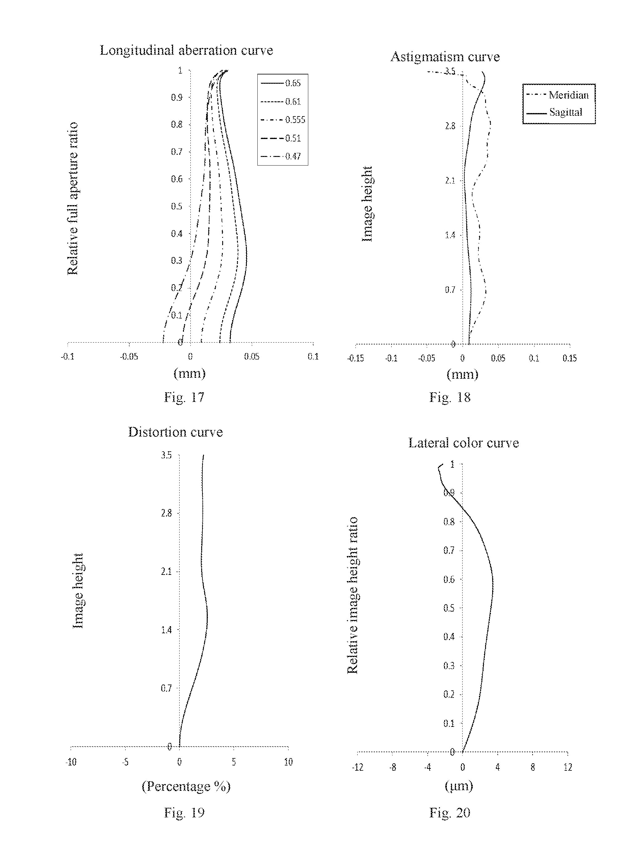
FIG. 17 is a diagram showing a longitudinal aberration curve (mm) of the camera lens assembly in Embodiment 4;
FIG. 18 is a diagram showing an astigmatism curve (mm) of the camera lens assembly in Embodiment 4;
FIG. 19 is a diagram showing a distortion curve (%) of the camera lens assembly in Embodiment 4;
FIG. 20 is a diagram showing a lateral color curve (.mu.m) of the camera lens assembly in Embodiment 4;
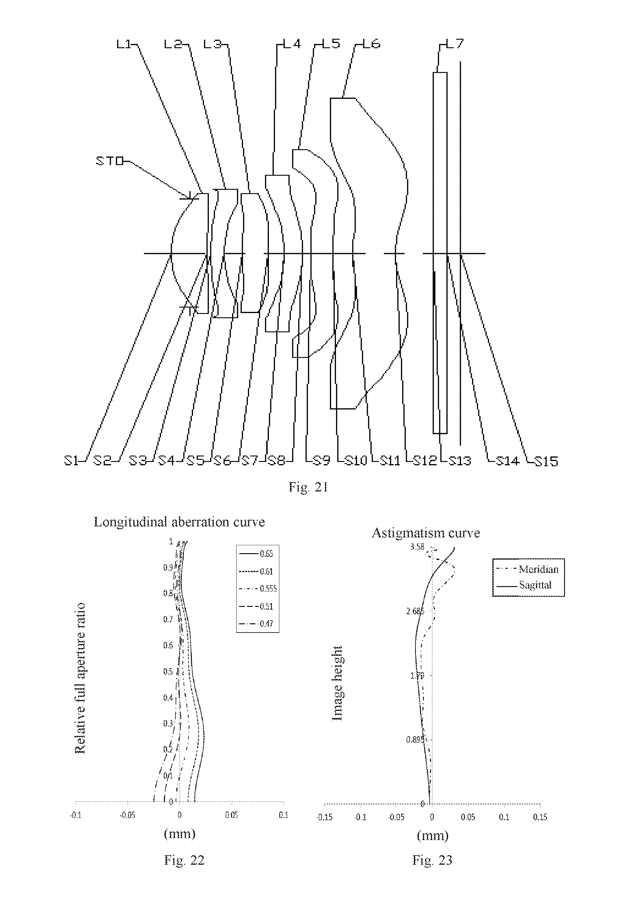
FIG. 21 is a schematic view showing a camera lens assembly according to Embodiment 5 of the present disclosure;
FIG. 22 is a diagram showing a longitudinal aberration curve (mm) of the camera lens assembly in Embodiment 5;
FIG. 23 is a diagram showing an astigmatism curve (mm) of the camera lens assembly in Embodiment 5;
FIG. 24 is a diagram showing a distortion curve (%) of the camera lens assembly in Embodiment 5:
FIG. 25 is a diagram showing a lateralcolor curve (.mu.m) of the camera lens assembly in Embodiment 5;
FIG. 26 is a schematic view showing a camera lens assembly according to Embodiment 6 of the present disclosure;
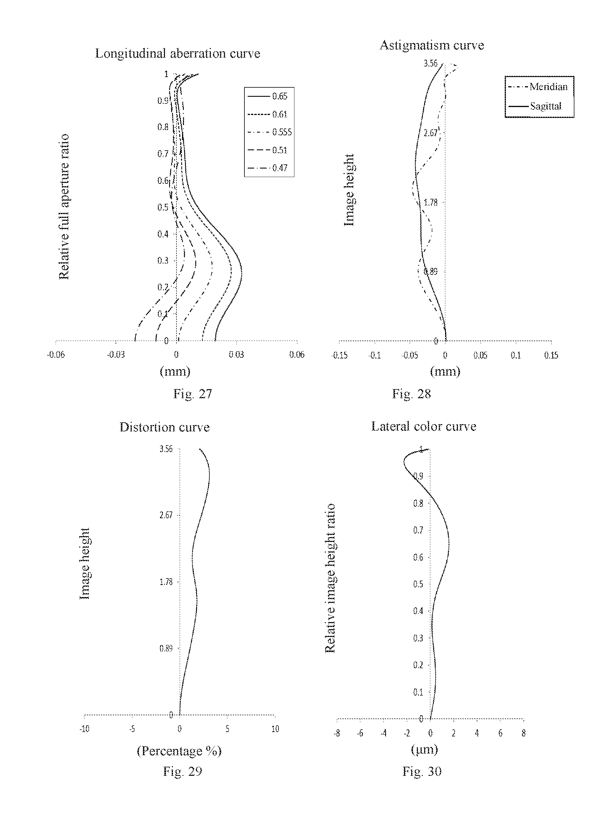
FIG. 27 is a diagram showing a longitudinal aberration curve (mm) of the camera lens assembly in Embodiment 6;
FIG. 28 is a diagram showing an astigmatism curve (mm) of the camera lens assembly in Embodiment 6;
FIG. 29 is a diagram showing a distortion curve (%) of the camera lens assembly in Embodiment 6;
FIG. 30 is a diagram showing a lateral color curve (.mu.m) of the camera lens assembly in Embodiment 6;
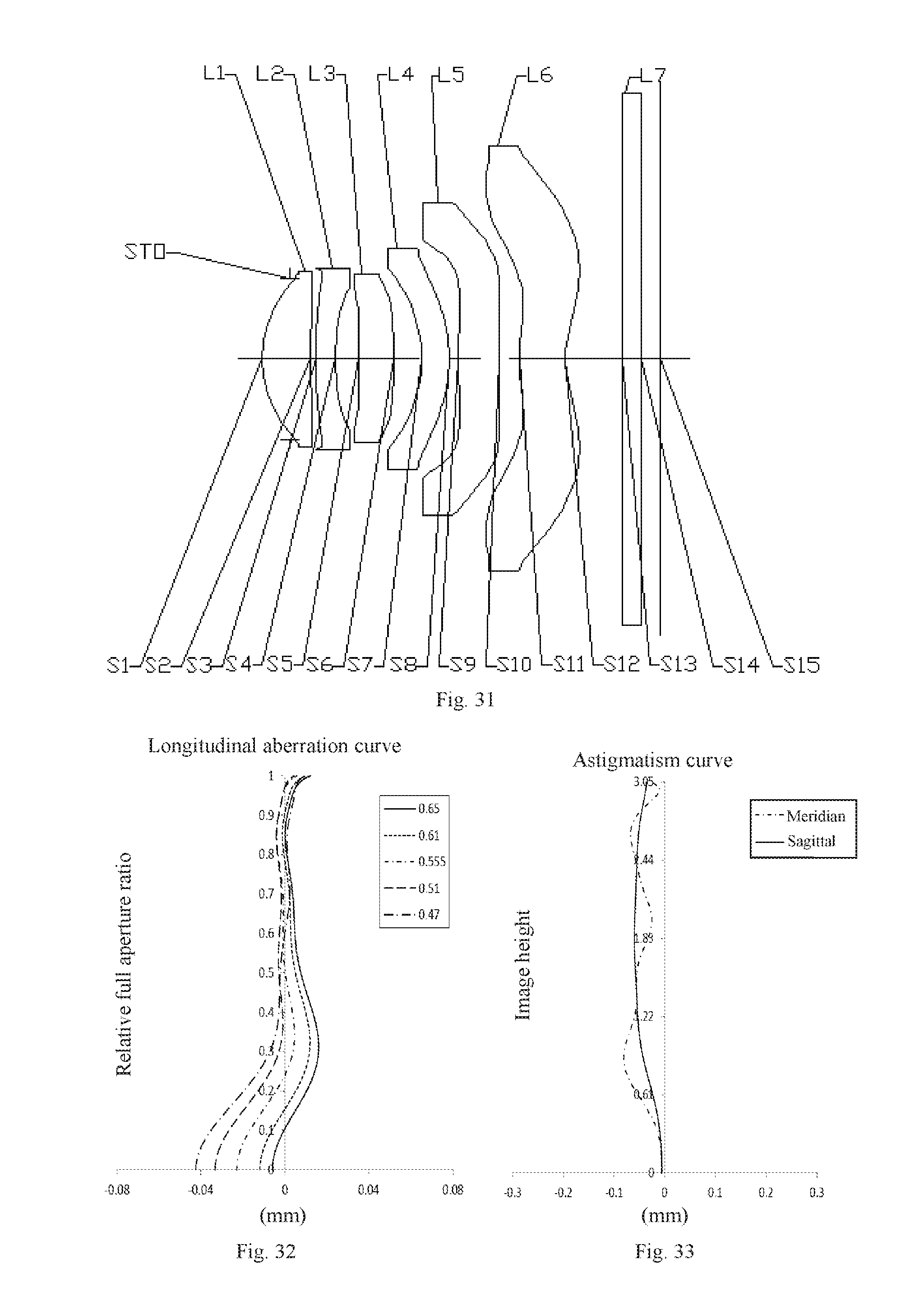
FIG. 31 is a schematic view showing a camera lens assembly according to Embodiment 7 of the present disclosure;
FIG. 32 is a diagram showing a longitudinal aberration curve (mm) of the camera lens assembly in Embodiment 7;
FIG. 33 is a diagram showing an astigmatism curve (mm) of the camera lens assembly in Embodiment 7;
FIG. 34 is a diagram showing a distortion curve (%) of the camera lens assembly in Embodiment 7;
FIG. 35 is a diagram showing a lateral color curve (.mu.m) of the camera lens assembly in Embodiment 7.
DETAILED DESCRIPTION
Embodiments of the present disclosure will be described in detail in the following descriptions, examples of which are shown in the accompanying drawings, in which the same or similar reference numerals represent the same or similar elements or elements having the same or similar functions throughout the descriptions. The embodiments described hereinafter with reference to the accompanying drawings are explanatory and illustrative, which are used to generally understand the present disclosure, but shall not be construed to limit the present disclosure.
In the specification, it is to be understood that terms such as "first" and "second" are used herein for purposes of description and are not intended to indicate or imply relative importance or significance or to imply the number of indicated technical features. Thus, the feature defined with "first" and "second" may comprise one or more of this feature. In the description of the present disclosure, unless specified otherwise, "a plurality of" means two or more than two.
In the description of the present disclosure, it should be noted that, unless otherwise clearly defined and limited, the terms "mounted", "connected", "connection" should be broadly understood, and may be, for example, fixed connections, detachable connections, or integral connections; may also be electrical connections or may communicate with each other; may also be direct connections or indirect connections via intermediation; may also be inner communications or interaction relationship of two elements, which can be understood by those ordinary skilled in the art according to specific situations.
Various embodiments and examples are provided in the following descriptions to implement different structures of the present disclosure. In order to simplify the present disclosure, certain elements and settings will be described. However, these elements and settings are only by way of example and are not intended to limit the present disclosure. In addition, reference numerals and/or reference letters may be repeated in different examples in the present disclosure, this repeating is for the purpose of simplification and clarity and does not refer to relations between different embodiments and/or settings. Furthermore, examples of specific processes and materials are provided in the present disclosure, however, it would be appreciated by those ordinary skilled in the art that other processes and/or materials may be also applied.
Referring to FIG. 1, a camera lens assembly according to a preferred embodiment of the present disclosure is provided, including a first lens L1, a second lens L2, a third lens L3, a fourth lens L4, a fifth lens L5 and a sixth lens L6 from an object side of the camera lens assembly to an image side of the camera lens assembly in turn.
The first lens L1 has a positive refractive power. The second lens L2 has a negative refractive power, an object-side surface S3 of the second lens L2 is convex and an image-side surface S4 of the second lens L2 is concave. The third lens L3 has a positive refractive power. The fourth lens L4 has a refractive power, an object-side surface S7 of the fourth lens L4 is concave and an image-side surface S8 of the fourth lens L4 is convex. The fifth lens L5 has a refractive power, an object-side surface S9 of the fifth lens L5 is convex and an image-side surface S10 of the fifth lens L5 is convex. The sixth lens L6 has a negative refractive power. A total number of the lenses having the refractive power in the camera lens assembly is six.
The camera lens assembly meets following formulas: |f/f3|+|f/f6|<1.0;TTL/ImgH<1.46,
in which f13 represents an effective focal length of the third lens L3, f6 represents an effective focal length of the sixth lens L6, f represents an effective focal length of the camera lens assembly, TTL represents an axial distance from an object-side surface S1 of the first lens L1 to an imaging plane S15, and ImgH equals to half of a diagonal of an effective pixel region in the imaging plane S15.
The camera lens assembly meeting above configurations has advantages of improving a spherical aberration and a comatic aberration, as well as increasing an imaging quality. Meanwhile, the configuration of the camera lens assembly is compact, which can reduce a volume of the camera lens assembly and shorten a total length of the camera lens assembly effectively, and thus the miniaturization of the camera lens assembly is kept.
Preferably, the camera lens assembly meets a following formula: 1.0<CT3/CT4<1.6,
in which CT3 represents a central thickness of the third lens L3 in an optical axis, and CT4 represents a central thickness of the fourth lens L4 in the optical axis.
The camera lens assembly meeting the above configuration contributes to reasonably setting the central thicknesses of the third lens and the fourth lens, such that it is easy to assemble the camera lens assembly and a sensitivity of the camera lens assembly is decreased.
Preferably, the camera lens assembly meets a following formula: -2.1<f6/f<-1.5.
The camera lens assembly meeting the above configuration allows a beam angle of the camera lens assembly to be gentle and decreases a tolerance sensitivity effectively.
Preferably, the camera lens assembly meets a following formula: f/EPD<2.1,
in which EPD represents a diameter of an entrance pupil.
The camera lens assembly meeting the above configuration contributes to obtaining a better imaging quality when photographing with the camera lens assembly in a dim illumination, as well as to blurring out a background so as to highlight a theme.
Preferably, an image-side surface S12 of the sixth lens L6 is concave, and the camera lens assembly meets a following formula: -0.5<R12/R10<0,
in which R12 represents a curvature radius of the image-side surface S12 of the sixth lens L6, and R10 represents a curvature radius of the image-side surface S10 of the fifth lens L5.
The camera lens assembly meeting the above configuration contributes to adjusting an incident angle of each field of view coming into a photosensitive element and avoiding a total reflection effectively.
Preferably, the camera lens assembly meets a following formula: 0.8ImgH/f<1.0,
in which ImgH equals to half of a diagonal of an effective pixel region in the imaging plane S15.
The camera lens assembly meeting the above configuration contributes to improving a filed angle of the camera lens assembly, so as to ensure the miniaturization of the camera lens assembly while providing a large filed angle.
Preferably, the camera lens assembly meets a following formula: 0.5<CT5/CT6<1.4,
in which CT5 represents a central thickness of the fifth lens L5 in the optical axis, and CT6 represents a central thickness of the sixth lens L6 in the optical axis.
The camera lens assembly meeting the above configuration contributes to reasonably setting the central thicknesses of the fifth lens L5 and the sixth lens L6, thus further ensuring the miniaturization of the camera lens assembly.
Preferably, the camera lens assembly meets a following formula: -1<f12/f6<-0.5,
in which f12 represents a combined focal length of the first lens L1 and the second lens L2.
The camera lens assembly meeting the above configuration contributes to reasonably allocating a focal power of system, effectively correcting the spherical aberration of system, and increasing the imaging quality further.
Preferably, the camera lens assembly meets a following formula: 0.8<DT11/DT32<1.2,
in which DT11 represents an effective radius of the object-side surface S1 of the first lens L1, and DT32 represents an effective radius of an image-side surface S6 of the third lens L3.
The camera lens assembly meeting the above configuration contributes to setting a size of a front end of the camera lens assembly, so as to effectively control the size of the front end of the camera lens assembly.
Preferably, the camera lens assembly meets a following formula: 0.35<DT11/DT62<0.5,
in which DT11 represents the effective radius of the object-side surface S1 of the first lens L1, and DT62 represents an effective radius of the image-side surface S12 of the sixth lens L6.
The camera lens assembly meeting the above configuration contributes to setting a field angle of a rear end of the camera lens assembly, such that more of lights entering through the camera lens assembly may be imaged in the imaging plane S15.
During imaging, the light sequentially passes through the six lenses and a light filter L7 having an object-side surface S13 and an image-side surface S14, and then is imaged in the imaging plane S15.
In some embodiments, the first lens L1, the second lens L2, the third lens L3, the fourth lens L4, the fifth lens L5 and the sixth lens L6 may all be aspheric lenses.
A surface shape of an aspheric surface is defined by a formula as below:
.times..times. ##EQU00001##
in which h represents a height from any point on the aspheric surface to the optical axis, c represents a vertex curvature, k represents a conic coefficient, Ai represents an i-th order aspheric correction coefficient.
Embodiment 1
With reference to FIG. 1 to FIG. 5, in embodiment 1, the camera lens assembly meets conditions in following tables 1, 2 and 3.
TABLE-US-00001 TABLE 1 Refractive Surface Surface Curvature Thick- index/abbe Conic No. type radius ness number coefficient OBJ spherical infinity infinity -- -- STO spherical infinity -0.2920 -- -- S1 aspheric 1.3021 0.5115 1.544/56.11 -0.8486 S2 aspheric 4.4009 0.0614 -- 0.3178 S3 aspheric 3.2359 0.2106 1.651/21.52 -0.3361 S4 aspheric 2.0787 0.2473 -- 0.2989 S5 aspheric 14.5996 0.3964 1.535/55.80 -0.9990 S6 aspheric -7.8561 0.2996 -- -1.0001 S7 spherical -1.5506 0.3000 1.651/21.52 -- S8 aspheric -1.6130 0.1000 -- -1.6410 S9 aspheric 7193.0239 0.4356 1.535/55.80 14.5392 S10 aspheric -18748.3936 0.2159 -- 0.2986 S11 aspheric 2.2799 0.4840 1.535/55.80 -0.8548 S12 aspheric 1.2688 0.6112 -- -1.0017 S13 spherical infinity 0.2100 1.517/64.17 -- S14 spherical infinity 0.1965 -- -- S15 spherical infinity -- -- --
TABLE-US-00002 TABLE 2 High order aspheric coefficients A4, A6, A8, A10, A12, A14, A16 of the aspheric lens are shown in the following table. Surface No. A4 A6 A8 A10 A12 A14 A16 S1 3.4250E-02 1.4834E-01 -5.6016E-01 1.5486E+00 -2.5668E+00 2.3559E+00 -9.5992E-01 S2 -3.3186E-01 6.4105E-01 -2.0640E-01 -1.5052E+00 2.8125E+00 -2.1104E+00 5.3960E-01 S3 -5.8754E-01 1.7729E+00 -3.8744E+00 7.8446E+00 -1.2598E+01 1.2144E+01 -4.9054E+00 S4 -3.2201E-01 1.0568E+00 -2.1018E+00 3.7494E+00 -4.2912E+00 1.4953E+00 1.4870E+00 S5 -1.0188E-01 -8.4824E-01 5.3322E+00 -1.9819E+01 4.2230E+01 -4.9349E+01 2.4620E+01 S6 -1.3336E-01 -8.6812E-02 5.2971E-01 -2.5723E+00 5.6198E+00 -6.1597E+00 2.7787E+00 S8 1.4710E-01 -7.0125E-01 1.4961E+00 -1.8699E+00 1.4794E+00 -6.5771E-01 1.2194E-01 S9 3.2880E-01 -1.1231E+00 1.7141E+00 -1.7047E+00 1.0405E+00 -3.7234E-01 6.0816E-02 S10 1.3456E-01 -3.5961E-01 3.3318E-01 -1.8108E-01 5.1068E-02 -5.4825E-03 -4.1879E-05 S11 -3.7787E-01 1.0708E-01 1.7796E-02 -1.6122E-02 3.6729E-03 -3.7327E-04 1- .4376E-05 S12 -4.0662E-01 2.4987E-01 -1.2331E-01 4.1448E-02 -8.5508E-03 9.6034E-04 -4.4453E-05
TABLE-US-00003 TABLE 3 f1 (mm) 3.2 f (mm) 3.64 f2 (mm) -9.54 Fno 2.09 f3 (mm) 9.57 TTL (mm) 4.28 f4 (mm) 67.52 f5 (mm) 9684.9 f6 (mm) -6.4
Embodiment 2
With reference to FIG. 6 to FIG. 10, in embodiment 2, the camera lens assembly meets conditions in following tables 4, 5 and 6.
TABLE-US-00004 TABLE 4 Refractive Surface Surface Curvature index/abbe Conic No. type radius Thickness number coefficient OBJ spherical infinity infinity -- -- STO spherical infinity -0.3353 -- -- S1 aspheric 1.4123 0.6105 1.544/56.11 -0.8997 S2 aspheric 3.9920 0.0440 -- -7.7479 S3 aspheric 5.0949 0.2481 1.651/21.52 -1.1097 S4 aspheric 3.2053 0.2818 -- 2.6346 S5 aspheric 10.2559 0.3565 1.544/56.11 4.1708 S6 aspheric -28.3342 0.3757 -- -96.4572 S7 aspheric -1.8156 0.3000 1.651/21.52 0.3611 S8 aspheric -2.1878 0.0826 -- 0.5552 S9 aspheric 6.8993 0.3764 1.535/55.80 13.5223 S10 aspheric -11430.5083 0.3253 -- -99.0000 S11 aspheric 3.1864 0.5881 1.535/55.80 -0.8281 S12 aspheric 1.5123 0.5848 -- -0.9816 S13 spherical infinity 0.2100 1.517/64.17 -- S14 spherical infinity 0.2462 -- -- S15 spherical infinity -- -- --
TABLE-US-00005 TABLE 5 High order aspheric coefficients A4, A6, A8, A10, A12, A14, A16 of the aspheric lens are shown in the following table. Surface No. A4 A6 A8 A10 A12 A14 A16 S1 4.2203E-02 1.0848E-04 4.8889E-02 -1.0945E-01 9.9647E-02 -2.3302E-02 -3- .1225E-02 S2 -2.4964E-01 -8.6055E-02 1.7946E+00 -4.2562E+00 4.8449E+00 -2.8840E+00 7.1662E-01 S3 -3.8075E-01 4.4123E-01 8.2156E-01 -2.9723E+00 3.8263E+00 -2.3886E+00 6.- 2284E-01 S4 -1.8659E-01 3.9275E-01 3.2835E-01 -2.8724E+00 6.4343E+00 -6.7982E+00 2.- 9717E+00 S5 -1.4686E-01 -2.1070E-01 1.2471E+00 -4.4210E+00 8.4831E+00 -8.6723E+00 3.7349E+00 S6 -6.2702E-02 -4.0870E-01 1.9945E+00 -5.6007E+00 8.4769E+00 -6.6680E+00 2.1619E+00 S7 -1.1001E-01 2.4252E-01 5.9004E-01 -3.2210E+00 5.2563E+00 -3.9106E+00 1.- 1153E+00 S8 -1.5563E-01 6.3162E-01 -1.2998E+00 1.5124E+00 -9.8906E-01 3.4243E-01 -4.8707E-02 S9 1.7902E-01 -2.7953E-01 1.2563E-01 -6.3353E-03 -2.1564E-02 9.0280E-03 -1.1164E-03 S10 2.4497E-01 -3.1694E-01 1.9375E-01 -7.6974E-02 1.8787E-02 -2.4763E-03 1.3404E-04 S11 -1.9862E-01 2.8221E-02 1.2248E-02 -5.0222E-03 7.5309E-04 -5.0903E-05 1- .1673E-06 S12 -2.5658E-01 1.2613E-01 -5.4701E-02 1.6175E-02 -2.8603E-03 2.6935E-04 -1.0308E-05
TABLE-US-00006 TABLE 6 f1 (mm) 3.69 f (mm) 4.01 f2 (mm) -13.89 Fno 2.06 f3 (mm) 13.84 TTL (mm) 4.63 f4 (mm) -23.89 f5 (mm) 12.85 f6 (mm) -6.11
Embodiment 3
With reference to FIG. 11 to FIG. 15, in embodiment 3, the camera lens assembly meets conditions in following tables 7, 8 and 9.
TABLE-US-00007 TABLE 7 Refractive Surface Surface Curvature Thick- index/abbe Conic No. type radius ness number coefficient OBJ spherical infinity infinity -- -- STO spherical infinity -0.3400 -- -- S1 aspheric 1.4931 0.5409 1.544/56.11 -0.7451 S2 aspheric 4.0324 0.0670 -- -2.1710 S3 aspheric 3.7077 0.2450 1.651/21.52 -2.3129 S4 aspheric 2.8470 0.2879 -- 1.8927 S5 aspheric infinity 0.4779 1.535/55.80 -0.9990 S6 aspheric -6.7810 0.2975 -- -0.9885 S7 spherical -1.9635 0.3194 1.651/21.52 -- S8 aspheric -1.8160 0.1028 -- -1.6148 S9 aspheric 95.3981 0.3423 1.535/55.80 14.5392 S10 aspheric -100000.0000 0.2156 -- 0.2986 S11 aspheric 2.7131 0.6552 1.535/55.80 -0.7880 S12 aspheric 1.4422 0.6666 -- -1.0118 S13 spherical infinity 0.2100 1.517/64.17 -- S14 spherical infinity 0.1814 -- -- S15 spherical infinity -- -- --
TABLE-US-00008 TABLE 8 High order aspheric coefficients A4, A6, A8, A10, A12, A14, A16 of the aspheric lens are shown in the following table. Surface No. A4 A6 A8 A10 A12 A14 A16 S1 2.2951E-02 8.2855E-02 -3.1270E-01 8.1101E-01 -1.1560E+00 8.6841E-01 -2.7210E-01 S2 -1.7347E-01 1.0049E-01 5.1497E-01 -1.7521E+00 2.6765E+00 -2.1128E+00 6.- 6494E-01 S3 -2.3676E-01 1.2513E-01 7.7977E-01 -2.3042E+00 3.2030E+00 -2.3792E+00 7.- 4085E-01 S4 -1.0586E-01 5.7835E-02 4.9044E-01 -1.3094E+00 1.8403E+00 -1.4925E+00 6.- 0254E-01 S5 -9.8775E-02 5.6216E-02 -4.5563E-01 1.2364E+00 -1.7122E+00 1.0143E+00 -8.6461E-02 S6 -5.9767E-02 -1.3632E-01 4.4899E-01 -1.1229E+00 1.5151E+00 -1.0731E+00 3.2692E-01 S8 5.3088E-02 -2.3106E-01 3.3497E-01 -2.2482E-01 9.0808E-02 -2.2691E-02 2.6098E-03 S9 2.7603E-01 -6.3657E-01 6.4361E-01 -3.9948E-01 1.4616E-01 -3.0054E-02 2.8176E-03 S10 2.1840E-01 -3.9561E-01 3.0791E-01 -1.4279E-01 3.7962E-02 -5.2041E-03 2.7761E-04 S11 -2.1583E-01 4.0407E-02 9.8793E-03 -5.3537E-03 9.3253E-04 -7.5451E-05 2- .3862E-06 S12 -2.4248E-01 1.1106E-01 -3.9094E-02 9.1750E-03 -1.3307E-03 1.0623E-04 -3.5197E-06
TABLE-US-00009 TABLE 9 f1 (mm) 4.04 f (mm) 3.75 f2 (mm) -21.06 Fno 1.96 f3 (mm) 12.63 TTL (mm) 4.61 f4 (mm) 19.82 f5 (mm) 177.56 f6 (mm) -7.0
Embodiment 4
With reference to FIG. 16 to FIG. 20, in embodiment 4, the camera lens assembly meets conditions in following tables 10, 11 and 12.
TABLE-US-00010 TABLE 10 Refractive Surface Surface Curvature Thick- index/abbe Conic No. type radius ness number coefficient OBJ spherical infinity infinity -- -- STO spherical infinity -0.3400 -- -- S1 aspheric 1.4822 0.5447 1.544/56.11 -0.7680 S2 aspheric 3.8180 0.0589 -- -3.1407 S3 aspheric 3.1806 0.2450 1.651/21.52 -1.8125 S4 aspheric 2.5337 0.3205 -- 2.6849 S5 aspheric infinity 0.4479 1.535/55.80 -0.9990 S6 aspheric -6.5948 0.3125 -- -0.9885 S7 spherical -2.0045 0.3000 1.651/21.52 -- S8 aspheric -1.9365 0.0843 -- -1.5763 S9 aspheric 80.1659 0.3714 1.535/55.80 14.5392 S10 aspheric -100000.0000 0.1764 -- 0.2986 S11 aspheric 2.6295 0.7031 1.535/55.80 -0.7574 S12 aspheric 1.4691 0.6599 -- -1.0042 S13 spherical infinity 0.2100 1.517/64.17 -- S14 spherical infinity 0.1748 -- -- S15 spherical infinity -- -- --
TABLE-US-00011 TABLE 11 High order aspheric coefficients A4, A6, A8, A10, A12, A14, A16 of the aspheric lens are shown in the following table. Surface No. A4 A6 A8 A10 A12 A14 A16 S1 2.4042E-02 8.1348E-02 -2.8834E-01 7.0350E-01 -9.6476E-01 7.0663E-01 -2.2000E-01 S2 -1.7658E-01 8.8998E-02 5.4471E-01 -1.7234E+00 2.4692E+00 -1.8344E+00 5.4577E-01 S3 -2.2106E-01 7.8530E-02 8.7271E-01 -2.4492E+00 3.3478E+00 -2.4291E+00 7.3075E-01 S4 -8.2506E-02 2.1468E-02 4.4448E-01 -9.2995E-01 9.8170E-01 -5.1555E-01 1.5461E-01 S5 -7.9513E-02 4.5783E-02 -4.7211E-01 1.3866E+00 -2.0633E+00 1.4219E+00 -2.8548E-01 S6 -4.0050E-02 -1.4978E-01 3.7228E-01 -8.3699E-01 1.0847E+00 -7.6455E-01 2.3593E-01 S8 3.0136E-02 -9.5960E-02 5.7084E-02 5.2205E-02 -5.8277E-02 1.9140E-02 -2.1934E-03 S9 2.3007E-01 -3.3411E-01 2.4178E-01 -1.2801E-01 4.4164E-02 -9.4484E-03 9.8646E-04 S10 1.0971E-01 -5.8114E-02 -2.7684E-02 3.3169E-02 -1.3595E-02 2.6489E-03 -2.0108E-04 S11 -2.7035E-01 1.0341E-01 -2.0924E-02 2.6013E-03 -2.1129E-04 1.1378E-05 -3.2689E-07 S12 -2.4615E-01 1.2082E-01 -4.8540E-02 1.2698E-02 -1.9484E-03 1.5784E-04 -5.1768E-06
TABLE-US-00012 TABLE 12 f1 (mm) 4.10 f (mm) 3.76 f2 (mm) -22.33 Fno 1.96 f3 (mm) 12.29 TTL (mm) 4.61 f4 (mm) 31.64 f5 (mm) 149.23 f6 (mm) -7.87
Embodiment 5
With reference to FIG. 21 to FIG. 25, in embodiment 5, the camera lens assembly meets conditions in following tables 13, 14 and 15.
TABLE-US-00013 TABLE 13 Refractive Surface Surface Curvature index/abbe Conic No. type radius Thickness number coefficient OBJ spherical infinity infinity -- -- STO spherical infinity -0.2920 -- -- S1 aspheric 1.5527 0.5756 1.544/56.11 -1.0062 S2 aspheric 4.5314 0.0668 -- -3.3353 S3 aspheric 2.9058 0.2250 1.651/21.52 -0.4395 S4 aspheric 2.1234 0.2999 -- 0.4524 S5 aspheric 8.5458 0.4224 1.535/55.80 -0.9990 S6 aspheric -17.5072 0.2491 -- -1.0001 S7 aspheric -2.5126 0.3000 1.651/21.52 -1.3193 S8 aspheric -2.9530 0.1352 -- -1.6211 S9 aspheric 12.0546 0.3758 1.535/55.80 14.5392 S10 aspheric -589.4029 0.3106 -- 0.2986 S11 aspheric 2.4460 0.6983 1.535/55.80 -0.9205 S12 aspheric 1.4092 0.6254 -- -1.0267 S13 spherical infinity 0.2100 1.517/64.17 -- S14 spherical infinity 0.2358 -- -- S15 spherical infinity -- -- --
TABLE-US-00014 TABLE 14 High order aspheric coefficients A4, A6, A8, A10, A12, A14, A16 of the aspheric lens are shown in the following table. Surface No. A4 A6 A8 A10 A12 A14 A16 S1 2.5918E-02 5.5567E-02 -1.8517E-01 3.9750E-01 -4.9676E-01 3.2878E-01 -9- .5524E-02 S2 -2.1398E-01 3.5598E-01 -2.5683E-01 -1.5899E-01 4.4196E-01 -3.3449E-01 8.7010E-02 S3 -3.1693E-01 5.2560E-01 -3.9607E-01 1.2353E-01 -8.3233E-02 1.6509E-01 -8- .4579E-02 S4 -1.5931E-01 2.5873E-01 -6.3547E-02 -1.2987E-01 5.7393E-02 1.5269E-01 -7.9540E-02 S5 -8.1614E-02 5.0339E-02 -3.1834E-01 6.0835E-01 -5.4596E-01 4.2817E-02 1.6626E-01 S6 -8.1042E-02 1.1272E-01 -3.4788E-01 3.2556E-01 -7.0829E-02 -9.6216E-02 6.0695E-02 S7 -1.2430E-01 4.4538E-01 -9.5244E-01 1.1858E+00 -8.0801E-01 2.8840E-01 -4- .4186E-02 S8 -3.6851E-02 1.4466E-01 -4.2320E-01 5.7609E-01 -3.5807E-01 1.0422E-01 -1- .1640E-02 S9 2.5678E-01 -3.9213E-01 3.1649E-01 -2.1166E-01 9.8954E-02 -2.7613E-02 3.3715E-03 S10 1.4291E-01 -6.7793E-02 -4.4270E-02 4.7483E-02 -1.8132E-02 3.2750E-03 -2.3144E-04 S11 -2.6971E-01 9.8649E-02 -1.9975E-02 2.7735E-03 -2.8737E-04 2.0204E-05 -- 6.7592E-07 S12 -2.5556E-01 1.2203E-01 -4.6321E-02 1.1261E-02 -1.5963E-03 1.1974E-04 -- 3.6602E-06
TABLE-US-00015 TABLE 15 f1 (mm) 4.05 f (mm) 3.96 f2 (mm) -13.56 Fno 1.96 f3 (mm) 10.76 TTL (mm) 4.73 f4 (mm) -35.17 f5 (mm) 22.01 f6 (mm) -8.10
Embodiment 6
With reference to FIG. 26 to FIG. 30, in embodiment 6, the camera lens assembly meets conditions in following tables 16, 17 and 18.
TABLE-US-00016 TABLE 16 Refractive Surface Surface Curvature index/abbe Conic No. type radius Thickness number coefficient OBJ spherical infinity infinity -- -- STO spherical infinity -0.2920 -- -- S1 aspheric 1.5345 0.5716 1.544/56.11 -1.0362 S2 aspheric 4.4655 0.0601 -- -6.0966 S3 aspheric 3.1223 0.2250 1.651/21.52 -0.4078 S4 aspheric 2.2442 0.2865 -- 0.6635 S5 aspheric 7.7578 0.4492 1.535/55.80 -0.7829 S6 aspheric -25.1018 0.2061 -- -1.0001 S7 aspheric -3.1544 0.3031 1.651/21.52 -0.1029 S8 aspheric -3.6262 0.1739 -- -1.6741 S9 aspheric 16.2360 0.3966 1.535/55.80 14.5392 S10 aspheric -589.4029 0.2676 -- 0.2986 S11 aspheric 2.7403 0.7343 1.535/55.80 -0.8399 S12 aspheric 1.5074 0.6101 -- -1.0287 S13 spherical infinity 0.2100 1.517/64.17 -- S14 spherical infinity 0.2358 -- -- S15 spherical infinity -- -- --
TABLE-US-00017 TABLE 17 High order aspheric coefficients A4, A6, A8, A10, A12, A14, A16 of the aspheric lens are shown in the following table. Surface No. A4 A6 A8 A10 A12 A14 A16 S1 1.3915E-02 1.3383E-01 -3.8897E-01 6.8212E-01 -7.0760E-01 3.9851E-01 -1.0309E-01 S2 -1.9368E-01 2.5283E-01 -9.9102E-02 -1.7073E-01 1.7783E-01 -4.0815E-02 -1.1598E-02 S3 -2.9241E-01 3.8791E-01 -1.1428E-01 -1.3137E-01 -7.8998E-02 3.2450E-01 -- 1.5942E-01 S4 -1.5645E-01 3.5194E-01 -7.1917E-01 1.8098E+00 -2.9149E+00 2.4652E+00 -7.9145E-01 S5 -6.5854E-02 4.2746E-02 -3.8462E-01 8.2152E-01 -8.5687E-01 2.2821E-01 1.3639E-01 S6 -9.0361E-02 1.4472E-01 -2.8631E-01 -2.6418E-02 4.4324E-01 -4.3282E-01 1.4604E-01 S7 -1.3211E-01 3.5833E-01 -5.7432E-01 5.0424E-01 -1.7823E-01 -5.9054E-03 1.1077E-02 S8 -2.9373E-02 6.8637E-02 -2.9099E-01 4.8098E-01 -3.2661E-01 1.0020E-01 -1.1627E-02 S9 3.5947E-01 -6.6114E-01 6.7463E-01 -5.1738E-01 2.6227E-01 -7.6600E-02 9.5550E-03 S10 2.5653E-01 -2.5760E-01 1.1182E-01 -2.6212E-02 2.5112E-03 9.0864E-05 -2.4110E-05 S11 -2.2127E-01 5.7204E-02 -1.1003E-03 -2.1129E-03 4.3341E-04 -3.6334E-05 1.1576E-06 S12 -2.3461E-01 1.0952E-01 -4.2758E-02 1.0677E-02 -1.5378E-03 1.1640E-04 -3.5790E-06
TABLE-US-00018 TABLE 18 f1 (mm) 4.01 f (mm) 3.98 f2 (mm) -13.53 Fno 1.96 f3 (mm) 11.09 TTL (mm) 4.73 f4 (mm) -49.56 f5 (mm) 29.44 f6 (mm) -7.88
Embodiment 7
With reference to FIG. 31 to FIG. 35, in embodiment 7, the camera lens assembly meets conditions in following tables 19, 20 and 21.
TABLE-US-00019 TABLE 19 Refractive Surface Surface Curvature index/abbe Conic No. type radius Thickness number coefficient OBJ spherical infinity infinity -- -- STO spherical infinity -0.2920 -- -- S1 aspheric 1.3008 0.5115 1.544/56.11 -0.8497 S2 aspheric 4.2779 0.0614 -- 0.2212 S3 aspheric 3.1289 0.2106 1.651/21.52 -0.2540 S4 aspheric 2.0459 0.2473 -- 0.3846 S5 aspheric 12.0160 0.3841 1.535/55.80 -0.9990 S6 aspheric -8.8996 0.2964 -- -1.0001 S7 spherical -1.5708 0.3000 1.651/21.52 -- S8 aspheric -1.6561 0.1000 -- -1.6306 S9 aspheric 4774.7425 0.4345 1.535/55.80 14.5392 S10 aspheric -14891.8185 0.2200 -- 0.2986 S11 aspheric 2.2453 0.4965 1.535/55.80 -0.8682 S12 aspheric 1.2668 0.6112 -- -0.9979 S13 spherical infinity 0.2100 1.517/64.17 -- S14 spherical infinity 0.1965 -- -- S15 spherical infinity -- -- --
TABLE-US-00020 TABLE 20 High order aspheric coefficients A4, A6, A8, A10, A12, A14, A16 of the aspheric lens are shown in the following table. Surface No. A4 A6 A8 A10 A12 A14 A16 S1 4.1255E-02 8.8470E-02 -2.8935E-01 8.3695E-01 -1.4904E+00 1.4751E+00 -6.5614E-01 S2 -3.1836E-01 5.1200E-01 2.7845E-01 -2.4961E+00 4.0108E+00 -2.9400E+00 8.- 0735E-01 S3 -5.9152E-01 1.7577E+00 -3.8013E+00 7.6903E+00 -1.2148E+01 1.1352E+01 -4.4037E+00 S4 -3.0482E-01 8.5949E-01 -1.2224E+00 1.8855E+00 -2.5181E+00 1.3345E+00 9.0323E-01 S5 -5.6267E-02 -1.3513E+00 8.1055E+00 -2.8401E+01 5.7119E+01 -6.2677E+01 2.9302E+01 S6 -1.4418E-01 2.0827E-02 -6.1732E-02 -8.5214E-01 2.8193E+00 -3.7607E+00 1.9359E+00 S8 1.8654E-01 -8.7541E-01 1.8645E+00 -2.3176E+00 1.8009E+00 -7.8806E-01 1.4536E-01 S9 4.1928E-01 -1.4501E+00 2.3387E+00 -2.4168E+00 1.5189E+00 -5.4706E-01 8.7593E-02 S10 1.8706E-01 -4.7817E-01 4.7672E-01 -2.8461E-01 9.4444E-02 -1.5058E-02 8.1373E-04 S11 -3.6215E-01 8.2758E-02 3.3417E-02 -2.1451E-02 4.6896E-03 -4.7587E-04 1- .8635E-05 S12 -4.0824E-01 2.5380E-01 -1.2891E-01 4.4692E-02 -9.4547E-03 1.0821E-03 -5.0819E-05
TABLE-US-00021 TABLE 21 f1 (mm) 3.23 f (mm) 3.66 f2 (mm) -9.76 Fno 2.06 f3 (mm) 9.59 TTL (mm) 4.28 f4 (mm) 117.99 f5 (mm) 6735.7 f6 (mm) -6.58
In Embodiments 1.about.7, respective formulas meet conditions in the following table.
TABLE-US-00022 Embodiment Formula 1 2 3 4 5 6 7 |f/f3| + |f/f6| 0.950 0.947 0.832 0.784 0.857 0.863 0.937 TTL/ImgH 1.427 1.357 1.317 1.317 1.322 1.329 1.403 CT3/CT4 1.321 1.188 1.496 1.493 1.408 1.482 1.280 f6/f -1.757 -1.523 -1.866 -2.091 -2.046 -1.981 -1.800 f/EPD 2.09 2.06 1.96 1.96 1.96 1.96 2.06 R12/R10 -1.22E-04 -1.32E-04 -1.44E-05 -1.47E-05 -2.39E-03 -2.56E-03 -8.51E- -05 ImgH/f 0.823 0.850 0.934 0.930 0.904 0.895 0.834 CT5/CT6 0.900 0.640 0.522 0.528 0.538 0.540 0.875 f12/f6 -0.660 -0.748 -0.664 -0.591 -0.635 -0.646 -0.643 DT11/DT32 0.947 0.995 0.926 0.925 1.007 1.001 1.049 DT11/DT62 0.368 0.383 0.372 0.382 0.386 0.385 0.415
Reference throughout this specification to "an embodiment," "some embodiments," "illustrative embodiment", "an example," "a specific example," or "some examples," means that a particular feature, structure, material, or characteristic described in connection with the embodiment or example is included in at least one embodiment or example of the present disclosure. In the present specification, the illustrative statement of the terms above is not necessarily referring to the same embodiment or example. Furthermore, the particular features, structures, materials, or characteristics may be combined in any suitable manner in one or more embodiments or examples.
In addition, terms such as "first" and "second" are used herein for purposes of description and are not intended to indicate or imply relative importance or significance or to imply the number of indicated technical features. Thus, the feature defined with "first" and "second" may comprise one or more of this feature. In the description of the present disclosure, unless specified otherwise, "a plurality of" means two or more than two.
Although explanatory embodiments of the present disclosure have been shown and described, it would be appreciated by those ordinary skilled in the art that various changes, modifications, alternatives and variants can be made in these embodiments without departing from principles and spirits of the present disclosure, and the scope of the present disclosure is restricted by claims and their equivalents.
* * * * *
D00000
D00001
D00002
D00003
D00004
D00005
D00006
D00007
D00008
D00009
D00010
D00011
M00001

XML
uspto.report is an independent third-party trademark research tool that is not affiliated, endorsed, or sponsored by the United States Patent and Trademark Office (USPTO) or any other governmental organization. The information provided by uspto.report is based on publicly available data at the time of writing and is intended for informational purposes only.
While we strive to provide accurate and up-to-date information, we do not guarantee the accuracy, completeness, reliability, or suitability of the information displayed on this site. The use of this site is at your own risk. Any reliance you place on such information is therefore strictly at your own risk.
All official trademark data, including owner information, should be verified by visiting the official USPTO website at www.uspto.gov. This site is not intended to replace professional legal advice and should not be used as a substitute for consulting with a legal professional who is knowledgeable about trademark law.