System for display of non-destructive testing region
Enenkel , et al.
U.S. patent number 10,295,503 [Application Number 15/519,335] was granted by the patent office on 2019-05-21 for system for display of non-destructive testing region. This patent grant is currently assigned to ZETEC, INC.. The grantee listed for this patent is Zetec, INC.. Invention is credited to Alexandre Charlebois, Laurent Enenkel, Martin Garneau, Frederic Morrow, Stephane Turgeon.


| United States Patent | 10,295,503 |
| Enenkel , et al. | May 21, 2019 |
System for display of non-destructive testing region
Abstract
A system for displaying an area covered in a non-destructive scan of an area larger than the test probe is disclosed. Position encoders are included on the test probe to track the motion of the probe and to provide a record of the portion of the area under test that has been covered by the probe.
| Inventors: | Enenkel; Laurent (Quebec, CA), Morrow; Frederic (St. Jean-Chrysostome, CA), Charlebois; Alexandre (St. Etienne de Lauzon, CA), Garneau; Martin (Quebec, CA), Turgeon; Stephane (St. Nicolas, CA) | ||||||||||
|---|---|---|---|---|---|---|---|---|---|---|---|
| Applicant: |
|
||||||||||
| Assignee: | ZETEC, INC. (Snoqualmie,
WA) |
||||||||||
| Family ID: | 54352527 | ||||||||||
| Appl. No.: | 15/519,335 | ||||||||||
| Filed: | October 15, 2015 | ||||||||||
| PCT Filed: | October 15, 2015 | ||||||||||
| PCT No.: | PCT/US2015/055683 | ||||||||||
| 371(c)(1),(2),(4) Date: | April 14, 2017 | ||||||||||
| PCT Pub. No.: | WO2016/061319 | ||||||||||
| PCT Pub. Date: | April 21, 2016 |
Prior Publication Data
| Document Identifier | Publication Date | |
|---|---|---|
| US 20170241956 A1 | Aug 24, 2017 | |
Related U.S. Patent Documents
| Application Number | Filing Date | Patent Number | Issue Date | ||
|---|---|---|---|---|---|
| 62065413 | Oct 17, 2014 | ||||
| Current U.S. Class: | 1/1 |
| Current CPC Class: | G01N 27/9013 (20130101); G01N 29/225 (20130101); G01N 29/226 (20130101); G01N 29/0636 (20130101); G01N 29/0645 (20130101); G01N 29/0618 (20130101); G01N 29/265 (20130101) |
| Current International Class: | G01N 27/90 (20060101); G01N 29/22 (20060101); G01N 29/06 (20060101); G01N 29/265 (20060101) |
| Field of Search: | ;73/620 |
References Cited [Referenced By]
U.S. Patent Documents
| 4434660 | March 1984 | Michaels |
| 5505089 | April 1996 | Weigel |
| 5535628 | July 1996 | Rutherford |
| 2002/0017140 | February 2002 | Georgeson |
| 2013/0304251 | November 2013 | Garvey |
| 2014/0278221 | September 2014 | Troy et al. |
| 2 749 879 | Jul 2014 | EP | |||
| 2006 170766 | Jun 2006 | JP | |||
Other References
|
The International Search Report and Written Opinion issued for the corresponding international application No. PCT/US2015/055683, dated Jan. 27, 2016, 11 pages. cited by applicant. |
Primary Examiner: Saint Surin; Jacques M
Attorney, Agent or Firm: Snyder, Clark, Lesch & Chung, LLP
Parent Case Text
CROSS-REFERENCE TO RELATED APPLICATIONS
This PCT application claims the benefit under 35 U.S.C. .sctn. 119(e) of U.S. Provisional Application Ser. No. 62/065,413 filed on Oct. 17, 2014, entitled SYSTEM FOR DISPLAY OF NON-DESTRUCTIVE TESTING COVERAGE REGION. The entire disclosure of that application is incorporated by reference herein.
Claims
The invention claimed is:
1. A non-destructive testing system for scanning the surface of an object under test comprising: a scanning head, said scanning head comprising at least two two-axis position encoders configured to provide position and orientation information, wherein said position and orientation information is averaged among the at least two two-axis position encoders; and a data acquisition device comprising a display configured to receive said averaged position and orientation information and to produce a cumulative display of portions of the object that have been scanned based on said averaged position and orientation information.
2. The non-destructive testing system of claim 1, wherein said scanning head comprises an ultrasonic transducer.
3. The non-destructive testing system of claim 1, wherein said scanning head is manually positioned about portions of the object under test.
4. The non-destructive testing system of claim 1, wherein said scanning head is robotically positioned.
5. The non-destructive testing system of claim 1, wherein said averaged position and orientation information is scanned for outlier data by said data acquisition device, and wherein said outlier data is not included in calculations of scanner head position.
6. A non-destructive testing scanning transducer for scanning the surface of an object under test comprising: a scanning head, said scanning head comprising at least two two-axis position encoders configured to provide position and orientation information; wherein said position and orientation information is scanned for outlier data by a data acquisition device comprising a display configured to receive said position and orientation information and to produce a cumulative display of portions of the object that have been scanned based on said position and orientation data not including said outlier data.
7. The non-destructive testing scanning transducer of claim 6, wherein said scanning head comprises an ultrasonic transducer.
8. The non-destructive testing scanning transducer of claim 6, wherein said scanning head is configured to be manually positioned about portions of the object under test.
9. The non-destructive testing scanning transducer of claim 6, wherein said scanning head is configured to be robotically positioned.
10. The non-destructive testing system of claim 6, wherein said position and orientation information is averaged among the at least two two-axis position encoders.
11. The non-destructive testing system of claim 6, wherein said outlier data is not included in calculations of scanner head position.
Description
SPECIFICATION
Field of the Invention
The invention relates generally to the field of non-destructive testing.
Background
In the field of non-destructive testing (NDT), and in particular ultrasonic non-destructive testing, it is known to use scanners that survey a large surface area by being moved across the surface area. It can be difficult to keep track of which parts of the surface have been scanned. When performing area scanning (non-destructive examination) a defined surface needs to be covered. The probes (sensing device) used to inspect the area having a smaller surface than the area to be scanned, it is important that the scanning device is tracked so as to provide and guaranty a full surface coverage exempt of gap, and a precise position for every measurement point.
Prior art systems have required manual scanner head adjustment or stitching operations on the acquired non-destructive test data. Two axis encoders are also known, but have not been precise and did not measure device orientation relative to the article being inspected.
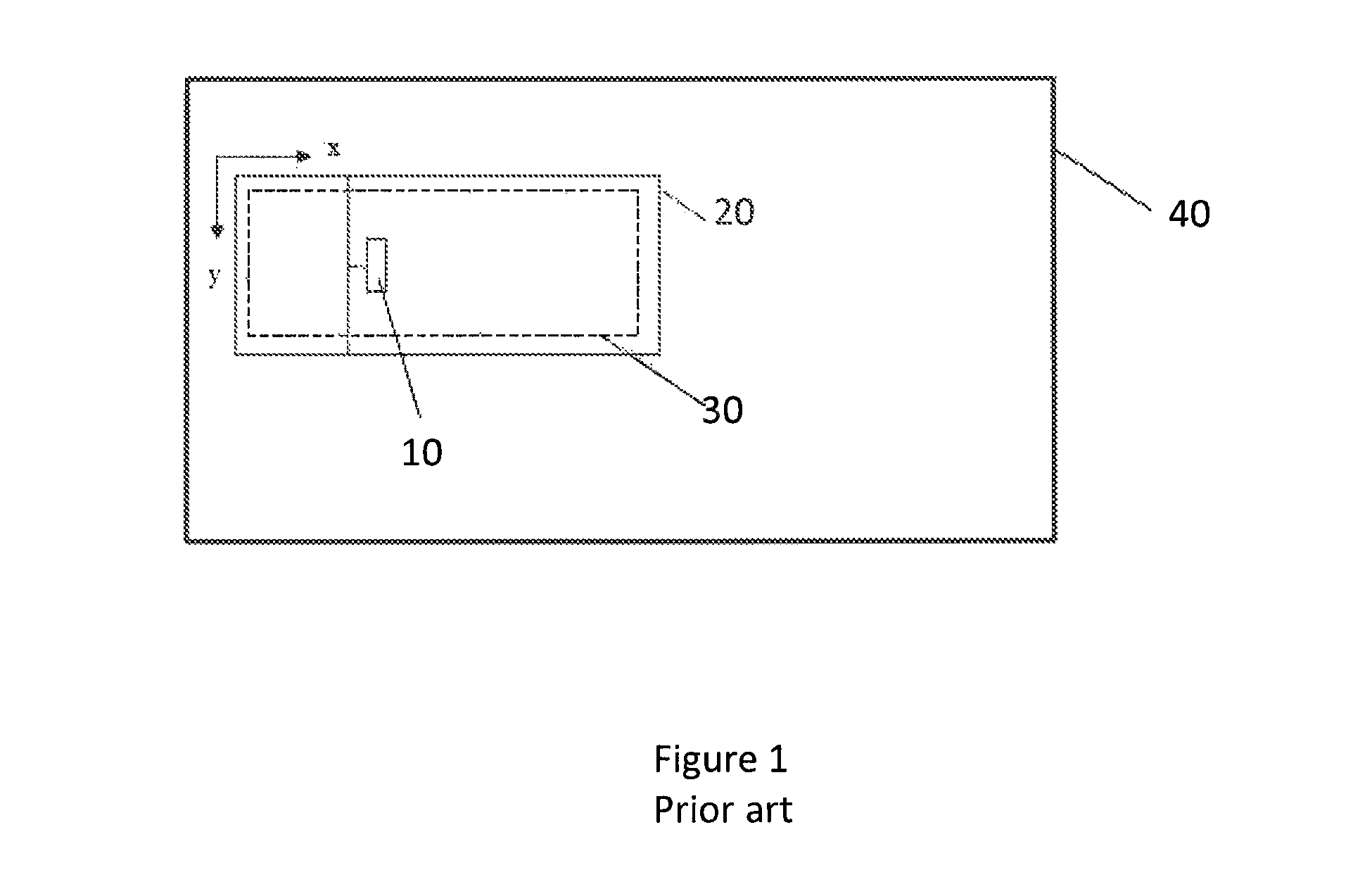
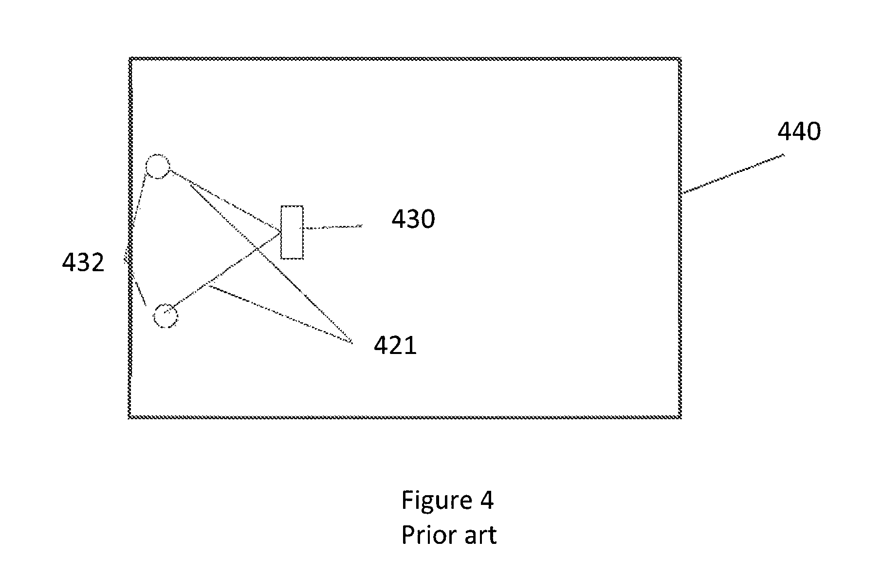
A prior art rectangular scanning support is shown in FIG. 1. A rectangular scanning support 20, supporting a scanning head 10 can be operated on a limited and defined surface. It is cumbersome to install and cannot inspect any area outside of the surface 30 defined by the frame. Thus scanning the entire inspection surface 40 becomes a cumbersome task of piecing together several scans of the limited coverage area 30. A prior art R Theta scanner, having a scanner head 201 and scanner base 230 is shown in FIG. 2. Again, the area to inspect 240 is larger than the coverage area 220. One and two axis prior art string encoders are shown in FIGS. 3 and 4, respectively. In FIG. 3, there is a single spring-loaded string 320 attached to an inspection head 310 and a scanner base 330. Again, the area to inspect 340 is larger than the coverage area. In FIG. 4, there are two spring-loaded strings 421 attached to an inspection head 410 and scanner bases 432. As in the three previous examples, the area to inspect 440 is larger than the device can cover in one positioning of the scanner base.
The inventors have developed a novel system for tracking and displaying the portions of a surface that have been scanned. The solution guarantees that the full surface will be covered with an adequate overlap and that indications are not missing. As the inventive system does not require a fixed reference point on the part under inspection nor any mechanical link between the scanning head and the part to be inspected, it is faster to deploy and does not limit operator agility.
DESCRIPTION
Description of the Drawings
FIG. 1 is a prior art diagram of an are under test by an XY inspection head;
FIG. 2 is a prior art diagram of an area under test by a testing device for use on cylinders;
FIG. 3 is a prior art block diagram of a one axis string encoder;
FIG. 4 is a prior art block diagram of a two axis string encoder;
FIG. 5 is a drawing of an exemplary scanner and an exemplary display; and
FIG. 6 is an exemplary system diagram.
DETAILED SPECIFICATION
As shown in FIG. 6, an inspection head 610, connected to an inspection computer 620 is provided with two position encoders 611, 612. Encoder 1 and 2 provide individual probe end position. Exemplary encoders can be of any kind, for example the known devised using a wheel, an image or time of flight. It is even possible to use dual axis (or more) encoders that give X and Y positions. As the probe is moved across a surface under test, the encoders provide position information that, among other things, is used to produce a display showing the area that has been traversed by the probe. A display is configured to "paint" the area under test with each subsequent area covered by the probe, so that the operator can ensure that the entire surface has been tested by observing the display to see that it is completely covered by the cumulative image produced by the scanner feedback.
To increase precision the system can also use more than two encoders. One possible combination is to use two pairs of two axis wheels (like an omni-wheel) or rolling spheres (like a mouse track ball) in a "X" pattern and have between 2 and 8 encoders positioned on the two axis wheels or rolling spheres.
In an exemplary embodiment, shown in FIGS. 5 and 6, a non-destructive testing (NDT) scanner 510, 610 is fitted with movement encoders 611, 612. In an embodiment, the user must indicate to the system the starting point and initial direction of the scanner relative to the area to inspect. Once the scanner is moving, the encoders provide individual probe end positions allowing the system to calculate probe new position and orientation. If more than two encoders are used, then an average can be calculated for greater precision. FIG. 5 shoes a single scan track 520 in an area to inspect 540. FIG. 6 shows the indication of the scan track on the data acquisition device 620. With many encoders it can also be possible to reject aberrant values. The calculations can take place within the scanner, within the acquisition device or in an intermediate device. Calculations can be performed using any type of calculation device such as and not limited to FGPA, processors, DSP, micro-controllers. The positions and orientations are correlated with the NDT information and plotted on the acquisition device 620 screen as shown in FIG. 6.
By having encoders on two sides of an inspection head, as shown in FIG. 6, it is possible to know the orientation of the head, which does not have to be kept in a rectilinear path, as shown in FIG. 5.
* * * * *
D00000
D00001
D00002
D00003
D00004
D00005
D00006
XML
uspto.report is an independent third-party trademark research tool that is not affiliated, endorsed, or sponsored by the United States Patent and Trademark Office (USPTO) or any other governmental organization. The information provided by uspto.report is based on publicly available data at the time of writing and is intended for informational purposes only.
While we strive to provide accurate and up-to-date information, we do not guarantee the accuracy, completeness, reliability, or suitability of the information displayed on this site. The use of this site is at your own risk. Any reliance you place on such information is therefore strictly at your own risk.
All official trademark data, including owner information, should be verified by visiting the official USPTO website at www.uspto.gov. This site is not intended to replace professional legal advice and should not be used as a substitute for consulting with a legal professional who is knowledgeable about trademark law.