Electric motor test system
Komada , et al.
U.S. patent number 10,295,437 [Application Number 15/313,747] was granted by the patent office on 2019-05-21 for electric motor test system. This patent grant is currently assigned to HORIBA, LTD.. The grantee listed for this patent is HORIBA, Ltd.. Invention is credited to Mineyuki Komada, Kazuhisa Sasahara.

| United States Patent | 10,295,437 |
| Komada , et al. | May 21, 2019 |
Electric motor test system
Abstract
In order to easily and accurately measure the cogging torque of an electric motor, the present invention includes a dynamometer connected to an electric motor, a torque sensor adapted to measure the torque of the electric motor, and a cogging torque measurement motor for measuring the cogging torque of the electric motor, and is configured such that when measuring the cogging torque of the electric motor, the electric motor, the dynamometer, and the cogging torque measurement motor are connected.
| Inventors: | Komada; Mineyuki (Kyoto, JP), Sasahara; Kazuhisa (Kyoto, JP) | ||||||||||
|---|---|---|---|---|---|---|---|---|---|---|---|
| Applicant: |
|
||||||||||
| Assignee: | HORIBA, LTD. (Kyoto,
JP) |
||||||||||
| Family ID: | 55439641 | ||||||||||
| Appl. No.: | 15/313,747 | ||||||||||
| Filed: | August 21, 2015 | ||||||||||
| PCT Filed: | August 21, 2015 | ||||||||||
| PCT No.: | PCT/JP2015/073517 | ||||||||||
| 371(c)(1),(2),(4) Date: | November 23, 2016 | ||||||||||
| PCT Pub. No.: | WO2016/035575 | ||||||||||
| PCT Pub. Date: | March 10, 2016 |
Prior Publication Data
| Document Identifier | Publication Date | |
|---|---|---|
| US 20170191903 A1 | Jul 6, 2017 | |
Foreign Application Priority Data
| Sep 3, 2014 [JP] | 2014-179506 | |||
| Current U.S. Class: | 1/1 |
| Current CPC Class: | G01L 5/13 (20130101); H02K 15/02 (20130101); G01M 15/00 (20130101); G01M 17/0072 (20130101); G01L 3/24 (20130101); G01M 15/02 (20130101) |
| Current International Class: | G01L 3/24 (20060101); G01M 17/007 (20060101); H02K 15/02 (20060101); G01M 15/00 (20060101); G01M 15/02 (20060101); G01L 5/13 (20060101) |
| Field of Search: | ;73/1.09 ;701/114 |
References Cited [Referenced By]
U.S. Patent Documents
| 2520696 | August 1950 | Smith |
| 9205556 | December 2015 | Magnusson |
| 2005/0011288 | January 2005 | Flammer |
| 101000281 | Jul 2007 | CN | |||
| 101387688 | Mar 2009 | CN | |||
| 101458527 | Jun 2009 | CN | |||
| 101753073 | Jun 2010 | CN | |||
| 102829979 | Dec 2012 | CN | |||
| 103808444 | May 2014 | CN | |||
| 102937699 | Jun 2015 | CN | |||
| 06-109565 | Apr 1994 | JP | |||
| 2000-035380 | Feb 2000 | JP | |||
| 2006-220497 | Aug 2006 | JP | |||
| 2009-042137 | Feb 2009 | JP | |||
| 2010-014534 | Jan 2010 | JP | |||
| M275408 | Sep 2005 | TW | |||
| 2013-186871 | Dec 2013 | WO | |||
Other References
|
Poels, P.W.; Cogging Torque Measurement, Moment of Inertia Determination and Sensitivity analysis of Axial Flux Permanent Magnet AC motor; 2008; Technische Universiteit Eindhoven. cited by examiner . International Search Report for Application No. PCT/JP2015/073517, dated Nov. 5, 2015, 3 pgs. cited by applicant . EESR dated Mar. 15, 2018 issued for European Patent Application No. 15 837 808.3. cited by applicant . Official Action dated Apr. 28, 2018 issued for Chinese Patent Application No. 201580026558.X, 15 pgs. cited by applicant. |
Primary Examiner: McCall; Eric S.
Assistant Examiner: Graves; Timothy P
Attorney, Agent or Firm: Brooks Kushman P.C.
Claims
The invention claimed is:
1. An electric motor test system adapted to test performance of an electric motor of a vehicle, the electric motor test system comprising: a dynamometer configured to be connected to the electric motor; a torque sensor configured to measure a torque of the electric motor; a cogging torque measurement motor configured to remain fixed when being connected to and disconnected from the electric motor; and a clutch, between the cogging torque measurement motor and dynamometer, configured to connect the cogging torque measurement motor to the dynamometer along a direction of a rotating axis that transmits a driving power of the dynamometer responsive to a control signal commanding the clutch to switch to a connection state prior to measuring the cogging torque of the electric motor, and disconnect the cogging torque measurement motor from the dynamometer along the direction of the rotating axis that transmits the driving power of the dynamometer responsive to a control signal commanding the clutch to switch to a disconnection state prior to conducting a regular test to test the performance of the electric motor.
2. The electric motor test system according to claim 1, wherein the electric motor is connected to one end side of a rotating shaft of the dynamometer, and the cogging torque measurement motor is connected to the other end side of the rotating shaft.
3. The electric motor test system according to claim 1, wherein the electric motor is connected to one end side of a rotating shaft of the dynamometer, and the cogging torque measurement motor is connected to the one end side of the rotating shaft or to a connecting mechanism connecting the electric motor to the one end side of the rotating shaft.
4. The electric motor test system according to claim 1, wherein the torque sensor is provided on a side of the electric motor rather than the cogging torque measurement motor.
5. The electric motor test system according to claim 1, comprising: a speed reducer that is connected to the cogging torque measurement motor to reduce a rotation speed of the cogging torque measurement motor.
6. The electric motor test system according to claim 1, comprising: a control device configured to generate the control signal commanding the clutch to switch to the connection state, and to generate the control signal commanding the clutch to switch to the disconnection state.
Description
CROSS-REFERENCE TO RELATED APPLICATIONS
This application is the National Stage of International Application No. PCT/JP2015/073517, filed Aug. 21, 2015, which claims priority to JP Patent Application No. 2014-179506, filed Sep. 3, 2014, the disclosures of which are incorporated in their entirety by reference herein.
TECHNICAL FIELD
The present invention relates to an electric motor test system adapted to test the performance of an electric motor mounted in such as an electric vehicle (EV), a hybrid electric vehicle (HEV).
BACKGROUND ART
As this sort of electric motor test system, for example, there is one configured to simulate an actual running state to test the performance of an electric motor by connecting a dynamometer to the electric motor and making the dynamometer function as a driving device or a loading device.
More specifically, in order to simulate the actual running state, it is adapted to measure the torque generated between the electric motor and the dynamometer, and on the basis of the resulting measured value, determine such as a required load to control the dynamometer.
Meanwhile, in the past, when measuring the cogging torque generated in the electric motor in the above-described electric motor test system, it has been adapted to detach the electric motor from the dynamometer, and connect the electric motor to a dedicated cogging torque measurement device as disclosed in, for example, Patent Literature 1 for the measurement.
However, the work to detach the electric motor from the dynamometer and move the electric motor to the cogging torque measurement device for attachment every time for the cogging torque measurement requires alignment such as centering, and this takes much effort and time.
Further, when doing this, if misalignment occurs in such as the centering, the problem of being unable to accurately measure the cogging torque may also occur due to the effect of the misalignment.
CITATION LIST
Patent Literature
Patent Literature 1: Japanese Unexamined Patent Publication JP-A2010-14534
SUMMARY OF INVENTION
Technical Problem
Therefore, the present invention is made in order to solve the above-described problems, and the main object thereof is to, in a system adapted to test the performance of an electric motor using a dynamometer, easily and accurately measure a cogging torque generated in the electric motor.
Solution to Problem
That is, an electric motor test system according to the present invention is an electric motor test system adapted to test the performance of an electric motor of a vehicle, and the electric motor test system includes: a dynamometer that is connected to the electric motor; a torque sensor adapted to measure the torque of the electric motor; and a cogging torque measurement motor for measuring the cogging torque of the electric motor, in which when measuring the cogging torque of the electric motor, the electric motor, the dynamometer, and the cogging torque measurement motor are connected.
In such an electric motor test system, since when measuring the cogging torque of the electric motor, the electric motor, the dynamometer, and the cogging torque measurement motor are connected, by bringing the dynamometer to an unloaded state, the cogging torque can be measured without detaching the electric motor from the dynamometer. This indicates that by preliminarily fixing the electric motor, the dynamometer, and the cogging torque measurement motor so as to make the shaft lines of the mutual rotating shafts thereof coincide, after that, misalignment such as centering is unlikely to occur. Accordingly, by transmitting the rotation of the cogging torque measurement motor to the electric motor, the cogging torque can be easily and accurately measured.
It is preferable that the electric motor is connected to one end side of the rotating shaft of the dynamometer, and the cogging torque measurement motor is connected to the other end side of the rotating shaft. Note that for example, when connecting the cogging torque measurement motor to a shaft connecting the electric motor and the dynamometer, it is necessary to use such as a bevel gear at the connecting point between the shaft and the cogging torque measurement motor. On the other hand, the above-described configuration makes it possible to connect the cogging torque measurement motor to the dynamometer with a simple configuration.
In addition, specific embodiments include one in which the electric motor is connected to the one end side of the rotating shaft of the dynamometer, and the cogging torque measurement motor is connected to the one end side of the rotating shaft or to a connecting mechanism connecting the electric motor to the one end side of the rotating shaft.
This case requires the use of such as a bevel gear as described above, but is advantageous when a space to install the electric motor test system is confined in a direction of the rotating shafts of the electric motor and the dynamometer.
It is preferable that the torque sensor is provided on a side of the electric motor rather than the cogging torque measurement motor.
In doing so, in a state where the rotation of the cogging torque measurement motor is transmitted to the electric motor, the measured torque measured by the torque sensor is measured as the cogging torque, and in a state where the rotation of the dynamometer is transmitted to the electric motor, measured as a regular test torque used to test the performance of the electric motor. That is, the torque sensor can be used for both the cogging torque measurement and the regular test torque measurement to thereby eliminate the need for a dedicated torque sensor for measuring the cogging torque.
It is preferable to further include a connecting/disconnecting mechanism provided between the cogging torque measurement motor and the dynamometer, in which the connecting/disconnecting mechanism, when measuring the cogging torque of the electric motor, connects the cogging torque measurement motor to the dynamometer, and when doing a regular test to test the performance of the electric motor, disconnects the cogging torque measurement motor from the dynamometer.
In doing so, although when rotating at high speed, the cogging torque measurement motor may be damaged, by disconnecting the cogging torque measurement motor from the dynamometer when doing the regular test, high speed rotation of the dynamometer can be prevented from transmitting to the cogging torque measurement motor, and thereby the cogging torque measurement motor can be prevented from being damaged.
It is preferable to include a speed reducer that is connected to the cogging torque measurement motor to reduce the rotation speed of the cogging torque measurement motor.
In doing so, rotation stability in low rotation speed performance required for the cogging torque measurement motor can be improved.
Advantageous Effects of Invention
According to the present invention configured as described, without moving the electric motor, the need for alignment such as centering, which has been required in the past whenever measuring cogging toque, can be eliminated and the cogging torque of the electric motor can be easily and accurately measured.
BRIEF DESCRIPTION OF DRAWINGS
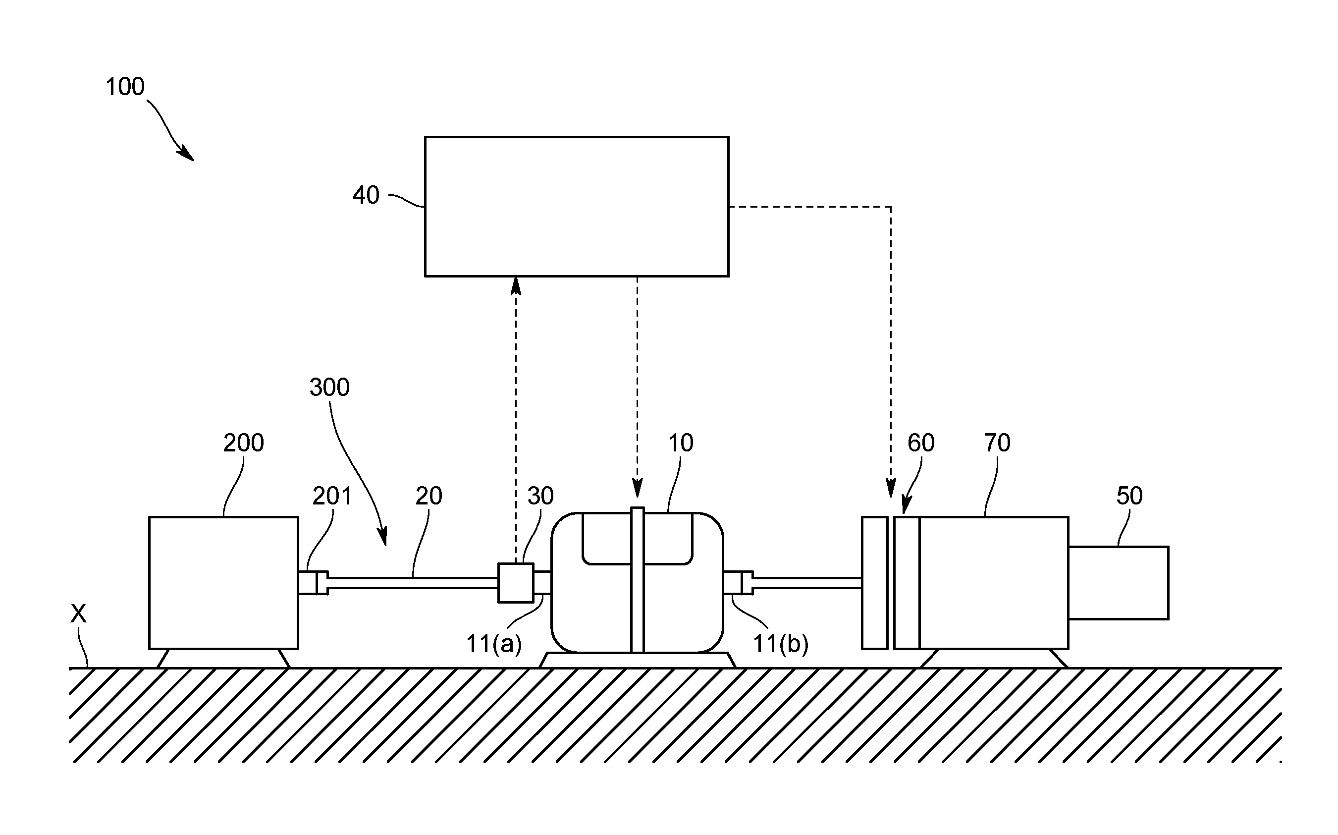
FIG. 1 is a diagram schematically illustrating an overall configuration of an electric motor test system of the present embodiment.
FIG. 2 is a diagram schematically illustrating an overall configuration of an electric motor test system of a variation.
FIG. 3 is a diagram schematically illustrating an overall configuration of an electric motor test system of a variation.
REFERENCE SIGNS LIST
100 Electric motor test system 200 Electric motor 10 Dynamometer 20 Connecting mechanism 300 Rotation transmitting system 30 Torque sensor 50 Cogging torque measurement motor 60 Connecting/disconnecting mechanism
DESCRIPTION OF EMBODIMENTS
In the following, one embodiment of an electric motor test system according to the present invention will be described with reference to the drawings.
An electric motor test system 100 according to the present embodiment is one that tests such as the operating performance of an electric motor 200 of an electric vehicle or a hybrid vehicle on a test bench, and as illustrated in FIG. 1, configured to include: a dynamometer 10 connected to the electric motor 200; a connecting mechanism 20 adapted to connect the rotating shaft 201 of the electric motor 200 and the rotating shaft 11 of the dynamometer 10; a torque sensor 30 adapted to measure a torque generated between the electric motor 200 and the dynamometer 10; and a control device 40 adapted to receive an output from the torque sensor 30.
Note that in the present embodiment, the electric motor 200 and the dynamometer 10 are placed and fixed on, for example, a floor or a base X.
The dynamometer 10 is one that performs a test run of the electric motor 200, and depending on a state of the test run, works as an electric motor and thereby functions as a driving device for driving the electric motor 200, or works as an electric generator and thereby functions as a loading device for placing a load on the electric motor 200.
Specifically, the dynamometer 10 is an AC electric dynamometer including an unillustrated electric motor as an AC motor, and in the present embodiment, as illustrated in FIG. 1, one of a both-end drive type configured to be able to output powers from one end side 11a and the other end side 11bof the rotating shaft 11.
The connecting mechanism 20 is one that mechanically connects the rotating shaft 201 of the electric motor 200 and the rotating shaft 11 of the dynamometer 10, and specifically, includes such as a shaft connected to the rotating shaft 201 of the electric motor 200 and the one end side 11a of the rotating shaft 11 of the dynamometer 10, a coupling connecting the shaft and the rotating shaft 201, a coupling connecting the shaft and the one end side 11a. Alternatively, as the connecting mechanism 20, such as a gear may be used.
With the above-described configuration, the rotating shaft 201 of the electric motor 200, the rotating shaft 11 of the dynamometer 10, and the connecting mechanism 20 mechanically connecting them rotate with the shaft lines thereof made to coincide, and constitute a rotation transmitting system 300. Note that the rotation transmitting system 300 has the rotating shaft 201 of the electric motor 200, the rotating shaft 11 of the dynamometer 10, and the connecting mechanism 20 connecting the electric motor 200 and the dynamometer 10, and in the present embodiment, further has a connecting mechanism including such as a shaft, a coupling connected to the other end side 11b of the rotating shaft 11 of the dynamometer 10.
The torque sensor 30 is one that is connected to the rotation transmitting system 300 to measure the torque of the electric motor 200, and outputs a measurement signal indicating the resulting measured value to the control device 40, and here, as the torque sensor 30, for example, one of a flange type is used.
Note that as the torque sensor 30, ones of various types such as a contact type and a noncontact type may be used.
The control device 40 is one that receives the measurement signal from the above-described torque sensor 30, on the basis of the torque indicated by the measurement signal, calculates such as a load placed on the electric motor 200, and controls the dynamometer 10 so as to bring the electric motor 200 to a predetermined test run state.
In addition, as illustrated in FIG. 1, in order to measure the cogging torque of the electric motor 200, the electric motor test system 100 of the present embodiment further includes a cogging torque measurement motor 50 that is connected to the above-described rotation transmitting system 300 in a disconnectable manner, and rotates the rotating shaft 201 of the electric motor 200 to generate the cogging torque.
The cogging torque measurement motor 50 is fixed to the base X and also provided on a side of the dynamometer 10 rather than the above-described torque sensor 30 through a connecting/disconnecting mechanism 60 and a speed reducer 70. In the present embodiment, the cogging torque measurement motor 50 is connected to the other end side 11bof the rotating shaft 11 of the above-described dynamometer 10, and specifically a low rotation speed motor adapted to rotate the rotating shaft 201 of the electric motor 200 at low speed having a predetermined rotation speed.
Note that the cogging torque measurement motor 50 may be one adapted to perform angle control of the rotating axis 201 of the electric motor 200. In this case, as the cogging torque measurement motor 50, one configured to alternately repeat a rotating state of rotating the rotating shaft 201 by a predetermined angle and a halting state of halting the rotating shaft 201 for a predetermined time can be cited.
The connecting/disconnecting mechanism 60 is one that is provided between the cogging torque measurement motor 50 and the dynamometer 10, and receives a control signal from the control device 40 to switch between a connection state of connecting the cogging torque measurement motor 50 to the rotation transmitting system 300 and a disconnection state of disconnecting the cogging torque measurement motor 50 from the rotation transmitting system 300. The connecting/disconnecting mechanism 60 in the present embodiment is connected to the other end side 11b of the rotating shaft 11 of the dynamometer 10 through the shaft, and specifically, configured using a clutch mechanism such as an electromagnetic clutch.
The speed reducer 70 is one that reduces the rotation speed of the cogging torque measurement motor 50 at a predetermined speed reduction ratio (e.g., 1/100 or 1/1000), and in the present embodiment, placed and fixed on the base X and also provided between the cogging torque measurement motor 50 and the connecting/disconnecting mechanism 60.
The above-described arrangement makes it possible to connect/disconnect the speed reducer 70 to/from the rotation transmitting system 300 together with the cogging torque measurement motor 50 because the connecting/disconnecting mechanism 60 is provided between the dynamometer 10 and the speed reducer 70.
Subsequently, the actions of the electric motor test system 100 of the present embodiment will be described.
First, the rotation transmitting system 300 and the cogging torque measurement motor 50 are arranged fixed on the base X so as to make the shaft lines of the rotating shafts thereof coincide.
Next, the regular test time for the electric motor test system 100 to test the performance of the electric motor 200 will be described.
When doing a regular test, the connecting/disconnecting mechanism 60 receives a control signal from the control device 40 to switch to the disconnection state, and disconnects the cogging torque measurement motor 50 from the rotation transmitting system 300. Note that when doing this, it is preferable to power off the cogging torque measurement motor.
In the disconnection state, the torque sensor 30 measures the torque generated between the electric motor 200 and the dynamometer 10, and outputs a measurement signal indicating the measured torque to the control device 40.
The control device 40 acquires the torque indicated by the measurement signal as a regular test torque, and on the basis of the regular test torque, controls the dynamometer 10 to make the dynamometer 10 function as the driving device or the loading device.
This makes it possible to bring the electric motor 200 to the predetermined test run state and test the operating performance of the electric motor 200.
Subsequently, the cogging torque measurement time for the electric motor test system 100 to measure the cogging torque generated in the electric motor 200 will be described.
When measuring the cogging torque, the connecting/disconnecting mechanism 60 receives a control signal from the control device 40 to switch to the connection state, and connects the cogging torque measurement motor 50 to the rotation transmitting system 300.
In the connection state, by bringing the dynamometer 10 to an unloaded state, the dynamometer 10 is made free, and therefore the cogging torque measurement motor 50 rotates the electric motor 200 at low speed.
At this time, the torque sensor 30 measures the torque generated in such a way that the cogging torque measurement motor 50 rotates the electric motor 200, and outputs a measurement signal indicating the measured torque to the control device 40.
As a result, the control device 40 can acquire the torque indicated by the measurement signal as the cogging torque of the electric motor 200.
In the electric motor test system 100 according to the present embodiment configured as described, since the cogging torque measurement motor 50 and the rotation transmitting system 300 are preliminarily arranged fixed on the base X so as to make the shaft lines of the rotating shafts thereof coincide, when switching the connecting/disconnecting mechanism 60, misalignment such as centering having occurred in the past is unlikely to occur. As a result, by switching the connecting/disconnecting mechanism 60 to the connection state to connect the cogging torque measurement motor 50 to the rotation transmitting system 300, the cogging torque can be easily and accurately measured.
In addition, when doing the regular test to test the performance of the electric motor 200, by disconnecting the cogging torque measurement motor 50 from the rotation transmitting system 300, the rotation of the dynamometer 10 is not transmitted to the cogging torque measurement motor 50, and therefore the cogging torque measurement motor 50 can be prevented from rotating at high speed to get damaged.
Also, since the electric motor test system 100 includes the speed reducer 70 adapted to reduce the rotation speed of the cogging torque measurement motor 50, low rotation speed performance required for the cogging torque measurement motor 50 can be relaxed.
Further, even if the speed reducer 70 is one having a low allowable rotation speed, the connecting/disconnecting mechanism 60 is provided between the speed reducer 70 and the dynamometer 10, and therefore when doing the regular test, the connecting/disconnecting mechanism 60 can disconnect the speed reducer 70 and the rotation transmitting system 300 from each other to prevent the rotation of the dynamometer 10 from transmitting to the speed reducer 70, thus being secure against damaging the speed reducer 70.
In addition, since the torque sensor 30 is provided between the shaft and the one end side 11a of the rotating shaft 11 of the dynamometer 10, a dedicated part for attaching the torque sensor 30 to such as the shaft is not required, thus making it possible to simplify a configuration.
Note that the present invention is not limited to the above-described embodiment.
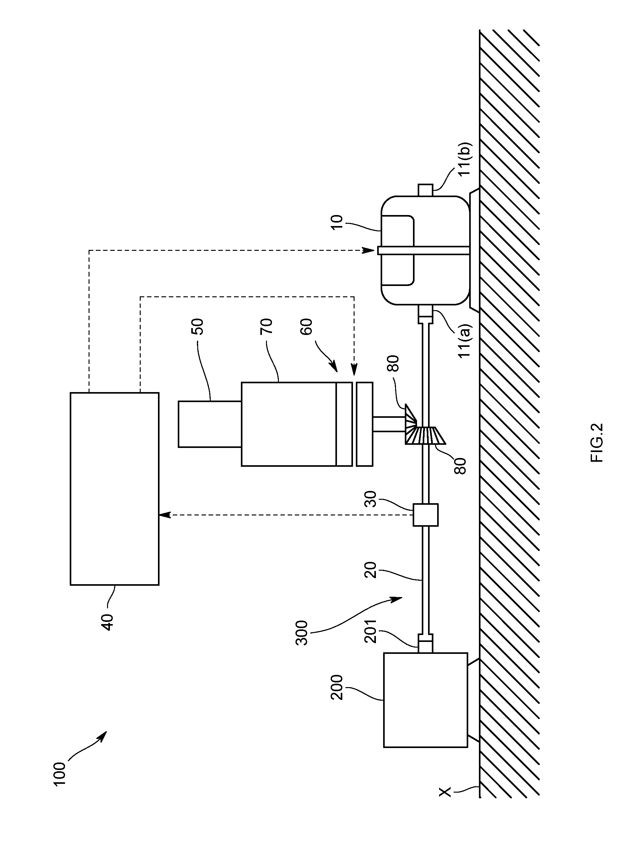
For example, in the above-described embodiment, the cogging torque measurement motor 50 is connected to the other end side 11b of the rotating shaft 11 of the dynamometer 10 through the connecting/disconnecting mechanism 60 and the speed reducer 70; however, as illustrated in FIG. 2, the cogging torque measurement motor 50 may be connected to the one end side 11a of the rotating shaft 11 of the dynamometer 10 through the connecting/disconnecting mechanism 60 and the speed reducer 70.
Specifically, as illustrated in FIG. 2, a configuration in which the connecting/disconnecting mechanism 60 is connected to the connecting mechanism 20 (specifically, the shaft) through, for example, such as a bevel gear 80 can be cited.
In this case, it is only necessary that the torque sensor 30 provided to the connecting mechanism 20 is positioned on a side of the electric motor 200 rather than the connecting point between the connecting mechanism 20 and the connecting/disconnecting mechanism 60.
Also, the connecting/disconnecting mechanism 60 in the above-described embodiment is provided between the dynamometer 10 and the speed reducer 70; however, for example, as illustrated in FIG. 3, the connecting/disconnecting mechanism 60 may be provided between the speed reducer 70 and the cogging torque measurement motor 50.
Further, the torque sensor 30 in the above-described embodiment is one of a fixed type, but may be one of, for example, an oscillating type attached to the dynamometer 10.
Still further, as the dynamometer 10 in the above-described embodiment, one of an AC type is used, but one of, for example, a DC type may be used.
In addition, the connecting/disconnecting mechanism 60 in the above-described embodiment is one having the clutch mechanism such as an electromagnetic clutch, but without limitation to the electromagnetic clutch, only required to be one capable of mechanically connecting or disconnecting the cogging torque measurement motor 50 to or from the rotation transmitting system 300.
Also, it is not necessarily required to include the connecting/disconnecting mechanism 60 and the speed reducer 70 in the above-described embodiment.
Further, the cogging torque of the dynamometer 10 may be measured using the electronic motor test system 100 of the above-described embodiment. In this case, it is only necessary to bring the electric motor 200 to an unloaded state. In addition, the torque sensor 30 may be provided between the dynamometer 10 and the cogging torque measurement motor 50.
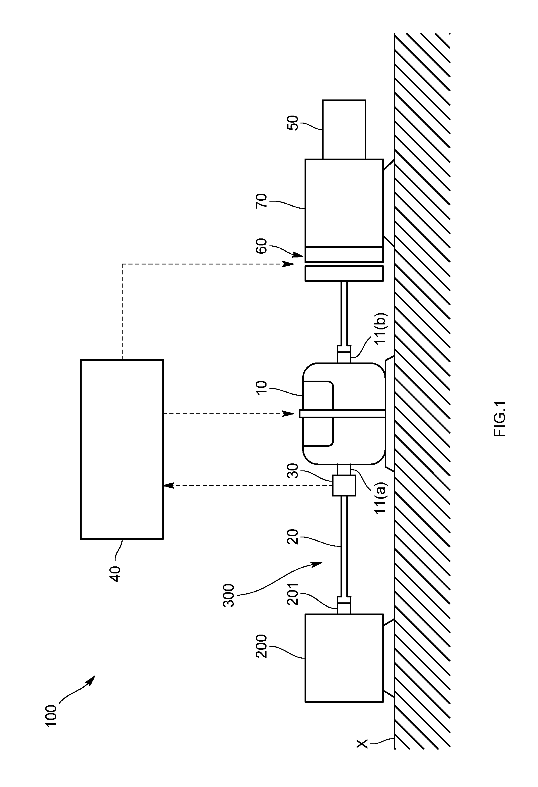
Note that the above-described embodiment can also be applied to the electric motor test system 100 illustrated in FIG. 2 in the same manner.
In addition, the electric motor test system 100 of the above-described embodiment may be one adapted to test the performance of an electric motor mounted in a fuel cell vehicle (FCV).
Besides, it should be appreciated that the present invention is not limited to any of the above-described embodiment and variations, but can be variously modified without departing the scope thereof.
INDUSTRIAL APPLICABILITY
According to the present invention, without moving the electric motor, the need for alignment such as centering, which has been required in the past whenever measuring cogging toque, can be eliminated and the cogging torque of the electric motor can be easily and accurately measured.
* * * * *
D00000
D00001
D00002
D00003
XML
uspto.report is an independent third-party trademark research tool that is not affiliated, endorsed, or sponsored by the United States Patent and Trademark Office (USPTO) or any other governmental organization. The information provided by uspto.report is based on publicly available data at the time of writing and is intended for informational purposes only.
While we strive to provide accurate and up-to-date information, we do not guarantee the accuracy, completeness, reliability, or suitability of the information displayed on this site. The use of this site is at your own risk. Any reliance you place on such information is therefore strictly at your own risk.
All official trademark data, including owner information, should be verified by visiting the official USPTO website at www.uspto.gov. This site is not intended to replace professional legal advice and should not be used as a substitute for consulting with a legal professional who is knowledgeable about trademark law.