Quenched steel sheet having excellent strength and ductility
Park , et al.
U.S. patent number 10,294,541 [Application Number 15/101,384] was granted by the patent office on 2019-05-21 for quenched steel sheet having excellent strength and ductility. This patent grant is currently assigned to POSCO. The grantee listed for this patent is POSCO. Invention is credited to Jae-Hoon Jang, Kyong-Su Park.

| United States Patent | 10,294,541 |
| Park , et al. | May 21, 2019 |
Quenched steel sheet having excellent strength and ductility
Abstract
Disclosed are a quenched steel sheet and a method for manufacturing the same. The quenched steel sheet according to an aspect of the present invention contains, in terms of wt %, C: 0.05.about.0.25%, Si: 0.5% or less (excluding 0), Mn: 0.1.about.2.0%, P: 0.05% or less, S: 0.03% or less, the remainder Fe, and other unavoidable impurities, wherein a refined structure of the steel sheet comprises 90 volume % or more of martensite with a first hardness and martensite with a second hardness.
| Inventors: | Park; Kyong-Su (Pohang-si, KR), Jang; Jae-Hoon (Pohang-si, KR) | ||||||||||
|---|---|---|---|---|---|---|---|---|---|---|---|
| Applicant: |
|
||||||||||
| Assignee: | POSCO (Pohang-si,
Gyeongsangbuk-do, KR) |
||||||||||
| Family ID: | 53479046 | ||||||||||
| Appl. No.: | 15/101,384 | ||||||||||
| Filed: | December 24, 2013 | ||||||||||
| PCT Filed: | December 24, 2013 | ||||||||||
| PCT No.: | PCT/KR2013/012132 | ||||||||||
| 371(c)(1),(2),(4) Date: | June 02, 2016 | ||||||||||
| PCT Pub. No.: | WO2015/099214 | ||||||||||
| PCT Pub. Date: | July 02, 2015 |
Prior Publication Data
| Document Identifier | Publication Date | |
|---|---|---|
| US 20160348207 A1 | Dec 1, 2016 | |
Foreign Application Priority Data
| Dec 23, 2013 [KR] | 10-2013-0161430 | |||
| Current U.S. Class: | 1/1 |
| Current CPC Class: | C21D 8/0436 (20130101); C21D 1/18 (20130101); C21D 8/0236 (20130101); C22C 38/00 (20130101); C21D 8/0447 (20130101); C21D 8/0473 (20130101); C21D 9/46 (20130101); C21D 8/021 (20130101); C22C 38/002 (20130101); C22C 38/02 (20130101); C21D 8/02 (20130101); C22C 38/04 (20130101); C21D 2201/00 (20130101); C21D 2211/005 (20130101); C21D 2211/001 (20130101); C21D 2211/008 (20130101); C21D 2211/009 (20130101) |
| Current International Class: | C22C 38/02 (20060101); C22C 38/00 (20060101); C21D 8/02 (20060101); C21D 9/46 (20060101); C22C 38/04 (20060101); C21D 8/04 (20060101); C21D 1/18 (20060101) |
References Cited [Referenced By]
U.S. Patent Documents
| 8480824 | July 2013 | Cola, Jr. et al. |
| 2004/0238081 | December 2004 | Yoshinaga et al. |
| 2007/0261770 | November 2007 | Cola et al. |
| 2009/0252641 | October 2009 | Hoshi et al. |
| 2010/0051146 | March 2010 | Park et al. |
| 2010/0132854 | June 2010 | Cola, Jr. |
| 2010/0163140 | July 2010 | Cola, Jr. |
| 2012/0042994 | February 2012 | Fujita et al. |
| 2012/0175028 | July 2012 | Matsuda et al. |
| 2013/0048151 | February 2013 | Kawamura et al. |
| 2015/0050519 | February 2015 | Nonaka et al. |
| 1547620 | Nov 2004 | CN | |||
| 1692166 | Nov 2005 | CN | |||
| 1486574 | Dec 2004 | EP | |||
| 2581465 | Apr 2013 | EP | |||
| 3-087320 | Apr 1991 | JP | |||
| 2006-70328 | Mar 2006 | JP | |||
| 2008-255469 | Oct 2008 | JP | |||
| 2010-065272 | Mar 2010 | JP | |||
| 2010-174280 | Aug 2010 | JP | |||
| 2010-196106 | Sep 2010 | JP | |||
| 2011-47034 | Mar 2011 | JP | |||
| 2011-52295 | Mar 2011 | JP | |||
| 2011-179030 | Sep 2011 | JP | |||
| 2011-202207 | Oct 2011 | JP | |||
| 2013-76155 | Apr 2013 | JP | |||
| 0270395 | Aug 2000 | KR | |||
| 10-0716342 | May 2007 | KR | |||
| 2007-0086335 | Aug 2007 | KR | |||
| 10-2007-0099693 | Oct 2007 | KR | |||
| 0782785 | Nov 2007 | KR | |||
| 10-1054773 | Aug 2011 | KR | |||
| 10-2013-0016433 | Feb 2013 | KR | |||
| 10-2013-0096213 | Aug 2013 | KR | |||
| 2013/105631 | Jul 2013 | WO | |||
Other References
|
Machine-English translation of JP 2013-076155 A, Sugimot Koichi et al., Apr. 25, 2013. cited by examiner . International Search Report dated Sep. 29, 2014 issued in International Patent Application No. PCT/KR2013/012132 (English translation). cited by applicant . Chinese Office Action dated Feb. 20, 2017 issued in Chinese Patent Application No. 201380081843.2 (with English translation). cited by applicant . Japanese Office Action dated Aug. 22, 2017 issued in Japanese Patent Application No. 2016-542201. cited by applicant . Extended European Search Report dated Nov. 23, 2016 issued in European Patent Application No. 13900181.2. cited by applicant. |
Primary Examiner: Yee; Deborah
Attorney, Agent or Firm: Morgan Lewis & Bockius LLP
Claims
The invention claimed is:
1. A quenched steel sheet comprising, by wt %, carbon (C): 0.05% to 0.25%, silicon (Si): 0.5% or less (with the exception of 0), manganese (Mn): 0.1% to 2.0%, phosphorus (P): 0.05% or less, sulfur (S): 0.03% or less, iron (Fe) as a residual component thereof, and other unavoidable impurities, wherein the quenched steel sheet includes 90 volume % or more of martensite having a first hardness and martensite having a second hardness as a microstructure of the steel, wherein the martensite having the first hardness and the martensite having the second hardness as a microstructure are formed in an entire area of the steel sheet, wherein the first hardness has a greater hardness value than a hardness value of the second hardness, and a ratio of a difference between the first hardness and the second hardness to the first hardness satisfies relational expression 1, 5.ltoreq.(first hardness-second hardness)/(first hardness)*100.ltoreq.30, and [Relational Expression 1] wherein average packet sizes of the martensite having the first hardness and the martensite having the second hardness are 20 .mu.m or less.
2. The quenched steel sheet of claim 1, wherein a tensile strength of the steel sheet is 1200 MPa or more, and elongation of the steel sheet is 7% or more.
3. A quenched steel sheet provided by cold rolling and heat treating a steel sheet comprising, by wt %, carbon (C): 0.05% to 0.25%, silicon (Si): 0.5% or less (with the exception of 0), manganese (Mn): 0.1% to 2.0%, phosphorus (P): 0.05% or less, sulfur (S): 0.03% or less, iron (Fe) as a residual component thereof, and other unavoidable impurities, and comprising ferrite and pearlite as a microstructure, wherein the microstructure of the quenched steel sheet includes 90 volume % or more of martensite having a first hardness and martensite having a second hardness, the martensite having the first hardness is provided through transformation occurring from pearlite before heat treatment and in a region adjacent to the pearlite before heat treatment, and the martensite having the second hardness is provided through transformation occurring from ferrite before heat treatment and in a region adjacent to the ferrite before heat treatment, wherein the martensite having the first hardness and the martensite having the second hardness as a microstructure are formed in an entire area of the steel sheet, wherein the first hardness has a greater hardness value than a hardness value of the second hardness, and a ratio of a difference between the first hardness and the second hardness to the first hardness satisfies relational expression 1, 5.ltoreq.(first hardness-second hardness)/(first hardness)*100.ltoreq.30, and [Relational Expression 1] wherein average packet sizes of the martensite having the first hardness and the martensite having the second hardness are 20 .mu.m or less.
4. The quenched steel sheet of claim 3, wherein a tensile strength of the steel sheet is 1200 MPa or more, and elongation of the steel sheet is 7% or more.
Description
RELATED APPLICATIONS
This application is the U.S. National Phase under 35 U.S.C. .sctn. 371 of International Application No. PCT/KR2013/012132, filed on Dec. 24, 2013, which in turn claims the benefit of Korean Patent Application No. 10-2013-0161430 filed on Dec. 23, 2013, the disclosure of which applications are incorporated by reference herein.
TECHNICAL FIELD
The present disclosure relates to a quenched steel plate having excellent strength and ductility and a method of manufacturing the same.
BACKGROUND ART
In terms of steel, strength and ductility are inversely related, and the following technologies according to the related art are used as methods of obtaining steel having excellent strength and ductility.
As representative examples, there are technologies of controlling a phase fraction of a ferrite, bainite, or martensite structure such as dual phase (DP) steel disclosed in Korean Patent Publication No. 0782785, transformation induced plasticity (TRIP) steel disclosed in Korean Patent Publication No. 0270396, as well as controlling a residual austenite fraction by utilizing an alloying element such as manganese (Mn), nickel (Ni), or the like disclosed in Korean Patent Publication No. 1054773.
However, in a case of DP steel or TRIP steel, increases in strength are limited to 1200 MPa. In addition, in the case of a technology of controlling a residual austenite fraction, increases in strength are limited to 1200 MPa, and there may be a problem of increased manufacturing costs due to the addition of a relatively expensive alloying element.
Thus, the development of a steel in which relatively expensive alloying elements may be used in significantly reduced amounts and excellent strength and ductility may be provided is required.
DISCLOSURE
Technical Problem
An aspect of the present disclosure may provide a quenched steel sheet having excellent strength and ductility without adding a relatively expensive alloying element by properly controlling an alloy composition and heat treatment conditions, and a method of manufacturing the same.
Technical Solution
According to an aspect of the present disclosure, a quenched steel sheet may be a steel plate including, by wt %, carbon (C): 0.05% to 0.25%, silicon (Si): 0.5% or less (with the exception of 0), manganese (Mn): 0.1% to 2.0%, phosphorus (P): 0.05% or less, sulfur (S): 0.03% or less, iron (Fe) as a residual component thereof, and other unavoidable impurities. The quenched steel sheet may include 90 volume % or more of martensite having a first hardness and martensite having a second hardness as a microstructure of the steel plate. The first hardness may have a greater hardness value than a hardness value of the second hardness, and a ratio of a difference between the first hardness and the second hardness and the first hardness may satisffy relational expression 1. 5.ltoreq.(first hardness-second hardness)/(first hardness)*100.ltoreq.30 [Relational Expression 1]
According to another aspect of the present disclosure, a quenched steel sheet may be a quenched steel sheet provided by cold rolling and heat treating a steel plate including, by wt %, carbon (C): 0.05% to 0.25%, silicon (Si): 0.5% or less (with the exception of 0), manganese (Mn): 0.1% to 2.0%, phosphorus (P): 0.05% or less, sulfur (S): 0.03% or less, iron (Fe) as a residual component thereof, and other unavoidable impurities, and including ferrite and pearlite as a microstructure. The microstructure of the quenched steel sheet includes 90 volume % or more of martensite having a first hardness and martensite having a second hardness. The martensite having the first hardness is provided through transformation occurring from pearlite before heat treatment and in a region adjacent to the pearlite before heat treatment, and the martensite having the second hardness is provided through transformation occurring from ferrite before heat treatment and in a region adjacent to the ferrite before heat treatment.
According to another aspect of the present disclosure, a method of manufacturing a quenched steel sheet according to an exemplary embodiment in the present disclosure may include: cold rolling a steel plate including, by wt %, carbon (C): 0.05% to 0.25%, silicon (Si): 0.5% or less (with the exception of 0), manganese (Mn): 0.1% to 2.0%, phosphorus (P): 0.05% or less, sulfur (S): 0.03% or less, iron (Fe) as a residual component thereof, and other unavoidable impurities, and including ferrite and pearlite as a microstructure at a reduction ratio of 30% or more; heating the cold-rolled steel plate to a heating temperature (T*) of Ar3.degree. C. to Ar3+500.degree. C.; and cooling the heated steel plate. A heating rate (v.sub.r, .degree. C./sec) satisfies relational expression 2 when heating the steel plate, and a cooling rate (v.sub.c, .degree. C./sec) satisfies relational expression 3 when cooling the steel plate. v.sub.r.gtoreq.(T*/110).sup.2 [Relational Expression 2] v.sub.c.gtoreq.(T*/80).sup.2 [Relational Expression 3]
Advantageous Effects
According to an exemplary embodiment in the present disclosure, a quenched steel sheet having excellent strength and ductility, of which a tensile strength is 1200 MPa or more and elongation is 7% or more without adding a relatively expensive alloying element, may be provided.
DESCRIPTION OF DRAWINGS
FIG. 1 illustrates a microstructure of a steel plate before heat treatment, observed with an electron microscope, according to an exemplary embodiment in the present disclosure.
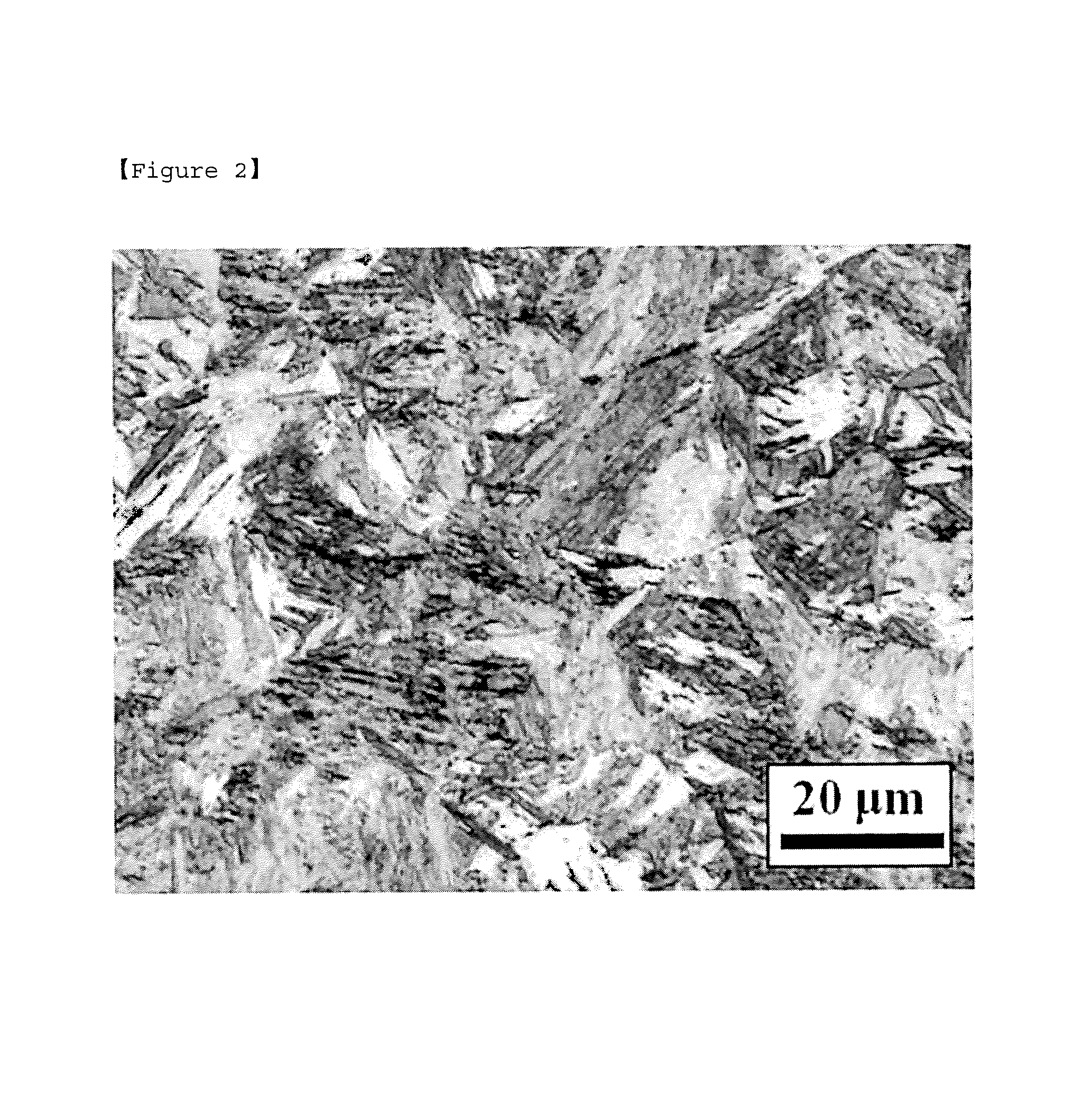
FIG. 2 illustrates a microstructure, observed with an optical microscope, of a steel plate after heat treatment of inventive example 4 meeting conditions of an exemplary embodiment in the present disclosure.
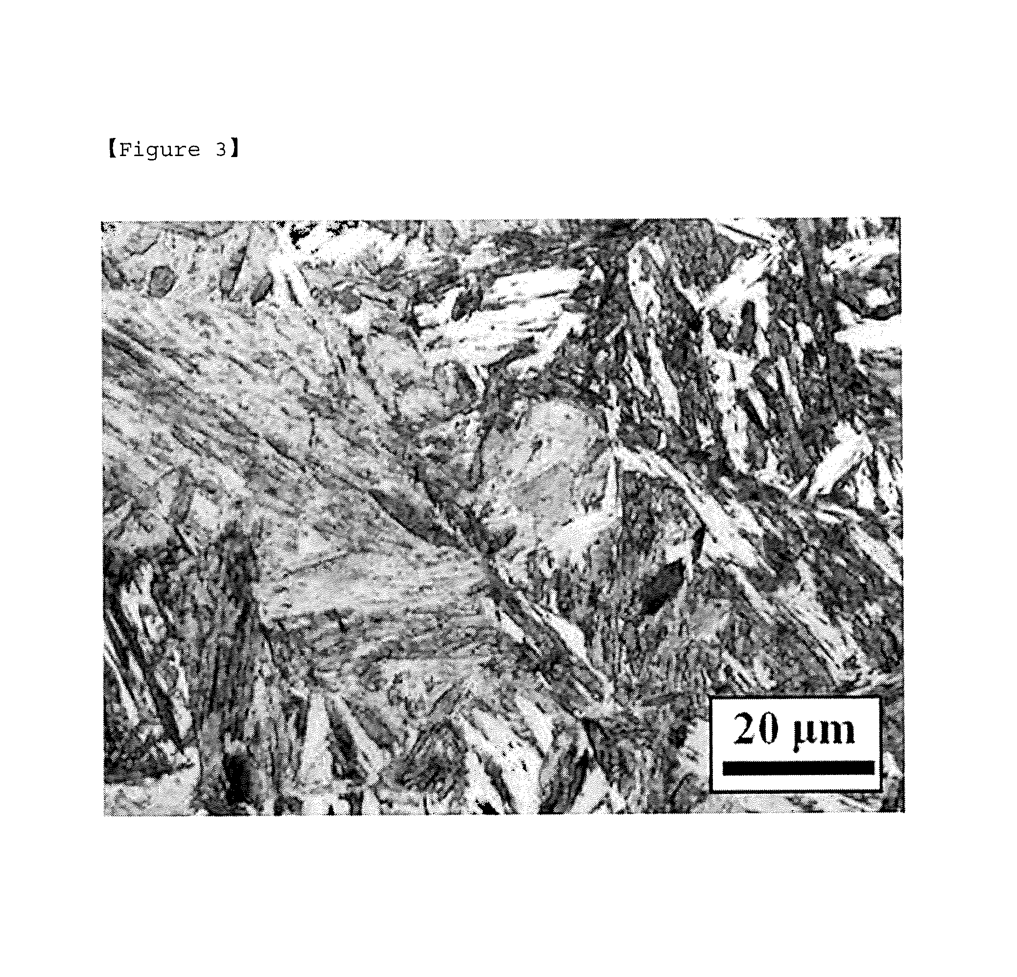
FIG. 3 illustrates a microstructure, observed with an optical microscope, of a steel plate after heat treatment of comparative example 5 under conditions other than those of an exemplary embodiment in the present disclosure.
BEST MODE FOR INVENTION
The inventors have conducted research to solve problems of the above described related art. As a result, a carbon content may be properly provided and cold rolling and a heat treatment process may be properly controlled in the present disclosure, thereby forming two kinds of martensite having different levels of hardness as a microstructure of a steel plate. Thus, a steel plate capable of having improved strength and ductility without adding a relatively expensive alloying element may be provided.
Hereafter, a quenched steel sheet having excellent strength and ductility according to an exemplary embodiment in the present disclosure will be described in detail. In the present disclosure, `heat treatment` means heating and cooling operations carried out after cold rolling.
First, an alloy composition of a quenched steel sheet according to an exemplary embodiment in the present disclosure is described in detail.
Carbon (C): 0.05 wt % to 0.25 wt %
Carbon is an essential element for improving the strength of a steel plate, and carbon may be required to be added in a proper amount to secure martensite which is required to be implemented in the present disclosure. In a case in which the content of C is less than 0.05 wt %, it may be difficult not only to obtain sufficient strength of a steel plate, but also to secure a martensite structure of 90 volume % or more as a microstructure of a steel plate after heat treatment. On the other hand, in a case in which the content of C exceeds 0.25 wt %, ductility of the steel plate may be decreased. In the present disclosure, the content of C may be properly controlled within a range of 0.05 wt % to 0.25 wt %.
Silicon (Si): 0.5 wt % (with the Exception of 0)
Si may serve as a deoxidizer, and may serve to improve strength of a steel plate. In a case in which the content of Si exceeds 0.5 wt %, scale may be formed on a surface of the steel plate in a case in which the steel plate is hot-rolled, thereby degrading surface quality of the steel plate. In the present disclosure, the content of Si may be properly controlled to be 0.5 wt % or less (with the exception of 0).
Manganese (Mn): 0.1 wt % to 2.0 wt %
Mn may improve strength and hardenability of steel, and Mn may be combined with S, inevitably contained therein during a steel manufacturing process to then form MnS, thereby serving to suppress the occurrence of crack caused by S. In order to obtain the effect in the present disclosure, the content of Mn may be 0.1 wt % or more. On the other hand, in a case in which the content of Mn exceeds 2.0 wt %, toughness of steel may be decreased. In the present disclosure, thus, the content of Mn may be controlled to be within a range of 0.1 wt % to 2.0 wt %.
Phosphorus (P): 0.05 wt % or Less
P is an impurity inevitably contained in steel, and P is an element that is a main cause of decreasing ductility of steel as P is organized in a grain boundary. Thus, a content of P may be properly controlled to be as relatively low. Theoretically, the content of P may be advantageously limited to be 0%, but P is inevitably provided during a manufacturing process. Thus, it may be important to manage an upper limit thereof. In the present disclosure, an upper limit of the content of P may be managed to be 0.05 wt %.
Sulfur (S): 0.03 wt % or Less
S is an impurity inevitably contained in steel, and S is an element to be a main cause of increasing an amount of a precipitate due to MnS formed as S reacts to Mn, and of embrittling steel. Thus, a content of S may be controlled to be relatively low. Theoretically, the content of S may be advantageously limited to be 0%, but S is inevitably provided during a manufacturing process. Thus, it may be important to manage an upper limit. In the present disclosure, an upper limit of the content of S may be managed to be 0.03 wt %.
The quenched steel sheet may also include iron (Fe) as a remainder thereof, and unavoidable impurities. On the other hand, the addition of an active component other than the above components is not excluded.
Hereinafter, a microstructure of a quenched steel sheet according to an exemplary embodiment in the present disclosure will be described in detail.
A quenched steel sheet according to an exemplary embodiment in the present disclosure may satisfy a component system, and may include 90 volume % or more of martensite having a first hardness and martensite having a second hardness as a microstructure of a steel plate. In a case in which two kinds of martensite are less than 90 volume %, it may be difficult to sufficiently secure required strength. Meanwhile, according to an exemplary embodiment in the present disclosure, the remainder of microstructures, other than the martensite structure, may include ferrite, pearlite, cementite, and bainite.
According to an exemplary embodiment in the present disclosure, the quenched steel sheet is a steel plate manufactured by cold rolling and heat treating a steel plate including ferrite and pearlite as a microstructure. The martensite having the first hardness may be obtained by being transformed from pearlite before heat treatment and in a region adjacent thereto, and the martensite having the second hardness may be obtained by being transformed from ferrite before heat treatment and in a region adjacent thereto. As described later in the present disclosure, in a case in which heat treatment conditions of a cold-rolled steel plate are properly controlled, the diffusion of carbon may be significantly reduced, thereby forming two kinds of martensite as described above.
In a case in which such a structure is secured as the microstructure of the steel plate, first transformation may occur in martensite having relatively low hardness in an initial process. As subsequent transformation proceeds, work hardening may occur, thereby improving ductility of the steel plate. In order to obtain the above effect according to an exemplary embodiment in the present disclosure, a ratio of a difference between the first hardness and the second hardness and the first hardness may be properly controlled to satisfy relational expression 1. In a case in which the ratio thereof is less than 5%, an effect of improving ductility of the steel plate may be insufficient, while in a case in which the ratio thereof exceeds 30%, transformation may be concentrated on an interface of structures of two kinds of martensite, whereby a crack may occur. Thus, ductility of the steel plate may be decreased. 5.ltoreq.(first hardness-second hardness)/(first hardness)*100.ltoreq.30 [Relational Expression 1]
Meanwhile, according to an exemplary embodiment in the present disclosure, an average packet size of the two kinds of martensite may be 20 .mu.m or less. In a case in which the packet size exceeds 20 .mu.m, since a block size and a plate size inside a martensite structure are increased simultaneously, strength and ductility of the steel plate may be decreased. Thus, the packet size of the two kinds of martensite may be properly controlled to be 20 .mu.m or less.
Hereafter, according to another exemplary embodiment in the present disclosure, a method of manufacturing a quenched steel sheet having excellent strength and ductility will be described in detail.
The steel plate satisfying the afore-described composition and including ferrite and pearlite as a microstructure may be cold-rolled. As described above, ferrite and pearlite are sufficiently secured as a microstructure of a steel plate before heat treatment. In a case in which heat treatment conditions are properly controlled, two kinds of martensite having different levels of hardness after heat treatment may be formed.
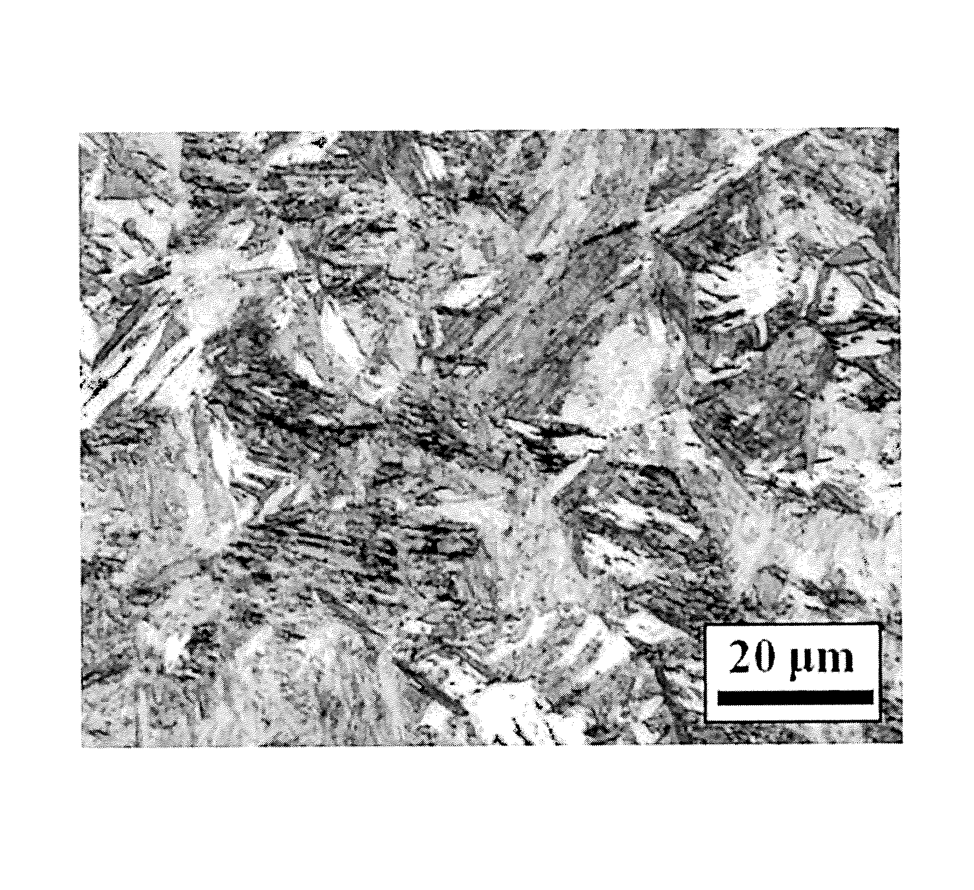
In a case in which the steel plate is cold rolled, a reduction ratio thereof may be 30% or more. As described above, in a case in which the steel plate is cold-rolled at a reduction ratio of 30% or more, as a ferrite structure is elongated in a rolling direction, a relatively large amount of residual transformation may be included inside thereof. In addition, as a pearlite structure is also elongated in a rolling direction, a fine carbide may be formed therein. The cold-rolled ferrite and pearlite structures may allow an austenite grain to be refined in a case in which subsequent heat treatments are undertaken, and may facilitate employment of a carbide. Thus, strength and ductility of the steel plate may be improved. Meanwhile, FIG. 1 is a view illustrating a microstructure, observed with an electron microscope, of a steel plate before heat treatment according to an exemplary embodiment in the present disclosure. It can be confirmed in FIG. 1 that ferrite and pearlite structures are elongated in a rolling direction, and a fine carbide is formed inside the pearlite structure.
Next, the cold-rolled steel plate is heated to a heating temperature (T*) of Ar3.degree. C. to Ar3+500.degree. C. For example, in a case in which the heating temperature (T*) is less than Ar3.degree. C., austenite may not be sufficiently formed. Thus, a martensite structure of 90 volume % or more may not be obtained after cooling the steel plate. On the other hand, in a case in which the heating temperature (T*) exceeds Ar3.degree. C.+500.degree. C., an austenite grain may be coarsened, and diffusion of carbon may be accelerated. Thus, two kinds of martensite having different levels of hardness may not be obtained after cooling the steel plate. Thus, the heating temperature may be Ar3.degree. C. to Ar3+500.degree. C., and in detail, be Ar3.degree. C. to Ar3+300.degree. C.
In a case in which heating the steel plate, a heating rate (v.sub.r, .degree. C./sec) may satisfy the following relational expression 2. If the v.sub.r does not satisfy relational expression 2, an austenite grain is coarsened during heating of the steel plate, and carbon is excessively diffused. Thus, two kinds of martensite having different hardness may not be obtained after cooling the steel plate. Meanwhile, as a heating rate is increased, an austenite grain is prevented from being coarsened and carbon is prevented from being diffused. Thus, an upper limit thereof is not particularly limited. v.sub.r.gtoreq.(T*/110).sup.2 [Relational Expression 2]
Meanwhile, according to an exemplary embodiment in the present disclosure, the cold-rolled and heated steel plate may have an austenite single phase structure having an average diameter of 20 .mu.m or less as a microstructure thereof. In a case in which an average diameter of the austenite single phase structure exceeds 20 .mu.m, there may be a risk of coarsening a packet size of a martensite structure formed after cooling the steel plate, and there may be a risk of decreasing strength and ductility of the steel plate by increasing a martensite transformation temperature.
Next, the heated steel plate is cooled. In this case, a cooling rate (v.sub.c, .degree. C./sec) may satisfy the following relational expression 3. If the v.sub.c does not satisfy relational expression 3, an austenite grain is coarsened during cooling of the steel plate, and carbon is excessively diffused. Thus, two kinds of martensite having different hardness may not be obtained after cooling the steel plate. In addition, a structure of the steel plate may be transformed into a ferrite, pearlite, or bainite structure during cooling of the steel plate. Thus, it may be difficult to secure a targeted martensite volume fraction. Meanwhile, as the cooling rate is increased, an austenite grain may be prevented from being coarsened and carbon may be prevented from being diffused. Thus, an upper limit thereof is not particularly limited. V.sub.c.gtoreq.(T*/80).sup.2 [Relational Expression 3]
Meanwhile, according to an exemplary embodiment in the present disclosure, in a case in which cooling the heated steel plate, a high-temperature retention time (t.sub.m, sec) may satisfy the following relational expression 4. The high-temperature retention time means the time required for initiating cooling of a steel plate having reached a heating temperature. In a case in which the high-temperature retention time satisfies relational expression 4, carbon may be prevented from being excessively diffused, and in addition, since an average diameter of an austenite grain before cooling is controlled to be 20 .mu.m or less, martensite having an average packet size of 20 .mu.m or less after cooling may be secured. Meanwhile, as the high-temperature retention time is further decreased, an austenite grain may be prevented from being coarsened and carbon from being diffused. Thus, a lower limit thereof is not particularly limited. t.sub.m.ltoreq.(8-0.006*T*).sup.2 [Relational Expression 4]
Hereinafter, the exemplary embodiments in the present disclosure will be described in more detail. The present disclosure may, however, be exemplified in many different forms and should not be construed as being limited to the specific embodiments set forth herein. While exemplary embodiments are shown and described, it will be apparent to those skilled in the art that modifications and variations could be made without departing from the scope of the present invention as defined by the appended claims below.
Embodiment
After steel plates having compositions illustrated in Table 1 is prepared, the steel plates were cold-rolled, heated, and cooled in a condition of Table 2. Then, a microstructure of the steel plate was observed, mechanical properties were measured, and the results therefrom are shown in Table 3. In this case, a tensile test was performed at a rate of 5 mm/min with respect to an ASTM subsized specimen, and a Vickers hardness test of each microstructure was performed at a condition in which the microstructure was maintained at a load of 5 g for 10 seconds.
TABLE-US-00001 TABLE 1 Steels C Mn Si P S Comparative 0.04 0.17 0.005 0.01 0.005 Steel 1 Inventive 0.10 1.49 0.003 0.02 0.003 Steel 1 Inventive 0.21 0.89 0.005 0.015 0.012 Steel 2
TABLE-US-00002 TABLE 2 Reduction Ratio T* v.sub.r v.sub.r* v.sub.c v.sub.c* t.sub.m t.sub.m* Steels (%) (.degree. C.) (.degree. C./sec) (.degree. C./sec) (.degree. C./sec) (.degree. C./sec) (sec) (sec) Note Comparative 70 1000 300 83 1000 156 1 4 Comparative Steel 1 Example 1 Comparative 70 900 300 67 1000 126 1 6.8 Comparative Steel 1 Example 2 Inventive 60 700 300 40 1000 76 1 14 Comparative Steel 1 Example 3 Inventive 60 900 300 67 1000 126 1 6.8 Inventive Steel 1 Example 1 Inventive 60 1000 300 82 1000 156 1 4 Inventive Steel 1 Example 2 Inventive 70 900 300 67 1000 126 1 6.8 Inventive Steel 2 Example 3 Inventive 70 1000 300 83 1000 156 1 4 Inventive Steel 2 Example 4 Inventive 70 1100 300 100 1000 189 1 2 Inventive Steel 2 Example 5 Inventive 70 1200 300 119 1000 225 0.1 0.6 Inventive Steel 2 Example 6 Inventive 70 1000 200 83 1000 156 1 4 Inventive Steel 2 Example 7 Inventive 70 1000 100 83 1000 156 1 4 Inventive Steel 2 Example 8 Inventive 70 1000 300 83 200 156 1 4 Inventive Steel 2 Example 9 Inventive 70 1000 300 83 1000 156 2 4 Inventive Steel 2 Example 10 Inventive 70 1000 50 83 1000 156 1 4 Comparative Steel 2 Example 4 Inventive 70 700 300 40 1000 76 1 14 Comparative Steel 2 Example 5 Inventive 70 1000 300 83 1000 156 5 4 Comparative Steel 2 Example 6 Inventive 70 1000 300 83 1000 156 20 4 Comparative Steel 2 Example 7 Inventive 70 1000 300 83 80 156 1 4 Comparative Steel 2 Example 8 Inventive 70 1200 300 119 1000 225 1 0.6 Comparative Steel 2 Example 9 Inventive 70 1300 300 140 1000 264 1 0.04 Comparative Steel 2 Example 10 v.sub.r* is a heating rate ((T*/110).sup.2) calculated by relational expression 2, v.sub.c* is a cooling rate ((T*/80).sup.2) calculated by relational expression 3, and t.sub.m* is a high-temperature retention time ((8 - 0.006 * T*).sup.2) calculated by relational expression 4.
TABLE-US-00003 TABLE 3 First Second relational Packet Tensile Micro- hardness hardness expression Size Strength Elongation Steels structure (HV) (HV) 1 (.mu.m) (MPa) (%) Note Comparative F + P -- -- -- -- 655 11.1 Comparative Steel 1 Example 1 Comparative F + P -- -- -- -- 661 17.8 Comparative Steel 1 Example 2 Inventive F + P -- -- -- -- 1014 11.9 Comparative Steel 1 Example 3 Inventive M1 + M2 454 372 28.1 8.9 1347 8.2 Inventive Steel 1 Example 1 Inventive M1 + M2 437 368 25.8 12.2 1311 9.7 Inventive Steel 1 Example 2 Inventive M1 + M2 662 513 22.5 6.8 1795 7.4 Inventive Steel 2 Example 3 Inventive M1 + M2 650 520 20 8.5 1775 8.1 Inventive Steel 2 Example 4 Inventive M1 + M2 627 510 23.7 13.7 1771 7.7 Inventive Steel 2 Example 5 Inventive M1 + M2 619 526 25.1 16.7 1702 8.1 Inventive Steel 2 Example 6 Inventive M1 + M2 634 513 19.1 11.8 1763 7.3 Inventive Steel 2 Example 7 Inventive M1 + M2 607 549 9.6 10.7 1742 7.1 Inventive Steel 2 Example 8 Inventive M1 + M2 614 545 11.2 9.1 1711 7.2 Inventive Steel 2 Example 9 Inventive M1 + M2 631 560 11.2 9.6 1759 7.2 Inventive Steel 2 Example 10 Inventive M1 + M2 567 540 4.7 15.5 1687 6.4 Comparative Steel 2 Example 4 Inventive F + P -- -- -- -- 1387 3.2 Comparative Steel 2 Example 5 Inventive M1 + M2 591 563 4.8 19.7 1712 5.9 Comparative Steel 2 Example 6 Inventive M1 + M2 578 553 4.3 27.7 1699 2.9 Comparative Steel 2 Example 7 Inventive F + P -- -- -- -- 649 20.1 Comparative Steel 2 Example 8 Inventive M1 + M2 570 543 22.1 4.7 1689 6.7 Comparative Steel 2 Example 9 Inventive M1 + M2 559 536 28.9 4.1 1684 6.4 Comparative Steel 2 Example 10 Here, F is ferrite, P is pearlite, M1 is martensite having a first hardness, and M2 is martensite having a second hardness
Inventive examples 1 to 10, satisfying a composition and a manufacturing method according to an exemplary embodiment in the present disclosure, include two kinds of martensite, a hardness difference of which is between 5% to 30%, thereby having tensile strength of 1200 MPa or more and elongation of 7% or more.
Meanwhile, comparative examples 1 and 2 include ferrite and pearlite as a microstructure after heat treatment as a carbon content in steel is relatively low, and strength thereof is inferior.
In addition, in comparative example 3, since a heating temperature (T*) is relatively low, ferrite and pearlite are included as a microstructure after heat treatment, and strength thereof is inferior. In comparative example 5, a heating temperature (T*) is relatively low, but a carbon content is relatively high. Thus, strength of steel is in a range controlled according to an exemplary embodiment in the present disclosure. However, a rolling structure by cold rolling is not sufficiently loosened, whereby ductility thereof is inferior.
In addition, in comparative examples 4, 6, 7, 9, and 10, one of v.sub.r and t.sub.m is outside of a range controlled according to an exemplary embodiment in the present disclosure. Thus, an austenite grain is coarsened, and carbon is diffused, whereby a martensite structure in which a difference of hardness is less than 5% is formed. In addition, steel strength is excellent, but ductility thereof is inferior.
In addition, in comparative example 8, v.sub.c is outside of a range controlled according to an exemplary embodiment in the present disclosure. Ferrite and pearlite structures are formed during cooling the steel plate, and ductility thereof is excellent but strength is inferior.
Meanwhile, FIG. 2 is a view illustrating a microstructure of a steel plate after heat treatment, observed with an optical microscope, according to inventive example 4 of the present disclosure. FIG. 3 is a view illustrating a microstructure of a steel plate after heat treatment, observed with an optical microscope, according to comparative example 5. Referring to FIG. 2, in a case of inventive example 4, a size of a martensite packet is finely formed to be 20 .mu.m or less. Thus, a plate inside the packet is also finely formed. Meanwhile, referring to FIG. 3 illustrating comparative example 5, a size of a martensite packet exceeds 20 .mu.m, and thus, martensite is formed to be coarse. In addition, a plate inside the packet is also formed to be coarse.
* * * * *
D00000
D00001
D00002
D00003
XML
uspto.report is an independent third-party trademark research tool that is not affiliated, endorsed, or sponsored by the United States Patent and Trademark Office (USPTO) or any other governmental organization. The information provided by uspto.report is based on publicly available data at the time of writing and is intended for informational purposes only.
While we strive to provide accurate and up-to-date information, we do not guarantee the accuracy, completeness, reliability, or suitability of the information displayed on this site. The use of this site is at your own risk. Any reliance you place on such information is therefore strictly at your own risk.
All official trademark data, including owner information, should be verified by visiting the official USPTO website at www.uspto.gov. This site is not intended to replace professional legal advice and should not be used as a substitute for consulting with a legal professional who is knowledgeable about trademark law.