Fractionalized stimulation pulses in an implantable stimulator device
Parramon , et al.
U.S. patent number 10,293,166 [Application Number 15/698,038] was granted by the patent office on 2019-05-21 for fractionalized stimulation pulses in an implantable stimulator device. This patent grant is currently assigned to Boston Scientific Neuromodulation Corporation. The grantee listed for this patent is Boston Scientific Neuromodulation Corporation. Invention is credited to Rafael Carbunaru, Matt I. Haller, Jordi Parramon.


View All Diagrams
| United States Patent | 10,293,166 |
| Parramon , et al. | May 21, 2019 |
Fractionalized stimulation pulses in an implantable stimulator device
Abstract
A method for configuring stimulation pulses in an implantable stimulator device having a plurality of electrodes is disclosed, which method is particularly useful in adjusting the electrodes by current steering during initialization of the device. In one aspect, a set of ideal pulses for patient therapy is determined, in which at least two of the ideal pulses are of the same polarity and are intended to be simultaneous applied to corresponding electrodes on the implantable stimulator device during an initial duration. These pulses are reconstructed into fractionalized pulses, each comprised of pulse portions. The fractionalized pulses are applied to the corresponding electrodes on the device during a final duration, but the pulse portions of the fractionalized pulses are not simultaneously applied during the final duration.
| Inventors: | Parramon; Jordi (Valencia, CA), Carbunaru; Rafael (Valley Village, CA), Haller; Matt I. (Valley Village, CA) | ||||||||||
|---|---|---|---|---|---|---|---|---|---|---|---|
| Applicant: |
|
||||||||||
| Assignee: | Boston Scientific Neuromodulation
Corporation (Valencia, CA) |
||||||||||
| Family ID: | 40636900 | ||||||||||
| Appl. No.: | 15/698,038 | ||||||||||
| Filed: | September 7, 2017 |
Prior Publication Data
| Document Identifier | Publication Date | |
|---|---|---|
| US 20170368355 A1 | Dec 28, 2017 | |
Related U.S. Patent Documents
| Application Number | Filing Date | Patent Number | Issue Date | ||
|---|---|---|---|---|---|
| 15210726 | Jul 14, 2016 | 9782593 | |||
| 14329608 | Jul 19, 2016 | 9393423 | |||
| 12824663 | Aug 19, 2014 | 8812131 | |||
| 12121281 | Feb 15, 2011 | 7890182 | |||
| Current U.S. Class: | 1/1 |
| Current CPC Class: | A61N 1/37235 (20130101); A61N 1/36178 (20130101); A61N 1/36071 (20130101); A61N 1/05 (20130101); A61N 1/36171 (20130101); A61N 1/36125 (20130101); A61N 1/36175 (20130101); A61N 1/0551 (20130101) |
| Current International Class: | A61N 1/36 (20060101); A61N 1/372 (20060101); A61N 1/05 (20060101) |
References Cited [Referenced By]
U.S. Patent Documents
| 3646940 | March 1972 | Timm et al. |
| 3727616 | April 1973 | Lenzkes |
| 3822708 | July 1974 | Zilber |
| 4177819 | December 1979 | Kofsky et al. |
| 4408608 | October 1983 | Daly et al. |
| 4520825 | June 1985 | Thompson et al. |
| 4535777 | August 1985 | Castel |
| 4608985 | September 1986 | Crish et al. |
| 4649936 | March 1987 | Ungar et al. |
| 4702254 | October 1987 | Zabara |
| 5007902 | April 1991 | Witt |
| 5095904 | March 1992 | Seligman et al. |
| 5119832 | June 1992 | Xavier |
| 5188104 | February 1993 | Wernicke et al. |
| 5199430 | April 1993 | Fang et al. |
| 5271397 | December 1993 | Seligman et al. |
| 5562717 | October 1996 | Tippey et al. |
| 5601617 | February 1997 | Loeb et al. |
| 5700282 | December 1997 | Zabara |
| 5776170 | July 1998 | MacDonald et al. |
| 5983141 | November 1999 | Sluijter et al. |
| 6002964 | December 1999 | Feler et al. |
| 6052624 | April 2000 | Mann |
| 6161048 | December 2000 | Sluijter et al. |
| 6178351 | January 2001 | Mower |
| 6185425 | February 2001 | Schulman et al. |
| 6246912 | June 2001 | Sluijter et al. |
| 6298256 | October 2001 | Meyer |
| 6325764 | December 2001 | Griffith et al. |
| 6393325 | May 2002 | Mann et al. |
| 6516227 | February 2003 | Meadows et al. |
| 6587724 | July 2003 | Mann |
| 6600954 | July 2003 | Cohen et al. |
| 6609032 | August 2003 | Woods et al. |
| 6615084 | September 2003 | Cigaina |
| 6684105 | January 2004 | Cohen et al. |
| 6712753 | March 2004 | Manne |
| 6731986 | May 2004 | Mann |
| 6775148 | August 2004 | Hong |
| 6839594 | January 2005 | Cohen et al. |
| 6849073 | February 2005 | Hoey et al. |
| 6895280 | May 2005 | Meadows et al. |
| 6907130 | June 2005 | Rubinstein et al. |
| 6909917 | June 2005 | Woods et al. |
| 6928320 | August 2005 | King |
| 6978180 | December 2005 | Tadlock |
| 7054686 | May 2006 | MacDonald |
| 7054689 | May 2006 | Whitehurst et al. |
| 7146223 | December 2006 | King |
| 7174215 | February 2007 | Bradley |
| 7177690 | February 2007 | Woods et al. |
| 7180760 | February 2007 | Varrichio et al. |
| 7184837 | February 2007 | Goetz |
| 7203548 | April 2007 | Whitehurst et al. |
| 7212133 | May 2007 | Goetze et al. |
| 7212865 | May 2007 | Cory |
| 7239926 | July 2007 | Goetz |
| 7247155 | July 2007 | Hoey et al. |
| 7252090 | August 2007 | Goetz |
| 7263402 | August 2007 | Thacker et al. |
| 7292890 | November 2007 | Whitehurst et al. |
| 7317945 | January 2008 | Litvak et al. |
| 7389145 | June 2008 | Kilgore et al. |
| 7450987 | November 2008 | Varrichio et al. |
| 7496404 | February 2009 | Meadows et al. |
| 7519431 | April 2009 | Goetz et al. |
| 7526341 | April 2009 | Goetz et al. |
| 7571007 | August 2009 | Erickson |
| 7603174 | October 2009 | De Ridder |
| 7613519 | November 2009 | De Ridder |
| 7613520 | November 2009 | De Ridder |
| 7676273 | March 2010 | Goetz et al. |
| 7734340 | June 2010 | De Ridder |
| 7742819 | June 2010 | Moffitt |
| 7769462 | August 2010 | Meadows |
| 7805197 | September 2010 | Bradley |
| 7860570 | December 2010 | Whitehurst et al. |
| 7890182 | February 2011 | Parramon et al. |
| 7890185 | February 2011 | Cohen et al. |
| 8027718 | September 2011 | Spinner et al. |
| 8060208 | November 2011 | Kilgore et al. |
| 8224453 | June 2012 | De Ridder |
| 8280515 | October 2012 | Greenspan |
| 8340775 | December 2012 | Cullen et al. |
| 8364271 | January 2013 | De Ridder |
| 8364273 | January 2013 | DeRidder |
| 8401655 | March 2013 | DeRidder |
| 8423147 | April 2013 | Alataris et al. |
| 8428748 | April 2013 | Alataris et al. |
| 8433418 | April 2013 | De Ridder |
| 8612018 | December 2013 | Gillbe |
| 8712533 | April 2014 | Alataris et al. |
| 8788044 | July 2014 | John |
| 8825166 | September 2014 | John |
| 8977363 | March 2015 | Carroll et al. |
| 9393423 | July 2016 | Parramon et al. |
| 2002/0055779 | May 2002 | Andrews |
| 2002/0091423 | July 2002 | Rubinstein |
| 2004/0015205 | January 2004 | Whitehurst et al. |
| 2004/0049231 | March 2004 | Hafer |
| 2004/0158304 | August 2004 | Cory et al. |
| 2004/0167583 | August 2004 | Knudson et al. |
| 2004/0167584 | August 2004 | Carroll et al. |
| 2004/0172085 | September 2004 | Knudson et al. |
| 2004/0172086 | September 2004 | Knudson et al. |
| 2004/0172088 | September 2004 | Knudson et al. |
| 2004/0176812 | September 2004 | Knudson et al. |
| 2004/0193230 | September 2004 | Overstreet et al. |
| 2004/0210270 | October 2004 | Erickson |
| 2004/0210271 | October 2004 | Campen et al. |
| 2005/0038484 | February 2005 | Knudson et al. |
| 2005/0065575 | March 2005 | Dobak |
| 2005/0143781 | June 2005 | Carbunaru et al. |
| 2005/0149148 | July 2005 | King |
| 2005/0203588 | September 2005 | King |
| 2005/0209655 | September 2005 | Bradley et al. |
| 2005/0245977 | November 2005 | Varrichio et al. |
| 2005/0245987 | November 2005 | Woods et al. |
| 2005/0245993 | November 2005 | Varrichio et al. |
| 2005/0245994 | November 2005 | Varrichio et al. |
| 2006/0004422 | January 2006 | De Ridder |
| 2006/0009820 | January 2006 | Royle |
| 2006/0015153 | January 2006 | Gliner et al. |
| 2006/0025832 | February 2006 | O'Keefe et al. |
| 2006/0030895 | February 2006 | Simon et al. |
| 2006/0030899 | February 2006 | O'Keefe et al. |
| 2006/0074456 | April 2006 | Pyles et al. |
| 2006/0161236 | July 2006 | King |
| 2006/0170486 | August 2006 | Tranchina et al. |
| 2006/0195145 | August 2006 | Lee et al. |
| 2006/0229687 | October 2006 | Goetz et al. |
| 2006/0259098 | November 2006 | Erickson et al. |
| 2007/0060954 | March 2007 | Cameron et al. |
| 2007/0073354 | March 2007 | Knudson et al. |
| 2007/0097719 | May 2007 | Parramon et al. |
| 2007/0123953 | May 2007 | Lee et al. |
| 2007/0150034 | June 2007 | Rooney et al. |
| 2007/0156203 | July 2007 | Varrichio et al. |
| 2007/0203538 | August 2007 | Stone et al. |
| 2007/0203540 | August 2007 | Goetz et al. |
| 2007/0203543 | August 2007 | Stone et al. |
| 2007/0203546 | August 2007 | Stone et al. |
| 2007/0213789 | September 2007 | Nolan et al. |
| 2007/0213790 | September 2007 | Nolan et al. |
| 2007/0239226 | October 2007 | Overstreet |
| 2007/0239228 | October 2007 | Bradley |
| 2007/0244519 | October 2007 | Keacher et al. |
| 2007/0245318 | October 2007 | Goetz et al. |
| 2007/0265679 | November 2007 | Bradley et al. |
| 2007/0276450 | November 2007 | Meadows et al. |
| 2007/0293914 | December 2007 | Woods et al. |
| 2007/0299482 | December 2007 | Littlewood et al. |
| 2008/0004674 | January 2008 | King et al. |
| 2008/0027514 | January 2008 | DeMulling et al. |
| 2008/0033511 | February 2008 | Dobak |
| 2008/0046036 | February 2008 | King et al. |
| 2008/0058773 | March 2008 | John |
| 2008/0071325 | March 2008 | Bradley |
| 2008/0103552 | May 2008 | Goetz et al. |
| 2008/0215119 | September 2008 | Woods et al. |
| 2008/0221637 | September 2008 | Woods et al. |
| 2008/0228236 | September 2008 | Varrichio et al. |
| 2008/0234791 | September 2008 | Arle et al. |
| 2008/0288023 | November 2008 | John |
| 2009/0024189 | January 2009 | Lee et al. |
| 2009/0048643 | February 2009 | Erickson et al. |
| 2009/0204173 | August 2009 | Fang et al. |
| 2010/0137938 | June 2010 | Kishawi et al. |
| 2010/0152817 | June 2010 | Gillbe |
| 2010/0241190 | September 2010 | Kilgore et al. |
| 2010/0249875 | September 2010 | Kishawi et al. |
| 2011/0009919 | January 2011 | Carbunaru et al. |
| 2011/0184488 | July 2011 | De Ridder |
| 2012/0172946 | June 2012 | Alataris et al. |
| 101239222 | Aug 2008 | CN | |||
| 2449546 | Nov 2008 | GB | |||
| S58-086177 | May 1983 | JP | |||
| 2001/043818 | Jun 2001 | WO | |||
| 2003/066154 | Aug 2003 | WO | |||
| 2004/007018 | Jan 2004 | WO | |||
| 2004/043537 | May 2004 | WO | |||
| 2005/099813 | Oct 2005 | WO | |||
| 2005/101627 | Oct 2005 | WO | |||
| 2005/101660 | Oct 2005 | WO | |||
| 2005/101661 | Oct 2005 | WO | |||
| 2006/073393 | Jul 2006 | WO | |||
| 2006/073405 | Jul 2006 | WO | |||
| 2006/112852 | Oct 2006 | WO | |||
| 2006/128037 | Nov 2006 | WO | |||
| 2007/002741 | Jan 2007 | WO | |||
| 2008/142402 | Nov 2008 | WO | |||
| 2009/061813 | May 2009 | WO | |||
| 2010/111358 | Sep 2010 | WO | |||
Other References
|
"Analysis of Failed Spinal Cord Stimulation Trials in the Treatment of Intractable Chronic Pain," J. Korean Neurosurgery Society, vol. 43, 2008, pp. 85-89. cited by applicant . Banazzour et al.; Reversal of Rigidity and Improvement in Motor Performance by Subthalamic High-frequency Stimulation in MPTP-treated Monkeys; (1992), European Journal of Neuroscience, vol. 5, pp. 382-389. cited by applicant . Barolat, Giancarlo, et al., "Multifactorial Analysis of Epidural Spinal Cord Stimulation," Stereotactic and Functional Neurosurgery, 56, 1991, pp. 77-103. cited by applicant . Beurrier et al., Subthalamic Stimulation Elicits Hemiballismus in Normal Monkey, NeuroReport, vol. 8, No. 7, May 6, 1997, pp. 1625-1629. cited by applicant . Beurrier et al., Subthalamic Nucleus Neurons Switch from Single-Spike Activity to Burst-Firing Mode; The Journal of Neuroscience, Jan. 15, 1999, 19(2):599-609. cited by applicant . Bhadra, Narendra, et al., "High Frequency Electrical Conduction Block of the Pudendal Nerve," Journal of Neural Engineering, Institute of Physics Publishing, vol. 3, May 17, 2006, pp. 180-187. cited by applicant . Bhadra, Niloy, et al., "High-Frequency Electrical Conduction Block of Mammalian Peripheral Motor Nerve," Muscle & Nerve, 32, Dec. 2005, pp. 782-790. cited by applicant . Bhadra, Niloy, et al., "Simulation of High-Frequency Sinusoidal Electrical Block of Mammalian Myelinated Axons," Springer, J Comput Neurosci, Jan. 3, 2007, 22, pp. 313-326. cited by applicant . Boger, Adam, et al., "Bladder Voiding by Combined High Frequency Electrical Pudendal Nerve Block and Sacral Root Stimulation," Wiley Interscience, Neurourology and Urodynamics, 27, 2008, pp. 435-439. cited by applicant . Bowman, Bruce R., et al., "Response of Single Alpha Motoneurons to High-Frequency Pulse Trains," Appl. Neurophysial., 49, 1986, pp. 121-138. cited by applicant . Cahana, Alex, et al., "Acute Differential Modulation of Synaptic Transmission and Cell Survival During Exposure to Pulsed and Continuous Radiofrequency Energy," The Journal of Pain, vol. 4, No. 4, May 2003, pp. 197-202. cited by applicant . De Ridder, Dirk, et al., "Are Paresthesias Necessary for Pain Suppression in SCS? Burst Stimulation," Brain Research Center Antwerp for Innovative and Interdisciplinary Neuromodulation, 2010, 28 pages. cited by applicant . De Ridder, Dirk, et al., "Burst Spinal Cord Stimulation: Toward Paresthesia-Free Pain Suppression," Neurosurgery Online, vol. 66, No. 5, May 2010, pp. 986-990, obtained from <www.neurosurgery-online.com>. cited by applicant . Geddes, Leslie A., Accuracy Limitations of Chronaxie Values, IEEE Transactions on Biomedical Engineering, vol. 51, No. 1, Jan. 2004, pp. 176-181. cited by applicant . Grill, Warren M., et al., "Stimulus Waveforms for Selective Neural Stimulation," IEEE Engineering in Medicine and Biology, Jul./Aug. 1995, pp. 375-385. cited by applicant . Higuchi, Yoshinori, M.D., et al., "Exposure of the Dorsal Root Ganglion in Rats to Pulsed Radiofrequency Currents Activates Dorsal Horn Lamina I and II Neurons," Neurosurgery, vol. 50, No. 4, Apr. 2002, pp. 850-856. cited by applicant . Holsheimer, Jan, et al., "Effectiveness of Spinal Cord Stimulation in the Management of Chronic Pain: Analysis of Technical Drawbacks and Solutions," Neurosurgery, vol. 40, Issue 5, May 1997, Apr. 23, 2009, pp. 990-999, obtained from <http://journals.lww.com/neurosurgery/Fulltext/1997/05000/Effectivenes- s_of_Spinal_Cord_Stimulation_in_the.23.aspx>. cited by applicant . Hopp, F.A., et al., "Effect of Anodal Blockade of Myelinated Fibers on Vagal C-Fiber Afferents," The American Physiological Society, Apr. 21, 1980, pp. 454-462. cited by applicant . Huxley, A. F., "Excitation and Conduction in Nerve: Quantitative Analysis," Science, vol. 145, Sep. 11, 1964, pp. 1154-1159. cited by applicant . Kilgore et al., Nerve Conduction Block Utilising High-frequency Alternating Current, Medical & Biological Engineering & Computing, 2004, vol. 42, pp. 394-406. cited by applicant . Kilgore, Kevin L., Ph.D., et al., "Reversible Nerve Conduction Block Using Kilohertz Frequency Alternating Current," Neuromodulation: Technology at the Neural Interface, International Neurmodulation Society, 17, 2014, pp. 242-255. cited by applicant . Kumar, Krishna, M.B.B.S., M.S., et al., "Spinal Cord Stimulation in Treatment of Chronic Benign Pain: Challengs in Treatment Planning and Present Status, a 22-Year Experience," Neurosurgery, vol. 58, No. 3, Mar. 2006, pp. 481-496. cited by applicant . Larson, Sanford J., M.D., Ph.D., et al., "Neurophysiological Effects of Dorsal Column Stimulation in Man and Monkey," Journal of Neurosurgery, vol. 41, Aug. 1974, pp. 217-223. cited by applicant . Linderoth, Bengt, M.D., Ph.D., et al., "Mechanisms of Spinal Cord Stimulation in Painful Syndromes: Role of Animal Models," American Academy of Pain Medicine, vol. 7, No. S1, 2006, pp. S14-S26. cited by applicant . Linderoth, Bengt, M.D., Ph.D., et al., "Physiology of Spinal Cord Stimulation: Review and Update," International Neuromodulation Society, Neuromodulation, vol. 2, No. 3, 1999, pp. 150-164. cited by applicant . Macdonald, Alexander J.R., et al., "The Discovery of Transcutaneous Spinal Electroanalgesia and its Relief of Chronic Pain," Physiotherapy, vol. 81, No. 11, Nov. 1995, pp. 653-661. cited by applicant . Mateev et al.; "Implications of All-or-None Synaptic Transmission and Short-Term Depression beyond Vesicle Depletion: a Computational Study;" The Journal of Neuroscience. Feb. 15, 2000; pp. 1575-1588. cited by applicant . Mateev et al.; "Differential Short-term Synaptic Plasticity and Transmission of Complex Spike Trains to Depress or to Facilitate;" Cerebral Cortex; Nov. 2000; vol. 10 No. 11; pp. 1143-1153. cited by applicant . Mediati, R.D., Powerpoint entitled "Mechanisms of Spinal Cord Stimulation," Florence, Oct. 2, 2002, 31 pages. cited by applicant . Melzack, Ronald, et al., "Pain Mechanisms: A New Theory," Science, vol. 150, No. 3699, Nov. 19, 1965, pp. 971-979. cited by applicant . Miles, J D, et al., "Effects of Ramped Amplitude Waveforms on the Onset Response of High-Frequency Mammalian Nerve Block," Journal of Neural Engineenring, IOP Publishing, 4, 2007, pp. 390-398. cited by applicant . Muller, A., et al., "Reversible Blockierung der Erregungsleitung im Nerven Dureh Mittelfreimenz-Dauerstrom," Helvetica Physiologica et Pharmacologica Acta, Schwabe & Co., Basel, vol. 25, 1, 1967, pp. 211-213. cited by applicant . Munglani, Rajesh, "The Longer Term Effect of Pulsed Radiofrequency for Neuropathic Pain," International Association for the Study of Pain, pp. 437-439, 1999. cited by applicant . Nashold, Blaine S., Jr., M.D., et al., "Dorsal Column Stimulation for Control of Pain," Journal of Neurosurgery, vol. 36, May 1972, pp. 590-597. cited by applicant . North, Richard B., M.D., et al., "Failed Back Surgery Syndrome: 5-Year Follow-Up After Spinal Cord Stimulator Implantation," Neurosurgery Official Journal of the Congress of Neurological Surgeons, Williams & Wilkins, vol. 28, No. 5, May 1991, pp. 692-699. cited by applicant . North, Richard B., M.D., et al., "Spinal Cord Stimulation for Axial Low Back Pain--A Prospective, Controlled Trial Comparing Dual with Single Percutaneous Electrodes," Spine, Williams and Wilkins, Inc., vol. 30, No. 12, 2003, pp. 1412-1418. cited by applicant . North, Richard B., M.D., et al., "Spinal Cord Stimulation for Chronic, Intratable Pain: Experience Over Two Decades," Neurosurgery, vol. 32, No. 3, Mar. 1993, pp. 384-395. cited by applicant . North, Richard B., M.D., et al., "Spinal Cord Stimulation With Interleaved Pulses: A Randomized, Controlled Trial," Neuromodulation: Technology at the Neural Interface, vol. 10, No. 4, 2007, pp. 349-357. cited by applicant . Nunemaker et al., A Tale of Two Rhythms: A Comparative Review of the Pulsatile Endocrine Systems Regulating insulin and GnRH Secretion, Department of Pharmacology and Toxicology, Virginia Commonwealth University, P. O. Box 980524, Richmond, VA 23298, Received Jul. 24 .COPYRGT. Cellscience 2005. cited by applicant . Oakley, John C., M.D., et al., "Spinal Cord Stimulation--Mechanisms of Action," Spine, Williams & Wilkins, Inc., vol. 27, No. 22, 2002, pp. 2574-2583. cited by applicant . Perruchoud, Christophe, M.D., et al., "Analgesic Efficacy of High-Frequency Spinal Cord Stimulation: A Randomized Double-Blind Placebo-Controlled Study," International Neuromodulation Society, Neuromodulation: Technology at the Neural Interface, vol. 16, 2013, pp. 363-369. cited by applicant . U.S. Appl. No. 60/895,061, filed Mar. 15, 2007 titled "Spinal Cord Stimulation to Treat Pain." cited by applicant . "Reversible Blocking of Nerve Conduction by Alternating--Current Excitation," Nature, vol. 185, No. 4842, Aug. 18, 1962, pp. 712-713. cited by applicant . Shealy, C. Norman, M.D., et al., "Electrical Inhibition of Pain by Stimulation of the Dorsal Columns: Preliminary Clinical Report," Anesthesia and Analgesia . . . Current Researches, vol. 46, No. 4, Jul.-Aug. 1967, pp. 489-491. cited by applicant . Shelden, C. Hunter, M.D., et al., "Development and Clinical Capabilities of a New Implantable Biostimulator," The American Journal of Surgery, vol. 124, Aug. 1972, pp. 212-217. cited by applicant . Simpson, B.A., "Spinal Cord Stimulation in 60 Cases of Intractable Pain," Journal of Neurology, Neurosurgery, and Psychiatry, 54, 1991, pp. 196-199. cited by applicant . Simpson, B.A., "Spinal Cord Stimulation," British Journal of Neurosurgery, vol. 11, No. 1, 1997, pp. 5-11. cited by applicant . Sluijter, Menno E. et al., "The Effects of Pulsed Radiofrequency Fields Applied to the Dorsal Root Ganglion--A Preliminary Report," The Pain Clinic, vol. 11, No. 2, pp. 109-117, 1998. cited by applicant . Smith, Joseph R., et al., "Alleviation of Deafferentation Pain by Posterior Spinal Cord Stimulation Without Development of Paresthesias in the Area of Pain," The Clinical Journal of Pain, 4:157-160, 1988, Raven Press, Ltd., New York, pp. 157-160. cited by applicant . Solomonow, M., Ph.D., et al., "Control of Muscle Contractile Force Through Indirect High-Frequency Stimulation," The Williams & Wilkins Co., American Journal of Physical Medicine, vol. 62, No. 2, 1983, pp. 71-82. cited by applicant . Sweet, William H., M.D., D.Sc., et al., "Stimulation of the Posterior Columns of the Spinal Cord for Pain Control: Indications, Technique, and Results," The Congress of Neurological Surgeons, Clinical Neurosurgery, Honolulu, Hawaii, 1973, Chapter 24, pp. 278-310. cited by applicant . Towell, A.D., et al., "High Frequency Non-Invasive Stimulation Over the Spine: Effects on Mood and Mechanical Pain Tolerance in Normal Subjects," Rapid Science Publishers, Behavioural Neurology, vol. 10, 1997, pp. 61-65. cited by applicant . Urbain et al., The Switch of Subthalamic Neurons From an Irregular to a Bursting Pattern Does Not Soley Depend on Their GABAergic Inputs in the Anesthetic-Free Rat, The Journal of Neuroscience, Oct. 1, 2002, 22(19): pp. 8665-8675. cited by applicant . Urban, Bruno J., M.D., et al., "Percutaneous Epidural Stimulation of the Spinal Cord for Relief of Pain," Journal of Neurosurgery, vol. 48, No. 3, Mar. 1978, pp. 323-328. cited by applicant . Van Den Honert, Christopher, et al., "A Technique for Collision Block of Peripheral Nerve: Frequency Dependence," IEEE Transactions on Biomedical Engineering, vol. BME-28, No. 5, May 1981, pp. 379-382. cited by applicant . Van Den Honert, Christopher, et al., "Generation of Unidirectionally Propagated Action Potentials in a Periphreral Nerve by Brief Stimuli," Science, vol. 206, Dec. 14, 1979, pp. 1311-1312. cited by applicant . Woo, Moon Yo, et al., "Asynchronous Firing and Block of Peripheral Nerve Conduction by 20 Kc Alternating Current," Department of Neurosurgery, Loma Linds University School of Medicine and Los Angeles Hospital, .pdf created on Nov. 12, 2014, obtained Nov. 23, 2015, pp. 87-94. cited by applicant . Zhang, Xa, et al., "Simulation Analysis of Conduction Block in Myelinated Axons Induced by High-Frequency Biphasic Rectangular Pulses," IEEE Transactions on Biomedical Engineering, vol. 53, No. 7, Jul. 2006, pp. 1433-1436. cited by applicant. |
Primary Examiner: Schaetzle; Kennedy
Attorney, Agent or Firm: Lewis & Reese, PLLC
Parent Case Text
CROSS-REFERENCE TO RELATED APPLICATIONS
This is a continuation of U.S. patent application Ser. No. 15/210,726, filed Jul. 14, 2016 (now U.S. Pat. No. 9,782,593), which is a continuation of U.S. patent application Ser. No. 14/329,608, filed Jul. 11, 2014 (now U.S. Pat. No. 9,393,423), which is a continuation of U.S. patent application Ser. No. 12/824,663, filed Jun. 28, 2010 (now U.S. Pat. No. 8,812,131), which is a continuation of U.S. patent application Ser. No. 12/121,281, filed May 15, 2008 (now U.S. Pat. No. 7,890,182). These applications are incorporated herein by reference in their entireties and priority is claimed to them.
Claims
What is claimed is:
1. An implantable medical device, comprising: source circuitry configured to convert first stimulation parameters into a current that is sourced to a first electrode; sink circuitry configured to convert second stimulation parameters into a current that is sunk from a second electrode; and control logic configured to provide the first stimulation parameters to one of the source or sink circuitry, and to provide the second stimulation parameters to the other of the source or sink circuitry, wherein the first stimulation parameters define a first group of a plurality of first pulses that occurs during a duration, wherein the plurality of first pulses have a first frequency of greater than or equal to 2,000 Hz within the first group, and wherein the second stimulation parameters define a constant current during the duration.
2. The implantable medical device of claim 1, wherein the control logic is configured to provide a second frequency, wherein the first stimulation parameters thereby define during successive durations a plurality of first groups of the plurality of first pulses at the second frequency, and wherein the second stimulation parameters thereby define during the successive durations second pulses of the constant current at the second frequency.
3. The implantable medical device of claim 2, wherein, at times between the successive durations, no current is sourced or sunk from the source or sink circuitry.
4. The implantable medical device of claim 1, further comprising a receiver configured to wirelessly receive the first and second stimulation parameters from a device external to the implantable medical device.
5. The implantable medical device of claim 1, the first stimulation parameters define times in the first group between consecutive ones of the first pulses during which no current is sourced or sunk.
6. The implantable medical device of claim 1, wherein the control logic is configured to provide the first and second stimulation parameters within a single timing channel.
7. The implantable medical device of claim 1, wherein the first frequency is less than or equal to 10,000 Hz.
8. The implantable medical device of claim 1, wherein the source circuitry and the sink circuitry comprise constant current circuitry.
9. The implantable medical device of claim 1, further comprising first and second leads coupled to the implantable medical device, wherein the first and second electrodes are carried on one of the first and second leads, or wherein the first electrode is carried on the first lead and the second electrode is carried on the second lead.
10. The implantable medical device of claim 9, wherein the first and second leads are configured to be implanted on either side of a physiological midline of a patient's spinal cord.
11. The implantable medical device of claim 9, wherein the first and second leads are configured to be positioned within an epidural space of a patient's spinal cord.
12. The implantable medical device of claim 1, wherein the current that is sourced to the first electrode during the duration and the current that is sunk from the second electrode during the duration are equivalent in electrical charge.
13. The implantable medical device of claim 1, wherein the source or sink circuitry is further configured to convert third stimulation parameters into a current that is respectively sourced to or sunk from a third electrode.
14. The implantable medical device of claim 13, wherein the third stimulation parameters define a second group of a plurality of second pulses that occur during the duration.
15. The implantable medical device of claim 14, wherein the control logic is configured to provide the third stimulation parameters to the one of the source or sink circuitry to which the first stimulation parameters are provided, and wherein the second plurality of pulses are interleaved with the first plurality of pulses during the duration.
16. A method, comprising: providing, with control circuitry in an implantable medical device, first stimulation parameters to one of source or sink circuitry in the implantable medical device and second stimulation parameters to the other of the source or sink circuitry, wherein the first stimulation parameters define a first group of a plurality of first pulses that occurs during a duration, wherein the plurality of first pulses have a first frequency of greater than or equal to 2,000 Hz within the first group, and wherein the second stimulation parameters define a constant current during the duration; converting, with the source or sink circuitry, the first stimulation parameters into a current that is sourced to or sunk from a first electrode during the duration; and converting, with the other of the source or sink circuitry, the second stimulation parameters into the constant current that is the other of is sourced to or sunk from a second electrode during the duration.
17. The method of claim 16, wherein the first stimulation parameters define during successive durations a plurality of first groups of the plurality of first pulses at a second frequency, and wherein the second stimulation parameters define during the successive durations second pulses of the constant current at the second frequency.
18. The method of claim 17, wherein, at times between the successive durations, no current is sourced or sunk from the source or sink circuitry.
Description
FIELD OF THE INVENTION
The present invention relates to therapeutic electrical stimulation systems and methods and, more specifically, relates to adjusting electrodes of an implantable stimulator device.
BACKGROUND
Implantable stimulation devices are devices that generate and deliver electrical stimuli to body nerves and tissues for the therapy of various biological disorders, such as pacemakers to treat cardiac arrhythmia, defibrillators to treat cardiac fibrillation, cochlear stimulators to treat deafness, retinal stimulators to treat blindness, muscle stimulators to produce coordinated limb movement, spinal cord stimulators to treat chronic pain, cortical and deep brain stimulators to treat motor and psychological disorders, and other neural stimulators to treat urinary incontinence, sleep apnea, shoulder sublaxation, etc. The present invention may find applicability in all such applications, although the description that follows will generally focus on the use of the invention within a spinal cord stimulation system, such as that disclosed in U.S. Pat. No. 6,516,227, which is incorporated herein by reference in its entirety.
Spinal cord stimulation is a well-accepted clinical method for reducing pain in certain populations of patients. As shown in FIGS. 1A, 1B, 2A, and 2B, a Spinal Cord Stimulation (SCS) system typically includes an Implantable Pulse Generator (IPG) or Radio-Frequency (RF) transmitter and receiver 100 (collectively, "IPGs"), at least one electrode lead 102 and/or 104 having a plurality of electrodes 106, and, optionally, at least one electrode lead extension 120. The electrodes 106 are arranged in a desired pattern and spacing on the lead(s) 102, 104 to create an electrode array 110. Wires 112, 114 within one or more leads(s) 102, 104 connect each electrode 106 in the array 110 with appropriate current source/sink circuitry in the IPG 100.
In an SCS application, the electrodes lead(s) 102, 104 with the electrodes 106 are typically implanted along the spinal cord 19 (FIG. 2B), and the IPG 100 generates electrical pulses that are delivered through the electrodes 106 to the nerve fibers within the spinal column. The IPG 100 body itself is normally implanted in a subcutaneous pocket, for example, in the patient's buttocks or abdomen. The electrode lead(s) 102, 104 exit the spinal column and generally attach to one or more electrode lead extensions 120 (FIG. 2), which in turn are typically tunneled around the torso of the patient to the subcutaneous pocket where the IPG 100 is implanted. Alternatively, if the distance between the lead(s) 102, 104 and the IPG 100 is short, the electrode lead(s) 102, 104 may directly connect with the IPG 100 without lead extensions 120. For examples of other SCS systems and other stimulation system, see U.S. Pat. Nos. 3,646,940 and 3,822,708, which are hereby incorporated by reference in their entireties. Of course, an IPG 100 is an active device requiring energy for operation, which may be provided by an implanted battery or an external power source.
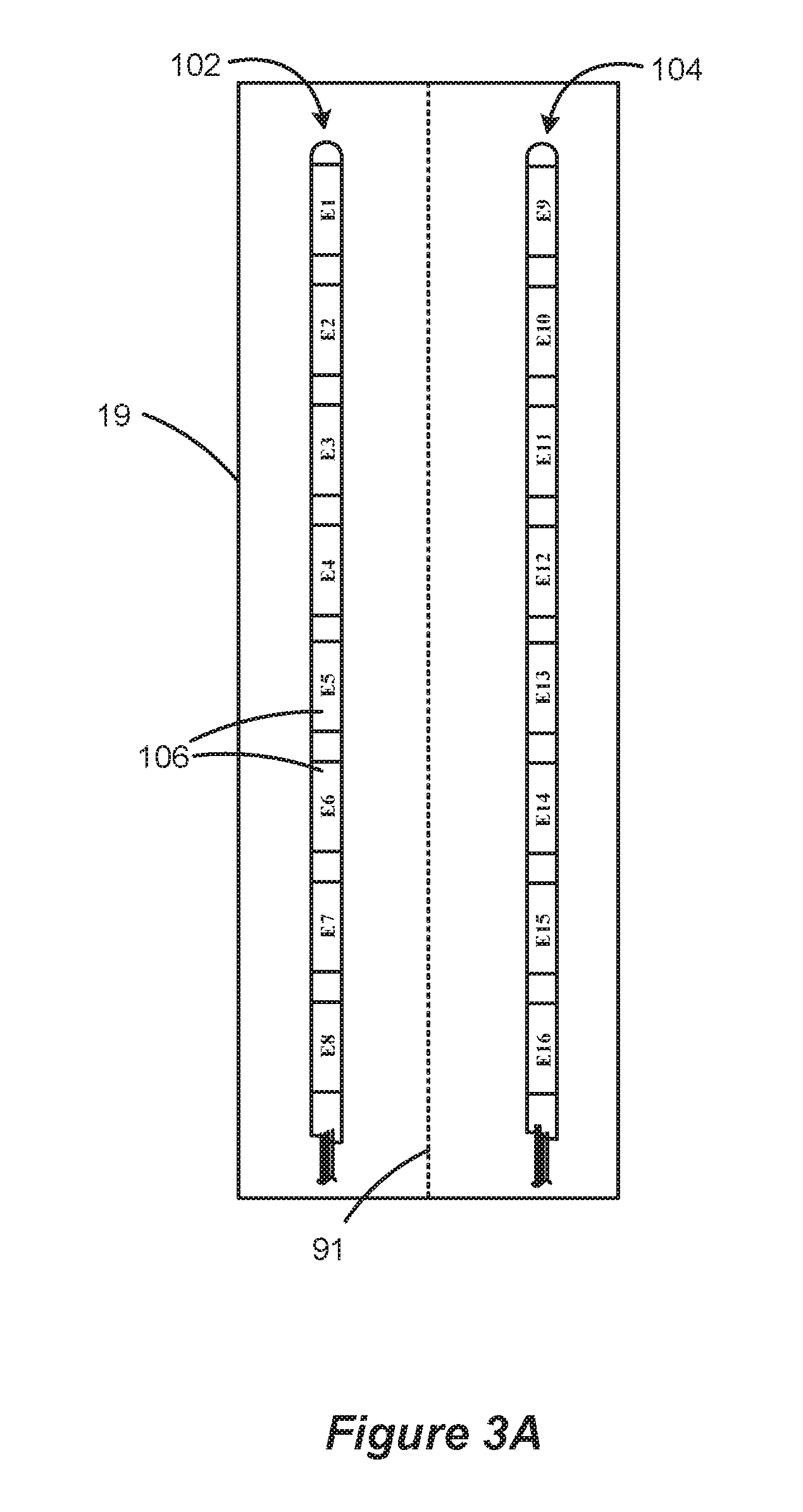
Precise placement of the lead(s) 102, 104 relative to the target nerves is important for achieving a satisfactory physiological response, and for keeping stimulation thresholds low to conserve battery power. A conventional lead implantation procedure commonly places the leads 102, 104 parallel to the spinal cord column 19 at or near the physiological midline 91, as is shown in FIGS. 3A and 3B. More particularly, and as best shown in the cross section of FIG. 3B, the electrode leads 102, 104 are placed directly on the dura mater 51 within the epidural space 70. (Cerebro-spinal fluid 72 is between the electrode array 110 and the white matter 52 of the spinal cord 19. Dorsal root nerves 50 are shown emanating from grey matter 53). When the leads 102, 104 are placed on opposite sides of the physiological midline 91 as shown, additional flexibility is provided in the ability to recruit (i.e., stimulate) nerves in the dorsal column, and to treat symptoms manifesting on either the left or right sides of the patient's body.
In addition to precise placement of the electrode array, proper selection of the electrodes, i.e., determining which of the electrodes 106 in the array should be active in a given patient, is critical for achieving effective stimulation therapy. However, because of the uncertainties of the distances of the electrodes from the neural target, the unknown nature of the specific conductive environment in which the electrode is placed, etc., it generally cannot be known in advance and with precision which combination of active electrodes will be perceived by a patient as providing optimal therapy. As a result, patient therapy generally requires that various electrode combinations be tried and feedback received from the patient as to which of the combinations feels most effective from a qualitative standpoint.
Various electrode combinations and other stimulation parameters can be tried during initialization by programming the IPG 100 using an external wireless clinician or hand-held controller. (Details concerning such controllers can be found in U.S. Patent Publication 2007/0239228, published Oct. 11, 2007, which is assigned to the present application and which is incorporated herein by reference in its entirety). For example, and as best visualized in FIG. 3A, the IPG 100 can be programmed such that electrode E1 comprises an anode (source of current), while E2 comprises a cathode (sink of current). Or, the IPG 100 can be programmed such that electrode E1 comprises an anode, while E9 comprises a cathode. Alternatively, more than one electrode can be used in both the sourcing and sinking of current. For example, electrode E1 could comprise an anode, while both E2 and E9 can comprise cathodes. The amount of current sourced or sunk can also be programmed into the IPG 100. Thus, in the last example, electrode E1 could sink 5 mA, while electrode E2 sources 4 mA and electrode E9 sources 1 mA. The frequency of electrode stimulation pulses, as well as the pulsewidth or duration of such stimulation pulses, is also programmable. As disclosed in the incorporated '228 Publication, the time of no stimulation between pulses is preferably greater than or equal to 3 milliseconds. See '228 Publication, 65. As disclosed in U.S. Pat. No. 6,516,227 (incorporated above), control logic in the IPG 100 provides stimulation parameters to current source and sink circuitry, which convert the received stimulation parameters into a current that is sourced to or sunk from an electrode. See '227 Patent, col. 21, 1. 48-col. 23, 1. 47.
Ultimately, which electrodes are activated by the IPG 100, and the polarities (cathode v. anode), magnitudes (amount of current), and frequencies of those activated electrodes, are based largely on patient feedback during IPG initialization as noted earlier. Thus, the patient, perhaps assisted by a clinician, will experiment with the various electrode settings, and will report relative levels of comfort and therapeutic effectiveness to arrive at electrode settings that are best for a given patient's therapy.
In the prior art, patients and/or clinicians used a technique called "field steering" or "current steering" to try and simplify the iterative process for determining a patient's optimal electrode settings during initialization of the IPG. See, e.g., U.S. Pat. No. 6,909,917, which is incorporated herein by reference in its entirety. In current steering, the current sourced or sunk by the electrodes is gradually redistributed by the patient or clinician to different electrodes using a single stimulation timing channel. Such steering can be facilitated using some sort of user interface associated with the external controller, such as a joystick or other directional device. Simple examples of current steering are shown in FIGS. 4A, 4B, and 5. Starting first with FIG. 4A, assume that the IPG 100 has an initial condition, namely that electrode E1 has been programmed to sink 10 mA of current, while electrode E3 has been programmed to source 10 mA of current. This initial condition might be arrived at after some degree of experimentation, and might be a condition at which the patient is feeling a relatively good response, but a response which has not yet been fully optimized.
In an attempt at further optimization, current steering can commence from these initial conditions. Assume that optimization by current steering will ultimately arrive at the final condition of FIG. 4B. As shown, this final condition sinks 10 mA at electrode E2. Thus, during current steering, 10 mA of sink current is moved from E1 (the initial condition) to E2 (the final condition). To do this, electrode E1 is selected and the current sunk from that electrode is moved downward, for example, by clicking downward on the controller's joystick. As shown in FIG. 5, this moves some increment of sinking current (as illustrated, a 2 mA increment) from electrode E1 to electrode E2, such that E1 now sinks 8 mA and E2 sinks 2 mA. Another downward click moves another 2 mA, so that now E1 sinks 6 mA and E2 sinks 4 mA, etc., until the full 10 mA is moved to E2 as per the final condition.
Gradual steering of the current in increments is generally considered advisable to safeguard against abrupt changes of the stimulation field which may be uncomfortable or dangerous for the patient. Abrupt shifting of the entirety of the current from one electrode to another could have unforeseen and undesirable effects. Different nerves are affected by such a change in electrode activation, and it is not necessarily known how moving a full allotment of current would affect those nerves. If the current when applied to the new electrodes (e.g., from E1 to E2) is too low (i.e., sub-threshold), no clinical response would be noticed, even if the electrodes were ultimately suitable choices. If the current is too high (i.e., supra-threshold), the result might be painful (or dangerous) for the patient. Accordingly, incremental movement of the current is considered a good approach.
However, the illustrated current steering approach requires two different electrodes (e.g., E1 and E2) to simultaneously act as current sinks during the intermediate steering steps. This can be an implementation problem in IPG architectures that don't allow the simultaneous selection of two or more electrodes to act as the source or sink. For example, some simpler IPG architectures may provide only a single current source circuit and a single current sink circuit, which circuits can only be coupled to one electrode at a time. Because such architectures will not support simultaneous activation of two or more electrodes as sinks or sources, the current steering approach of FIG. 5 can't be used.
Other current steering approaches provide additional complexities. For example, the current steering approach illustrated in FIG. 6 is disclosed in U.S. Patent Publication 2007/0239228, which was incorporated by reference above. In this approach, steering of the current from one electrode to another occurs by establishing the steered current in a second timing channel. (Because the operation of timing channels are explained in detail in the '228 publication, they are not further explained here). Thus, and as shown, current in the transferring electrode (E1) is initially established in a first timing channel `A.` As the current is incrementally steered to receiving electrode E2, that steered current forms in a second timing channel `B,` such that the pulses in timing channel A and B are non-overlapping. The result after several incremental transfers of current is the final condition in which the sink current resides entirely with electrode E2 is in the second timing channel B.
This approach of the '228 publication thus requires IPG hardware and software necessary to support different timing channels. Not all IPGs will have such hardware or software, and so will be unable to benefit from the current steering technique of FIG. 6. Even in those IPGs that can support multiple timing channels, such a current steering technique is relatively complex, and is potentially limited. For example, although not shown in FIG. 6, one skilled in the art will understand that the pulses must generally be followed by either a passive or active current recovery period. Because pulses in the next timing channel cannot be executed until currently recovery of the pulses in the preceding timing channel is completed, the ability to use the '228 publication's current steering technique is not guaranteed. For example, if the stimulation pulses are of long duration or of a high frequency, there may simply not be enough time in which to interleave the pulses in the two timing channels, especially when current recovery periods are considered.
Accordingly, what is needed is an improved method for optimizing electrode activation during the set up of an implantable stimulator device, and this disclosure provides embodiments of such a solution.
BRIEF DESCRIPTION OF THE DRAWINGS
FIGS. 1A and 1B show an electrode array and the manner in which it is coupled to the implantable stimulator device in a SCS.
FIGS. 2A and 2B show a placement of the percutaneous lead for spinal cord stimulation with an in-line electrode array inserted alongside the spinal cord in the epidural space, in close proximity to the dura mater.
FIG. 3A and 3B show placement of two in-line electrode arrays on the left and right sides of the physiological midline of the spinal cord, respectively, in a perspective view and in cross-section.
FIGS. 4A, 4B and 5 show an electrode current steering technique of the prior art.
FIG. 6 shows another electrode current steering technique of the prior art.
FIGS. 7A and 7B show how ideally simultaneous pulses can be reconstructed as non-simultaneous fractionalized pulse portions in accordance with an embodiment of the disclosed technique.
FIGS. 8A and 8B show how the fractionalized pulse portions can be used in a current steering application.
DETAILED DESCRIPTION
The description that follows relates to use of the invention within a spinal cord stimulation (SCS) system. However, the invention is not so limited. Rather, the invention may be used with any type of implantable medical device system. For example, the present invention may be used as part of a system employing an implantable sensor, an implantable pump, a pacemaker, a defibrillator, a cochlear stimulator, a retinal stimulator, a stimulator configured to produce coordinated limb movement, a cortical and deep brain stimulator, or in any other neural stimulator configured to treat any of a variety of conditions.
A method for configuring stimulation pulses in an implantable stimulator device having a plurality of electrodes is disclosed, which method is particularly useful in adjusting the electrodes by current steering during initialization of the device. In one aspect, a set of ideal pulses for patient therapy is determined, in which at least two of the ideal pulses are of the same polarity and are intended to be simultaneously applied to corresponding electrodes on the implantable stimulator device during an initial duration. These pulses are reconstructed into fractionalized pulses, each comprised of pulse portions. The fractionalized pulses are applied to the corresponding electrodes on the device during a final duration, but the pulse portions of the fractionalized pulses are not simultaneously applied during the final duration.
An improved current steering technique for an implantable stimulator device is illustrated in FIGS. 8A and 8B. However, before discussion of that technique, a more fundamental understanding of the technological and biological aspects of the technique are illustrated in FIGS. 7A and 7B.
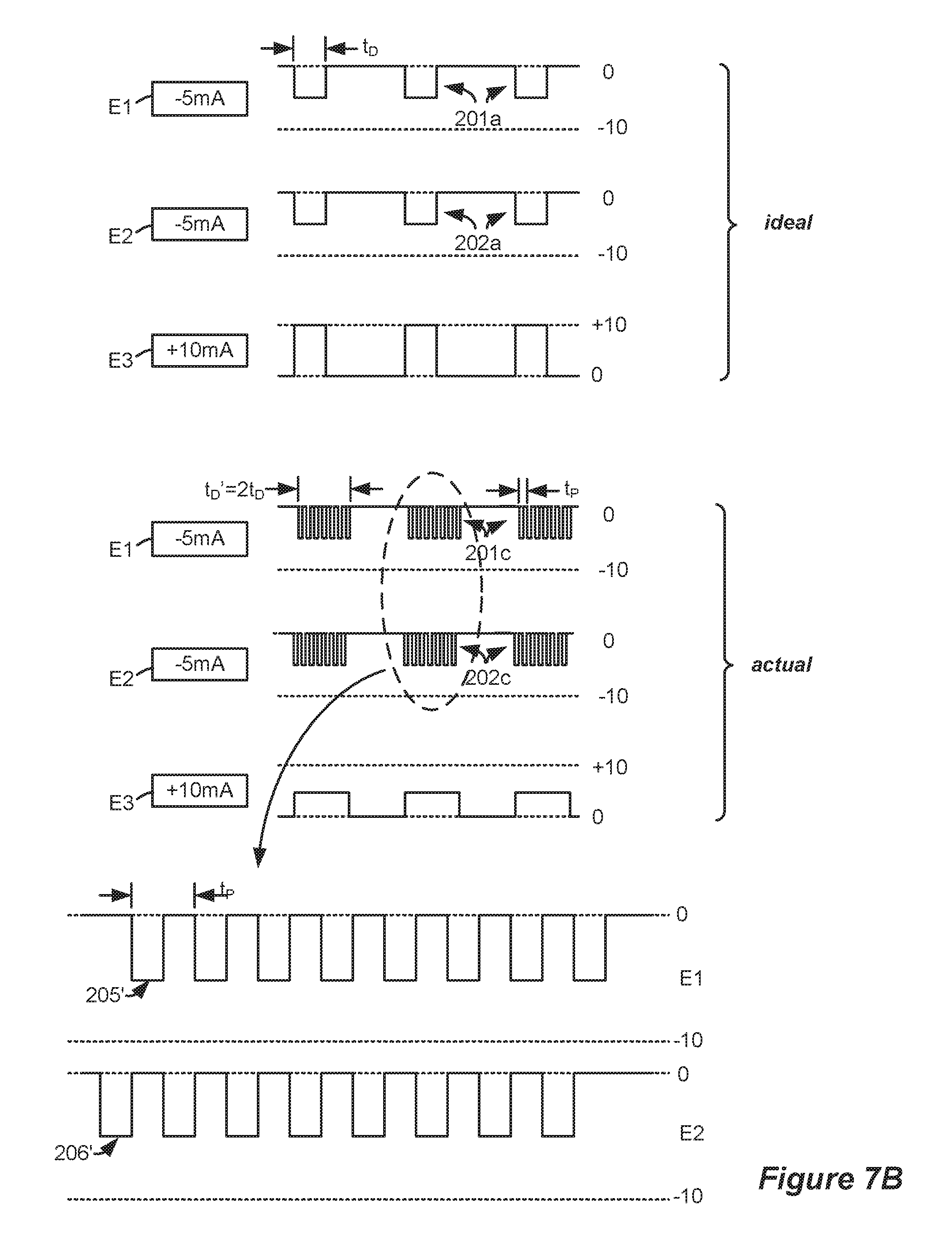
FIG. 7A illustrates an intermediary set of pulses as might be desired during current steering. As shown, electrodes E1 and E2 are desired to be simultaneously asserted as pulses 201a and 202a, each providing a 5 mA sink. This condition of simultaneity could be encountered when transferring sink current from E1 to E2, as was illustrated earlier.
The actual implementation of such idealized pulses according to an aspect of the invention comprises a reconstruction of these ideal pulses 201a and 202a as fractionalized pulses 201b and 202b which are not simultaneous. As can be seen in the magnified illustration at the bottom of FIG. 7A, only one fractionalized pulse portion 205 or 206 is asserted at any given time. As such, the fractionalized pulse portions 205 and 206 are interleaved.
The frequency of the fractionalized pulse portions 205, 206 in the illustrated example equals 1/t.sub.P, where t.sub.P comprises the pulse portion period. Because the pulse portion period t.sub.P is generally much shorter than the duration of the ideal pulses, t.sub.D, there would typically be many fractional pulse portions 205 or 206 occurring within duration t.sub.D, although only a few such portions are shown in FIG. 7A for ease of illustration.
Stimulation using fractionalized pulses 201b and 202b causes recruited neurons to react to the pulse portions 205 and 206 in an additive manner. For example, for a depolarizing sequence, the transmembrane potential will slowly depolarize on average with each additional pulse portion. The sequence of pulse portions 205 and 206 takes advantage of the non-linear membrane dynamics which tend to move a recruited neuron towards depolarization. In particular, short pulse portions will tend to open the "m" gates of the sodium channels. As the gates open, the cell membrane will tend to depolarize slightly more. A combination of pulse portions can then depolarize the membrane enough until, as with the ideal pulses 201a and 202a, an action potential is generated in the recruited neurons. In other words, the nerves recruited by the electrodes E1 and E2 will receive effective therapy even though the fractionalized pulses 201b and 202b are interrupted and non-simultaneous unlike their ideal counterparts 201a and 202a.
The pulse portion period, t.sub.P (frequency 1/t.sub.P), may be kept lower than the chronaxie time, which is approximately 100 to 150 microseconds or so (i.e., 10000 to 6666.7 Hz frequency). However t.sub.P can also exceed the chronaxie time, although in such an application higher energies (e.g., pulse portion amplitudes) might be required as explained further below. However, effectiveness in therapy, even with increasing energies, would be expected to diminish when t.sub.P exceeds 500 microseconds or so (i.e., lower than 2000 Hz).
In the illustrated example, the fractionalized pulse portions 205 and 206 have a duty cycle of approximately 50%, such that only one pulse portion 205 or 206 from fractionalized pulses 201b and 202b are asserted at any given time. Note also that the amplitude of those pulse portions 205, 206 (-10 mA) are twice what is called for in the corresponding ideal pulses 201a and 201b (-5 mA). This amplitude relates to the duty cycle of the pulse portions, and stems from the recognition that the total amount of injected charge remains an important first-order variable in effective patient therapy. Thus, when one compares the ideal pulses 201a and 202a with their fractionized actual counterparts 202a and 202b, the amount of charge (i.e., the area under their curves) is same. So, if the duty cycle of the fractionalized portions are 50%, an amplitude of twice would be indicated; if the duty cycle is 33.3% (as might occur should three electrodes need to act as either a source or sink at one time), three times the amplitude would be indicated, etc.
However, it is not strictly required that the amount of charge in the ideal and fractionalized pulses be equal, and in a given application amplitudes of the fractionalized pulse portions 205 and 206 may need to be adjusted to provide slightly more or less charge than the injected charge of the ideal pulses 201a and 202a. In one example, and as alluded to above, longer pulse portion periods might require higher amounts of charge than are represented by their ideal counterparts. For example, assuming a 50% duty cycle and a pulse portion period t.sub.P slightly above the chronaxie time, the amplitude of the fractionalized pulse portions 205 and 206 may be higher than double (e.g., 2.1 times) the amplitude of the corresponding ideal pulses 201a and 202a, resulting in a higher amount of charge. If t.sub.P is made even larger, than the amplitude of the fractionalized pulses portions could increase even further (e.g., to 2.2 times), etc.
Because of the increase in amplitude of the fractionalized pulse portions 205, 206, the current generation circuitry in the IPG 100 must be capable of sustaining higher compliance voltages. See U.S. Published Patent Application 2007/0097719, published May 3, 2007, which is incorporated herein in its entirety, for a further discussion of compliance voltage generation in IPGs.
FIG. 7B illustrates another way in which simultaneous pulses can be reconstructed in accordance with the invention. As with FIG. 7A, the ideal pulses 201a and 201b are fractionalized and interleaved as shown at 201c and 202c. However, the fractionalized pulse portions 205' and 206' have the same amplitude (-5 mA) as do their ideal pulse counterparts, but the fractionalized pulses 201c and 202c have a duration t.sub.D' of twice the duration t.sub.D of the ideal pulses. The result, as with FIG. 7A, is ideal and fractionalized pulses that are comprised of approximately the same amount of charge. While the reconstruction method of FIG. 7B does modify the duration of the ideal pulses (i.e., from t.sub.D to t.sub.D'), such pulse duration modification only affects patient therapy as a second-order variable; the more-important first-order variable of total charge remains essentially unchanged, and so patient therapy is not significantly impacted by the change in duration. Of course, assuming that the amount of charge is kept approximately the same, other durations, both longer and shorter than the duration of the ideal pulses, can be used in the actual fractionalized pulses. The two-fold duration increase shown in FIG. 7B is therefore merely exemplary.
The system may use both techniques--higher pulse amplitude (FIG. 7A) or higher pulse duration (FIG. 7B)--as convenient. For example, the logic in the IPG 100 may choose an appropriate pulse fractionalization strategy that saves energy. Or, the logic in the IPG 100 may choose fractionalization parameters to prevent saturation of the output--e.g., if the amplitude has been maximized then the pulse width or duration is increased, etc.
There are significant benefits to reconstructing the ideal pulses as fractionalized pulses as shown in FIGS. 7A and 7B. Even though the patient's nerves biologically sense simultaneous stimulation, the reality is that no more than one electrode is truly active as a source or sink at any given time, given the interleaved fractionalized pulse portions 205 and 206. Therefore, this technique, and the steering technique described subsequently in FIGS. 8A and 8B, can be implemented in IPGs having simpler architectures in which source or sink circuitry is coupleable to only a single electrode at a time.
In an actual implementation, there would be some set-up time necessary to switch current sink circuitry from E1 to E2, and so the duty cycles of the fractionalized pulse portions 205 and 206 may be less than an ideal 50% for example. However, such set-up time would be relatively short compared to the pulse portion period t.sub.P, and so such set-up time is negligible and therefore not illustrated in the figures. For example, it may take only a few 0.1 of a microsecond to switch the current from one electrode to another, i.e., from a pulse portion 205 to a pulse portion 206. However, one skilled in the art will realize that the transition times and other non-idealities will mean that the actual charge of the fractionalized pulses may only approximate the charge specified by the ideal pulses.
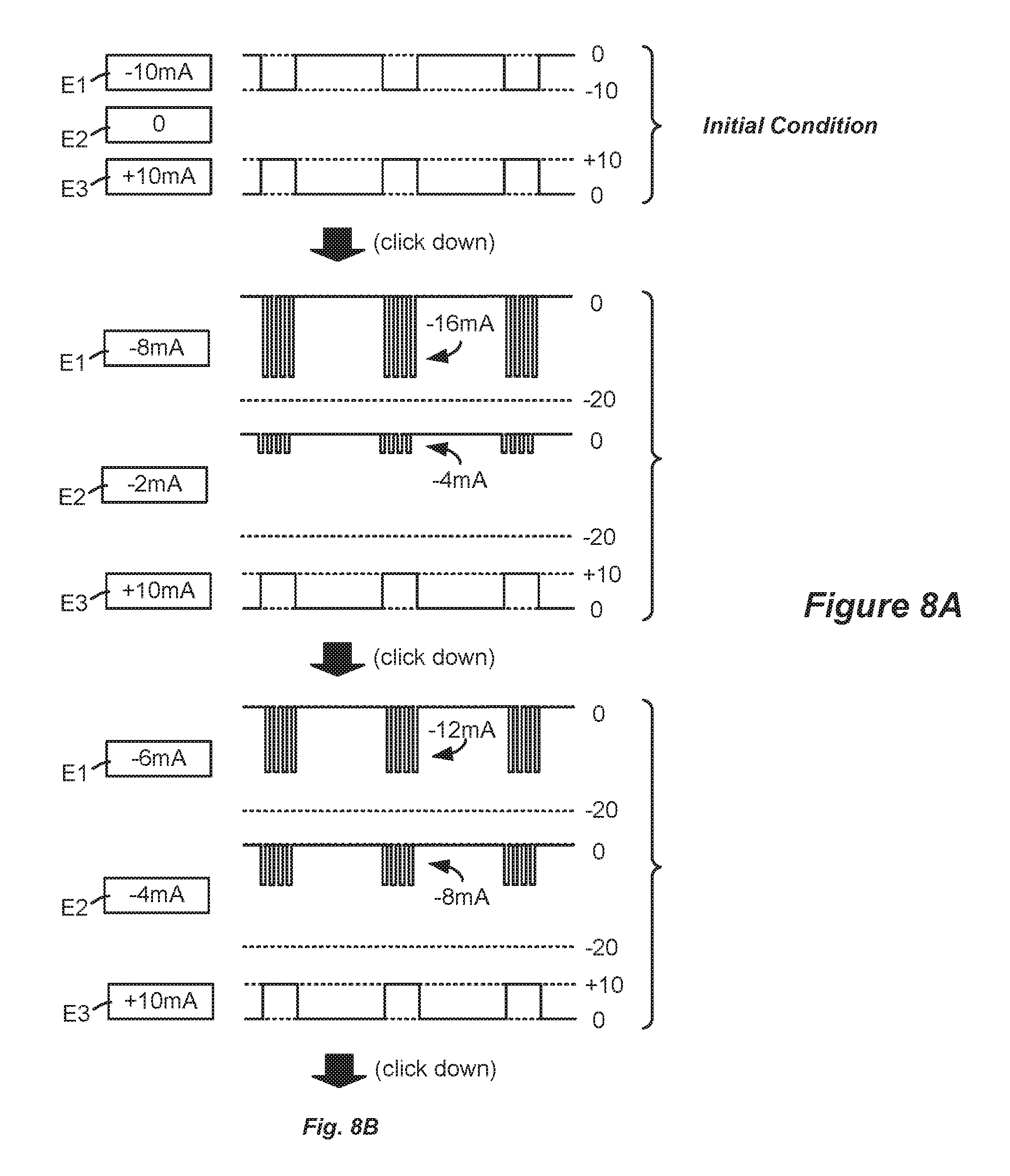
FIGS. 8A and 8B illustrate how the reconfigured fractionalized pulses can be utilized in an improved current steering scheme. As with FIGS. 5 and 6, FIGS. 8A and 8B illustrate the simple example of gradually steering 10 mA of sink current from electrode E1 to electrode E2. The initial condition at the top of FIG. 8A is defined in a single timing channel, which timing channel specifies the amplitude, duration, and frequency of the ideal stimulation pulses. Starting from that initial condition, a user (patient or clinician) selects to move an increment (e.g., 2 mA) of sink current from E1 to E2, perhaps by a downward click of a joystick on an external controller as mentioned previously. At this point, the logic in the IPG 100 recognizes the need for sink current to be simultaneously present at both E1 (8 mA) and E2 (2 mA). Accordingly, the logic in the IPG reconstructs these ideal pulses as shown in the second condition of FIG. 8A. This second condition reconfigures the pulses as fractionalized pulses. Because these pulses are fractionalized and interleaved, their amplitudes are doubled to (in this example) approximately preserve the desired amount of charge. Thus, the fractionalized pulse portions at E1 (with a duty cycle of approximately 50%), have an amplitude of approximately -16 mA over the same duration as the initial pulses, thus simulating the -8 mA pulse that is desired; the interleaved pulses portions at E2 likewise have an amplitude of approximately -4 mA to simulate the desired -2 mA pulse.
While the logic in the IPG 100 can be programmed to automatically fractionalize the pulses in a predetermined manner when necessary, it should be noted that this is only an embodiment. The decision on how to perform the fractionalization can also be made by a user with a wireless external controller. For example, a user can access a user interface on the external controller to specify fractionalization parameters such as amplitude, duration, period, etc., with such parameters being wirelessly transmitted to the nonvolatile memory storage in the IPG 100. Because external controllers are well known in the art, they are not discussed further.
Effecting such fractionalization is achieved in a preferred embodiment by re-writing the timing channel in which the initial condition was specified. In other words, moving from the initial to the second condition does not require the establishment of a second timing channel, because the logic in the IPG 100 preferably re-writes the first timing channel to add the additional electrode (E2), to specify the duty cycle and period (t.sub.P) of the first and second interleaved pulses, etc. This is an improvement over prior art current steering techniques which require the use of steering using additional timing channels, such as the '228 publication referenced earlier. In short, the presently-disclosed current steering technique requires only a single timing channel, making it amenable to IPG architectures having hardware or software capable of handling only a single timing channel. Having said this, it should be recognized that the invention can also be implemented in IPGs having a plurality of timing channels, and so is not limited to single timing channel devices.
As shown further in FIG. 8A, further user selection to steer another increment of current results in decreasing the amplitude of the fractionalize pulse portions at the transmitting electrode E1 (from -16 mA to -12 mA) while concurrently increasing the amplitude of the fractionized pulse portions at the receiving electrode E2 (from -4 mA to -8 mA). Such adjustment merely requires updating the amplitudes in the first (initial) timing channel, and does not require a second timing channel. Continuing selections eventually result in the final desired condition illustrated at the bottom of FIG. 8B, in which the full amount of sink current (-10 mA) is now present entirety at electrode E2. Because this final condition does not require electrode E1 and E2 to both sink current simultaneously, the pulses at E2 can be reconfigured with a 100% duty cycle pulse at its normal amplitude. Again, this happens by re-writing the first timing channel.
It should be understood that reference to an "electrode on the implantable stimulator device" includes electrodes on the implantable stimulator device, or the electrodes on the associated electrode leads, or any other structure for directly or indirectly stimulating tissue.
Although particular embodiments of the present invention have been shown and described, it should be understood that the above discussion is not intended to limit the present invention to these embodiments. It will be obvious to those skilled in the art that various changes and modifications may be made without departing from the spirit and scope of the present invention. Thus, the present invention is intended to cover alternatives, modifications, and equivalents that may fall within the spirit and scope of the present invention as defined by the claims.
* * * * *
References
D00000
D00001
D00002
D00003
D00004
D00005
D00006
D00007
D00008
D00009
D00010
D00011
XML
uspto.report is an independent third-party trademark research tool that is not affiliated, endorsed, or sponsored by the United States Patent and Trademark Office (USPTO) or any other governmental organization. The information provided by uspto.report is based on publicly available data at the time of writing and is intended for informational purposes only.
While we strive to provide accurate and up-to-date information, we do not guarantee the accuracy, completeness, reliability, or suitability of the information displayed on this site. The use of this site is at your own risk. Any reliance you place on such information is therefore strictly at your own risk.
All official trademark data, including owner information, should be verified by visiting the official USPTO website at www.uspto.gov. This site is not intended to replace professional legal advice and should not be used as a substitute for consulting with a legal professional who is knowledgeable about trademark law.