Tissue-removing catheter including movable distal tip
Guggenheimer , et al.
U.S. patent number 10,292,721 [Application Number 14/803,703] was granted by the patent office on 2019-05-21 for tissue-removing catheter including movable distal tip. This patent grant is currently assigned to Covidien LP. The grantee listed for this patent is Covidien LP. Invention is credited to Benjamin Fruland, Zachary Garvey, Ethan Guggenheimer, Lucas Schneider, Cory Sills.


View All Diagrams
| United States Patent | 10,292,721 |
| Guggenheimer , et al. | May 21, 2019 |
Tissue-removing catheter including movable distal tip
Abstract
A catheter includes a tissue-removing element and a tissue-containment chamber configured to receive tissue removed by the tissue-removing element. The tissue-containment chamber has a tissue-removing opening for use in removing tissue from the chamber. A closure component is associated with the tissue-removing opening for selectively opening and closing the opening.
| Inventors: | Guggenheimer; Ethan (Minnetonka, MN), Fruland; Benjamin (Blaine, MN), Schneider; Lucas (Champlin, MN), Garvey; Zachary (Stillwater, MN), Sills; Cory (Plymouth, MN) | ||||||||||
|---|---|---|---|---|---|---|---|---|---|---|---|
| Applicant: |
|
||||||||||
| Assignee: | Covidien LP (Mansfield,
MA) |
||||||||||
| Family ID: | 56555814 | ||||||||||
| Appl. No.: | 14/803,703 | ||||||||||
| Filed: | July 20, 2015 |
Prior Publication Data
| Document Identifier | Publication Date | |
|---|---|---|
| US 20170020539 A1 | Jan 26, 2017 | |
| Current U.S. Class: | 1/1 |
| Current CPC Class: | A61B 17/3207 (20130101); A61B 17/22 (20130101); A61B 17/320758 (20130101); A61B 17/320783 (20130101); A61B 2017/320004 (20130101); A61B 2017/320775 (20130101); A61B 2017/22045 (20130101); A61B 2017/22039 (20130101); A61B 2017/320064 (20130101); A61B 2017/22038 (20130101); A61B 2017/320791 (20130101) |
| Current International Class: | A61B 17/22 (20060101); A61B 17/3207 (20060101); A61B 17/32 (20060101) |
References Cited [Referenced By]
U.S. Patent Documents
| 1481078 | January 1924 | Albertson |
| 2178790 | November 1939 | Henry |
| 2701559 | February 1955 | Cooper |
| 2850007 | September 1958 | Lingley |
| 3064651 | November 1960 | Henderson |
| 3082805 | March 1963 | Royce |
| 3320957 | May 1967 | Sokolik |
| 3614953 | October 1971 | Moss |
| 3683891 | August 1972 | Eskridge et al. |
| 3705577 | December 1972 | Sierra |
| 3732858 | May 1973 | Banko |
| 3749085 | July 1973 | Wilson et al. |
| 3800783 | April 1974 | Jamshidi |
| 3815604 | June 1974 | O'Malley et al. |
| 3831585 | August 1974 | Brondy et al. |
| 3837345 | September 1974 | Matar |
| 3845375 | October 1974 | Stiebel |
| 3937222 | February 1976 | Banko |
| 3945375 | March 1976 | Banko |
| 3976077 | August 1976 | Kerfoot, Jr. |
| 3995619 | December 1976 | Glatzer |
| 4007732 | February 1977 | Kvavle et al. |
| 4020847 | May 1977 | Clark, III |
| 4030503 | June 1977 | Clark, III |
| 4034744 | July 1977 | Goldberg |
| 4038985 | August 1977 | Chiulli |
| 4112708 | September 1978 | Fukuda |
| 4177797 | December 1979 | Baylis et al. |
| 4210146 | July 1980 | Banko |
| 4273128 | June 1981 | Lary |
| 4306562 | December 1981 | Osborne |
| 4306570 | December 1981 | Matthews |
| 4349032 | September 1982 | Koyata |
| 4368730 | January 1983 | Sharrock |
| 4424045 | January 1984 | Kulischenko et al. |
| 4436091 | March 1984 | Banko |
| 4445509 | May 1984 | Auth |
| 4490139 | December 1984 | Huizenga et al. |
| 4494057 | January 1985 | Hotta |
| 4512344 | April 1985 | Barber |
| 4589412 | May 1986 | Kensey |
| 4603694 | August 1986 | Wheeler |
| 4620547 | November 1986 | Boebel |
| 4631052 | December 1986 | Kensey |
| 4646719 | March 1987 | Neuman et al. |
| 4646736 | March 1987 | Auth |
| 4646738 | March 1987 | Trott |
| 4649919 | March 1987 | Thimsen et al. |
| 4653496 | March 1987 | Bundy et al. |
| 4664112 | May 1987 | Kensey et al. |
| 4669469 | June 1987 | Gifford, III et al. |
| 4679558 | July 1987 | Kensey et al. |
| 4686982 | August 1987 | Nash |
| 4692141 | September 1987 | Mahurkar |
| 4696298 | September 1987 | Higgins et al. |
| 4696667 | September 1987 | Masch |
| 4705038 | November 1987 | Sjostrom |
| 4706671 | November 1987 | Weinrib |
| 4728319 | March 1988 | Masch |
| 4729763 | March 1988 | Henrie |
| 4730616 | March 1988 | Frisbie et al. |
| 4732154 | March 1988 | Shiber |
| 4733662 | March 1988 | Desatnick et al. |
| 4745919 | May 1988 | Bundey et al. |
| 4747406 | May 1988 | Nash |
| 4747821 | May 1988 | Kensey et al. |
| 4749376 | June 1988 | Kensey et al. |
| 4754755 | July 1988 | Husted |
| 4757819 | July 1988 | Yokoi et al. |
| 4765332 | August 1988 | Fischell et al. |
| 4771774 | September 1988 | Simpson et al. |
| 4781186 | November 1988 | Simpson et al. |
| 4784636 | November 1988 | Rydell |
| 4790812 | December 1988 | Hawkins, Jr. et al. |
| 4794931 | January 1989 | Yock |
| 4817613 | April 1989 | Jaraczewski et al. |
| 4819634 | April 1989 | Shiber |
| 4819635 | April 1989 | Shapiro |
| 4838268 | June 1989 | Keith et al. |
| 4842579 | June 1989 | Shiber |
| 4844064 | July 1989 | Thimsen et al. |
| 4848343 | July 1989 | Wallsten et al. |
| 4850957 | July 1989 | Summers |
| 4857046 | August 1989 | Stevens et al. |
| 4867157 | September 1989 | McGurk-Burleson et al. |
| 4870953 | October 1989 | DonMichael et al. |
| 4883458 | November 1989 | Shiber |
| 4886061 | December 1989 | Fischell et al. |
| 4886490 | December 1989 | Shiber |
| 4887613 | December 1989 | Farr et al. |
| 4894051 | January 1990 | Shiber |
| 4899757 | February 1990 | Pope, Jr. et al. |
| 4919133 | April 1990 | Chiang |
| 4923462 | May 1990 | Stevens |
| 4926858 | May 1990 | Gifford, III et al. |
| 4928693 | May 1990 | Goodin et al. |
| 4936987 | June 1990 | Persinksi et al. |
| RE33258 | July 1990 | Onik et al. |
| 4950238 | August 1990 | Sullivan |
| 4954338 | September 1990 | Mattox |
| 4957482 | September 1990 | Shiber |
| 4966604 | October 1990 | Reiss |
| 4973409 | November 1990 | Cook |
| 4979939 | December 1990 | Shiber |
| 4979951 | December 1990 | Simpson |
| 4986807 | January 1991 | Farr |
| 4990134 | February 1991 | Auth |
| 4994067 | February 1991 | Summers |
| 4997435 | March 1991 | Demeter |
| 5000185 | March 1991 | Yock |
| 5002553 | March 1991 | Shiber |
| 5003918 | April 1991 | Olson et al. |
| 5007896 | April 1991 | Shiber |
| 5009659 | April 1991 | Hamlin et al. |
| 5019088 | May 1991 | Farr |
| 5024234 | June 1991 | Leary et al. |
| 5024651 | June 1991 | Shiber |
| 5026384 | June 1991 | Farr et al. |
| 5029588 | July 1991 | Yock et al. |
| 5030201 | July 1991 | Palestrant |
| 5047040 | September 1991 | Simpson et al. |
| 5049124 | September 1991 | Bales, Jr. |
| 5053044 | October 1991 | Mueller et al. |
| 5054492 | October 1991 | Scribner et al. |
| 5064435 | November 1991 | Porter |
| 5071425 | December 1991 | Gifford et al. |
| 5074841 | December 1991 | Ademovic et al. |
| 5077506 | December 1991 | Krause et al. |
| 5078722 | January 1992 | Stevens |
| 5078723 | January 1992 | Dance et al. |
| 5084010 | January 1992 | Plaia et al. |
| 5085662 | February 1992 | Willard |
| 5087265 | February 1992 | Summers |
| 5092839 | March 1992 | Kipperman |
| 5092873 | March 1992 | Simpson et al. |
| 5095911 | March 1992 | Pomeranz |
| 5100423 | March 1992 | Fearnot |
| 5100424 | March 1992 | Jang et al. |
| 5100426 | March 1992 | Nixon |
| 5110822 | May 1992 | Sherba et al. |
| 5112345 | May 1992 | Farr |
| 5114399 | May 1992 | Kovalcheck |
| 5115814 | May 1992 | Griffith et al. |
| 5120323 | June 1992 | Shockey et al. |
| 5127902 | July 1992 | Fischeil |
| 5127917 | July 1992 | Niederhauser et al. |
| 5135531 | August 1992 | Shiber |
| 5154705 | October 1992 | Fleischhacker et al. |
| 5154724 | October 1992 | Andrews |
| 5165421 | November 1992 | Fleischhacker et al. |
| 5176693 | January 1993 | Pannek, Jr. |
| 5178625 | January 1993 | Groshong |
| 5181920 | January 1993 | Mueller et al. |
| 5183432 | February 1993 | Noguchi |
| 5190528 | March 1993 | Fonger et al. |
| 5192291 | March 1993 | Pannek, Jr. |
| 5195956 | March 1993 | Stockmeier |
| 5211651 | May 1993 | Reger et al. |
| 5217474 | June 1993 | Zacca et al. |
| 5222966 | June 1993 | Perkins et al. |
| 5224488 | July 1993 | Neuffer |
| 5224945 | July 1993 | Pannek, Jr. |
| 5224949 | July 1993 | Gomringer et al. |
| 5226909 | July 1993 | Evans et al. |
| 5226910 | July 1993 | Kajiyama et al. |
| 5234451 | August 1993 | Osypka |
| 5242460 | September 1993 | Klein et al. |
| 5242461 | September 1993 | Kortenbach et al. |
| 5250059 | October 1993 | Andreas et al. |
| 5250065 | October 1993 | Clement et al. |
| 5263928 | November 1993 | Trauthen et al. |
| 5263959 | November 1993 | Fischell |
| 5267955 | December 1993 | Hanson |
| 5267982 | December 1993 | Sylvanowicz |
| 5269793 | December 1993 | Simpson et al. |
| 5273526 | December 1993 | Dance et al. |
| 5282484 | February 1994 | Reger |
| 5284486 | February 1994 | Kotula et al. |
| 5285795 | February 1994 | Ryan et al. |
| 5295493 | March 1994 | Radisch, Jr. |
| 5300085 | April 1994 | Yock |
| 5306294 | April 1994 | Winston et al. |
| 5308354 | May 1994 | Zacca et al. |
| 5312425 | May 1994 | Evans et al. |
| 5312427 | May 1994 | Shturman |
| 5314438 | May 1994 | Shturman |
| 5318032 | June 1994 | Lonsbury et al. |
| 5318528 | June 1994 | Heaven et al. |
| 5318576 | June 1994 | Plassche, Jr. et al. |
| 5321501 | June 1994 | Swanson et al. |
| 5322508 | June 1994 | Viera |
| 5350390 | September 1994 | Sher |
| 5356418 | October 1994 | Shturman |
| 5358472 | October 1994 | Vance et al. |
| 5358485 | October 1994 | Vance et al. |
| 5360432 | November 1994 | Shturman |
| 5366463 | November 1994 | Ryan |
| 5368035 | November 1994 | Hamm et al. |
| 5370609 | December 1994 | Drasler et al. |
| 5370651 | December 1994 | Summers |
| 5372601 | December 1994 | Lary |
| 5372602 | December 1994 | Burke |
| 5373619 | December 1994 | Fleischhacker et al. |
| 5373849 | December 1994 | Maroney et al. |
| 5377682 | January 1995 | Ueno et al. |
| 5378234 | January 1995 | Hammerslag et al. |
| 5383460 | January 1995 | Jang et al. |
| 5395311 | March 1995 | Andrews |
| 5395313 | March 1995 | Naves et al. |
| 5395335 | March 1995 | Jung |
| 5397345 | March 1995 | Lazarus |
| 5402790 | April 1995 | Jang et al. |
| 5403334 | April 1995 | Evans et al. |
| 5409454 | April 1995 | Fischell et al. |
| 5413107 | May 1995 | Oakley et al. |
| 5419774 | May 1995 | Willard et al. |
| 5423740 | June 1995 | Sullivan |
| 5423799 | June 1995 | Shiu |
| 5423838 | June 1995 | Willard |
| 5423846 | June 1995 | Fischell |
| 5427107 | June 1995 | Milo et al. |
| 5429136 | July 1995 | Milo et al. |
| 5431673 | July 1995 | Summers et al. |
| 5441510 | August 1995 | Simpson et al. |
| 5443446 | August 1995 | Shturman |
| 5443497 | August 1995 | Venbrux |
| 5444078 | August 1995 | Yu et al. |
| 5445155 | August 1995 | Sieben |
| 5449369 | September 1995 | Imran |
| 5451233 | September 1995 | Yock |
| 5454809 | October 1995 | Janssen |
| 5456667 | October 1995 | Ham et al. |
| 5456689 | October 1995 | Kresch et al. |
| 5458585 | October 1995 | Salmon et al. |
| 5459570 | October 1995 | Swanson et al. |
| 5464016 | November 1995 | Nicholas et al. |
| 5470415 | November 1995 | Perkins et al. |
| 5485042 | January 1996 | Burke et al. |
| 5485840 | January 1996 | Bauman |
| 5487729 | January 1996 | Avellanet et al. |
| 5489295 | February 1996 | Piplani et al. |
| 5491524 | February 1996 | Hellmuth et al. |
| 5496267 | March 1996 | Drasler et al. |
| 5501694 | March 1996 | Ressemann et al. |
| 5503155 | April 1996 | Salmon et al. |
| 5505210 | April 1996 | Clement |
| 5507292 | April 1996 | Jang et al. |
| 5507760 | April 1996 | Wynne et al. |
| 5507761 | April 1996 | Duer |
| 5507795 | April 1996 | Chiang et al. |
| 5512044 | April 1996 | Duer |
| 5514115 | May 1996 | Frantzen et al. |
| 5520189 | May 1996 | Malinowski et al. |
| 5522825 | June 1996 | Kropf et al. |
| 5522880 | June 1996 | Barone et al. |
| 5527292 | June 1996 | Adams et al. |
| 5527298 | June 1996 | Vance et al. |
| 5527325 | June 1996 | Conley et al. |
| 5531685 | July 1996 | Hemmer et al. |
| 5531690 | July 1996 | Solar |
| 5531700 | July 1996 | Moore et al. |
| 5540707 | July 1996 | Ressemann et al. |
| 5549601 | August 1996 | McIntyre et al. |
| 5554163 | September 1996 | Shturman |
| 5556408 | September 1996 | Farhat |
| 5558093 | September 1996 | Pomeranz |
| 5562726 | October 1996 | Chuter |
| 5562728 | October 1996 | Lazarus |
| 5569275 | October 1996 | Kotula et al. |
| 5569276 | October 1996 | Jang et al. |
| 5569277 | October 1996 | Evans et al. |
| 5569279 | October 1996 | Rainin |
| 5570693 | November 1996 | Jang et al. |
| 5571122 | November 1996 | Kelly et al. |
| 5571130 | November 1996 | Simpson et al. |
| 5575817 | November 1996 | Martin |
| 5584842 | December 1996 | Fogarty et al. |
| 5584843 | December 1996 | Wulfman et al. |
| 5609605 | March 1997 | Marshall et al. |
| 5618293 | April 1997 | Sample et al. |
| 5620447 | April 1997 | Smith et al. |
| 5624457 | April 1997 | Farley et al. |
| 5626562 | May 1997 | Castro |
| 5626576 | May 1997 | Janssen |
| 5628761 | May 1997 | Rizik |
| 5632754 | May 1997 | Farley et al. |
| 5632755 | May 1997 | Nordgren et al. |
| 5634464 | June 1997 | Jang et al. |
| 5643296 | July 1997 | Hundertmark et al. |
| 5643298 | July 1997 | Nordgren et al. |
| 5649941 | July 1997 | Lary |
| 5660180 | August 1997 | Malinowski et al. |
| 5662671 | September 1997 | Barbut et al. |
| 5665098 | September 1997 | Kelly et al. |
| 5669920 | September 1997 | Conley et al. |
| 5674232 | October 1997 | Halliburton |
| 5676696 | October 1997 | Marcade |
| 5676697 | October 1997 | McDonald |
| 5681336 | October 1997 | Clement et al. |
| 5682897 | November 1997 | Pomeranz |
| 5683449 | November 1997 | Marcade |
| 5683453 | November 1997 | Palmaz |
| 5688234 | November 1997 | Frisbie |
| 5695506 | December 1997 | Pike |
| 5695507 | December 1997 | Auth et al. |
| 5697944 | December 1997 | Lary |
| 5700240 | December 1997 | Barwick, Jr. et al. |
| 5700687 | December 1997 | Finn |
| 5707350 | January 1998 | Krause et al. |
| 5707376 | January 1998 | Kavteladze et al. |
| 5707383 | January 1998 | Bays et al. |
| 5709698 | January 1998 | Adams et al. |
| 5713913 | February 1998 | Lary et al. |
| 5715825 | February 1998 | Crowley |
| 5716410 | February 1998 | Wang et al. |
| 5720735 | February 1998 | Dorros |
| 5724977 | March 1998 | Yock et al. |
| 5728123 | March 1998 | Lemelson et al. |
| 5733296 | March 1998 | Rogers et al. |
| 5735816 | April 1998 | Lieber et al. |
| 5741270 | April 1998 | Hansen et al. |
| 5766192 | June 1998 | Zacca |
| 5772674 | June 1998 | Nakhjavan |
| 5775327 | July 1998 | Randolph et al. |
| 5776114 | July 1998 | Frantzen et al. |
| 5776153 | July 1998 | Rees |
| 5779643 | July 1998 | Lum et al. |
| 5779673 | July 1998 | Roth et al. |
| 5779721 | July 1998 | Nash |
| 5779722 | July 1998 | Shturman et al. |
| 5792157 | August 1998 | Mische et al. |
| 5797949 | August 1998 | Parodi |
| 5799655 | September 1998 | Jang et al. |
| 5807329 | September 1998 | Gelman |
| 5810867 | September 1998 | Zarbatany et al. |
| 5816923 | October 1998 | Milo et al. |
| 5820592 | October 1998 | Hammerslag |
| 5823971 | October 1998 | Robinson et al. |
| 5824039 | October 1998 | Piplani et al. |
| 5824055 | October 1998 | Spiridigliozzi et al. |
| 5827201 | October 1998 | Samson et al. |
| 5827229 | October 1998 | Auth et al. |
| 5827304 | October 1998 | Hart |
| 5827322 | October 1998 | Williams |
| 5830224 | November 1998 | Cohn et al. |
| 5836957 | November 1998 | Schulz et al. |
| 5843022 | December 1998 | Willard et al. |
| 5843103 | December 1998 | Wulfman |
| 5843161 | December 1998 | Solovay |
| 5855563 | January 1999 | Kaplan et al. |
| 5865748 | February 1999 | Co et al. |
| 5868685 | February 1999 | Powell et al. |
| 5868767 | February 1999 | Farley et al. |
| 5871536 | February 1999 | Lazarus |
| 5873882 | February 1999 | Straub et al. |
| 5876414 | March 1999 | Straub |
| 5879397 | March 1999 | Kalberer et al. |
| 5883458 | March 1999 | Sumita et al. |
| 5888201 | March 1999 | Stinson et al. |
| 5895399 | April 1999 | Barbut et al. |
| 5895402 | April 1999 | Hundertmark et al. |
| 5902245 | May 1999 | Yock |
| 5910150 | June 1999 | Saadat |
| 5911734 | June 1999 | Tsugita et al. |
| 5916210 | June 1999 | Winston |
| 5922003 | July 1999 | Anctil et al. |
| 5935108 | August 1999 | Katoh et al. |
| 5938645 | August 1999 | Gordon |
| 5938671 | August 1999 | Katoh et al. |
| 5938672 | August 1999 | Nash |
| 5941869 | August 1999 | Patterson et al. |
| 5947985 | September 1999 | Imran |
| 5948184 | September 1999 | Frantzen et al. |
| 5951480 | September 1999 | White et al. |
| 5951482 | September 1999 | Winston et al. |
| 5954745 | September 1999 | Gertler et al. |
| 5968064 | October 1999 | Selmon et al. |
| 5972019 | October 1999 | Engelson et al. |
| 5985397 | November 1999 | Witt et al. |
| 5989281 | November 1999 | Barbut et al. |
| 5997557 | December 1999 | Barbut et al. |
| 6001112 | December 1999 | Taylor |
| 6010449 | January 2000 | Selmon et al. |
| 6010522 | January 2000 | Barbut et al. |
| 6013072 | January 2000 | Winston et al. |
| 6019778 | February 2000 | Wislon et al. |
| 6022362 | February 2000 | Lee et al. |
| 6027450 | February 2000 | Brown et al. |
| 6027460 | February 2000 | Shturman |
| 6027514 | February 2000 | Stine et al. |
| 6032673 | March 2000 | Savage et al. |
| 6036646 | March 2000 | Barthe et al. |
| 6036656 | March 2000 | Slater |
| 6036707 | March 2000 | Spaulding |
| 6048349 | April 2000 | Winston et al. |
| 6050949 | April 2000 | White et al. |
| 6063093 | May 2000 | Winston et al. |
| 6066153 | May 2000 | Lev |
| 6068603 | May 2000 | Suzuki |
| 6068638 | May 2000 | Makower |
| 6081738 | June 2000 | Hinohara et al. |
| RE36764 | July 2000 | Zacca et al. |
| 6095990 | August 2000 | Parodi |
| 6099542 | August 2000 | Cohn et al. |
| 6106515 | August 2000 | Winston et al. |
| 6110121 | August 2000 | Lenker |
| 6120515 | September 2000 | Rogers et al. |
| 6120516 | September 2000 | Selmon et al. |
| 6126649 | October 2000 | VanTassel et al. |
| 6129734 | October 2000 | Shturman et al. |
| 6134003 | October 2000 | Tearney et al. |
| 6152909 | November 2000 | Bagaoisan et al. |
| 6152938 | November 2000 | Curry |
| 6156046 | December 2000 | Passafaro et al. |
| 6157852 | December 2000 | Selmon et al. |
| 6159195 | December 2000 | Ha et al. |
| 6159225 | December 2000 | Makower |
| 6165127 | December 2000 | Crowley |
| 6179859 | January 2001 | Bates et al. |
| 6183432 | February 2001 | Milo |
| 6187025 | February 2001 | Machek |
| 6190353 | February 2001 | Makower et al. |
| 6191862 | February 2001 | Swanson et al. |
| 6193676 | February 2001 | Winston et al. |
| 6196963 | March 2001 | Williams |
| 6206898 | March 2001 | Honeycutt et al. |
| 6217527 | April 2001 | Selmon et al. |
| 6217549 | April 2001 | Selmon et al. |
| 6217595 | April 2001 | Shturman et al. |
| 6221049 | April 2001 | Selmon et al. |
| 6221332 | April 2001 | Thumm et al. |
| 6228049 | May 2001 | Schroeder et al. |
| 6228076 | May 2001 | Winston et al. |
| 6231546 | May 2001 | Milo et al. |
| 6231549 | May 2001 | Noecker et al. |
| 6235000 | May 2001 | Milo et al. |
| 6238405 | May 2001 | Findlay, III et al. |
| 6241667 | June 2001 | Vetter et al. |
| 6241744 | June 2001 | Imran et al. |
| 6245012 | June 2001 | Kleshinski |
| 6258052 | July 2001 | Milo |
| 6263236 | July 2001 | Kasinkas et al. |
| 6264611 | July 2001 | Ishikawa et al. |
| 6266550 | July 2001 | Selmon et al. |
| 6277138 | August 2001 | Levinson et al. |
| 6283951 | September 2001 | Flaherty et al. |
| 6283983 | September 2001 | Makower et al. |
| 6299622 | October 2001 | Snow et al. |
| 6299623 | October 2001 | Wulfman |
| 6302875 | October 2001 | Makower et al. |
| 6305834 | October 2001 | Schubert et al. |
| 6312444 | November 2001 | Barbut |
| 6319242 | November 2001 | Patterson et al. |
| 6319275 | November 2001 | Lashinski et al. |
| 6330884 | December 2001 | Kim |
| 6355005 | March 2002 | Powell et al. |
| 6361545 | March 2002 | Macoviak et al. |
| 6375615 | April 2002 | Flaherty et al. |
| 6383195 | May 2002 | Richard |
| 6383205 | May 2002 | Samson et al. |
| 6394976 | May 2002 | Winston et al. |
| 6398798 | June 2002 | Selmon et al. |
| 6422736 | July 2002 | Antonaides et al. |
| 6423081 | July 2002 | Lee et al. |
| 6425870 | July 2002 | Flesch |
| 6428551 | August 2002 | Hall et al. |
| 6428552 | August 2002 | Sparks |
| 6443966 | September 2002 | Shiu |
| 6445939 | September 2002 | Swanson et al. |
| 6447525 | September 2002 | Follmer et al. |
| 6451036 | September 2002 | Heitzmann et al. |
| 6454779 | September 2002 | Taylor |
| 6475226 | November 2002 | Belef et al. |
| 6482217 | November 2002 | Pintor et al. |
| 6497711 | December 2002 | Plaia et al. |
| 6501551 | December 2002 | Tearney et al. |
| 6520975 | February 2003 | Branco |
| RE38018 | March 2003 | Anctil et al. |
| 6532380 | March 2003 | Close et al. |
| 6533749 | March 2003 | Mitusina et al. |
| 6561998 | May 2003 | Roth et al. |
| 6565588 | May 2003 | Clement et al. |
| 6569177 | May 2003 | Dillard et al. |
| 6592526 | July 2003 | Lenker |
| 6620180 | September 2003 | Bays et al. |
| 6623437 | September 2003 | Hinchliffe et al. |
| 6623495 | September 2003 | Findlay, III et al. |
| 6623496 | September 2003 | Snow et al. |
| 6629953 | October 2003 | Boyd |
| 6638233 | October 2003 | Corvi et al. |
| RE38335 | November 2003 | Aust et al. |
| 6652505 | November 2003 | Tsugita |
| 6652548 | November 2003 | Evans et al. |
| 6656195 | December 2003 | Peters et al. |
| 6666874 | December 2003 | Heitzmann et al. |
| 6682543 | January 2004 | Barbut et al. |
| 6733511 | May 2004 | Hall et al. |
| 6740103 | May 2004 | Hall et al. |
| 6746462 | June 2004 | Selmon et al. |
| 6764495 | July 2004 | Lee et al. |
| 6790204 | September 2004 | Zadno-Azizi et al. |
| 6790215 | September 2004 | Findlay, III et al. |
| 6818001 | November 2004 | Wulfman et al. |
| 6830577 | December 2004 | Nash et al. |
| 6843797 | January 2005 | Nash et al. |
| 6849068 | February 2005 | Bagaoisan et al. |
| 6863676 | March 2005 | Lee et al. |
| 6911026 | June 2005 | Hall et al. |
| 6970732 | November 2005 | Winston et al. |
| 6997934 | February 2006 | Snow et al. |
| 7153315 | December 2006 | Miller |
| 7172610 | February 2007 | Heitzmann et al. |
| 7208511 | April 2007 | Williams et al. |
| 7235088 | June 2007 | Pintor et al. |
| 7318831 | January 2008 | Alvarez et al. |
| 7388495 | June 2008 | Fallin et al. |
| 7479148 | January 2009 | Beaupre |
| 7488322 | February 2009 | Brunnett et al. |
| 7524289 | April 2009 | Lenker |
| 7603166 | October 2009 | Casscells, III et al. |
| 7708749 | May 2010 | Simpson et al. |
| 7713235 | May 2010 | Torrance et al. |
| 7713279 | May 2010 | Simpson et al. |
| 7729745 | June 2010 | Maschke |
| 7734332 | June 2010 | Sher |
| 7753852 | July 2010 | Maschke |
| 7758599 | July 2010 | Snow et al. |
| 7771444 | August 2010 | Patel et al. |
| 7887556 | February 2011 | Simpson et al. |
| 8192452 | June 2012 | Moberg |
| 8574249 | November 2013 | Moberg |
| 2001/0000041 | March 2001 | Selmon et al. |
| 2001/0031784 | October 2001 | Petersen et al. |
| 2001/0031981 | October 2001 | Evans et al. |
| 2001/0044622 | November 2001 | Vardi et al. |
| 2001/0049500 | December 2001 | VanTassel et al. |
| 2002/0019644 | February 2002 | Hastings et al. |
| 2002/0022788 | February 2002 | Corvi et al. |
| 2002/0058904 | May 2002 | Boock et al. |
| 2002/0077373 | June 2002 | Hudson |
| 2002/0077642 | June 2002 | Patel et al. |
| 2002/0095141 | July 2002 | Belef et al. |
| 2002/0103459 | August 2002 | Sparks et al. |
| 2002/0177800 | November 2002 | Bagaoisan et al. |
| 2002/0188307 | December 2002 | Pintor et al. |
| 2003/0018346 | January 2003 | Follmer et al. |
| 2003/0023263 | January 2003 | Krolik et al. |
| 2003/0093098 | May 2003 | Heitzmann et al. |
| 2003/0120295 | June 2003 | Simpson et al. |
| 2003/0125757 | July 2003 | Patel et al. |
| 2003/0125758 | July 2003 | Simpson et al. |
| 2003/0163126 | August 2003 | West, Jr. |
| 2003/0199747 | October 2003 | Michlitsch et al. |
| 2003/0206484 | November 2003 | Childers et al. |
| 2003/0229369 | December 2003 | Findlay, III et al. |
| 2004/0006358 | January 2004 | Wulfman et al. |
| 2004/0049225 | March 2004 | Denison |
| 2004/0167553 | August 2004 | Simpson et al. |
| 2004/0167554 | August 2004 | Simpson et al. |
| 2004/0193034 | September 2004 | Wasicek et al. |
| 2004/0210245 | October 2004 | Erickson et al. |
| 2005/0004585 | January 2005 | Hall et al. |
| 2005/0004594 | January 2005 | Nool et al. |
| 2005/0021063 | January 2005 | Hall et al. |
| 2005/0042239 | February 2005 | Lipiecki et al. |
| 2005/0090845 | April 2005 | Boyd |
| 2005/0090849 | April 2005 | Adams |
| 2005/0177068 | August 2005 | Simpson |
| 2005/0216018 | September 2005 | Sennett |
| 2005/0222596 | October 2005 | Maschke |
| 2005/0222663 | October 2005 | Simpson et al. |
| 2006/0015126 | January 2006 | Sher |
| 2006/0235334 | October 2006 | Corvi et al. |
| 2006/0259052 | November 2006 | Pintor et al. |
| 2007/0010840 | January 2007 | Rosenthal et al. |
| 2007/0038061 | February 2007 | Huennekens et al. |
| 2007/0049958 | March 2007 | Adams |
| 2007/0135712 | June 2007 | Maschke |
| 2007/0135886 | June 2007 | Maschke |
| 2007/0167824 | July 2007 | Lee et al. |
| 2007/0225739 | September 2007 | Pintor et al. |
| 2007/0265647 | November 2007 | Bonnette et al. |
| 2007/0276419 | November 2007 | Rosenthal |
| 2008/0001643 | January 2008 | Lee |
| 2008/0004644 | January 2008 | To et al. |
| 2008/0004645 | January 2008 | To et al. |
| 2008/0004646 | January 2008 | To et al. |
| 2008/0004647 | January 2008 | To et al. |
| 2008/0045986 | February 2008 | To et al. |
| 2008/0051812 | February 2008 | Schmitz et al. |
| 2008/0065124 | March 2008 | Olson |
| 2008/0065125 | March 2008 | Olson |
| 2008/0097403 | April 2008 | Donaldson et al. |
| 2008/0125799 | May 2008 | Adams |
| 2008/0161840 | July 2008 | Osiroff et al. |
| 2008/0177139 | July 2008 | Courtney et al. |
| 2008/0208227 | August 2008 | Kadykowski et al. |
| 2008/0249553 | October 2008 | Gruber et al. |
| 2008/0312673 | December 2008 | Viswanathan et al. |
| 2009/0012548 | January 2009 | Thatcher et al. |
| 2009/0018565 | January 2009 | To et al. |
| 2009/0018566 | January 2009 | Escudero et al. |
| 2009/0138031 | May 2009 | Tsukernik et al. |
| 2009/0187203 | July 2009 | Corvi et al. |
| 2009/0216125 | August 2009 | Lenker |
| 2009/0216180 | August 2009 | Lee et al. |
| 2009/0226063 | September 2009 | Rangwala et al. |
| 2009/0234378 | September 2009 | Escudero et al. |
| 2009/0270888 | October 2009 | Patel et al. |
| 2009/0275966 | November 2009 | Mitusina |
| 2009/0299394 | December 2009 | Simpson et al. |
| 2009/0306689 | December 2009 | Welty et al. |
| 2010/0030216 | February 2010 | Arcenio |
| 2010/0049225 | February 2010 | To et al. |
| 2010/0130996 | May 2010 | Doud et al. |
| 2010/0198240 | August 2010 | Simpson et al. |
| 2010/0241147 | September 2010 | Maschke |
| 2010/0280534 | November 2010 | Sher |
| 2010/0292721 | November 2010 | Moberg |
| 2010/0298850 | November 2010 | Snow et al. |
| 2010/0312263 | December 2010 | Moberg et al. |
| 2011/0004107 | January 2011 | Rosenthal et al. |
| 2011/0022069 | January 2011 | Mitusina |
| 2011/0040315 | February 2011 | To et al. |
| 2011/0130777 | June 2011 | Zhang et al. |
| 2011/0144673 | June 2011 | Zhang et al. |
| 2011/0152841 | June 2011 | Nemoto |
| 2014/0222044 | August 2014 | Ladd et al. |
| 2015/0057690 | February 2015 | Simpson et al. |
| 2000621 | Apr 1990 | CA | |||
| 3732236 | Dec 1988 | DE | |||
| 8900059 | May 1989 | DE | |||
| 93 03 531 | Jul 1994 | DE | |||
| 44 44 166 | Jun 1996 | DE | |||
| 29722136 | May 1999 | DE | |||
| 0086048 | Aug 1983 | EP | |||
| 0 107 009 | May 1984 | EP | |||
| 0 229 620 | Jul 1987 | EP | |||
| 0291170 | Nov 1988 | EP | |||
| 0 302 701 | Feb 1989 | EP | |||
| 0330843 | Sep 1989 | EP | |||
| 0373927 | Jun 1990 | EP | |||
| 0421457 | Apr 1991 | EP | |||
| 0 431 752 | Jun 1991 | EP | |||
| 0448859 | Oct 1991 | EP | |||
| 0463798 | Jan 1992 | EP | |||
| 0 490 565 | Jun 1992 | EP | |||
| 0514810 | Nov 1992 | EP | |||
| 0 526 042 | Feb 1993 | EP | |||
| 0533320 | Mar 1993 | EP | |||
| 0 608 911 | Aug 1994 | EP | |||
| 0 608 912 | Aug 1994 | EP | |||
| 0 611 522 | Aug 1994 | EP | |||
| 0 648 414 | Apr 1995 | EP | |||
| 0657140 | Jun 1995 | EP | |||
| 0 680 695 | Nov 1998 | EP | |||
| 0 983 749 | Mar 2000 | EP | |||
| 1 767 159 | Mar 2007 | EP | |||
| 1 875 871 | Jan 2008 | EP | |||
| 2093353 | Sep 1982 | GB | |||
| 2 115 829 | Sep 1983 | GB | |||
| 2210965 | Jun 1989 | GB | |||
| 2-206452 A | Aug 1990 | JP | |||
| 2271847 | Nov 1990 | JP | |||
| 3186256 | Aug 1991 | JP | |||
| 4200459 | Jul 1992 | JP | |||
| 5042162 | Feb 1993 | JP | |||
| 5056984 | Mar 1993 | JP | |||
| 5184679 | Jul 1993 | JP | |||
| 6269460 | Sep 1994 | JP | |||
| 7075611 | Aug 1995 | JP | |||
| 442795 | Sep 1974 | SU | |||
| 665908 | Jun 1979 | SU | |||
| WO 8906517 | Jul 1989 | WO | |||
| WO 92/07500 | May 1992 | WO | |||
| WO 9313716 | Jul 1993 | WO | |||
| WO 9313717 | Jul 1993 | WO | |||
| WO 9521576 | Aug 1995 | WO | |||
| WO 9611648 | Apr 1996 | WO | |||
| WO 9746164 | Dec 1997 | WO | |||
| WO 9804199 | Feb 1998 | WO | |||
| WO 9824372 | Jun 1998 | WO | |||
| WO 99/39648 | Aug 1999 | WO | |||
| WO 9952454 | Oct 1999 | WO | |||
| WO 00/30531 | Jun 2000 | WO | |||
| WO 00/54735 | Sep 2000 | WO | |||
| WO 00/62913 | Oct 2000 | WO | |||
| WO 00/63800 | Nov 2000 | WO | |||
| WO 00/72955 | Dec 2000 | WO | |||
| WO 01/15609 | Mar 2001 | WO | |||
| WO 01/19444 | Mar 2001 | WO | |||
| WO 0130433 | May 2001 | WO | |||
| WO 01/43857 | Jun 2001 | WO | |||
| WO 0143809 | Jun 2001 | WO | |||
| WO 02/16017 | Feb 2002 | WO | |||
| WO 02/45598 | Jun 2002 | WO | |||
Other References
|
Amplatz Coronary Catheters, posted: Feb. 25, 2009, [online], [retrieved on Mar. 29, 2011], retrieved from the Cardiophile MD using Internet website <URL:http://cardiophile.org/2009/02/amplatzcoronary-catheter.html> (3 pages). cited by applicant . Judkins Left Coronary Catheter, posted: Feb. 19, 2009, [online], [retrieved on Mar. 29, 2011], retrieved from the Cardiophile MD using Internet website <URL:http://cardiophile.org/2009/02/judkins-left-coronary-catheter.htm- l> (3 pages). cited by applicant . International Search Report and Written Opinion for PCT Application No. PCT/US2016/043103, dated Oct. 12, 2016, 16 pages. cited by applicant . Brezinski et al., "Optical Coherence Tomography for Optical Biopsy," Circulation, 93:1206-1213 (1996). cited by applicant . Brezinski et al., "Assessing Atherosclerotic Plaque Morphology: Comparison of Optical Coherence Tomography and High Frequency Intravascular Ultrasound," Heart, 77:397-403 (1997). cited by applicant . Huang et al., "Optical Coherence Tomography," Science, 254:1178-1181 (1991). cited by applicant. |
Primary Examiner: Fishback; Ashley L
Claims
What is claimed is:
1. A tissue-removing catheter for removing tissue from a body lumen, the catheter comprising: an elongate body having proximal and distal ends; a tissue-removing element adjacent the distal end of the elongate body, the tissue-removing element configured to engage and remove tissue from the body lumen; a tissue-containment chamber adjacent the distal end of the elongate body and configured to receive tissue removed by the tissue-removing element, the tissue-containment chamber defining a chamber lumen and having a proximal end connected to the distal end portion of the elongate body, a distal end opposite the proximal end, a longitudinal axis extending between the proximal and distal ends, and a tissue-removing opening adjacent to and spaced apart from the distal end thereof; a closure component in the chamber lumen of the tissue-containment chamber, the closure component being slidable longitudinally in a distal direction within the chamber lumen from a closed position, in which the closure component inhibits removed tissue in the tissue-containment chamber from exiting through the tissue-removing opening, to an open position, in which the closure component allows removed tissue in the tissue-containment chamber to exit through the tissue-removing opening.
2. The tissue-removing catheter set forth in claim 1, further comprising a boss-and-groove connection connecting the closure component to the tissue-containment chamber.
3. The tissue-removing catheter set forth in claim 2, wherein the boss-and-groove connection includes a groove associated with the closure component and extending along the closure component, and a boss on the tissue-containment chamber and retained within and movable along the groove.
4. The tissue-removing catheter set forth in claim 3, wherein the groove is generally L-shaped with a long arm extending along the closure component and a short arm extending crosswise of the closure component.
5. The tissue-removing catheter set forth in claim 4, wherein the closure component is in a locked configuration and inhibited from sliding longitudinally within the chamber lumen when the boss is in the short arm of the L-shaped groove, and wherein the closure component is in an unlocked configuration and allowed to slide longitudinally within the chamber lumen when the boss is in the long arm of the L-shaped groove.
6. The tissue-removing catheter set forth in claim 5, wherein the distal end of the tissue-containment chamber defines a distal opening, wherein the closure component extends through the distal opening of the tissue-containment chamber and into the chamber lumen.
7. The tissue-removing catheter set forth in claim 6, further comprising a tip component defining a distal end of the tissue-removing catheter, wherein the tip component is connected to a distal end of the closure component.
8. The tissue-removing catheter set forth in claim 7, wherein the tip component is rotatable relative to the tissue-containment chamber to move the closure component between its locked and unlocked configurations.
9. The tissue-removing catheter set forth in claim 8, further comprising a first guide wire lumen on the tissue-containment chamber and a second guide wire lumen on the tip component, wherein the first and second guide wire lumens are aligned for receiving a guide wire therethrough when the closure component is in its locked configuration.
10. The tissue-removing catheter set forth in claim 9, wherein the first and second guide wire lumens are misaligned when the closure component is in its unlocked configuration.
11. The tissue-removing catheter set forth in claim 10, wherein the tip component is rotatable relative to the tissue-containment chamber to move the closure component from its locked configuration to its unlocked configuration when a guide wire is received in the first and second guide wire lumens.
12. The tissue-removing catheter set forth in claim 1, wherein the closure component is selectively lockable in the closed position to inhibit unintentional movement of the closure component to the open position, and wherein the closure component is selectively unlockable in the closed position to allow movement of the closure component to the open position.
13. The tissue-removing catheter set forth in claim 12, wherein the distal end of the tissue-containment chamber defines a distal opening, wherein the closure component extends through the distal opening of the tissue-containment chamber and into the chamber lumen.
14. The tissue-removing catheter set forth in claim 13, further comprising a tip component defining a distal end of the tissue-removing catheter, wherein the tip component is connected to a distal end of the closure component.
15. The tissue-removing catheter set forth in claim 14, wherein the tip component is rotatable relative to the tissue-containment chamber to selectively lock and unlock the closure component.
16. The tissue-removing catheter set forth in claim 14, further comprising a first guide wire lumen on the tissue-containment chamber and a second guide wire lumen on the tip component, wherein the tip component is rotatable relative to the tissue-containment chamber to selectively lock and unlock the closure component when a guide wire is received in the first and second guide wire lumens.
17. A method of cleaning a tissue-removing catheter, the method comprising: inserting a tissue-removing catheter into a body lumen of a subject, the tissue-removing catheter including an elongate body having proximal and distal ends; removing tissue from the body lumen by engaging the tissue with a tissue-removing element adjacent the distal end of the elongate body; capturing the removed tissue from the body lumen in a tissue-containment chamber adjacent the distal end of the elongate body, wherein the tissue-containment chamber defines a chamber lumen and has a proximal end connected to the distal end portion of the elongate body, a distal end opposite the proximal end, a longitudinal axis extending between the proximal and distal ends, and a tissue-removing opening adjacent to and spaced apart from the distal end thereof, wherein a closure component in the chamber lumen of the tissue-containment chamber is in a closed position during said capturing the removed tissue to inhibit the removed tissue in the tissue-containment chamber from exiting through the tissue-removing opening; removing the tissue-removing catheter from the body lumen of the subject after said removing tissue from the body lumen using the tissue-removing catheter and said capturing the removed tissue; sliding, after said removing the tissue-removing catheter, the closure component longitudinally in a distal direction within the chamber lumen from the closed position to an the open position, in which the closure component allows removed tissue in the tissue-containment chamber to exit through the tissue-removing opening; forcing the removed tissue in the tissue-containment outside the tissue-containment chamber through the tissue-removing opening when the closure component is in the open position.
18. The method of cleaning a tissue-removing catheter set forth in claim 17, further comprising rotating, after said removing the tissue-removing catheter and before said sliding the closure component longitudinally, the closure component relative to the tissue-containment chamber from a locked configuration to an unlocked configuration.
19. The method of cleaning a tissue-removing catheter set forth in claim 18, wherein said rotating the closure component comprises manually rotating a tip component connected to the closure component, wherein the tip component defines a distal end of the tissue-removing catheter.
20. The method of cleaning a tissue-removing catheter set forth in claim 17, wherein the steps of removing the tissue-removing catheter, sliding the closure component longitudinally within the chamber lumen, and forcing the removed tissue in the tissue-containment chamber through the tissue-removing opening are performed while the tissue-removing catheter is on a guide wire.
21. A tissue-removing catheter for removing tissue from a body lumen, the catheter comprising: an elongate body having proximal and distal ends; a tissue-removing element adjacent the distal end of the elongate body, the tissue-removing element configured to engage and remove tissue from the body lumen; a tissue-containment chamber adjacent the distal end of the elongate body and configured to receive tissue removed by the tissue-removing element, the tissue-containment chamber defining a chamber lumen and having a proximal end connected to the distal end portion of the elongate body, a distal end opposite the proximal end, a longitudinal axis extending between the proximal and distal ends, and a tissue-removing opening adjacent to and spaced apart from the distal end thereof; and a closure component in the chamber lumen of the tissue-containment chamber, the closure component being slidable longitudinally within the chamber lumen between a closed position, in which the closure component inhibits removed tissue in the tissue-containment chamber from exiting through the tissue-removing opening, and an open position, in which the closure component allows removed tissue in the tissue-containment chamber to exit through the tissue-removing opening, wherein the closure component is selectively lockable in the closed position to inhibit unintentional movement of the closure component to the open position, and wherein the closure component is selectively unlockable in the closed position to allow movement of the closure component to the open position.
22. The tissue-removing catheter set forth in claim 21, wherein the distal end of the tissue-containment chamber defines a distal opening, wherein the closure component extends through the distal opening of the tissue-containment chamber and into the chamber lumen.
23. The tissue-removing catheter set forth in claim 22, further comprising a tip component defining a distal end of the tissue-removing catheter, wherein the tip component is connected to a distal end of the closure component.
24. The tissue-removing catheter set forth in claim 23, wherein the tip component is rotatable relative to the tissue-containment chamber to selectively lock and unlock the closure component.
Description
FIELD OF THE DISCLOSURE
The present disclosure generally relates to a tissue-removing catheter including a moveable distal tip, and more particularly a moveable distal tip that enables on wire tissue cleaning.
BACKGROUND OF THE DISCLOSURE
Debulking or tissue-removing catheters are used to remove unwanted tissue from the body. As an example, atherectomy catheters are used to remove material from a blood vessel to open the blood vessel and improve blood flow through the vessel. An atherectomy catheter may be advanced over a guide wire which extends through a guide wire lumen of the catheter to facilitate insertion of the catheter though the vessel. Current atherectomy catheters may require removal of the guide wire from the guide wire lumen to clean the catheter.
SUMMARY OF THE DISCLOSURE
In one aspect, a catheter includes a tissue-removing element and a tissue-containment chamber configured to receive tissue removed by the tissue-removing element. The tissue-containment chamber has a tissue-removing opening for use in removing tissue from the chamber. A closure component is associated with the tissue-removing opening for selectively opening and closing the opening. Embodiments of the tissue-containment chamber and the closure component facilitate removal of tissue from the tissue-containment chamber.
Other features will be in part apparent and in part pointed out hereinafter.
BRIEF DESCRIPTION OF THE DRAWINGS
FIG. 1 is a perspective of a catheter and a schematic representation of a handle, each of which are part of a catheter;
FIG. 2 is an enlarged fragmentary cross section of the catheter including a tissue-containment chamber, and illustrating a tissue-removing element of the catheter in a deployed position;
FIG. 3 is an illustration of a distal end of the catheter showing the catheter in a closed position and with the tissue containment chamber and distal end shown as transparent showing internal detail;
FIG. 4 is an illustration of the distal end of the catheter showing the catheter in an open position and with the tissue containment chamber and distal end shown as transparent showing internal detail;
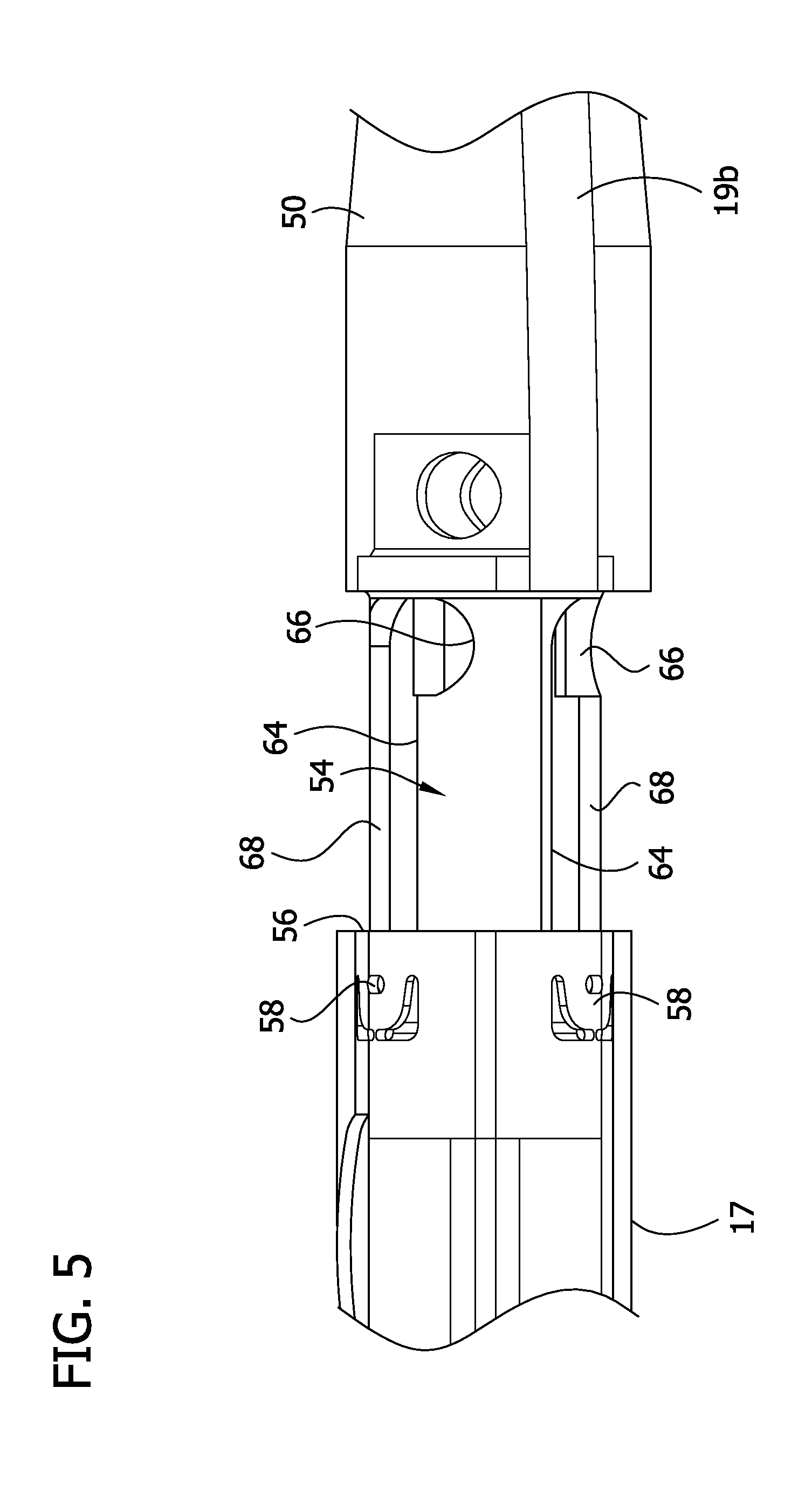
FIG. 5 is another illustration of the distal end of the catheter showing the catheter in the open position and with the tissue containment chamber and distal end shown as transparent showing internal detail;
FIG. 6 is an illustration of a distal end of a catheter of another embodiment showing a distal tip component and closure component separated from a tissue-containment chamber and with the tissue containment chamber and distal tip component shown as transparent showing internal detail;
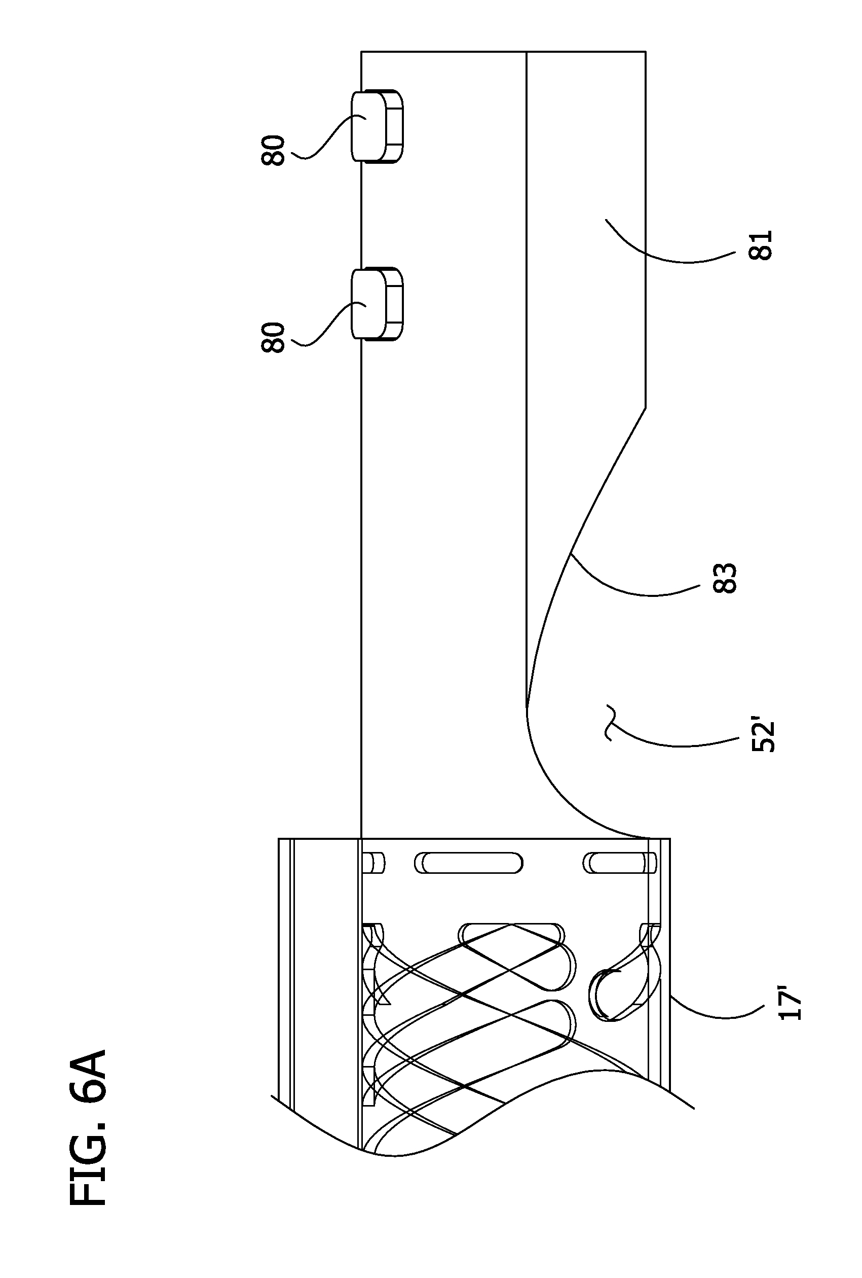
FIG. 6A is an enlarged fragmentary view of the tissue-containment chamber in FIG. 6;
FIG. 6B is an enlarged fragmentary view of the closure component in FIG. 6 with portions removed showing interior detail;
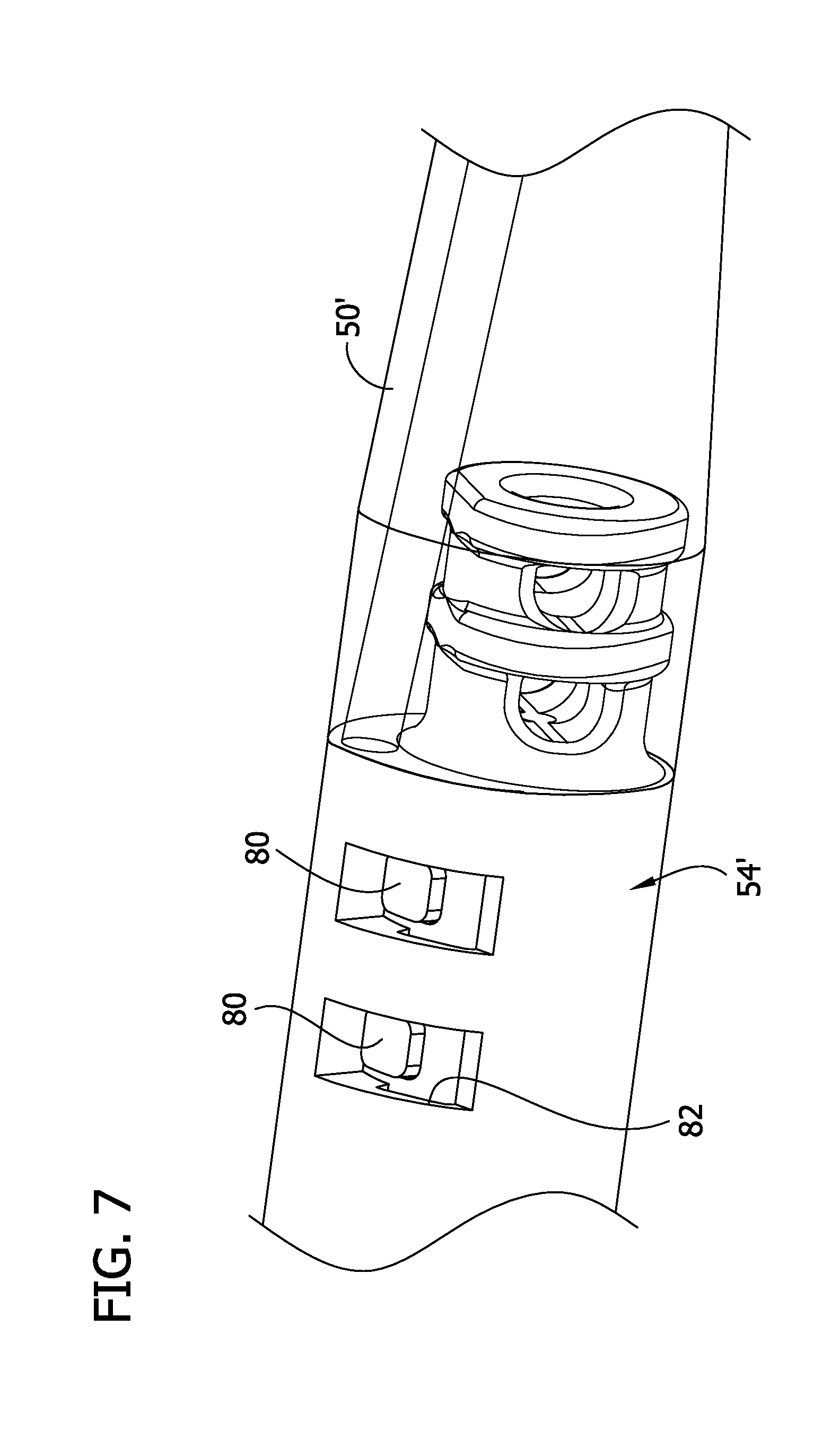
FIG. 7 is an illustration of the catheter of FIG. 6 showing the catheter in a closed and locked position;
FIG. 7A is another illustration of the catheter of FIG. 6 showing the catheter in a closed and locked position;
FIG. 8 is an illustration of the catheter of FIG. 6 showing the catheter in a closed position and unlocked;
FIG. 8A is another illustration of the catheter of FIG. 6 showing the catheter in a closed position and unlocked;
FIG. 9 is an illustration of the catheter of FIG. 6 showing the catheter in an open position;
FIG. 10 is another illustration of the catheter of FIG. 6 showing the catheter in the open position;
FIG. 11 is another illustration of the catheter of FIG. 6 showing a stop;
FIG. 11A is an enlarged fragmentary view of catheter of FIG. 11;
FIG. 12 is an illustration of a distal end of a catheter of another embodiment showing the catheter is a closed position and with a tissue containment chamber and distal end shown as transparent showing internal detail;
FIG. 13 is an illustration of the distal end of the catheter of FIG. 12 showing the catheter is an intermediate position;
FIG. 14 is an illustration of the distal end of the catheter of FIG. 12 showing the catheter is an open position; and
FIG. 15 is an enlarged fragmentary view of a distal end of a tissue-containment chamber of the catheter of FIG. 12.
Corresponding reference characters indicate corresponding parts throughout the drawings.
DETAILED DESCRIPTION OF THE DISCLOSURE
Embodiments of a tissue-removing catheter having moveable distal portions for removing material stored in the catheter are disclosed. In particular, the illustrated catheter embodiments are particularly suitable for removing (i.e., excising) plaque tissue from a blood vessel (e.g., peripheral arterial or peripheral venous wall). Features of the disclosed embodiments, however, may also be suitable for treating chronic total occlusion (CTO) of blood vessels, particularly peripheral arteries, and stenoses of other body lumens and other hyperplastic and neoplastic conditions in other body lumens, such as the ureter, the biliary duct, respiratory channels, the pancreatic duct, the lymphatic duct, and the like. Neoplastic cell growth will often occur as a result of a tumor surrounding and intruding into a body lumen. Removal of such material can thus be beneficial to maintain patency of the body lumen. While the remaining discussion is directed toward catheters for removing tissue from, and penetrating occlusions in, blood vessels (e.g., atheromatous or thrombotic occlusive material in an artery, or other occlusions in veins), it will be appreciated that the teachings of the present disclosure apply equally to other types of tissue-removing catheters, including, but not limited to, catheters for penetrating and/or removing tissue from a variety of occlusive, stenotic, or hyperplastic material in a variety of body lumens.
Referring to FIG. 1, a tissue-removing catheter, in accordance with one or more embodiments of the present disclosure, is generally indicated at reference numeral 10. The catheter 10 comprises an elongate catheter body, generally indicated at 12, having opposite proximal and distal ends 12a, 12b, respectively, and a longitudinal axis extending between the proximal and distal ends. The catheter body 12 can have other configurations without departing from the scope of this disclosure. A handle or control unit, generally indicated at 14, is disposed on the proximal end 12a of the catheter body 12 for manipulation by a user. A tissue-removing element, generally indicated at 16, generally adjacent the distal end 12b of the catheter body 12, is configured to remove (e.g., cut) tissue from the body lumen and direct the removed tissue into a lumen 15 (FIG. 2) of a tissue-containment chamber 17 adjacent the distal end of the catheter body. The catheter 10 is advanced over a guide wire 18 which extends through a guide wire lumen 19 on the catheter (FIG. 3). The guide wire 18 facilitates manipulation of the catheter 10 through the subject's blood vessels.
Referring to FIG. 2, in the illustrated embodiment, the tissue-removing element 16 comprises a rotatable cutting element that is rotatable about a rotation axis RA1 for cutting tissue. The illustrated cutting element 16 has a cutting edge 23 facing distally, although in other embodiments the cutting edge may face proximally, and a cup-shaped surface 20 for directing removed tissue distally into the tissue-containment chamber 17 of the catheter body 12. In other embodiments, the tissue-removing element may have other configurations for cutting tissue, or may be configured to remove tissue in other ways. For example, the tissue-removing element may be configured to ablate tissue, or abrade tissue, or otherwise remove tissue from the body lumen. Moreover, the tissue-removing element may not be rotatable relative to the catheter body.
Referring still to FIG. 2, a tissue-removing driveshaft 26 is operatively connected to a stem 28 of the tissue-removing element 16 (e.g., fixedly secured thereto) for imparting rotation to the tissue-removing element. The tissue-removing driveshaft 26 (e.g., a coiled driveshaft) extends through the catheter body 12 and is operatively connectable to an electric driveshaft motor 30 (FIG. 1), or other prime mover, in the handle 14 for driving rotation of the driveshaft, and in turn, driving rotation of the tissue-removing element 16, relative to the catheter body. The driveshaft motor 30 is electrically connected to a power source 21 in the handle 14 (FIG. 1). In the illustrated embodiment, the driveshaft 26 is movable longitudinally within the catheter body 12 to impart longitudinal movement of the tissue-removing element 16 relative to the catheter body. Longitudinal movement of the tissue-removing element 16 actuates deployment and storage of the tissue-removing element relative to a tissue-removing housing 34, which is connected to the distal end 12b of the body 12. A distal portion of the housing 34 forms the tissue container 17, although the housing and the tissue collection chamber may be formed separately.
The tissue-removing element 16 is movable between a stored position (not shown) and a deployed position (FIGS. 1 and 2). In the stored position, the tissue-removing element 16 is received in the housing 34 and is not exposed through a window or side opening 38 of the housing. To deploy the tissue-removing element 16, the driveshaft 26 is moved proximally relative to the catheter body 12, such as by moving a lever or other actuator 40 (FIG. 1) on the handle 14 that is operatively connected to the driveshaft, to impart proximal movement of the tissue-removing element 16 relative to the housing 34. Referring to FIG. 2, as the tissue-removing element 16 moves proximally, the tissue-removing element, which acts as a cam, engages and moves longitudinally along an internal cam follower 42 of the housing 34, causing the housing to pivot or deflect relative to the body 12 and the tissue-removing element to extend partially out of the window 38. To return the tissue-removing element 16 to its stored, non-deployed position, the driveshaft 26 is moved distally, such as by moving the actuator 40 distally, to impart distal movement of the tissue-removing element 16 along the cam follower 42. Distal movement of the tissue-removing element 16 causes the housing 34 to pivot or deflect back relative to the body 12 so that the tissue-removing element is received in the housing 34 and does not extend outside the window 38. When the tissue-removing element 16 is in its stored position, the driveshaft motor 30 is deactivated (i.e., turned off). It is understood that a catheter 10 constructed according to the principles of the present disclosure may not include a deployment mechanism (e.g., the tissue-removing element or other functional element may always be deployed or may remain within the catheter body).
The material cut by the tissue-removing element 16 is directed through the window 38 and into the lumen 15 of the tissue-containment chamber 17 located distal to the window. The catheter 10 may be passed through the vessel a number of times with the material from each pass being stored in the tissue-containment chamber 17. When the tissue-containment chamber 17 is full, the catheter 10 is removed from the patient and the tissue-containment chamber may be cleaned for subsequent use as described below.
Referring now to FIGS. 3 and 4, a distal tip component 50 is disposed at the distal end of the tissue-containment chamber 17. The distal tip component 50 may be formed from a flexible material such that the tip component is generally atraumatic. The tissue-containment chamber 17 defines a tissue-removing opening 52 to facilitate removal of the material from the chamber. The tissue-removing opening 52 is selectively opened and closed by movement of a closure component, generally indicated at 54. The closure component 54 has a proximal end received in a distal opening 56 of the tissue-containment chamber 17, and a distal end attached to a proximal end of the distal tip component 50. Movement of the distal tip component 50 causes conjoint movement of the closure component 54 in the lumen 15 of the tissue containment chamber 17. In particular, the distal tip component 50 and closure component 54 are slidable along a longitudinal axis A2 of the tissue-containment chamber 17 to move between a closed position of FIG. 3, where the tissue-removing opening 52 is blocked by the closure component (i.e., closed), and an open position of FIG. 4, where the tissue-removing opening is unblocked (i.e., open). For reasons explained below, the tissue-containment chamber 17 has a plurality of tabs 58 (broadly, one or more bosses) disposed near a distal end of the tissue-containment chamber. The tabs 58 extend into the lumen 15 of the tissue-containment chamber 17. In the illustrated embodiment, the tabs 58 are punched from the tissue-containment chamber 17. The tabs 58 can have other configurations and can be formed in other ways without departing from the scope of the disclosure. For instance the tabs 58 can be formed separately from the tissue-containment chamber and suitably attached to the tissue-containment chamber 17.
In the illustrated embodiment, as shown in FIG. 4, the closure component 54 includes an elongate body having a scoop portion 60 at its proximal end that is curved to direct material out of the tissue-removing opening 52 when in the open position. As shown in FIG. 3, a plug portion 62 of the body blocks the tissue-removing opening 52 in the tissue-containment chamber 17 when the closure component 54 is in the closed position. The closure component 54 may have other constructions without departing from various aspects of the present disclosure. For example, the scoop portion 60 of the closure component 54 could have a conical shape, or other shapes, with multiple openings to allow expungement in multiple directions. Moreover, the scoop portion 60 may be omitted in other embodiments.
The closure component 54 includes a plurality of L-shaped slots 64 (broadly, one or more grooves) each having a circumferentially extending portion 66, an axially extending portion 68, and a juncture connecting the axially extending portion to the circumferentially extending portion. Only one L-shaped slot 64 is visible in FIGS. 3 and 4, and two L-shaped slots are visible in FIG. 5. As shown in FIGS. 4 and 5, the circumferentially extending portion 66 of each slot 64 is disposed near the distal end of the closure component 54, and the axially extending portion 68 extends from the juncture toward the proximal end of the closure component. In one embodiment, each of the circumferentially extending portions 66 subtends about 30.degree. about a circumference of the closure component 54. In another embodiment, each of the circumferentially extending portions 66 subtends between about 15.degree. and about 45.degree. about the circumference of the closure component 54. The tabs 58 of the tissue-containment chamber 17 are retained in respective L-shaped slots 64 to form a boss-and-groove connection. The tabs 58 are moveable within the slots 64 to permit movement of the closure component 54 relative to the tissue-containment chamber 17 between the open and closed positions. The slots 64 may have other configurations than L-shaped. For instance, slots (not shown) may be U-shaped to allow circumferential movement of the tabs in the slots in both clockwise and counterclockwise directions prior to sliding the tabs axially in one of the legs of the U-shaped slots. Alternatively, the slots (not shown) may be J-shaped.
To move the closure component 54 from the closed position (FIG. 3) to the open position (FIG. 4), the distal tip component 50 may be grasped and rotated counterclockwise (as viewed from the distal end of the tip 50) so the tabs track in the circumferentially extending portions 66 and into the junctures between the circumferentially extending portions and the longitudinally extending portions 68. Rotating the closure component 54 in this manner generally axially aligns the scoop portion 60 of the closure component with the tissue-removing opening 52 in the tissue-containment chamber 17. The distal tip component 50 may then be moved in an axial direction (e.g., distally) to slide the closure component 54 axially (e.g., distally) so that the tabs 58 track along the axially extending portions 68 of the slots 64. The axial movement of the distal tip component 50 may be aided by a spring (not shown) disposed between the tissue-containment chamber 17 and the distal tip component 50. The sliding engagements between the slots 64 and tabs 58 also prevent the distal tip component 50 and closure component 54 from being separated from the tissue-containment chamber 17. The distal tip component 50 is moved until the scoop portion 60 of the closure component 54 is positioned in registration with the tissue-removing opening 52 in the tissue-containment chamber 17, thereby opening the tissue-removing opening. In this position, the tabs 58 engage the end (e.g., proximal end) of the axially extending portions 68 of the slots 64 to inhibit further axial movement of the closure component 54. Once the tissue-removing opening 52 has been opened, material in the tissue-containment chamber 17 may be removed in a number of different ways. The material may simply be discarded in the appropriate manner after removal from the catheter 10. Alternatively, the material may also be saved in a storage container (not shown). It will be understood that the tabs 58 may be on the closure component 54 and the slots 64 may be in the tissue-containment chamber 17 without departing from the scope of the disclosure. Also, any number of tabs 58 and slots 64 can be incorporated without departing from the scope of the disclosure.
The guide wire lumen 19 extends along the catheter 10 and includes a proximal section 19a extending along (e.g., mounted on) the tissue-containment chamber 17 and a distal section 19b extending along (e.g., mounted on) the distal tip component 50. The proximal and distal sections 19a, 19b of the guide wire lumen 19 are spaced apart by a gap or void 70. The proximal section 19a of the guide wire lumen 19 is aligned with the distal section 19b when the closure component 54 is in the closed position of FIG. 3. In this manner, when the closure component 54 is in the closed position and the guide wire 18 is fully inserted into the guide wire lumen 19, the guide wire 18 inhibits unintentional rotation of the closure component, thereby maintaining or locking the closure component in the closed position. The guide wire 18 may lock the closure component in other suitable ways to inhibit unintentional opening of the tissue-removing opening 52. For example, the catheter may include a biased locking element (not shown).
The construction of the tissue-containment chamber 17 and closure component 54 permit rotation and axial sliding of the distal tip component 50 to expose the tissue-removing opening 52 without having to remove the guide wire 18 from either of the sections 19a, 19b of the guide wire lumen 19. When the rotational force is applied to the distal tip component 50, the closure component 54 rotates and the tabs 58 on the tissue containment chamber 17 track in the circumferentially extending portions 68 of the slots 64 in the closure component and into the juncture. Rotating the distal tip component 50 applies bending stress to the guide wire 18 because proximal and distal portions 19a, 19b of the guide wire lumen 19 become unaligned. The guide wire resiliently bends under the applied bending stress and stores a return force biasing the closure component 54 to the closed position. As a result, the return force in the guide wire 18 can automatically move the closure component 54 to the closed position when the tabs 58 are located at the junctures and the rotational force applied by the user is removed. However, if the rotational force is maintained by the user, the distal tip component 50 can then be pulled distally, and/or urged distally by a stored energy component (e.g., spring) to move the closure component 54 distally and track the tabs 58 on the tissue-containment chamber 17 in the axially extending portions 68 of the slots 64 in the closure component 54 to open the tissue-removing opening 52. With the tabs 58 received in the axially extending portions 68 of the slots 64, the return force being generated by the guide wire 18 acts to hold the closure component 54 in the open position. This reduces the chance of the closure component 54 sliding back into the closed position. When the catheter 10 is removed from the patient, the guide wire 18 remains in the guide wire lumen 19. By leaving the guide wire 18 in the guide wire lumen 19, cleaning the catheter 10 is more efficient than having to remove the guide wire before cleaning and then reinsert the guide wire into the guide wire lumen after cleaning.
When it is desired to close the tissue-removing opening 52, the distal tip component 50 is pushed proximally to track the tabs 58 into the junctures between the axially extending portions 68 and the circumferentially extending portions 66 of the slots 64. The return force of the guide wire 18 may aid in or automatically move the closure component 54 back to the closed position, thereby closing the tissue-removing opening 52. Additionally, if the distal tip component 50 and closure component 54 are not moved to the closed position before the catheter 10 is used, a distal to proximal force acting on the distal tip component when the catheter is inserted into a hemostasis valve can move the closure component axially (e.g., proximally) to track the tabs 58 into the junctures so that the closure component moves to the closed position under the return force of the guide wire 18.
Additionally or alternatively, a snapping mechanism (not shown) may lock the distal tip component 50 and closure component 54 in the closed or open position. A small axial force may be necessary to unseat the snapping mechanism to move the distal tip component 50 and closure component 54 relative to the tissue-containment chamber 17. The snapping mechanism may comprise a metal to metal or metal interference fit or a metal to plastic interference fit to lock the distal tip component 50 and closure component 54 in the closed or open position.
Referring to FIG. 6-6B, a catheter 10' of another embodiment includes protrusions 80 (broadly, one or more bosses) formed on an extension member 81 of a tissue-containment chamber 17' near a distal end of the chamber, and a channel 82 (broadly, one or more grooves; FIG. 6B) formed in an interior surface of a closure component 54'. In the illustrated embodiment, the closure component 54' is slidably received on the extension member 81 such that the closure component functions as a sleeve. The extension member 81 defines a tissue-removing opening 52' of the tissue-containment chamber 17', which is generally in the form of a side opening. The tissue-removing opening 52' may be defined by a scoop portion of the extension member 81. A pair of protrusions 80 are axially aligned and spaced along the extension member 81 of the tissue-containment chamber 17'. The channel 82 includes a pair of circumferentially extending portions 84 axially aligned and spaced along the interior surface of the closure component 54', and an axially extending portion 86 extending between ends of the circumferentially extending portions 84 and proximally from the circumferentially extending portions. The protrusions 80 on the tissue-containment chamber 17' are retained in channel 82 to form a boss-and-groove connection. The protrusions 80 track within the channel 82 to guide the closure component 54' relative to the tissue-containment chamber 17' between open and closed positions.
To move the closure component 54' from a closed and locked position (FIGS. 7 and 7A), in which the closure component covers the tissue-removing opening 52', to an open position (FIGS. 9 and 10), a distal tip component 50' may be grasped and rotated counterclockwise (as viewed from the distal end of the tip component) to track each protrusion 80 in a respective circumferentially extending portion 84 of the channel 82 to the juncture between the circumferentially extending portion and the axially extending portion 86 of the channel, as shown in FIG. 8. As explained in the previous embodiment and shown in FIG. 8A, rotating the closure component 54' in this manner bends a guide wire 18' in the guide wire lumen 19, which places a return load on the guide wire for returning the catheter 10' to the closed position.
From the rotational position shown in FIGS. 8 and 8A, the distal tip component 50' can then be moved in an axial direction to slide the protrusions 80 along the axially extending portion 86 of the channel 82. The distal tip component 50' is pulled until the closure component 54' no longer covers the tissue-removing opening 52' of the tissue-containment chamber 17' thereby opening the tissue-removing opening, as shown in FIGS. 9 and 10. It will be understood that the protrusions 80 may be on the closure component 54' and the channel 82 may be formed in the tissue-containment chamber 17' without departing from the scope of the disclosure.
Referring to FIGS. 10, 11 and 11A, a stop 90 may be disposed near a distal end of the tissue-containment chamber 17' to limit movement of a closure component 54' distally away from the tissue-containment chamber. In the illustrated embodiment, the stop 90 comprises a tab attached to an outer surface of the tissue-containment chamber 17', more specifically the extension member 81 of the tissue-containment chamber. The tab 90 engages a proximal end of a slot 92 formed in the closure component 54' to limit further movement of the closure component. The stop 90 may engage some other portion of the catheter to limit movement of the closure component without departing from the scope of the disclosure.
Additionally or alternatively, tabs (not shown) can be machined into the closure component, and a slot (e.g., laser cut) may be formed in the tissue-containment chamber.
Additionally or alternatively, multiple laser cut tabs may be formed on the distal end of a tissue-containment chamber. A most proximal tab can lock a machined feature on a closure component until a distal tip component is pushed proximally against a gasket (not shown) and then rotated and pulled distally as described in previous embodiments. Movement of the distal tip component and closure component in the distal direction is stopped by a distal most tab on the tissue-containment chamber. Thus, the locking mechanism is built into the tabs rather than using the return force created between the guide wire and sections of the guide wire lumen when the closure component is rotated.
Referring to FIGS. 12-14, a catheter of another embodiment is illustrated generally at 10''. A tissue-removing opening 52'' (FIG. 14) in a tissue-containment chamber 17'' of the catheter 10'' allows removal of material stored in the chamber. The catheter 10'' includes a closure component, generally indicated at 54'', having a proximal end received in the tissue-removing opening 52'' of the tissue-containment chamber 17'' and a distal end attached to a proximal end of a distal tip component 50'' such that movement of the distal tip component causes conjoint movement of the closure component. The distal tip component 50'' and closure component 54'' are movable to selectively open and close the tissue-removing opening 52'' in the tissue-containment chamber 17''. In the illustrated embodiment, the tissue-removing opening 52'' is defined by a distal opening extending axially through the distal end of the tissue-containment chamber 17'. The tissue-removing opening 52'' may be created in any other manner without departing from various aspects of the present disclosure.
The tissue-containment chamber 17'' includes a plurality of catches, generally indicated at 99 (only one is shown), near the distal end of the tissue-containment chamber. Each catch 99 is generally in the form of a deflectable cantilever snap-fit arm defining an opening 100 therein. The openings 100 are spaced circumferentially around the tissue-containment chamber 17'' and each opening is spaced from a distal edge of the tissue-containment chamber. A plurality of narrow slits 102 are formed in the distal end to the tissue-containment chamber 17'' and spaced circumferentially around the tissue-containment chamber to form the catches 99. Each slit 102 extends from the distal edge of the tissue-containment chamber 17'' to a widened base 104. A pair of slits 102 is associated with each catch 99. As illustrated, each pair of slits 100 is disposed on opposite circumferential sides of a catch 100. Each catch 99 is resiliently deflectable or flexible radially outward when engaged by the closure component 54'' as will be explained in greater detail below.
The closure component 54'' includes a plurality of hooks 108 disposed adjacent a proximal end of the closure component. In the illustrated embodiment, the hooks 108 are connected to one another and are part of a single hook base unit 109. When the proximal end of the closure component 54'' is fully received in the distal end of the tissue-containment chamber 17'', the hooks 108 are captured within the openings 100 of the respective catches 99 to secure the distal tip component 50'' and closure component 54'' to the tissue-containment chamber 17''. Referring to FIG. 15, each hook 108 includes a first ramp surface 110, a second ramp surface 112, and a third ramp surface 114. The first ramp surface 110 extends upwards from a leading edge of the ramp 108 at an angle to the second ramp surface 112. The second ramp surface extends from the first ramp surface 110 to the third ramp surface 114 generally along a plane parallel to an outer surface of the tissue-containment chamber 17''. The third ramp surface 114 extends downward from the second ramp surface 112 toward a trailing edge of the ramp 108. As explained below, the structure of the hooks 108 allows for releasable locking of the closure component 54'' in the tissue-containment chamber 17''.
A first tube lumen 116 is disposed on the tissue-containment chamber 17''. The first tube lumen 116 extends from a distal edge of the tissue-containment chamber 17'' to a location proximal to the distal edge of the tissue-containment chamber. A first tube 118 is fixedly disposed in first the tube lumen 116 generally at a distal end of the first tube lumen. A second tube lumen 120 is disposed on the closure component 54''. The second tube lumen 120 extends from a proximal edge of the closure component 54'' to a location distal to the proximal edge of the closure component. A second tube 122 is fixedly disposed in the second tube lumen 120 and extends into the first tube lumen 116 in the tissue-containment chamber 17'' and through the first tube 118 in the first tube lumen. The second tube 122 comprises a first diameter portion 124 sized to be received in the first tube 118 and slide within the first tube, and a second diameter portion 126 wider than the first diameter portion. The second diameter portion 126 is sized to abut the first tube 118 when the second hollow tube 122 is slid distally relative to the first tube. This configuration limits movement of the distal tip component 50'' and closure component 54'' away from the tissue-containment chamber 17'' and allows rotation of the distal tip component and closure component relative to the tissue-containment chamber as will be explained in greater detail below. The tubes 118, 122 may be fixedly disposed in the lumens 116, 120 by any suitable means such as welding, brazing or adhesive. Moreover, the lumens 116, 120 may be omitted without departing from the scope of the present invention. The first and second diameter portions 124, 126 of the second tube 122 may be formed separately and attached to each other by any suitable means such as welding, brazing, or adhesive. Alternatively, the first and second diameter portion 124, 126 can be formed integrally. The first and second tubes 118, 122 are aligned with the proximal and distal guide wire lumen portions 19a, 19b, respectively, to partially define the guide wire lumen 19''. A guide wire (not shown) is insertable through the guide wire lumen 19'', including the first and second tubes 118, 122, respectively.
In the closed position, the closure component 54'' is received in the tissue-removing opening 52'' of the tissue-containment chamber 17'' and the hooks 108 on the closure component are captured in the openings 100 of the catches 99 to secure the distal tip component 50'' and closure component to the tissue-containment chamber. To open the tissue-removing opening 52'', an axial pulling force in a distal direction is applied to the distal tip component 50''. A sufficient amount of force causes the closure component 54'' to move distally and an inner surface of the catches 99 to ride up the first ramp surfaces 110 of the hooks 108. As the catches 99 ride up the first hook surfaces 110, the catches resiliently deflect outward and away from the hooks 108 providing clearance for the closure component 54'' to continue its distal movement. Continued distal movement of the closure component 54'' will cause the inner surfaces of the catches 99 to reach the second ramp surfaces 112 and then ride down the third ramp surfaces 114 freeing the hooks from the openings 100. Once the hooks 108 are free from the openings 100 the closure component 54'' and hooks 108 can be pulled completely out of the tissue-containment chamber 17''. Distal movement of the distal tip component 50'' and closure component 54'' is stopped when the second diameter portion 126 of the second hollow tube 122 engages the first hollow tube 118.
After removing the closure component 54'' from the tissue-containment chamber 17'', the distal tip component 50'' and closure component 54'' are rotated, whereby the second tube 122 rotates about an axis of the first tube 118, until the tissue-removing open is open. For instance, the distal tip component 50'' and closure component 54'' can be rotated about 180 degrees about the first tube 118 to open the tissue-removing opening 52''. Other degrees of rotation are also envisioned. Thus, the distal tip component 50'' and closure component 54'' rotate about an axis that is radially offset from a longitudinal axis of the tissue-containment chamber 17''. In the illustrated embodiment, the rotation is around an axis coincident with at least a portion of the guide wire lumen 19''. As a result, the guide wire (not shown) and guide wire lumen 19'' are not placed in shear or deformed by rotation of the distal tip component 50'' and closure component 54''.
To close the tissue-removing opening 52'', the distal tip component 50'' and closure component 54'' are rotated back into alignment with the tissue-removing opening and pushed proximally until the hooks 108 on the closure component are captured by the openings 100 of the catches 99, thereby locking the distal tip component 50'' and closure component to the tissue-containment chamber 17''. As the closure component 54'' is pushed proximally into the tissue-containment chamber 17'', the third ramp surfaces 114 of the hooks 108 engage interior surfaces of the catches 99. A sufficient amount of force causes the closure component 54'' to move proximally and the inner surfaces of the catches 99 to ride up the third ramp surfaces 114 of the ramps 108. As the catches 99 ride up the third ramp surfaces 114, the catches resiliently deflect outward and away from the hooks 108 providing clearance for the closure component 54'' to continue its proximal movement. Continued proximal movement of the closure component 54'' will cause the inner surfaces of the catches 99 to reach the second ramp surfaces 112 and then ride down the first ramp surfaces 110 capturing the hooks 108 in the openings 100.
The catheter 10'' of this embodiment is also capable of being cleaned without the use of a separate flush tool. By adjusting a packing stroke length of the catheter 10'' it is possible to push any tissue in the tissue-containment chamber 17'' out of the catheter 10'' by pushing the tissue distally in the tissue-containment chamber. In this embodiment, a cutter driver (not shown) may operate in at least two settings for controlling the packing stroke of the cutter. For instance, the cutter driver may operate in a first setting for packing tissue while the tissue-removing opening 52'' is closed and a second setting for expelling tissue from the catheter 10'' when the tissue-removing opening is open. Because the tissue-removing opening 52'' is aligned with the longitudinal axis of the tissue-containment chamber 17'', the tissue can be removed from the catheter 10'' by this operation alone. To further facilitate removing tissue from the catheter 10'' in this manner, a distal end of the tissue-containment chamber 17'' may have a tapered inner diameter to reduce friction between the packed tissue and the tissue-containment chamber.
Having described embodiments of the invention in detail, it will be apparent that modifications and variations are possible without departing from the scope of the invention defined in the appended claims.
When introducing elements of the present invention or the preferred embodiment(s) thereof, the articles "a", "an", "the" and "said" are intended to mean that there are one or more of the elements. The terms "comprising", "including" and "having" are intended to be inclusive and mean that there may be additional elements other than the listed elements.
As various changes could be made in the above constructions, products, and methods without departing from the scope of the invention, it is intended that all matter contained in the above description and shown in the accompanying drawings shall be interpreted as illustrative and not in a limiting sense.
* * * * *
References
D00000
D00001
D00002
D00003
D00004
D00005
D00006
D00007
D00008
D00009
D00010
D00011
D00012

D00013

D00014

D00015

D00016

D00017

D00018

D00019

D00020

XML
uspto.report is an independent third-party trademark research tool that is not affiliated, endorsed, or sponsored by the United States Patent and Trademark Office (USPTO) or any other governmental organization. The information provided by uspto.report is based on publicly available data at the time of writing and is intended for informational purposes only.
While we strive to provide accurate and up-to-date information, we do not guarantee the accuracy, completeness, reliability, or suitability of the information displayed on this site. The use of this site is at your own risk. Any reliance you place on such information is therefore strictly at your own risk.
All official trademark data, including owner information, should be verified by visiting the official USPTO website at www.uspto.gov. This site is not intended to replace professional legal advice and should not be used as a substitute for consulting with a legal professional who is knowledgeable about trademark law.