Multi-generator applications using variable speed and solid state generators for efficiency and frequency stabilization
Taimela , et al.
U.S. patent number 10,289,080 [Application Number 14/258,649] was granted by the patent office on 2019-05-14 for multi-generator applications using variable speed and solid state generators for efficiency and frequency stabilization. This patent grant is currently assigned to Flexgen Power Systems, Inc.. The grantee listed for this patent is FLEXGEN POWER SYSTEMS, INC.. Invention is credited to Robert William Johnson, Jr., Tony Olivo, Pasi Taimela.


| United States Patent | 10,289,080 |
| Taimela , et al. | May 14, 2019 |
Multi-generator applications using variable speed and solid state generators for efficiency and frequency stabilization
Abstract
A system includes at least one variable speed generator system configured to provide power to a load bus and at least one fixed speed generator configured to provide power to the load bus. The system also includes a solid state generator (SSG) system including at least one energy storage device and a converter coupled to the at least one energy storage device and configured to transfer power between the at least one energy storage device and the load bus. The system further includes a control system configured to control the at least one variable speed generator system, the at least one fixed speed generator and the SSG system responsive to changes in a load on the load bus.
| Inventors: | Taimela; Pasi (Wake Forest, NC), Olivo; Tony (Raleigh, NC), Johnson, Jr.; Robert William (Raleigh, NC) | ||||||||||
|---|---|---|---|---|---|---|---|---|---|---|---|
| Applicant: |
|
||||||||||
| Assignee: | Flexgen Power Systems, Inc.
(Durham, NC) |
||||||||||
| Family ID: | 51729624 | ||||||||||
| Appl. No.: | 14/258,649 | ||||||||||
| Filed: | April 22, 2014 |
Prior Publication Data
| Document Identifier | Publication Date | |
|---|---|---|
| US 20140316593 A1 | Oct 23, 2014 | |
Related U.S. Patent Documents
| Application Number | Filing Date | Patent Number | Issue Date | ||
|---|---|---|---|---|---|
| 13875603 | May 2, 2013 | 9312699 | |||
| 61814987 | Apr 23, 2013 | ||||
| 61771417 | Mar 1, 2013 | ||||
| 61712533 | Oct 11, 2012 | ||||
| Current U.S. Class: | 1/1 |
| Current CPC Class: | H02J 3/28 (20130101); H02J 3/381 (20130101); H02J 3/24 (20130101); G05B 15/02 (20130101); Y02E 40/70 (20130101); H02J 2310/10 (20200101); Y10T 307/516 (20150401); H02J 2300/10 (20200101); H02J 3/30 (20130101); H02J 3/32 (20130101); Y02E 40/10 (20130101); Y04S 10/12 (20130101) |
| Current International Class: | G05B 15/02 (20060101); H02J 3/24 (20060101); H02J 3/28 (20060101); H02J 3/38 (20060101); H02J 3/30 (20060101); H02J 3/32 (20060101) |
| Field of Search: | ;307/66 |
References Cited [Referenced By]
U.S. Patent Documents
| 4992920 | February 1991 | Davis |
| 5563802 | October 1996 | Plahn |
| 5907192 | May 1999 | Lyons et al. |
| 5929538 | July 1999 | O'Sullivan et al. |
| 6038118 | March 2000 | Guerra |
| 6104102 | August 2000 | Tsuji et al. |
| 6128204 | October 2000 | Munro et al. |
| 6175217 | January 2001 | Da Ponte et al. |
| 6252753 | June 2001 | Bhargava |
| 6870279 | March 2005 | Gilbreth et al. |
| 6879053 | April 2005 | Weiches et al. |
| 6958550 | October 2005 | Gilbreth et al. |
| 6969922 | November 2005 | Welches et al. |
| 7002260 | February 2006 | Stahlkopf |
| 7116010 | October 2006 | Lasseter et al. |
| 7184903 | February 2007 | Williams et al. |
| 7391126 | June 2008 | Liu et al. |
| 7474016 | January 2009 | Wang et al. |
| 7476987 | January 2009 | Chang |
| 7514808 | April 2009 | Wobben |
| 7560906 | July 2009 | Liu et al. |
| 7612466 | November 2009 | Skutt |
| 7675187 | March 2010 | Woods et al. |
| 7680562 | March 2010 | Delmerico et al. |
| 7701087 | April 2010 | Eckroad et al. |
| 7781902 | August 2010 | Cerney et al. |
| 7787272 | August 2010 | Lasseter et al. |
| 7834479 | November 2010 | Capp et al. |
| 7855467 | December 2010 | Kawazoe et al. |
| 7906862 | March 2011 | Donnelly et al. |
| 7969030 | June 2011 | Woods et al. |
| 8022572 | September 2011 | Vyas et al. |
| 8080898 | December 2011 | Fukuhara |
| 8099198 | January 2012 | Gurin |
| 8164217 | April 2012 | Miller |
| 8222756 | July 2012 | Koeneman et al. |
| 8227929 | July 2012 | Burra et al. |
| 8315745 | November 2012 | Creed |
| 8338987 | December 2012 | O'Brien et al. |
| 8452688 | May 2013 | Sharplin et al. |
| 8492913 | July 2013 | Koeneman et al. |
| 8532834 | September 2013 | Delong et al. |
| 8558510 | October 2013 | Moon |
| 8688281 | April 2014 | Viassolo et al. |
| 8751036 | June 2014 | Darden, II et al. |
| 8766474 | July 2014 | Carralero et al. |
| 8810066 | August 2014 | Moon |
| 8829698 | September 2014 | Koeneman et al. |
| 8831788 | September 2014 | Flynn et al. |
| 8849469 | September 2014 | Belady et al. |
| 8866334 | October 2014 | Donnelly et al. |
| 8922056 | December 2014 | Thisted |
| 8922062 | December 2014 | Johnson et al. |
| 8938323 | January 2015 | Lee |
| 8946916 | February 2015 | Tarnowski |
| 8946929 | February 2015 | Singh et al. |
| 8975767 | March 2015 | Algrain |
| 9026259 | May 2015 | Zadeh et al. |
| 9026260 | May 2015 | Thornley et al. |
| 9042141 | May 2015 | Yu et al. |
| 2002/0190525 | December 2002 | Worden et al. |
| 2002/0198648 | December 2002 | Gilbreth et al. |
| 2003/0047209 | March 2003 | Yanai et al. |
| 2004/0051387 | March 2004 | Lasseter et al. |
| 2004/0084965 | May 2004 | Welches |
| 2004/0245783 | December 2004 | Gilbreth et al. |
| 2005/0012395 | January 2005 | Eckroad et al. |
| 2005/0077881 | April 2005 | Capp |
| 2005/0154499 | July 2005 | Aldridge et al. |
| 2005/0200133 | September 2005 | Wobben |
| 2007/0182158 | August 2007 | Cerney et al. |
| 2007/0228836 | October 2007 | Teichmann |
| 2007/0267871 | November 2007 | Gregory |
| 2008/0088183 | April 2008 | Eckroad et al. |
| 2008/0203734 | August 2008 | Grimes et al. |
| 2008/0211230 | September 2008 | Gurin |
| 2008/0278000 | November 2008 | Capp et al. |
| 2009/0086520 | April 2009 | Nishimura |
| 2009/0140576 | June 2009 | Yu et al. |
| 2009/0189456 | July 2009 | Skutt |
| 2009/0195074 | August 2009 | Buiel |
| 2009/0312885 | December 2009 | Buiel |
| 2010/0008119 | January 2010 | O'Brien et al. |
| 2010/0138066 | June 2010 | Kong |
| 2010/0264739 | October 2010 | Errington |
| 2010/0270864 | October 2010 | Vyas |
| 2010/0327800 | December 2010 | Reineccius |
| 2011/0060474 | March 2011 | Schmiegel et al. |
| 2011/0062708 | March 2011 | Prochaska et al. |
| 2011/0068631 | March 2011 | Roscoe |
| 2011/0080044 | April 2011 | Schmiegel |
| 2011/0115295 | May 2011 | Moon et al. |
| 2011/0118894 | May 2011 | Reineccius et al. |
| 2011/0133558 | June 2011 | Park |
| 2011/0140520 | June 2011 | Lee |
| 2011/0140648 | June 2011 | Lee |
| 2011/0144822 | June 2011 | Choi |
| 2011/0148195 | June 2011 | Lee |
| 2011/0148360 | June 2011 | Lee |
| 2011/0204720 | August 2011 | Ruiz |
| 2011/0227340 | September 2011 | Rozman et al. |
| 2011/0248569 | October 2011 | Son et al. |
| 2011/0260546 | October 2011 | Hashizume et al. |
| 2011/0273022 | November 2011 | Dennis et al. |
| 2011/0309690 | December 2011 | West |
| 2012/0029897 | February 2012 | Cherian et al. |
| 2012/0033473 | February 2012 | Scharf |
| 2012/0046798 | February 2012 | Orthlieb et al. |
| 2012/0068540 | March 2012 | Luo et al. |
| 2012/0080942 | April 2012 | Carralero et al. |
| 2012/0089261 | April 2012 | Kim |
| 2012/0143383 | June 2012 | Cooperrider et al. |
| 2012/0146412 | June 2012 | Harrison |
| 2012/0146423 | June 2012 | Bodewes et al. |
| 2012/0147637 | June 2012 | Petter |
| 2012/0166013 | June 2012 | Park et al. |
| 2012/0215368 | August 2012 | Sharma |
| 2012/0239215 | September 2012 | Timbus et al. |
| 2012/0267952 | October 2012 | Ballatine et al. |
| 2012/0283887 | November 2012 | Goldsmith et al. |
| 2012/0283890 | November 2012 | Fu et al. |
| 2012/0292992 | November 2012 | Williams |
| 2012/0323396 | December 2012 | Shelton et al. |
| 2013/0015703 | January 2013 | Rouse et al. |
| 2013/0035802 | February 2013 | Khaitan et al. |
| 2013/0041516 | February 2013 | Rockenfeller et al. |
| 2013/0062953 | March 2013 | Nurmi et al. |
| 2013/0088084 | April 2013 | Szu |
| 2013/0099581 | April 2013 | Zhou et al. |
| 2013/0116844 | May 2013 | McNally et al. |
| 2013/0141956 | June 2013 | Chiang et al. |
| 2013/0158901 | June 2013 | Sahinoglu et al. |
| 2013/0166084 | June 2013 | Sedighy et al. |
| 2013/0169309 | July 2013 | Bickel |
| 2013/0187454 | July 2013 | Timbus et al. |
| 2013/0238151 | September 2013 | Vaum et al. |
| 2013/0241495 | September 2013 | Min |
| 2013/0285446 | October 2013 | Chow et al. |
| 2013/0342020 | December 2013 | Blevins et al. |
| 2014/0025217 | January 2014 | Jin et al. |
| 2014/0032000 | January 2014 | Chandrashekhara |
| 2014/0058571 | February 2014 | Hooshmand et al. |
| 2014/0078625 | March 2014 | Zheng et al. |
| 2014/0084682 | March 2014 | Covic et al. |
| 2014/0088778 | March 2014 | Nguyen |
| 2014/0088781 | March 2014 | Kearns et al. |
| 2014/0097683 | April 2014 | Piyabongkarn et al. |
| 2014/0100705 | April 2014 | Shi et al. |
| 2014/0103655 | April 2014 | Burra et al. |
| 2014/0103724 | April 2014 | Wagoner |
| 2014/0103855 | April 2014 | Wolter |
| 2014/0129042 | May 2014 | Miner |
| 2014/0148960 | May 2014 | Bhavaraju et al. |
| 2014/0183949 | July 2014 | Murano |
| 2014/0188300 | July 2014 | Nguyen |
| 2014/0191507 | July 2014 | Holmberg et al. |
| 2014/0200722 | July 2014 | Bhavaraju |
| 2014/0214223 | July 2014 | Tsunoda et al. |
| 2014/0217826 | August 2014 | Oguchi et al. |
| 2014/0225457 | August 2014 | Elliott, II |
| 2014/0229031 | August 2014 | Amarin et al. |
| 2014/0249686 | September 2014 | Brainard et al. |
| 2014/0265596 | September 2014 | Yuan et al. |
| 2014/0292259 | October 2014 | Kim et al. |
| 2014/0306533 | October 2014 | Paquin et al. |
| 2014/0306534 | October 2014 | Shi et al. |
| 2014/0312882 | October 2014 | Dong et al. |
| 2014/0324243 | October 2014 | Markowz et al. |
| 2014/0337002 | November 2014 | Manto |
| 2014/0375125 | December 2014 | Ye et al. |
| 2015/0001931 | January 2015 | Banham-Hall et al. |
| 2015/0008737 | January 2015 | Mao |
| 2015/0019034 | January 2015 | Gonatas |
| 2015/0021998 | January 2015 | Trescases et al. |
| 2015/0032278 | January 2015 | Bhageria et al. |
| 2015/0039145 | February 2015 | Yang et al. |
| 2015/0081124 | March 2015 | Ekanayake et al. |
| 2015/0094871 | April 2015 | Bhageria et al. |
| 2015/0097437 | April 2015 | Votoupal et al. |
| 2015/0105931 | April 2015 | Forbes, Jr. |
| 69 707 704 D1 | Nov 2001 | DE | |||
| 69 707 704 | Jun 2002 | DE | |||
| 10 2007 005352 | Aug 2007 | DE | |||
| 0 947 042 | Oct 1999 | EP | |||
| 0 947 042 | Oct 2001 | EP | |||
| 2 251 953 | Nov 2010 | EP | |||
| 2 325 970 | May 2011 | EP | |||
| 2 330 726 | Jun 2011 | EP | |||
| 2 337 178 | Jun 2011 | EP | |||
| 2 337 184 | Jun 2011 | EP | |||
| 2 339 714 | Jun 2011 | EP | |||
| 2 380 769 | Oct 2011 | EP | |||
| 1 866 717 | Jun 2012 | EP | |||
| 2434928 | Aug 2007 | GB | |||
| 2434928 | Apr 2010 | GB | |||
| 2001-507199 | May 2001 | JP | |||
| 2011-109901 | Jun 2011 | JP | |||
| WO 98/28832 | Jul 1998 | WO | |||
| WO 99/32762 | Jul 1999 | WO | |||
| WO 02/17475 | Feb 2002 | WO | |||
| WO 2004/038892 | May 2004 | WO | |||
| WO 2004/054065 | Jun 2004 | WO | |||
| WO 2005/101610 | Oct 2005 | WO | |||
| WO 2006/094128 | Sep 2006 | WO | |||
| WO 2007/018830 | Feb 2007 | WO | |||
| WO 2008/039725 | Apr 2008 | WO | |||
| WO 2008/125696 | Oct 2008 | WO | |||
| WO 2009/144737 | Dec 2009 | WO | |||
| WO 2010/042550 | Apr 2010 | WO | |||
| WO 2011/008505 | Jan 2011 | WO | |||
| WO 2011/008506 | Jan 2011 | WO | |||
| WO 2011/020149 | Feb 2011 | WO | |||
| WO 2011/124657 | Oct 2011 | WO | |||
| WO 2012/015508 | Feb 2012 | WO | |||
| WO 2012/064906 | May 2012 | WO | |||
Other References
|
US. Appl. No. 61/771,403 entitled "Hybrid Energy Storage System and Methods", filed Mar. 1, 2013. cited by applicant . U.S. Appl. No. 14/190,398 entitled "Hybrid Energy Storage System and Method" filed Feb. 26, 2014. cited by applicant. |
Primary Examiner: Borroto; Alfonso Perez
Attorney, Agent or Firm: Stanek Lemon Crouse & Meeks
Parent Case Text
CROSS-REFERENCE TO RELATED APPLICATIONS
This application claims the benefit of U.S. Provisional Patent Application No. 61/814,987, filed Apr. 23, 2013 entitled MULTI-GENERATOR APPLICATIONS USING VARIABLE SPEED AND SOLID STATE GENERATORS FOR EFFICIENCY AND FREQUENCY STABILIZATION, this application is also a continuation-in-part application and claims the benefit of U.S. patent application Ser. No. 13/875,603, filed May 2, 2013 entitled ISLAND GRID POWER SUPPLY APPARATUS AND METHODS USING ENERGY STORAGE FOR TRANSIENT STABILIZATION, claiming the benefit of U.S. Provisional Patent Application No. 61/771,417, filed Mar. 1, 2013 entitled SOLID STATE GENERATOR (SSG) and claiming the benefit of U.S. Provisional Patent Application No. No. 61/712,533, filed Oct. 11, 2012 entitled ISLAND GRID TRANSIENT FREQUENCY STABILIZATION APPARATUS AND METHODS, the disclosure of all aforementioned applications are hereby incorporated herein by reference in their entirety.
Claims
That which is claimed:
1. A system comprising: at least one variable speed generator system comprising a generator driven by an engine and configured to provide power to a load bus; at least one fixed speed generator system comprising a generator driven by an engine and configured to provide power to the load bus; a solid state generator (SSG) system comprising at least one energy storage device and a converter coupled to the at least one energy storage device and configured to transfer power between the at least one energy storage device and the load bus; and a control system configured to control the at least one variable speed generator system, the at least one fixed speed generator system and the SSG system responsive to changes in a load on the load bus.
2. The system of claim 1, wherein the control system is configured to selectively activate and deactivate ones of the at least one fixed speed generator system and operate the variable speed generator system to maintain the load and to transiently operate the SSG system to maintain a voltage and/or a frequency of the load bus.
3. The system of claim 2, wherein the control system is configured to activate at least one of the at least one fixed speed generator system in response to an increase in the load and to operate the SSG system to temporarily serve the increased load until the activated at least one of the at least one fixed speed generator system assumes the increased load.
4. The system of claim 1, wherein the at least one variable speed generator system is coupled to the load bus via the SSG system.
5. The system of claim 1, wherein the control system is configured to intermittently deactivate ones of the at least one variable speed generator system and the at least one fixed speed generator system responsive to changes in the load.
6. The system of claim 1, wherein the control system is configured to charge the at least one energy storage device from the at least one fixed speed generator system and/or the at least one variable speed generator system.
7. The system of claim 1, wherein the at least one fixed speed generator system comprises a plurality of fixed speed generator systems, and wherein the control system is configured to selectively activate ones of the plurality of fixed speed generator systems responsive to changes in the load on the load bus.
8. The system of claim 1, wherein the control system is configured to selectively activate one of the at least one fixed speed generator system or adjust an output of the at least one variable speed generator system responsive to changes in the load on the load bus.
9. The system of claim 8, wherein the at least one variable speed generator system has a fraction of the capacity of the one of the at least one fixed speed generator system.
10. A method comprising: coupling at least one variable speed generator system comprising a generator driven by an engine, at least one fixed speed generator system comprising a generator driven by an engine, and a solid state generator (SSG) system to a load bus, the SSG system comprising at least one energy storage device and a converter having a first port coupled to the at least one energy storage device and a second port coupled to the load bus; and selectively activating and deactivating the at least one fixed speed generator system and operating the at least one variable speed generator system and the SSG system responsive to changes in a load on the load bus.
11. The method of claim 10, wherein selectively activating and deactivating the at least one fixed speed generator system and operating the at least one variable speed generator system and the SSG system responsive to changes in a load on the load bus comprises: selectively activating and deactivating the at least one fixed speed generator system and operating the variable speed generator system to maintain the load; and transiently operating the SSG system to maintain a voltage and/or a frequency of the load bus.
12. The method of claim 11, wherein selectively activating and deactivating the at least one fixed speed generator system and operating the at least one variable speed generator system and the SSG system responsive to changes in a load on the load bus comprises: activating at least one of the at least one fixed speed generator system in response to an increase in the load; and operating the SSG system to temporarily serve the increased load until the activated at least one of the at least one fixed speed generator system assumes the increased load.
13. The method of claim 10, wherein the at least one variable speed generator system is coupled to the load bus via the SSG system.
14. The method of claim 10, wherein selectively activating and deactivating the at least one fixed speed generator system and operating the at least one variable speed generator system and the SSG system responsive to changes in a load on the load bus comprises intermittently deactivating the at least one variable speed generator system and/or the at least one fixed speed generator system to power the load from the at least one energy storage device.
15. The method of claim 10, further comprising charging the at least one energy storage device from the at least one fixed speed generator system and/or the at least one variable speed generator system.
16. The method of claim 10, wherein the at least one fixed speed generator system comprises a plurality of fixed speed generators, and wherein selectively activating and deactivating the at least one fixed speed generator system and operating the at least one variable speed generator system and the SSG system responsive to changes in a load on the load bus comprises selectively activating ones of the plurality of fixed speed generator systems responsive to changes in the load on the load bus.
17. The method of claim 10, wherein selectively activating and deactivating the at least one fixed speed generator system and operating the at least one variable speed generator system and the SSG system responsive to changes in a load on the load bus comprises selectively activating one of the at least one fixed speed generator system or adjusting an output of the at least one variable speed generator system responsive to changes in the load on the load bus.
18. The method of claim 17, wherein the at least one variable speed generator system has a fraction of the capacity of the one of the at least one fixed speed generator system.
19. A system comprising: a solid state generator (SSG) system comprising at least one energy storage device and a converter having a first port coupled to the at least one energy storage device and a second port coupled to a load bus; a variable speed generator system comprising a generator driven by an engine and coupled to the first port of the converter; at least one fixed speed generator system comprising a generator driven by an engine and coupled to the load bus; and a control system configured to selectively activate and deactivate the at least one fixed speed generator system and operate the variable speed generator system to maintain the load and to transiently operate the SSG system to maintain a voltage and/or a frequency of the load bus.
20. The system of claim 19, wherein the converter of the SSG system comprises a DC/AC converter and wherein the variable speed generator system comprises: a generator; and an AC/DC converter having an output coupled to the generator and an output coupled to an input of the DC/AC converter of the SSG system.
21. The system of claim 1, wherein the at least one variable speed generator system is directly coupled to the load bus.
22. The method of claim 10, wherein the at least one variable speed generator system is directly coupled to the load bus.
Description
BACKGROUND
The inventive subject matter relates to power systems and, more particularly, to island grid power supply systems and methods.
In many industrial applications, the magnitude of the load is greater than the capacity of a single generator. For these applications, multiple generators may be paralleled to match the load requirements and/or to provide redundancy in the event of a generator failure. These generators that are paralleled may be of the same size and type. In some applications, such as in island grid applications, a utility source may not be present to support load transients or stabilize the load voltage and frequency. Therefore, the generators may change frequency and voltage due to a load transient.
Natural gas is becoming a more desirable fuel for power generation than diesel because of lower fuel cost and improved emissions. However, drawbacks of natural gas engine generators sets include a reduced step response capability and poor control performance with light loads. The magnitude of a load step change that can be tolerated by a generator may be dependent on current loading and the degree of change in load. A typical target for frequency accuracy for marine, industrial and residential loads is 5%. If the load requires a 5% frequency regulation, a natural gas engine generator set may be capable of accepting only a 10% load change. In contrast, a diesel engine generator set may accept a 50% load change with the same regulation. Accordingly, natural gas generators may be severely limited in load step capability to maintain a similar output characteristic to that of diesel generators.
In practice, paralleled generators tend to be all the same size, which may create a problem for the operator if the load is time varying. For example, a typical application may have 3 generators supplying the load. When the load is light, the generators may be loaded artificially with resistor banks so the generators have the minimum load required by the manufacturer. Since the generators have a generally poor response time, the artificial load may also be used to get the generator at speed prior to load application. When the load step is applied, the artificial load is turned off. The use of this artificial load allows the generators to maintain acceptable load voltage and frequency for load steps but at a significant cost in fuel consumption. Accordingly, there is a need for improved techniques of operating such systems.
SUMMARY
According to some embodiments, a system includes at least one variable speed generator system configured to provide power to a load bus and at least one fixed speed generator configured to provide power to the load bus. The system also includes a solid state generator (SSG) system including at least one energy storage device and a converter coupled to the at least one energy storage device and configured to transfer power between the at least one energy storage device and the load bus. The system further includes a control system configured to control the at least one variable speed generator system, the at least one fixed speed generator and the SSG system responsive to changes in a load on the load bus.
In some embodiments, the control system may be configured to selectively activate and deactivate ones of the at least one fixed speed generator system and operate the variable speed generator system to maintain the load and to transiently operate the SSG system to maintain a voltage and/or a frequency of the load bus. The control system may be configured, for example, to activate at least one of the at least one fixed speed generator in response to an increase in the load and to operate the SSG system to temporarily serve the increased load until the activated at least one fixed speed generator assumes the increased load.
In some embodiments, the at least one variable speed generator system may be directly coupled to the load bus. In further embodiments, the at least one variable speed generator system may be coupled to the load bus via the SSG system.
According to some aspects, the control circuit may be configured to intermittently deactivate the at least one variable speed generator system and the at least one fixed speed generator and use the SSG system to maintain the load. The control circuit may be configured to charge the at least one energy storage device from the at least one fixed speed generator and/or the at least one variable speed generator system.
In some embodiments, the at least one fixed speed generator may include a plurality of fixed speed generator systems. The control circuit may be configured to selectively activate ones of the fixed speed generator systems responsive to changes in the load on the load bus. The control circuit may be configured to selectively activate one of the plurality of fixed speed generator systems or adjust an output of the at least one variable speed generator system responsive to changes in the load on the load bus. The at least one variable speed generator system may have a fraction of the capacity of each of the plurality of fixed speed generator systems.
Some method embodiments include coupling at least one variable speed generator system, at least one fixed speed generator system, and a solid state generator (SSG) system to a load bus. The SSG system includes at least one energy storage device and a converter having a first port coupled to the at least one energy storage device and a second port coupled to the load bus. The methods further include selectively transferring power from the at least one variable speed generator system, the at least one fixed speed generator system and the SSG system responsive to changes in a load on the load bus.
Still further embodiments provide a system including a solid state generator (SSG) system including at least one energy storage device and a converter having a first port coupled to the at least one energy storage device and a second port coupled to a load bus. The system further includes a variable speed generator system coupled to the first port of the converter. The converter of the SSG system may include a DC/AC converter and the variable speed generator system may include a generator and an AC/DC converter having an output coupled to the generator and an output coupled to an input of the DC/AC converter of the SSG system. The system may further include a control system configured to operate the variable speed generator system to maintain the load and to transiently operate the SSG system to maintain a voltage and/or a frequency of the load bus.
In further embodiments, the system may further include at least one fixed speed generator system coupled to the load bus. The system may include a control system configured to selectively activate and deactivate the at least one fixed speed generator system and operate the variable speed generator system to maintain the load and to transiently operate the SSG system to maintain a voltage and/or a frequency of the load bus.
BRIEF DESCRIPTION OF THE DRAWINGS
The accompanying drawings, which are included to provide a further understanding of the inventive subject matter and are incorporated in and constitute a part of this application, illustrate certain embodiment(s) of the inventive subject matter. In the drawings:
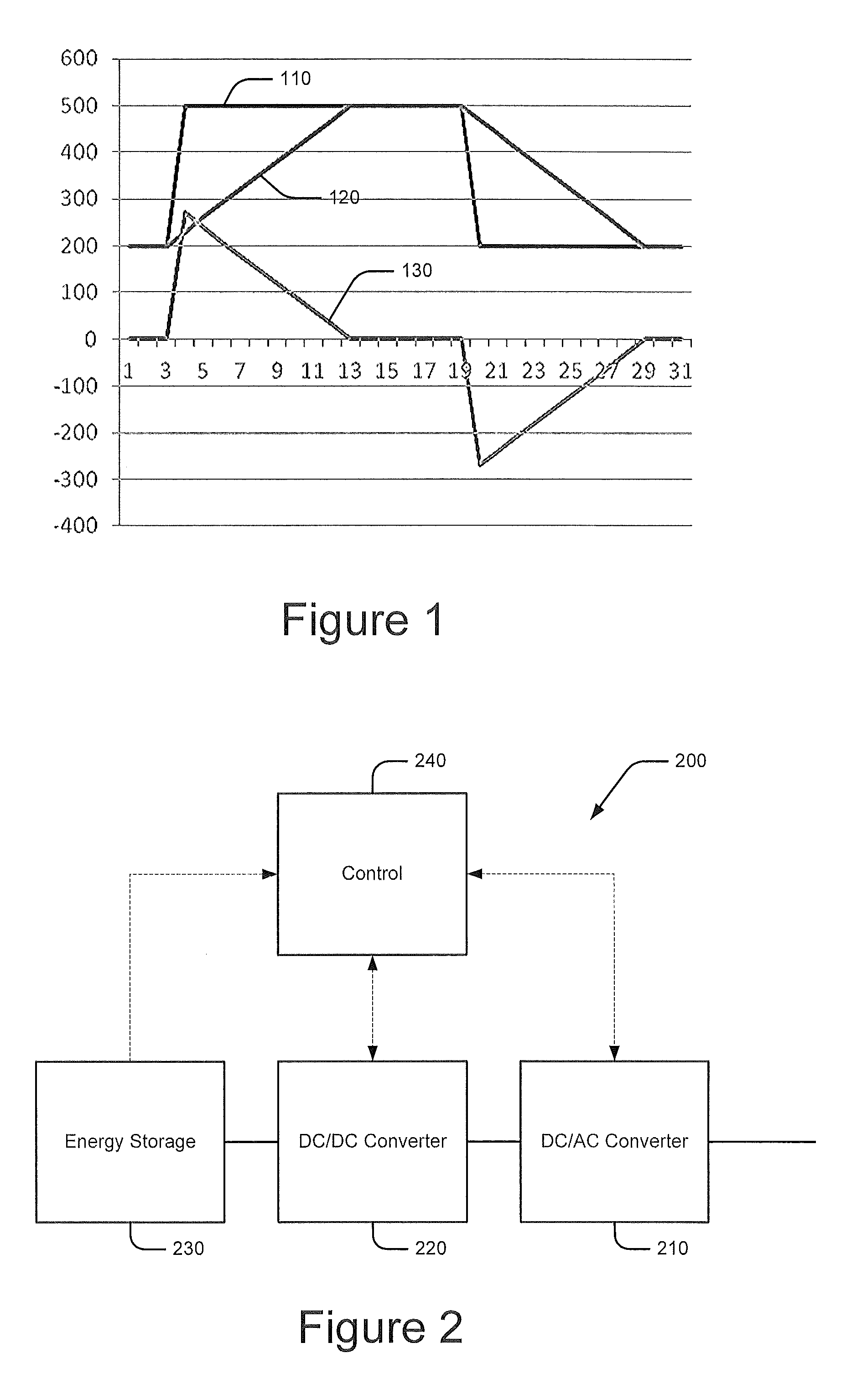
FIG. 1 illustrates operations of a solid state generator (SSG) system with respect to step load changes according to some embodiments.
FIG. 2 is a schematic diagram of an SSG system according to some embodiments.
FIG. 3 is a schematic diagram illustrating a power system including plural fixed speed generator systems, a variable speed generator system and an SSG system according to some embodiments.
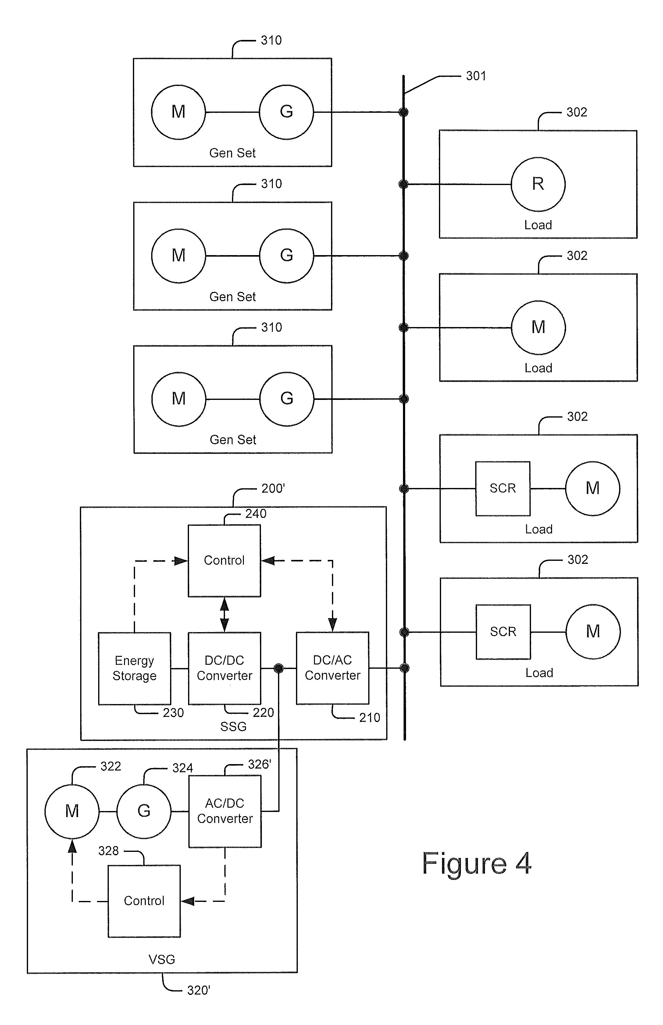
FIG. 4 is a schematic diagram illustrating a power system including plural fixed speed generator systems and a variable speed generator system interfaced to a load bus via an SSG system according to further embodiments.
FIGS. 5A-B are a flowchart illustrating operations of a power system according to some embodiments.
DETAILED DESCRIPTION
Embodiments of the inventive subject matter now will be described more fully hereinafter with reference to the accompanying drawings, in which embodiments of the inventive subject matter are shown. This inventive subject matter may, however, be embodied in many different forms and should not be construed as limited to the embodiments set forth herein. Rather, these embodiments are provided so that this disclosure will be thorough and complete, and will fully convey the scope of the inventive subject matter to those skilled in the art. Like numbers refer to like elements throughout.
It will be understood that, although the terms first, second, etc. may be used herein to describe various elements, these elements should not be limited by these terms. These terms are only used to distinguish one element from another. For example, a first element could be termed a second element, and, similarly, a second element could be termed a first element, without departing from the scope of the inventive subject matter. As used herein, the term "and/or" includes any and all combinations of one or more of the associated listed items.
It will be understood that when an element is referred to as being "connected" or "coupled" to another element, it can be directly connected or coupled to the other element or intervening elements may be present. In contrast, when an element is referred to as being "directly connected" or "directly coupled" to another element, there are no intervening elements present. It will be further understood that elements "coupled in series" or "serially connected" may be directly coupled or may be coupled via intervening elements.
Throughout the specification, like reference numerals in the drawings denote like elements. The terminology used herein is for the purpose of describing particular embodiments only and is not intended to be limiting of the inventive subject matter. As used herein, the singular forms "a", "an" and "the" are intended to include the plural forms as well, unless the context clearly indicates otherwise. It will be further understood that the terms "comprises" "comprising," "includes" and/or "including" when used herein, specify the presence of stated features, integers, steps, operations, elements, and/or components, but do not preclude the presence or addition of one or more other features, integers, steps, operations, elements, components, and/or groups thereof.
Unless otherwise defined, all terms (including technical and scientific terms) used herein have the same meaning as commonly understood by one of ordinary skill in the art to which this inventive subject matter belongs. It will be further understood that terms used herein should be interpreted as having a meaning that is consistent with their meaning in the context of this specification and the relevant art and will not be interpreted in an idealized or overly formal sense unless expressly so defined herein. The term "plurality" is used herein to refer to two or more of the referenced item.
According to some embodiments, a Solid State Generator (SSG) offers a solution that supplies a load transient required by a load, allowing the generator respond to a lower rate of load application that will maintain the load voltage and frequency within specifications. This time shifting of the load step may use a form of energy store, such as capacitors and/or electrochemical storage. This can reduce operating costs and improve system dynamic performance.
FIG. 1 is a graph that shows how an SSG can provide the initial transient needs for a load. The figure illustrates the power interaction between the load 110, generator 120 and the SSG 130 for a load step on and off. The SSG controls slowly ramp down the power demand from the generator so that the generator will see a gradual loading and the voltage and frequency may remain within specification.
FIG. 2 shows a block diagram of an SSG system 200 according to some embodiments. A DC/AC converter 210 is connected between a DC bus and a 3-phase AC bus that supports a load. The 3-phase converter may have 5 terminals; positive, negative and 3 AC phase legs. The DC bus is connected to the positive and negative terminals and the DC/AC converter 210 may include 3 legs coupled to respective phases of the AC load bus through an inductor, The DC/AC converter 210 may be capable of using the DC bus and producing 3-phase AC voltages to support the load and it can transfer power from the AC bus to the DC bus. The 3-phase converter can look like a source or load depending on how the legs are controlled. A DC/DC converter 220 couples one or more energy storage devices 230 to the DC bus and can be individual DC to DC converters for each energy storage device. Each converter can transfer power to and from the DC bus as required. Alternately, the converter can be a 3-phase converter described above but the individual legs are coupled to the energy store using inductors as described in United States Provisional Patent Application Ser. No. 61/771,403 entitled "Hybrid Energy Storage System and Methods", filed Mar. 1, 2013 and U.S. patent application Ser. No. 14/190,398 entitled "Hybrid Energy Storage System and Methods"filed Feb. 26, 2014, the disclosures of each of which are incorporated herein by reference in their entirety. A control circuit 240 controls the DC/DC converter 220 and the DC/AC converter 210 and, as shown, may also monitor and/or control the one or more energy storage devices 230.
In some applications, peak load may exceed generator capacity by a small fraction of total generator capacity. In these applications, conventional solutions may add one or more generators of the same size. If the load is remains small with respect to a single generator, there may be a need to add a resistive load to meet minimum generator load requirements. Under these conditions, it is advantageous to provide a smaller generator increment but it is more problematic to parallel with the other generators.
According to some embodiments, a Variable Speed Generator (VSG) system may resolve these problems. A VSG system may use an engine whose speed is varied but produces a fixed DC voltage or a fixed frequency 3-phase waveform (e.g., using a DC to AC converter) over the speed range of the generator engine. In some embodiments, a VSG may used in at least two ways: (1) using a regulated DC voltage produced by a VSG as an input to a SSG and (2) coupling an SSG to the load bus along with a VSG.
FIG. 3 illustrates a configuration in which an SSG system 200 is coupled to an AC load bus 301 having various loads 302 coupled thereto and that is served by one or more fixed speed generator sets 310 and also served by a VSG generator set 320. As shown, the VSG generator set 320 includes a motor 322 (e.g., a diesel or natural gas engine), a generator 324 and a frequency converter 326. The characteristic of the VSG generator set 320 is that the generator 324 does not need to rotate at a specific speed to produce an output with a fixed frequency, as the frequency converter 320 may maintain the desired frequency.
Fuel savings may be achieved by operating the generator 324 at lower speeds at lighter loads and higher speeds for greater loads.
FIG. 4 illustrates another configuration in which a VSG set is integrated in a combined VSG+SSG system. This implementation uses a VSG system 320' that has an AC/DC converter 326' coupled to a generator 324 and that produces a regulated DC output. This DC output is coupled to the DC bus of an SSG system 200' having a DC/AC converter 210 that is coupled to a load bus 301. This transfers power produced by the generator 324 to the bus 301 to support the load. In this implementation, the SSG system 200' uses a DC/DC converter 220 to couple energy storage 230 to the shared DC bus. This configuration can time shift a load step so the rate of loading or unloading of the generators is maintained at a level to keep the voltage and frequency of the load bus in specification.
This approach combines the variable speed generator and the SSG function by connecting the variable speed generator DC output to the DC bus. This allows for a reduced number of components and may provide better control of system performance. The SSG system 200' may use a DC/DC converter to supply the DC bus from a capacitor and/or electrochemical store. A control system may, for example, monitor the number of generators available, how many are online and the percent loading for each.
When the VSG system 320' is active, the variable speed generator controls can respond based on the voltage of the DC bus. For example, when the DC bus voltage exceeds a first level for some period of time (e.g., 30 seconds), the variable speed generator may be turned off but the control system may continue to monitor the DC bus voltage. When the DC voltage falls below the first level for some period of time (e.g., 30 seconds), the variable speed generator may be started and warmed up. After a brief warm up interval, the variable speed generator rectifier may be operated to maintain the DC bus at a second level which is lower than the first level. The variable speed generator controls may limit the power supplied by the variable speed generator to a maximum value even if the DC voltage cannot be maintained by the variable speed generator. There also may be a protection level that is much lower than the first and second levels where the generator controls disconnect the variable speed generator from the DC bus. At a third voltage level that is below the first and second levels, the electrochemical storage may be used to support the DC bus voltage. This third voltage level is higher than the protection level but lower than the second voltage level. Operation at this voltage level may allow the variable generator and the electrochemical energy stores to concurrently provide power to the load.
This arrangement of voltage levels enables selection of the sources that will be used to support the load. Another feature of the system is that the converters (except the variable speed generator rectifier) may be capable of supplying and receiving power. This type of converter allows current flow into and out of each energy store. The same converters that discharge the energy store can recharge it by reversing the current.
The power supplied by the various sources may be controlled by the droop of the DC bus voltage between the first level and the third level. For example, if the DC bus voltage falls to the second level, the variable speed generator may supply a minimum amount of power to the DC bus. As the DC bus voltage continues to fall, the generator may supply increasing amounts of power until the DC bus voltage has fallen to the third level. At the third voltage level, the variable speed generator may be supplying maximum power to the DC bus. The generator controls may limit the current and/or power supplied to prevent damage to the variable speed generator. At this third level, the variable speed generator is supplying maximum power and the two types of energy stores may also be supplying power to the load and/or recharging independently.
Since the generator and energy stores can be controlled and supply load requirements independently, the SSG and VSG elements can be sized individually to meet the load requirements. The SSG element may be sized based on the total generator capacity and the maximum step load that will be experienced. The VSG element may be sized to support loads that are a fraction of the main generator size. This method of system sizing offers the ability to support very large load steps and turn off the large generators during prolonged light load conditions. This can provide significant cost savings along with reduction in emissions and fuel consumption.
In various embodiments, fixed speed generators, VSG and energy storage can be allocated based on load demand as shown in FIGS. 5A and 5B. Referring to FIG. 5A, a load on the load bus may be compared with available generation capacity (block 505). If the load is less than the amount of capacity currently on line, the amount of on-line capacity may be reduced to a level that supports the current load (blocks 510, 515). If the load increases above the online capacity, a minimum number of generators may be started to support the load (blocks 520, 525).
Referring to FIG. 5B, if the load is greater than the capacity of the VSG system and the energy storage is sufficiently charged, the system continues operation using the currently online generation (blocks 540 and 550). If the load is less than the capacity of the VSG system and the energy storage is sufficiently charged, the VSG may be deactivated and the load powered from the energy storage (blocks 530, 535 and 540). If the energy storage is not sufficiently charged, but is still charged to a level above a recharge threshold, the VSG may continue to serve the load (blocks 535 and 540). If the energy storage charge level is sufficiently low, the VSG is off-line and excess power is available from non-VSG online generation, the energy storage devices may be charged (blocks 545, 555 and 560). If excess power is not available, the VSG may be started and used to charge the energy storage (blocks 565, 560).
In a first scenario, the load is light and can be supported by the variable speed generator. The control system may send a signal to the other generators on the load bus to turn off. The variable speed generator may supply the load bus and the load transients are supplied by the energy storage devices (e.g., capacitors) using the SSG function. If the load is lighter than the variable speed generator, the variable speed generator can be operated in an on/off mode where the electrochemical storage supplies the power during the off intervals and the generator supplies the load and recharges the battery during the on intervals. This operating mode allows the variable speed generator to operate at higher efficiency. This operating mode may offer the highest efficiency because the fixed speed generators are off and the variable speed generator is operated at maximum efficiency.
In a second scenario, the load is increased beyond the capabilities of the variable speed generator. The control system may send a command to start sufficient additional generators to support the applied load. The SSG function may use the capacitor and/or the electrochemical stores to supply the load until the generators are started and assume the load. After the generators are supplying the load bus, the SSG energy stores may be recharged by the excess capacity of the generators. The variable speed generator may be turned off if sufficient generator capacity is available. The SSG may control load transients by time shifting the transient to maintain a rate of change in generator loading to keep the voltage and frequency change within specifications. Again, in this operating mode, the generator availability may be configured to meet to the load requirements and offer desirable system efficiency and emissions.
In a third scenario, the load increases beyond the capabilities of the variable speed generator alone. As in the second scenario, the control system may send a command to start sufficient additional generators to support the load. The variable speed generator may be sized to be a fraction of the capacity of the other generators and the control system can use the variable speed generator to supply the load with the other generators to support the load without starting one of the other generators. The SSG may control load transients by time shifting the transients to maintain a rate of change in generator loading to keep the voltage and frequency change within specifications. This may improve system efficiency by maximizing main generator loading and making best use of the available sources.
In fourth scenario, the load is increased beyond the capabilities of the variable speed generator alone. As in the second and third scenarios, the control system may send a command to start sufficient additional generators to support the load. If the load is higher than all the available sources, the VSG system can use all the energy stores to support this overload. Since the overload cannot be supported indefinitely, the control system may activate an alarm to notify the operator of an unsustainable condition.
In all of the above described scenarios, the control system may monitor the load and individual generator loading. The control system may power down excess generation capacity to provide a minimum generator loading and desired efficiency under varying load conditions. A system combining the SSG+VSG function enables a single converter to provide the time shifting of load demands under any combination of VSG and main generator operating modes.
In the drawings and specification, there have been disclosed typical embodiments of the inventive subject matter and, although specific terms are employed, they are used in a generic and descriptive sense only and not for purposes of limitation, the scope of the inventive subject matter being set forth in the following claims.
* * * * *
D00000
D00001
D00002
D00003
D00004
D00005
XML
uspto.report is an independent third-party trademark research tool that is not affiliated, endorsed, or sponsored by the United States Patent and Trademark Office (USPTO) or any other governmental organization. The information provided by uspto.report is based on publicly available data at the time of writing and is intended for informational purposes only.
While we strive to provide accurate and up-to-date information, we do not guarantee the accuracy, completeness, reliability, or suitability of the information displayed on this site. The use of this site is at your own risk. Any reliance you place on such information is therefore strictly at your own risk.
All official trademark data, including owner information, should be verified by visiting the official USPTO website at www.uspto.gov. This site is not intended to replace professional legal advice and should not be used as a substitute for consulting with a legal professional who is knowledgeable about trademark law.