Method of producing a veneered element and such a veneered element
Lundblad , et al.
U.S. patent number 10,286,633 [Application Number 15/308,737] was granted by the patent office on 2019-05-14 for method of producing a veneered element and such a veneered element. This patent grant is currently assigned to VALINGE INNOVATION AB. The grantee listed for this patent is VALINGE INNOVATION AB. Invention is credited to Christer Lundblad, Thomas Meijer, Per Nygren, Goran Ziegler.


| United States Patent | 10,286,633 |
| Lundblad , et al. | May 14, 2019 |
Method of producing a veneered element and such a veneered element
Abstract
A method of producing a veneered element, the method including providing a substrate, applying a sub-layer on a surface of the substrate, applying a veneer layer on the sub-layer, and applying pressure to the veneer layer and/or the substrate, such that at least a portion of the sub-layer permeates through the veneer layer. Also, such a veneered element.
| Inventors: | Lundblad; Christer (Orkelljunga, SE), Nygren; Per (Ramlosa, SE), Meijer; Thomas (Viken, SE), Ziegler; Goran (Viken, SE) | ||||||||||
|---|---|---|---|---|---|---|---|---|---|---|---|
| Applicant: |
|
||||||||||
| Assignee: | VALINGE INNOVATION AB (Viken,
SE) |
||||||||||
| Family ID: | 54480310 | ||||||||||
| Appl. No.: | 15/308,737 | ||||||||||
| Filed: | May 11, 2015 | ||||||||||
| PCT Filed: | May 11, 2015 | ||||||||||
| PCT No.: | PCT/SE2015/050524 | ||||||||||
| 371(c)(1),(2),(4) Date: | November 03, 2016 | ||||||||||
| PCT Pub. No.: | WO2015/174909 | ||||||||||
| PCT Pub. Date: | November 19, 2015 |
Prior Publication Data
| Document Identifier | Publication Date | |
|---|---|---|
| US 20170190156 A1 | Jul 6, 2017 | |
Related U.S. Patent Documents
| Application Number | Filing Date | Patent Number | Issue Date | ||
|---|---|---|---|---|---|
| PCT/SE2015/050008 | Jan 9, 2015 | ||||
| 14593458 | Jan 9, 2015 | ||||
Foreign Application Priority Data
| May 12, 2014 [SE] | 1450552 | |||
| Sep 29, 2014 [SE] | 1451154 | |||
| Current U.S. Class: | 1/1 |
| Current CPC Class: | B32B 21/14 (20130101); B27D 1/06 (20130101); B32B 27/36 (20130101); B32B 27/40 (20130101); B32B 27/302 (20130101); B32B 21/00 (20130101); B32B 27/20 (20130101); B32B 27/304 (20130101); B27D 1/00 (20130101); B32B 27/32 (20130101); B27M 3/04 (20130101); B32B 3/30 (20130101); B44C 5/04 (20130101); B32B 27/30 (20130101); B32B 27/365 (20130101); B32B 21/08 (20130101); B44C 5/043 (20130101); B32B 2419/04 (20130101); B32B 2307/4026 (20130101); B32B 2307/102 (20130101); B32B 2264/067 (20130101); B32B 2607/00 (20130101) |
| Current International Class: | B32B 21/14 (20060101); B32B 27/40 (20060101); B32B 3/30 (20060101); B27D 1/06 (20060101); B32B 21/00 (20060101); B27D 1/00 (20060101); B32B 27/36 (20060101); B32B 21/08 (20060101); B32B 27/30 (20060101); B32B 27/32 (20060101); B32B 27/20 (20060101); B44C 5/04 (20060101); B27M 3/04 (20060101) |
| Field of Search: | ;428/537.1 |
References Cited [Referenced By]
U.S. Patent Documents
| 2018712 | October 1935 | Elmendorf |
| 2419614 | April 1947 | Welch |
| 2587064 | February 1952 | Rapson |
| 2630395 | March 1953 | McCullough |
| 2634534 | April 1953 | Brown |
| 2695857 | November 1954 | Rehbock et al. |
| 2720478 | October 1955 | Hogg |
| 2831794 | April 1958 | Elmendorf |
| 2932596 | April 1960 | Abbs |
| 2962081 | November 1960 | Dobry et al. |
| 2992152 | July 1961 | Chapman |
| 3032820 | May 1962 | Johnson |
| 3135643 | June 1964 | Michl |
| 3286006 | November 1966 | Annand |
| 3308013 | March 1967 | Bryant |
| 3325302 | June 1967 | Hosfeld |
| 3342621 | September 1967 | Point et al. |
| 3345234 | October 1967 | Jecker et al. |
| 3392082 | July 1968 | Lloyd |
| 3426730 | February 1969 | Lawson et al. |
| 3463653 | August 1969 | Letter |
| 3486484 | December 1969 | Bullough |
| 3533725 | October 1970 | Bridgeford |
| 3540976 | November 1970 | Ames |
| 3565665 | February 1971 | Stranch et al. |
| 3578522 | May 1971 | Rauch |
| 3615279 | October 1971 | Ward, Jr. |
| 3673020 | June 1972 | De Jaeger |
| 3729368 | April 1973 | Ingham et al. |
| 3844863 | October 1974 | Forsythe |
| 3846219 | November 1974 | Kunz |
| 3880687 | April 1975 | Elmendorf et al. |
| 3895984 | July 1975 | Cone et al. |
| 3897185 | July 1975 | Beyer |
| 3897588 | July 1975 | Nohtomi |
| 3914359 | October 1975 | Bevan |
| 3950599 | April 1976 | Board, Jr. |
| 3956542 | May 1976 | Roberti |
| 3961108 | June 1976 | Rosner et al. |
| 4052739 | October 1977 | Wada et al. |
| 4093766 | June 1978 | Scher et al. |
| 4115178 | September 1978 | Cone et al. |
| 4126725 | November 1978 | Shiflet |
| 4131705 | December 1978 | Kubinsky |
| 4277527 | July 1981 | Duhl |
| 4311621 | January 1982 | Nishizawa et al. |
| 4313857 | February 1982 | Blount |
| 4337290 | June 1982 | Kelly et al. |
| 4361612 | November 1982 | Shaner |
| 4420351 | December 1983 | Lussi |
| 4420525 | December 1983 | Parks |
| 4430375 | February 1984 | Scher et al. |
| 4430380 | February 1984 | Honel |
| 4474920 | October 1984 | Kyminas et al. |
| 4743484 | May 1988 | Robbins |
| 4863777 | September 1989 | Callaway et al. |
| 4872825 | October 1989 | Ross |
| 4890656 | January 1990 | Ohsumi et al. |
| 4911969 | March 1990 | Ogata et al. |
| 4942084 | July 1990 | Prince |
| 5034272 | July 1991 | Lindgren et al. |
| 5059472 | October 1991 | Le Bell |
| 5085930 | February 1992 | Widmann et al. |
| 5147486 | September 1992 | Hoffman |
| 5206066 | April 1993 | Horacek |
| 5246765 | September 1993 | Lussi et al. |
| 5258216 | November 1993 | Von Bonin et al. |
| 5292576 | March 1994 | Sanders |
| 5314554 | May 1994 | Owens |
| 5354259 | October 1994 | Scholz et al. |
| 5405705 | April 1995 | Fujimoto |
| 5422170 | June 1995 | Iwata et al. |
| 5447752 | September 1995 | Cobb |
| 5466511 | November 1995 | O'Dell et al. |
| 5543193 | August 1996 | Tesch |
| 5569424 | October 1996 | Amour |
| 5601930 | February 1997 | Mehta et al. |
| 5604025 | February 1997 | Tesch |
| 5609966 | March 1997 | Perrin et al. |
| 5755068 | May 1998 | Ormiston |
| 5766522 | June 1998 | Daly et al. |
| 5827788 | October 1998 | Miyakoshi |
| 5855832 | January 1999 | Clausi |
| 5891564 | April 1999 | Shultz et al. |
| 5925211 | July 1999 | Rakauskas |
| 5925296 | July 1999 | Leese |
| 5942072 | August 1999 | McKinnon |
| 5976689 | November 1999 | Witt et al. |
| 6036137 | March 2000 | Myren |
| 6103377 | August 2000 | Clausi |
| 6238750 | May 2001 | Correll et al. |
| 6291625 | September 2001 | Hosgood |
| 6468645 | October 2002 | Clausi |
| 6481476 | November 2002 | Okamoto |
| 6521326 | February 2003 | Fischer et al. |
| 6528437 | March 2003 | Hepfinger et al. |
| 6537610 | March 2003 | Springer et al. |
| 6620349 | September 2003 | Lopez |
| 6667108 | December 2003 | Ellstrom |
| 6769217 | August 2004 | Nelson |
| 6773799 | August 2004 | Persson et al. |
| 6803110 | October 2004 | Drees et al. |
| 6926954 | August 2005 | Shuren et al. |
| 6991830 | January 2006 | Hansson et al. |
| 7022756 | April 2006 | Singer |
| 7485693 | February 2009 | Matsuda et al. |
| 7811489 | October 2010 | Pervan |
| 8021741 | September 2011 | Chen |
| 8245477 | August 2012 | Pervan |
| 8302367 | November 2012 | Schulte |
| 8349234 | January 2013 | Ziegler et al. |
| 8349235 | January 2013 | Pervan et al. |
| 8407963 | April 2013 | Schulte |
| 8419877 | April 2013 | Pervan et al. |
| 8431054 | April 2013 | Pervan et al. |
| 8480841 | July 2013 | Pervan et al. |
| 8481111 | July 2013 | Ziegler et al. |
| 8499520 | August 2013 | Schulte |
| 8617439 | December 2013 | Pervan et al. |
| 8635829 | January 2014 | Schulte |
| 8650738 | February 2014 | Schulte |
| 8663785 | March 2014 | Ziegler et al. |
| 8728564 | May 2014 | Ziegler et al. |
| 8752352 | June 2014 | Schulte |
| 8784587 | July 2014 | Lindgren et al. |
| 8920874 | December 2014 | Ziegler et al. |
| 8920876 | December 2014 | Vetter et al. |
| 8993049 | March 2015 | Pervan |
| 9085905 | July 2015 | Persson et al. |
| 9109366 | August 2015 | Schulte |
| 9181698 | November 2015 | Pervan et al. |
| 9255405 | February 2016 | Pervan et al. |
| 9296191 | March 2016 | Pervan et al. |
| 9352499 | May 2016 | Ziegler et al. |
| 9403286 | August 2016 | Vetter et al. |
| 9410319 | August 2016 | Ziegler et al. |
| 9556622 | January 2017 | Pervan et al. |
| 9783996 | October 2017 | Pervan et al. |
| 10017950 | July 2018 | Pervan |
| 10100535 | October 2018 | Pervan et al. |
| 10214913 | February 2019 | Persson et al. |
| 2001/0006704 | July 2001 | Chen et al. |
| 2001/0009309 | July 2001 | Taguchi et al. |
| 2002/0031620 | March 2002 | Yuzawa et al. |
| 2002/0054994 | May 2002 | Dupre et al. |
| 2002/0100231 | August 2002 | Miller |
| 2003/0008130 | January 2003 | Kaneko |
| 2003/0056873 | March 2003 | Nakos et al. |
| 2003/0059639 | March 2003 | Worsley |
| 2003/0102094 | June 2003 | Tirri et al. |
| 2003/0108760 | June 2003 | Haas et al. |
| 2003/0208980 | November 2003 | Miller et al. |
| 2004/0088946 | May 2004 | Liang et al. |
| 2004/0123542 | July 2004 | Grafenauer |
| 2004/0191547 | September 2004 | Oldorff |
| 2004/0202857 | October 2004 | Singer |
| 2004/0206036 | October 2004 | Pervan |
| 2004/0237436 | December 2004 | Zuber et al. |
| 2004/0250911 | December 2004 | Vogel |
| 2005/0003099 | January 2005 | Quist |
| 2005/0016107 | January 2005 | Rosenthal et al. |
| 2005/0079780 | April 2005 | Rowe et al. |
| 2005/0136234 | June 2005 | Hak et al. |
| 2005/0153150 | July 2005 | Wellwood et al. |
| 2005/0193677 | September 2005 | Vogel |
| 2005/0208255 | September 2005 | Pervan |
| 2005/0227040 | October 2005 | Toupalik |
| 2005/0252130 | November 2005 | Martensson |
| 2006/0008630 | January 2006 | Thiers et al. |
| 2006/0024465 | February 2006 | Briere |
| 2006/0032175 | February 2006 | Chen et al. |
| 2006/0048474 | March 2006 | Pervan et al. |
| 2006/0070321 | April 2006 | Au |
| 2006/0070325 | April 2006 | Magnusson |
| 2006/0145384 | July 2006 | Singer |
| 2006/0154015 | July 2006 | Miller et al. |
| 2006/0172118 | August 2006 | Han et al. |
| 2006/0182938 | August 2006 | Oldorff |
| 2006/0183853 | August 2006 | Sczepan |
| 2007/0055012 | March 2007 | Caldwell |
| 2007/0066176 | March 2007 | Wenstrup et al. |
| 2007/0102108 | May 2007 | Zheng |
| 2007/0148339 | June 2007 | Wescott |
| 2007/0166516 | July 2007 | Kim et al. |
| 2007/0184244 | August 2007 | Doehring |
| 2007/0207296 | September 2007 | Eisermann |
| 2007/0218260 | September 2007 | Miclo et al. |
| 2007/0224438 | September 2007 | Van Benthem et al. |
| 2007/0256804 | November 2007 | Garcis Espino et al. |
| 2008/0000179 | January 2008 | Pervan et al. |
| 2008/0000417 | January 2008 | Pervan et al. |
| 2008/0032120 | February 2008 | Braun |
| 2008/0090032 | April 2008 | Perrin et al. |
| 2008/0093013 | April 2008 | Muller |
| 2008/0152876 | June 2008 | Magnusson |
| 2008/0176039 | July 2008 | Chen et al. |
| 2008/0263985 | October 2008 | Hasch et al. |
| 2009/0056257 | March 2009 | Mollinger et al. |
| 2009/0124704 | May 2009 | Jenkins |
| 2009/0135356 | May 2009 | Ando |
| 2009/0145066 | June 2009 | Pervan |
| 2009/0155612 | June 2009 | Pervan et al. |
| 2009/0165946 | July 2009 | Suzuki |
| 2009/0208646 | August 2009 | Kreuder et al. |
| 2009/0294037 | December 2009 | Oldorff |
| 2009/0311433 | December 2009 | Wittmann |
| 2010/0092731 | April 2010 | Pervan et al. |
| 2010/0136303 | June 2010 | Kreuder |
| 2010/0196678 | August 2010 | Vermeulen |
| 2010/0223881 | September 2010 | Kalwa |
| 2010/0239820 | September 2010 | Buhlmann |
| 2010/0291397 | November 2010 | Pervan et al. |
| 2010/0300030 | December 2010 | Pervan et al. |
| 2010/0304089 | December 2010 | Magnusson |
| 2010/0307675 | December 2010 | Buhlmann |
| 2010/0307677 | December 2010 | Buhlmann |
| 2010/0314368 | December 2010 | Groeke |
| 2010/0319282 | December 2010 | Ruland |
| 2010/0323187 | December 2010 | Kalwa |
| 2010/0330376 | December 2010 | Trksak |
| 2011/0175251 | July 2011 | Ziegler et al. |
| 2011/0177319 | July 2011 | Ziegler et al. |
| 2011/0177354 | July 2011 | Ziegler et al. |
| 2011/0189448 | August 2011 | Lindgren et al. |
| 2011/0247748 | October 2011 | Pervan et al. |
| 2011/0250404 | October 2011 | Pervan et al. |
| 2011/0262720 | October 2011 | Riebel et al. |
| 2011/0274872 | November 2011 | Yu |
| 2011/0283642 | November 2011 | Meirlaen et al. |
| 2011/0283650 | November 2011 | Pervan et al. |
| 2011/0287211 | November 2011 | Bailey et al. |
| 2011/0293823 | December 2011 | Bruderer et al. |
| 2011/0293906 | December 2011 | Jacobsson |
| 2012/0048487 | March 2012 | Brewster |
| 2012/0124932 | May 2012 | Schulte et al. |
| 2012/0263878 | October 2012 | Ziegler et al. |
| 2012/0263965 | October 2012 | Persson et al. |
| 2012/0264853 | October 2012 | Ziegler et al. |
| 2012/0276348 | November 2012 | Clausi et al. |
| 2012/0288689 | November 2012 | Hansson et al. |
| 2012/0308774 | December 2012 | Persson et al. |
| 2013/0025216 | January 2013 | Reichwein et al. |
| 2013/0092314 | April 2013 | Zeigler et al. |
| 2013/0095315 | April 2013 | Pervan et al. |
| 2013/0111845 | May 2013 | Pervan et al. |
| 2013/0189534 | July 2013 | Pervan et al. |
| 2013/0196119 | August 2013 | Dobecz |
| 2013/0269863 | October 2013 | Pervan et al. |
| 2013/0273244 | October 2013 | Vetter et al. |
| 2013/0273245 | October 2013 | Ziegler et al. |
| 2014/0027020 | January 2014 | Klaeusler et al. |
| 2014/0044872 | February 2014 | Pervan |
| 2014/0075874 | March 2014 | Pervan et al. |
| 2014/0147585 | May 2014 | Smith |
| 2014/0171554 | June 2014 | Ziegler et al. |
| 2014/0178630 | June 2014 | Pervan et al. |
| 2014/0186610 | July 2014 | Pervan |
| 2014/0199558 | July 2014 | Pervan et al. |
| 2014/0234531 | August 2014 | Ziegler et al. |
| 2014/0290171 | October 2014 | Vermeulen |
| 2015/0017461 | January 2015 | Lindgren et al. |
| 2015/0072111 | March 2015 | Rischer et al. |
| 2015/0079280 | March 2015 | Vetter et al. |
| 2015/0093502 | April 2015 | Ziegler et al. |
| 2015/0111055 | April 2015 | Persson et al. |
| 2015/0159382 | June 2015 | Pervan |
| 2015/0197942 | July 2015 | Pervan et al. |
| 2015/0197943 | July 2015 | Ziegler et al. |
| 2015/0275526 | October 2015 | Persson et al. |
| 2015/0298433 | October 2015 | Kalwa |
| 2016/0031189 | February 2016 | Pervan et al. |
| 2016/0114495 | April 2016 | Pervan et al. |
| 2016/0186318 | June 2016 | Pervan et al. |
| 2016/0230400 | August 2016 | Pervan et al. |
| 2016/0368180 | December 2016 | Ziegler et al. |
| 2016/0369507 | December 2016 | Pervan et al. |
| 2016/0375674 | December 2016 | Schulte |
| 2017/0120564 | May 2017 | Schulte |
| 2017/0165936 | June 2017 | Schulte |
| 2017/0305119 | October 2017 | Bergelin et al. |
| 2017/0348984 | December 2017 | Pervan et al. |
| 2018/0002934 | January 2018 | Pervan et al. |
| 2018/0291638 | October 2018 | Pervan |
| 2018/0370278 | December 2018 | Persson et al. |
| 2019/0010711 | January 2019 | Pervan et al. |
| 80284/75 | Jun 1975 | AU | |||
| 2011236087 | Oct 2011 | AU | |||
| 2 557 096 | Jul 2005 | CA | |||
| 2 652 656 | Apr 2013 | CA | |||
| 298894 | May 1954 | CH | |||
| 1709717 | Dec 2005 | CN | |||
| 102166775 | Aug 2011 | CN | |||
| 202200608 | Apr 2012 | CN | |||
| 104084994 | Oct 2014 | CN | |||
| 1 815 312 | Jul 1969 | DE | |||
| 7148789 | Apr 1972 | DE | |||
| 29 39 828 | Apr 1981 | DE | |||
| 33 34 921 | Apr 1985 | DE | |||
| 36 34 885 | Apr 1988 | DE | |||
| 42 33 050 | Apr 1993 | DE | |||
| 42 36 266 | May 1993 | DE | |||
| 202 14 532 | Feb 2004 | DE | |||
| 102 45 914 | Apr 2004 | DE | |||
| 103 00 247 | Jul 2004 | DE | |||
| 103 31 657 | Feb 2005 | DE | |||
| 20 2004 003 061 | Jul 2005 | DE | |||
| 10 2004 050 278 | Apr 2006 | DE | |||
| 20 2006 007 797 | Aug 2006 | DE | |||
| 10 2005 046 264 | Apr 2007 | DE | |||
| 10 2006 024 593 | Dec 2007 | DE | |||
| 10 2006 058 244 | Jun 2008 | DE | |||
| 10 2007 043 202 | Mar 2009 | DE | |||
| 20 2009 008 367 | Sep 2009 | DE | |||
| 10 2010 045 266 | Mar 2012 | DE | |||
| 20 2013 011 776 | Jul 2014 | DE | |||
| 20 2014 102 031 | Jul 2014 | DE | |||
| 20 2013 012 020 | Feb 2015 | DE | |||
| 10 2013 113 125 | May 2015 | DE | |||
| 0 129 430 | Dec 1984 | EP | |||
| 0 234 220 | Sep 1987 | EP | |||
| 0 129 430 | Jan 1990 | EP | |||
| 0 355 829 | Feb 1990 | EP | |||
| 0 611 408 | Dec 1993 | EP | |||
| 0 592 013 | Apr 1994 | EP | |||
| 0 656 443 | Jun 1995 | EP | |||
| 0 611 408 | Sep 1996 | EP | |||
| 0 732 449 | Sep 1996 | EP | |||
| 0 744 477 | Nov 1996 | EP | |||
| 0 914 914 | May 1999 | EP | |||
| 0 732 449 | Aug 1999 | EP | |||
| 0 744 477 | Jan 2000 | EP | |||
| 0 993 934 | Apr 2000 | EP | |||
| 1 035 255 | Sep 2000 | EP | |||
| 1 125 971 | Aug 2001 | EP | |||
| 1 136 251 | Sep 2001 | EP | |||
| 1 193 283 | Apr 2002 | EP | |||
| 1 209 199 | May 2002 | EP | |||
| 1 242 702 | Sep 2002 | EP | |||
| 1 249 322 | Oct 2002 | EP | |||
| 1 262 607 | Dec 2002 | EP | |||
| 1 454 763 | Sep 2004 | EP | |||
| 1 242 702 | Nov 2004 | EP | |||
| 1 498 241 | Jan 2005 | EP | |||
| 1 507 664 | Feb 2005 | EP | |||
| 1 507 664 | Feb 2005 | EP | |||
| 1 584 378 | Oct 2005 | EP | |||
| 1 657 055 | May 2006 | EP | |||
| 1 681 103 | Jul 2006 | EP | |||
| 1 690 603 | Aug 2006 | EP | |||
| 1 808 311 | Jul 2007 | EP | |||
| 1 847 385 | Oct 2007 | EP | |||
| 1 961 556 | Aug 2008 | EP | |||
| 1 985 464 | Oct 2008 | EP | |||
| 1 997 623 | Dec 2008 | EP | |||
| 2 025 484 | Feb 2009 | EP | |||
| 1 454 763 | Aug 2009 | EP | |||
| 2 105 320 | Sep 2009 | EP | |||
| 2 119 550 | Nov 2009 | EP | |||
| 2 213 476 | Aug 2010 | EP | |||
| 2 226 201 | Sep 2010 | EP | |||
| 2 246 500 | Nov 2010 | EP | |||
| 2 263 867 | Dec 2010 | EP | |||
| 2 264 259 | Dec 2010 | EP | |||
| 2 272 667 | Jan 2011 | EP | |||
| 2 272 668 | Jan 2011 | EP | |||
| 2 305 462 | Apr 2011 | EP | |||
| 1 847 385 | Sep 2011 | EP | |||
| 2 415 947 | Feb 2012 | EP | |||
| 2 263 867 | Mar 2012 | EP | |||
| 2 902 196 | Jan 2014 | EP | |||
| 2 902 196 | Aug 2016 | EP | |||
| 801 433 | Aug 1936 | FR | |||
| 2 873 953 | Feb 2006 | FR | |||
| 984 170 | Feb 1965 | GB | |||
| 1090450 | Nov 1967 | GB | |||
| 1 561 820 | Mar 1980 | GB | |||
| 2 238 983 | Jun 1991 | GB | |||
| 2 248 246 | Apr 1992 | GB | |||
| 2 464 541 | Apr 2010 | GB | |||
| S51-128409 | Nov 1976 | JP | |||
| S52-087212 | Jul 1977 | JP | |||
| S56-049259 | May 1981 | JP | |||
| S56-151564 | Nov 1981 | JP | |||
| S58-084761 | May 1983 | JP | |||
| S59-101312 | Jun 1984 | JP | |||
| S64-062108 | Mar 1989 | JP | |||
| H02-198801 | Aug 1990 | JP | |||
| 2-229002 | Sep 1990 | JP | |||
| H03-030905 | Feb 1991 | JP | |||
| H03-211047 | Sep 1991 | JP | |||
| H03-267174 | Nov 1991 | JP | |||
| H04-107101 | Apr 1992 | JP | |||
| H04-247901 | Sep 1992 | JP | |||
| H04-269506 | Sep 1992 | JP | |||
| H05-077362 | Mar 1993 | JP | |||
| H05-237809 | Sep 1993 | JP | |||
| H06-312406 | Nov 1994 | JP | |||
| H08-207012 | Aug 1996 | JP | |||
| H09-164651 | Jun 1997 | JP | |||
| H10-002098 | Jan 1998 | JP | |||
| H10-18562 | Jan 1998 | JP | |||
| 11-291203 | Oct 1999 | JP | |||
| 2000-226931 | Aug 2000 | JP | |||
| 2000-263520 | Sep 2000 | JP | |||
| 2003-311718 | Nov 2000 | JP | |||
| 2001-287208 | Oct 2001 | JP | |||
| 2001-329681 | Nov 2001 | JP | |||
| 2003-311717 | Nov 2003 | JP | |||
| 2004-068512 | Mar 2004 | JP | |||
| 2004-076476 | Mar 2004 | JP | |||
| 2005-034815 | Feb 2005 | JP | |||
| 2005-074682 | Mar 2005 | JP | |||
| 2005-170016 | Jun 2005 | JP | |||
| 2005-219215 | Aug 2005 | JP | |||
| 3705482 | Oct 2005 | JP | |||
| 2005-307582 | Nov 2005 | JP | |||
| 2007-098755 | Apr 2007 | JP | |||
| 2007-216692 | Aug 2007 | JP | |||
| 2007-268843 | Oct 2007 | JP | |||
| 2008-188826 | Aug 2008 | JP | |||
| 2010-017963 | Jan 2010 | JP | |||
| 2011-110768 | Jun 2011 | JP | |||
| 225556 | Feb 1992 | NZ | |||
| 469 326 | Jun 1993 | SE | |||
| WO 92/06832 | Apr 1992 | WO | |||
| WO 93/24295 | Dec 1993 | WO | |||
| WO 93/24296 | Dec 1993 | WO | |||
| WO 94/00280 | Jan 1994 | WO | |||
| WO 95/06568 | Mar 1995 | WO | |||
| WO 00/22225 | Apr 2000 | WO | |||
| WO 00/44576 | Aug 2000 | WO | |||
| WO 01/00409 | Jan 2001 | WO | |||
| WO 01/48333 | Jul 2001 | WO | |||
| WO 01/64408 | Sep 2001 | WO | |||
| WO 01/68367 | Sep 2001 | WO | |||
| WO 01/92037 | Dec 2001 | WO | |||
| WO 02/42167 | May 2002 | WO | |||
| WO 02/42373 | May 2002 | WO | |||
| WO 03/078761 | Sep 2003 | WO | |||
| WO 03/095202 | Nov 2003 | WO | |||
| WO 2004/042168 | May 2004 | WO | |||
| WO 2004/050359 | Jun 2004 | WO | |||
| WO 2004/067874 | Aug 2004 | WO | |||
| WO 2005/035209 | Apr 2005 | WO | |||
| WO 2005/035209 | Apr 2005 | WO | |||
| WO 2005/035209 | Apr 2005 | WO | |||
| WO 2005/054599 | Jun 2005 | WO | |||
| WO 2005/054600 | Jun 2005 | WO | |||
| WO 2005/066431 | Jul 2005 | WO | |||
| WO 2005/080096 | Sep 2005 | WO | |||
| WO 2005/097874 | Oct 2005 | WO | |||
| WO 2005/116337 | Dec 2005 | WO | |||
| WO 2005/116361 | Dec 2005 | WO | |||
| WO 2006/007413 | Jan 2006 | WO | |||
| WO 2006/013469 | Feb 2006 | WO | |||
| WO 2006/015313 | Feb 2006 | WO | |||
| WO 2006/042651 | Apr 2006 | WO | |||
| WO 2006/043893 | Apr 2006 | WO | |||
| WO 2006/066776 | Jun 2006 | WO | |||
| WO 2006/126930 | Nov 2006 | WO | |||
| WO 2007/015669 | Feb 2007 | WO | |||
| WO 2007/015669 | Feb 2007 | WO | |||
| WO 2007/042258 | Apr 2007 | WO | |||
| WO 2007/059294 | May 2007 | WO | |||
| WO 2008/004960 | Jan 2008 | WO | |||
| WO 2008/004960 | Jan 2008 | WO | |||
| WO 2008/004960 | Jan 2008 | WO | |||
| WO 2008/148771 | Dec 2008 | WO | |||
| WO 2009/015682 | Feb 2009 | WO | |||
| WO 2009/050565 | Apr 2009 | WO | |||
| WO 2009/065768 | May 2009 | WO | |||
| WO 2009/065769 | May 2009 | WO | |||
| WO 2009/065769 | May 2009 | WO | |||
| WO2009065769 | May 2009 | WO | |||
| WO 2009/080772 | Jul 2009 | WO | |||
| WO 2009/080813 | Jul 2009 | WO | |||
| WO 2009/116926 | Sep 2009 | WO | |||
| WO 2009/124704 | Oct 2009 | WO | |||
| WO 2010/046698 | Apr 2010 | WO | |||
| WO 2010/084466 | Jul 2010 | WO | |||
| WO 2010/087752 | Aug 2010 | WO | |||
| WO 2010/094500 | Aug 2010 | WO | |||
| WO 2011/087422 | Jul 2011 | WO | |||
| WO 2011/087423 | Jul 2011 | WO | |||
| WO 2011/087424 | Jul 2011 | WO | |||
| WO 2011/129755 | Oct 2011 | WO | |||
| WO 2011/129757 | Oct 2011 | WO | |||
| WO 2011/141851 | Nov 2011 | WO | |||
| WO 2012/004699 | Jan 2012 | WO | |||
| WO 2012/076608 | Jun 2012 | WO | |||
| WO 2012/141647 | Oct 2012 | WO | |||
| WO 2012/154113 | Nov 2012 | WO | |||
| WO 2013/056745 | Apr 2013 | WO | |||
| WO 2013/079950 | Jun 2013 | WO | |||
| WO 2013/139460 | Sep 2013 | WO | |||
| WO 2013/182191 | Dec 2013 | WO | |||
| WO 2013/182191 | Dec 2013 | WO | |||
| WO 2014/017972 | Jan 2014 | WO | |||
| WO 2014/109699 | Jul 2014 | WO | |||
| WO 2015/078434 | Jun 2015 | WO | |||
| WO 2015/078443 | Jun 2015 | WO | |||
| WO 2015/078444 | Jun 2015 | WO | |||
| WO 2015/105455 | Jul 2015 | WO | |||
| WO 2015/105456 | Jul 2015 | WO | |||
| WO 2015/174909 | Nov 2015 | WO | |||
| WO 2016/151435 | Sep 2016 | WO | |||
Other References
|
US. Appl. No. 15/496,357, Bergelin et al. cited by applicant . Extended European Search Report issued in EP 15735146.1, dated Jul. 18, 2017, European Patent Office, Munich, DE, 10 pages. cited by applicant . Bergelin, Marcus, et al., U.S. Appl. No. 15/496,357, entitled "A Veneered Element and Method of Producing Such a Veneered Element," filed in the U.S. Patent and Trademark Office on Apr. 25, 2017. cited by applicant . Parquet International, "Digital Printing is still an expensive process," Mar. 2008, cover page/pp. 78-79, www.parkettmagazin.com. cited by applicant . Floor Daily, "Shaw Laminates: Green by Design," Aug. 13, 2007. 1 pg, Dalton, GA. cited by applicant . BTLSR Toledo, Inc. website. http://www.btlresins.com/more.html. "Advantages to Using Powdered Resins," May 26, 2007, 2 pages, per the Internet Archive WayBackMachine. cited by applicant . Nimz, H.H., "Wood," Ullmann's Encyclopedia of Industrial Chemistry, published online Jun. 15, 2000, pp. 453-505, vol. 39, Wiley-VCH Verlag GmbH & Co. KgaA, Weinheim, DE. cited by applicant . Le Fur, X., et al., "Recycling melamine-impregnated paper waste as board adhesives," published online Oct. 26, 2004, pp. 419-423, vol. 62, Springer-Verlag, DE. cited by applicant . Odian, George, "Principles of Polymerization," 1991, 3.sup.rd Edition, 5 pages incl. pp. 122-123, John Wiley & Sons, Inc., New York, NY, USA. cited by applicant . International Search Report (Form PCT/ISA/210) issued in PCT/SE2015/050008, dated Apr. 17, 2015, 7 pages, ISA/SE, Patent-och registreringsverket, Stockholm, SE. cited by applicant . International Search Report and Written Opinion (Forms PCT/ISA/210/PCT/ISA/237) dated Aug. 14, 2015 in PCT/SE2015/050524, ISA/SE, Patent-och registreringsverket, Stockholm, SE, 16 pages. cited by applicant . Engstrand, Ola (Contact)/Valinge Innovation, Technical Disclosure entitled "Fibre Based Panels With a Wear Resistance Surface," Nov. 17, 2008, IP.com No. IPCOM000176590D, IP.com PriorArtDatabase, 76 pages. cited by applicant . Engstrand, Ola (Contact)/Valinge Innovation, Technical Disclosure entitled "WFF Embossing," May 15, 2009, IP.com No. IPCOM000183105D, IP.com PriorArtDatabase, 36 pages. cited by applicant . Engstrand, Ola (Contact)/Valinge Innovation, Technical Disclosure entitled "VA063 VA064 Scattering and Powder Backing," Nov. 11, 2011, IP.com No. IPCOM000212422D, IP.com PriorArtDatabase, 34 pages. cited by applicant . U.S. Appl. No. 15/039,638, filed May 26, 2016, Guido Schulte. cited by applicant . U.S. Appl. No. 15/039,748, filed May 26, 2016, Guido Schulte. cited by applicant . U.S. Appl. No. 15/039,504, filed May 26, 2016, Guido Schulte. cited by applicant . Extended European Search Report issued in EP 15791987.9, dated Jan. 8, 2018, European Patent Office, Munich, DE, 9 pages. cited by applicant . U.S. Appl. No. 14/192,169, filed Feb. 27, 2014, Darko Pervan. cited by applicant . U.S. Appl. No. 14/593,458, filed Jan. 9, 2015, Goran Ziegler. cited by applicant . U.S. Appl. No. 14/593,521, filed Jan. 9, 2015, Darko Pervan. cited by applicant . U.S. Appl. No. 15/183,424, filed Jun. 15, 2016, Darko Pervan. cited by applicant . Ziegler, Goran, U.S. Appl. No. 16/223,708 entitled "A Method to Produce a Veneered Element and a Veneered Element," filed in the U.S. Patent and Trademark Office on Dec. 18, 2018. cited by applicant . Ziegler, Goran, U.S. Appl. No. 16/223,833 entitled "A Method to Produce a Veneered Element and a Veneered Element," filed in the U.S. Patent and Trademark Office on Dec. 18, 2018. cited by applicant . Lstiburek, Joseph, "BSD-106: Understanding Vapor Barriers," Apr. 15, 2011, Building Science Corporation, pp. 1-18; (retrieved Sep. 26, 2018 https://buildingscience.com/documents/digests/bsd-106-understanding-vapor- -barriers). cited by applicant . Pervan, Darko, et al., U.S. Appl. No. 16/132,977 entitled "Wood Fibre Based Panel with a Surface Layer," filed in the U.S. Patent and Trademark Office on Sep. 17, 2018. cited by applicant . Ziegler, Goran, U.S. Appl. No. 16/325,543 entitled "A Method to Coat a Building Panel and Such a Coated Building Panel," filed in the U.S. Patent and Trademark Office on Feb. 14, 2019. cited by applicant. |
Primary Examiner: Kiliman; Leszek B
Attorney, Agent or Firm: Buchanan Ingersoll & Rooney P.C.
Claims
The invention claimed is:
1. A method of producing a veneered element, the method comprising providing a substrate, applying a sub-layer on a surface of the substrate, applying a veneer layer on the sub-layer, applying a protective layer comprising a thermoplastic material on the veneer layer, and applying pressure to the veneer layer and/or the substrate, such that at least a portion of the sub-layer permeates through the veneer layer.
2. The method according to claim 1, wherein the thermoplastic material comprises polyvinyl chloride, polyester, polypropylene, polyethylene, polystyrene, polyurethane, polyethylene terephthalate, polyacrylate, methacrylate, polycarbonate, polyvinyl butyral, polybutylene terephthalate, or a combination thereof.
3. The method according to claim 1, wherein the protective layer comprises at least one thermoplastic foil.
4. The method according to claim 1, wherein applying the protective layer comprises applying a first foil comprising a first thermoplastic material, on the veneer layer, and applying a second foil comprising a second thermoplastic material, on the first foil.
5. The method according to claim 1, wherein applying the protective layer comprises applying the thermoplastic material in powder form on the veneer layer.
6. The method according to claim 1, wherein the protective layer further comprises wear resistant particles.
7. The method according to claim 1, wherein the sub-layer further comprises pigments.
8. The method according to claim 1, wherein the substrate is a wood-based board.
9. The method according to claim 1, further comprising controlling a design of the veneer layer by controlling permeation of the sub-layer through the veneer layer.
10. The method according to claim 9, wherein controlling permeation of the sub-layer through the veneer layer comprises controlling a fluid pressure of the sub-layer.
11. The method according to claim 10, wherein controlling the fluid pressure of the sub-layer when applying pressure includes adjusting one or more of the following parameters: concentration of a binder in the sub-layer; type of binder in the sub-layer; formulation of the binder in the sub-layer; moisture content of the sub-layer; the pressure applied to the veneer layer and/or the substrate; a gas pressure in the sub-layer; concentration of fillers in the sub-layer; and thickness of the veneer layer.
12. The method according to claim 11, wherein generating the gas pressure comprises including chemical and/or physical blowing agents in the sub-layer.
13. The method according to claim 9, wherein controlling permeation of the sub-layer through the veneer layer comprises abrasive machining of the veneer layer prior to applying pressure to the veneer layer and/or the substrate.
14. The method according to claim 13, wherein the abrasive machining comprises brushing the veneer layer prior to applying pressure to the veneer layer and/or the substrate.
15. The method according to claim 9, wherein controlling permeation of the sub-layer through the veneer layer comprises forming holes, cavities and/or cracks in the veneer layer.
16. The method according to claim 1, wherein said at least a portion of the sub-layer permeates through pores of the veneer layer.
17. The method according to claim 1, wherein said at least a portion of the sub-layer permeates through cracks and/or holes of the veneer layer.
18. The method according to claim 1, wherein the veneer layer comprises a wood veneer, a cork veneer, or a stone veneer.
19. The method according to claim 1, wherein the sub-layer comprises a binder.
20. The method according to claim 19, wherein the binder is a thermosetting binder or a thermoplastic binder.
21. The method according to claim 1, wherein the sub-layer comprises wear resistant particles.
22. The method according to claim 1, wherein after pressure has been applied, the veneer layer comprises embossed portions, wherein a portion of the sub-layer is more compressed under an embossed portion than under a non-embossed surface portion.
23. A veneered element, comprising a substrate, a sub-layer arranged on the substrate, and a veneer layer arranged on the sub-layer, a protective layer comprising a thermoplastic material arranged on the veneer layer, and wherein at least a portion of the sub-layer is permeated through the veneer layer such that at least a portion of the sub-layer is visible at the surface of the veneer layer facing away from the substrate.
24. The veneered element according to claim 23, wherein the protective layer further comprises wear resistant particles.
25. The veneered element according to claim 23, wherein the thermoplastic material comprises polyvinyl chloride, polyester, polypropylene, polyethylene, polystyrene, polyurethane, polyethylene terephthalate, polyacrylate, methacrylate, polycarbonate, polyvinyl butyral, polybutylene terephthalate, or a combination thereof.
26. The veneered element according to claim 23, wherein the protective layer comprises at least one thermoplastic foil.
27. The veneered element according to claim 23, the protective layer comprises a first foil comprising a first thermoplastic material, preferably polyvinylchloride (PVC), and a second foil comprising a second thermoplastic material, preferably polyurethane (PU).
28. The veneered element according to claim 23, wherein the sub-layer comprises pigments.
29. The veneered element according to claim 23, wherein the sub-layer comprises wear resistant particles.
30. The veneered element according to claim 23, wherein the sub-layer comprises fillers.
31. The veneered element according to claim 23, wherein said at least a portion of the sub-layer is permeated through pores of the veneer layer.
32. The veneered element according to claim 23, wherein the veneer layer comprises embossed portions, wherein a portion of the sub-layer is more compressed under an embossed portion than under a non-embossed surface portion.
Description
TECHNICAL FIELD
The disclosure relates to a method of producing a veneered element and such a veneered element.
TECHNICAL BACKGROUND
Floor coverings having a wooden surface may be of several different types. Solid wood flooring is formed of a solid piece of wood in form of a plank. Engineered wood flooring is formed of a surface layer of wood glued to a core. The core may be a lamella core or a wood-based panel such as plywood, MDF or HDF. The wooden surface layer may as an example have a thickness of 2-10 mm.
A wooden floor covering may also be formed by gluing a wood veneer to a core, for example, a wood-based panel such as particleboard, MDF or HDF. Wood veneer is a thin wood layer, for example having a thickness of 0.2-1 mm. A flooring with a separate surface layer glued to a core of for example HDF or plywood is more moisture stable than solid wood floorings.
Compared to solid wood and engineered wood floorings, wood veneer floorings can be produced to a lower cost since only a thin wood layer is used. However, a wood veneer layer cannot be sanded as a solid wood or engineered wood flooring can be.
As an alternative to wood floorings, laminate floorings are also available. Direct pressed laminated flooring usually comprises a core of a 6-12 mm fibre board, a 0.2 mm thick upper decorative surface layer of laminate and a 0.1-0.2 mm thick lower balancing layer of laminate, plastic, paper or like material.
A laminate surface conventionally comprise two paper sheets, a 0.1 mm thick printed decorative paper and a transparent 0.05-0.1 mm thick overlay intended to protect the decorative paper from abrasion. The transparent overlay, which is made of .alpha.-cellulose fibres, comprises small hard and transparent aluminium oxide particles, which gives the surface layer a high wear resistance.
The printed decorative paper and the overlay are impregnated with melamine resin and laminated to a wood fibre based core under heat and pressure. The two papers have prior to pressing a total thickness of about 0.3 mm and they are after pressing compressed to about 0.2 mm.
A wood veneer may have a lower impact resistance than laminate floorings and the production cost is high, compared to laminate floorings, when high quality veneers are to be used.
Recently new "paper free" floor types have been developed with solid surfaces comprising a substantially homogenous powder mix of fibres, binders and wear resistant particles referred to as WFF (Wood Fibre Floor). The mix is applied on a wood-based panel such as MDF or HDF, and subsequently applying heat and pressure to the mix to form a surface layer on the panel. Such a flooring and process are described in WO 2009/065769.
WO 2009/065769 also discloses a thin surface layer such as wood veneer layer, which is applied on a sub-layer comprising, for example, cork or wood fibres mixed with a binder. The sub-layer is applied on wood fibre based core.
U.S. Pat. No. 2,831,794 discloses a process for manufacturing veneer panels. A green veneer is applied on a mat of resin coated core particles of ligno-cellulose fibrous particles. Adhesive is applied on the veneer to bond the veneer to the fibrous core, and to form a dense surface zone in the fibrous core. The material of the core serves to fill knot holes or open flaws in the veneer. When heat and pressure is applied, the result is the formation of a panel, with the surface layer of the particles filling whatever flaws or holes would otherwise the present in the veneer.
U.S. Pat. No. 2,419,614 discloses a coated wood product wherein a plywood is coated by a covering or overlay material consisting of mixtures of sawdust and synthetic resin. The veneer layer is coated by the covering or overlay material such that the veneer is no longer visible. The covering forms the uppermost layer of the product.
In the above description, the different types of product have been described with reference to floorings. However, the same material and problems applies for other types of building panels such as wall panels, ceiling panels, and for furniture components.
SUMMARY
It is an object of at least embodiments of the present invention to provide an improvement over the above described techniques and known art.
A further object of at least embodiments of the present invention is to improve properties of a veneer surface.
A further object of at least embodiments of the present invention is to improve the wear resistance of a veneer surface.
A further object of at least embodiments of the present invention is to reduce the cost for producing surface with an attractive design.
A further object of at least embodiments of the present invention is to use veneers of low quality and/or thin thickness.
A further object of at least embodiments of the present invention is to provide a wood veneer surface having the look of a solid wood surface.
A further object of at least embodiments of the present invention is to provide a veneer surface having an attractive design.
A further object of at least embodiments of the present invention is to control the design of a veneer surface.
A further object of at least embodiments of the present invention is to improve water resistance of a veneer surface.
At least some of these and other objects and advantages that will be apparent from the description have been achieved by a method of producing a veneered element, comprising providing a substrate, applying a sub-layer on a first surface of the substrate, applying a veneer layer on the sub-layer, and applying pressure to the veneer layer and/or the substrate, such that at least a portion of the sub-layer permeates through the veneer layer.
Said at least a portion of the sub-layer may permeate at least partly through the veneer layer, or may permeate completely through the veneer layer.
Preferably, the method may further comprise applying a protective layer comprising a thermoplastic material on the veneer layer. The protective layer may be applied on the veneer layer prior or after the step of applying pressure to the veneer layer and/or the substrate. If the protective layer is applied on the veneer layer prior to applying pressure, pressure is applied to the veneer layer via the protective layer. In one embodiment, the protective layer is applied on the veneer layer after the step of pressing, and is attached to the veneer layer in an additional step, for example, by pressing.
An advantage of at least certain embodiments is that the protective layer comprising the thermoplastic material protects the veneer layer. By arranging a protective layer comprising thermoplastic material on the veneer layer, a substrate having a veneer surface layer being waterproof may be obtained. The protective layer contributes with water resistant properties to the veneer layer, such that a waterproof surface layer is obtained, wherein the decorative properties of the substrate are formed by the veneer layer.
Furthermore, the gloss level of the protective layer may be determined by the press plate or press belt when pressing the protective layer to the veneer layer.
The protective layer is preferably transparent, or at least substantially transparent.
The method may further comprise applying the protective layer to at least a portion of an edge surface of the substrate, for example, a bevel formed along an edge of the substrate. Thereby, also an edge portion of the substrate is protected by the protective layer such that the water resistance of the veneered element is further improved.
The thermoplastic material may comprise polyvinyl chloride (PVC), polyester, polypropylene (PP), polyethylene (PE), polystyrene (PS), polyurethane (PU), polyethylene terephthalate (PET), polyacrylate, methacrylate, polycarbonate, polyvinyl butyral, polybutylene terephthalate, or a combination thereof. The protective layer may comprise more than one thermoplastic material.
The protective layer may comprise one or more layers, wherein the layer may comprise different thermoplastic materials, or thermoplastic material of the same type.
The protective layer may be at least one thermoplastic foil.
The protective layer may further comprise wear resistant particles. The wear resistant particles may be applied between a first and a second layer of the protective layer. Alternatively, the wear resistant particles may be applied on the veneer layer prior to applying the protective layer. At least some of the wear resistant particles will protrude from upper portions of the protective layer, or be arranged in the upper portions of the protective layer, after pressing. Thereby, the wear resistant particles provide wear resistance to the protective layer.
The step of applying the protective layer may comprise applying the thermoplastic material in powder form on the veneer layer. The thermoplastic material in powder form may be mixed with wear resistant particles.
The step of applying the protective layer may comprise applying a first foil comprising a first thermoplastic material, on the veneer layer, and applying a second foil comprising a second thermoplastic material on the first foil, wherein the first thermoplastic material is different from the second thermoplastic material.
The first and second thermoplastic material may be any of polyvinyl chloride (PVC), polyester, polypropylene (PP), polyethylene (PE), polystyrene (PS), polyurethane (PU), polyethylene terephthalate (PET), polyacrylate, methacrylate, polycarbonate, polyvinyl butyral, polybutylene terephthalate, or a combination thereof.
In one embodiment, the first thermoplastic material is polyvinyl chloride (PVC). The second thermoplastic material may be polyurethane (PU). Compared to a conventional protective layer substantially consisting of polyvinyl chloride, a protective layer comprising an upper portion of polyurethane obtains improved chemical resistance. Its scuff resistance and micro scratch resistance are also improved. An upper layer of polyurethane also provides improved resistance against black heel mark.
The method may further comprise controlling a design of the veneer layer by controlling permeation of the sub-layer through the veneer layer. Preferably, controlling a design of the veneer layer is performed by determining a level of permeation of the sub-layer through the veneer layer. Determining a level of permeation may involve selecting or adjusting the permeation. This may involve selecting or adjusting a fluid pressure of the sub-layer when applying pressure.
By controlling is meant determining, selecting and/or adjusting.
By determining is, for example, meant determining by visual impression of the design of the veneer layer.
Preferably, at least a portion of the sub-layer is visible at the surface of the veneer layer facing away from the substrate.
The substrate is preferably a pre-fabricated substrate. Preferably, the substrate is manufactured in a preceding manufacturing process.
An advantage of at least certain embodiments is that the surface design of the veneered element may be changed or altered by a portion of the sub-layer permeating through the veneer. By applying pressure to the veneer layer and/or the substrate, a part of the sub-layer flows through pores, or cracks or holes, of the veneer such that a part of the sub-layer becomes visible at the surface of the veneer facing away from the substrate. Thereby, the design of the veneer is changed, especially if the sub-layer comprises pigments. A new design can be created, or features of the veneer such as cracks and knots can be intensified by the sub-layer being visible at the surface of the veneer.
The veneer layer forms the visible surface of the veneered element. The design of the veneer layer, permeated by at a least a portion of the sub-layer, forms the design of the veneered element.
The veneer layer may also be reinforced by being arranged on the sub-layer. Further, the veneer layer may obtain improved wear resistant properties by being at least partly impregnated by the sub-layer. The sub-layer arranged under the veneer layer may also improve impact resistance properties of the veneer. The sub-layer may comprise a binder or lacquer giving the veneer improved wear resistant properties. The sub-layer may also comprise wear resistant particles.
Since the sub-layer also flows into the substrate during pressing, the sub-layer provides improved impact, surface soundness, adhesive capacity, reduced swelling, etc.
A further advantage of at least certain embodiments is that water resistance of the veneer layer is improved. During pressing, the veneer layer is compressed. Furthermore, during pressing, the binder flows into pores into the veneer and if a thermosetting binder is used, cures and the veneer layer is at least partially locked in this compressed state due to the cured binder holding the veneer layer in this position. Thereby, pores of the veneer layer are at least partially filled with the binder such that water resistance of the veneered element is improved.
Furthermore, an advantage of at least certain embodiments is that the sub-layer may fill any cracks, holes, or knots of the veneer layer. Thereby, there is no need, or at least a reduced need, to putty cracks, holes or knots of the veneer layer. Thereby, a costly operation often made by hand is eliminated or at least reduced by arranging the veneer layer on a sub-layer when pressing the veneer to the substrate.
By arranging the veneer on the sub-layer, and by at least a part of the sub-layer flowing through the veneer such that cracks, cavities or knots are filled by the sub-layer, a thinner veneer may be used, or a veneer of lower quality may be used, for example, containing more irregularities and defects.
Furthermore, by including pigments in the sub-layer, the veneer may be coloured. A glazing effect, a lazuring effect and/or staining effect may be obtained.
By including additives to the sub-layer, the properties of the veneer layer may be changed. For example, sound-absorbing fillers, such as cork particles, may be added to the sub-layer to improve the sound absorbing properties of the veneered element. Anti-static agents may be added to the sub-layer. Additives improving the heat transfer of the veneered element may also be added.
In an embodiment wherein the substrate is a core, the core and the veneered element being bonded to the core form a building panel or a furniture component. The building panel may be a floor panel, a ceiling panel, a wall panel, a door panel, a worktop, skirting boards, mouldings, edging profiles, etc.
In an embodiment, the veneered element is formed as a separate element, which later may be adhered to a component. The substrate may be a carrier for the veneer layer and the sub-layer, or may be a temporary carrier from which the veneer layer and the sub-layer later are removed.
The method may further comprise controlling permeation of the sub-layer through the veneer layer. By controlling is meant, here and in the following, determining, selecting and/or adjusting. Thereby, the design and appearance of the surface may be varied and controlled by varying and controlling fluid pressure, binder concentration, type of binder, filler concentration, veneer properties, etc. By controlling these parameters, the amount of the sub-layer which permeates the veneer layer can be controlled, and thereby the design of the veneer layer can be changed in a controlled manner.
The method may further comprise processing the veneer layer by abrasive machining prior to applying pressure to the veneer layer and/or the substrate. The method may further comprise brushing the veneer layer prior to applying pressure to the veneer layer and/or the substrate. By abrasive machining the veneer layer, material from the veneer layer is mechanically removed.
In one embodiment, controlling permeation of the sub-layer through the veneer layer may comprise abrasive machining the veneer layer prior to applying pressure to the veneer layer and/or the substrate.
In one embodiment, controlling permeation of the sub-layer through the veneer layer may comprise brushing the veneer layer prior to applying pressure to the veneer layer and/or the substrate.
By abrasive machining and/or brushing the veneer layer, holes, cavities and/or cracks are formed in the veneer layer. Abrasive machining and/or brushing the veneer layer may enlarge existing holes, cavities and/or cracks, and/or form new holes, cavities and/or cracks. By forming, or enlarging existing, holes, cavities, and cracks, the sub-layer permeates more easily through the veneer layer. Thereby, the permeation of the sub-layer through the veneer layer is increased, and the design of the veneer layer can be controlled and changed.
The veneer layer may be brushed prior to being applied on the sub-layer, or when being applied on the sub-layer. The same applies to abrasive machining and/or processing of the veneer layer.
Abrasive machining of the veneer layer may be performed by an abrasive tool. The abrasive tool may be a brushing device. The abrasive tool may be brush filaments, abrasive strips, sanding belts, sanding disks, grinding wheels, cutting tools such as water jet, etc.
The veneer layer may be processed by an abrasive tool such that veneer material with low density is removed while veneer material with higher density remains. The abrasive tool may be harder than at least portions of the veneer layer.
Both surfaces, or only one of the surfaces, of the veneer layer, may be machined abrasively. A lower surface of the veneer layer adapted to face the sub-layer may be machined. An upper surface of the veneer layer adapted to facing upwards may be machined. By machining abrasively the upper surface of the veneer layer, flowing of the sub-layer in a direction parallel to the surface of the veneer layer is increased. By machining abrasively the lower surface of the veneer layer, the sub-layer may fill cavities formed in the lower surface of the veneer layer.
Machining abrasively may be performed at different levels in the veneer layer. Cavities, holes and/or cracks may be extending through the veneer layer, or may extend partly through the veneer layer. The depth of the cavities, holes and/or cavities may substantially equal the thickness of the veneer layer, or may be less than the thickness of the veneer layer.
Machining the veneer layer prior to applying pressure may also be combined with machining performed after pressure has been applied to form the veneered element.
The abrasive machining and/or processing of the veneer layer may, for example, include brushing, sanding, grinding, blasting, local compressing, tearing, splitting, compressed air, etc.
Controlling permeation of the sub-layer through the veneer layer may comprise processing the veneer layer prior to applying pressure to the veneer layer and/or the substrate. Such processing may include heating, for example, by thermal radiation, convective heating, and/or conductive heating, steaming, and/or drying veneer prior to applying pressure to the veneer layer and/or the substrate. Permeation may also be controlled by applying additives to the veneer layer adjusting the permeation of the sub-layer through the veneer layer. As an example, an additive reducing permeation of the sub-layer through the veneer layer, for example, by blocking permeation, may be applied. Alternatively or in combination, an additive degrading the veneer layer, thus increasing permeation may also be applied on the veneer layer.
Controlling permeation of the sub-layer through the veneer layer may comprise compressing the veneer prior to applying the veneer on the sub-layer. By compressing the veneer, the density of at least portions of the veneer is increased, thus reducing permeation of the sub-layer through at least portions of the veneer layer during pressing. Compressing may be performed by pressing plates and/or rollers with embossings. The compression, preferably combined with heating, preferably heating to a temperature exceeding 100.degree. C., may result in a remaining increase in density.
Controlling permeation of the sub-layer through the veneer layer may comprise controlling a fluid pressure of the sub-layer during pressing. A fluid pressure of the sub-layer is formed by applying pressure to the veneer layer and/or the substrate. In one embodiment, the sub-layer may be in fluid form when applied on the substrate, or may be transformed into fluid form by applying heat and pressure, such as the case for a thermosetting binder applied in powder form. By increasing the fluid pressure, a larger amount of the sub-layer permeates through the veneer layer, and/or longer way through the veneer layer, and/or permeates into the veneer layer in a direction parallel to a plane of the veneer layer, such that larger spots of the sub-layer are visible from the surface of the veneer layer. Furthermore, when the sub-layer includes a thermosetting binder, the cross-linking reaction results in forming of condensation water, transforming into steam under the applied heat and pressure, thereby increasing the fluid pressure. The cross-linking also results in solidification of a part of the sub-layer, thus further pressing remaining uncured binder of the sub-layer.
Controlling the fluid pressure of the sub-layer may comprise adjusting a concentration of a binder in the sub-layer. By increasing the concentration of the binder in the sub-layer, the part of the sub-layer that flows when heat and pressure are applied increases, and thereby a larger part of the sub-layer may permeate through the veneer layer. When the binder flows, the binder brings any pigments to upper parts of the veneer.
Controlling the fluid pressure of the sub-lay may comprise adjusting the type of binder used in the sub-layer. Different binders have different properties, such as how fast the binder cures and hardens. When using a binder that cures rapidly, less permeation of the sub-layer occurs compared to a binder that cures more slowly, thus being in liquid form over a longer time and allowing permeation through the veneer layer.
Controlling the fluid pressure of the sub-layer may comprise adjusting the formulation of the binder of the sub-layer, such that properties of the sub-layer is controlled and adjusted.
The design of the veneered element may also be performed by controlling a ratio between pigment and binder of the sub-layer. By adjusting the binder concentration, and the ratio pigment/binder, the amount of pigment permeating through the veneer layer can be controlled. The binder brings the pigments when the binder flows during pressing. The amount of pigment that permeates through the veneer layer may also be controlled and adjust by choosing the size of the pigment particles. Smaller pigment particles permeate more easily through the veneer layer than larger pigment particles.
Controlling the fluid pressure may comprise adjusting the moisture content of the sub-layer. By increasing the moisture content of the sub-layer, more steam is formed when heat and pressure is applied, which forms an increased fluid pressure and thereby increased permeation of the sub-layer through the veneer layer. Contrary, if less permeation is desired, the moisture content of the sub-layer may be decreased, for example by drying before pressing.
Controlling the fluid pressure may comprise adjusting the pressure applied to the veneer layer and/or the substrate. By increasing the pressure, the fluid pressure of the sub-layer is increased. By increasing the fluid pressure, a larger amount of the sub-layer permeates through the veneer layer as described above.
Controlling the fluid pressure may comprise generating a gas pressure in the sub-layer. The gas pressure increases the fluid pressure of the sub-layer, thus resulting in that the sub-layer permeates through the sub-layer in an increased extent.
Generating the gas pressure may comprise including chemical and/or physical blowing agents in the sub-layer. When reacting, the chemical and/or physical blowing agents form a gas pressure in the sub-layer.
Controlling permeation of the sub-layer through the veneer layer may comprise including fillers in the sub-layer. By increasing the amount of fillers in the sub-layer, the less the sub-layer permeates through the veneer layer. The fillers may reduce flowing of the sub-layer such that the sub-layer permeates more difficult through the veneer layer. Furthermore, some fillers, for example, wood particles, absorb the binder to a certain degree, thereby reducing the amount of free binder, which may permeate through veneer layer, and thereby also reduce the fluid pressure. The fillers may comprise wood particles such as lignocellulosic and/or cellulosic particles. The wood particles may be at least partially bleached.
Controlling the permeation of the sub-layer through the veneer layer may comprise adjusting the thickness of the sub-layer, for example by adjusting the amount of the sub-layer applied. If the sub-layer is applied as a powder, controlling the permeation of the sub-layer through veneer layer may be controlled by adjusting the amount of powder applied for forming the sub-layer. By applying a larger amount of powder for forming the sub-layer, the sub-layer permeates through the veneer layer to an increased extent.
Controlling permeation of the sub-layer through the veneer layer may comprise forming holes and/or cracks in the veneer layer. The holes and/or cracks facilitate the sub-layer to permeate through the veneer layer. Forming holes and cracks reduces resistance for the sub-layer for permeating through the veneer layer. Forming holes, cavities and/or cracks may be performed by brushing prior to applying pressure to the veneer layer and/or the substrate. The holes, cracks and cavities may be pre-existing but enlarged, and/or may be newly formed holes, cracks and cavities.
Controlling permeation of the sub-layer through the veneer layer may comprise controlling a thickness of the veneer layer. The thinner veneer layer, the less distance for the sub-layer to travel until the sub-layer is visible on the top surface of the veneer layer.
Said at least a portion of the sub-layer may permeate through pores of the veneer layer. A veneer is a porous structure, including pores in which the sub-layer may permeate.
Said at least a portion of the sub-layer may permeate through cracks and holes of the veneer layer.
After pressing, the veneer layer may be mechanically/and or chemically treated such that a desired appearance of the veneered element is obtained. For examples, the veneer layer may be brushed and/or sanded after pressing.
The veneer layer may comprise a wood veneer, a cork veneer, or stone veneer. The veneer layer has a porous structure, and a portion of sub-layer may permeate through the veneer layer. The wood veneer may be cut veneer, sawn veneer, rotary cut veneer, and/or half-round cut veneer.
The sub-layer may comprise a binder.
The sub-layer may comprise a thermosetting binder. The thermosetting binder may be an amino resin such as melamine formaldehyde, urea formaldehyde, phenol formaldehyde, or a combination thereof. The thermosetting binder simultaneously bonds the veneer layer to the sub-layer. When heat and pressure is applied to the sub-layer, the thermosetting binder becomes fluid before cross-linking takes place. The applied heat and pressure results in curing of the thermosetting binder of the sub-layer, simultaneously as bonding the veneer layer to the sub-layer.
The sub-layer may comprise a thermoplastic binder. The thermoplastic binder may be polyvinyl chloride (PVC), polyethylene (PE), polypropylene (PP), polyurethane (PU), polyvinyl alcohol (PVOH), polyvinyl butyral (PVB), and/or polyvinyl acetate (PVAc), or a combination thereof. The thermoplastic binder simultaneously bonds the veneer layer to the sub-layer.
The sub-layer may be substantially formaldehyde free.
The sub-layer may further comprise pigments. Thereby, the veneer layer may be coloured by the parts of the sub-layer penetrating through the veneer layer. The sub-layer may be pigmented to one or several different colours. By using a sub-layer containing different colours, different parts of the veneer layer and/or different veneers may obtain different colours. The pigments may be brought by the flowable binder to an upper part of the veneer layer. The pigments may provide a colour being darker or lighter than the natural colour of the veneer. The pigment may be white, such as TiO2. White pigments, such as TiO2, may be combined with at least partially bleached wood particles, for example, to form a pale staining of the veneer.
The sub-layer may comprise wear resistant particles. Wear resistant particles which are brought by the binder of the sub-layer to an upper part of the veneer layer provide wear resistance to the veneer layer.
The substrate may be a wood-based board, for example, a wood-fibre based board such as MDF or HDF, or plywood. The substrate may be a Wood Plastic Composite (WPC). The substrate may be a mineral composite board. The substrate may be a fibre cement board. The substrate may be magnesium oxide cement board. The substrate may be a ceramic board. The substrate may be a plastic board such as a thermoplastic board.
The substrate may be a sheet such as paper sheet.
The fluid pressure may be uniformly distributed. Thereby, an essentially uniform permeation of the sub-layer through the veneer layer may be obtained, if the veneer layer has an essentially uniform structure. An essentially uniform colouring of the veneer layer may also be obtained, if the veneer layer has an essentially uniform structure.
The fluid pressure may be non-uniformly distributed. By the fluid pressure being non-uniformly distributed, the degree of permeation of the sub-layer may vary of the surface of the veneer and non-uniform pattern may be obtained.
The method may further comprise digital printing a pattern in the sub-layer prior to applying the veneer layer on the sub-layer. The method may further comprise digital printing a pattern on the veneer layer, prior or after pressing.
The veneer layer may be a continuous layer or a discontinuous layer of veneers. The veneer layer may be formed of several veneers pieces. The veneer layer may be formed of several pieces of veneer, forming a patchwork of veneers. The sub-layer may fill the gaps between the veneer pieces.
After pressure has been applied, the veneer layer may comprise embossed portions. A portion of the sub-layer may be more compressed under an embossed portion than under a non-embossed veneer layer portion.
The embossed portions may be naturally occurring after pressing. For wood veneers having a porous structure, such as hard wood (e.g., angiosperm), porous portions of the veneer form embossed portions after pressing, since these portions do not spring back from their compressed state when the pressure is released. These porous portions are filled with the binder of the sub-layer during pressing. Then the binder cures and/or hardens, the binder locks the position of the porous portions in the compressed state. The portions of veneer having high density, i.e. being non-porous, are compressed during pressing but spring back when the pressure is released, thus forming protrusions of the surface layer. The high-density portions do not absorb enough binder from the sub-layer to be locked by the hardened binder after pressing.
For wood veneer having a non-porous structure, such as soft wood (e.g., gymnosperm), the summer wood annual rings (also called late wood annual rings), having high density, are not compressible during pressing. Instead, the summer wood annual rings are pressed into the sub-layer such that the sub-layer is compressed. The summer wood annual rings form embossed portions of the surface layer. The spring wood annual rings (also called early wood annual rings) are compressible during pressing. During pressing, the spring wood annual rings are compressed. Then the pressure is released, the spring wood annual rings spring back, and form protrusions.
The embossed portions of the surface layer may also be formed by pressing by an embossed pressing device, such as an embossed press plate.
The method may further comprise applying a balancing layer on a surface of the substrate being opposite the veneer layer. The balancing layer may be a powder based balancing layer being applied as a powder. The powder based balancing layer may comprise wood particles such as lignocellulosic and/or cellulosic particles and a binder, preferably a thermosetting binder such as an amino resin. The balancing layer may be a resin impregnated paper, preferably impregnated with a thermosetting binder.
According to a second aspect of the invention, the present invention is realised by a veneered element. The veneered element comprises a substrate, a sub-layer arranged on the substrate, and a veneer layer arranged on the sub-layer, and wherein at least a portion of the sub-layer is permeated through the veneer layer.
At least a portion of the sub-layer may be visible at the surface of the veneer facing away from the substrate.
Preferably, a protective layer comprising thermoplastic material is arranged on the veneer layer.
An advantage of at least certain embodiments is that the protective layer comprising the thermoplastic material protects the veneer layer. By arranging a protective layer comprising thermoplastic material on the veneer layer, a substrate having a veneer surface layer being waterproof may be obtained. The protective layer contributes with water resistant properties to the veneer layer, such that a waterproof surface layer is obtained, wherein the decorative properties are formed by the veneer layer.
Furthermore, the gloss level of the protective layer may be determined by the press plate when pressing the protective layer to the veneer layer.
The protective layer is preferably transparent, or at least substantially transparent.
The protective layer may comprise at least one thermoplastic foil.
The thermoplastic material may comprise polyvinyl chloride (PVC), polyester, polypropylene (PP), polyethylene (PE), polystyrene (PS), polyurethane (PU), polyethylene terephthalate (PET), polyacrylate, methacrylate, polycarbonate, polyvinyl butyral, polybutylene terephthalate, or a combination thereof. The protective layer may comprise more than one thermoplastic material.
The protective layer may comprise one or more layers, wherein the layer may comprise different thermoplastic materials, or thermoplastic material of the same type.
The protective layer may further comprise wear resistant particles. The wear resistant particles may be arranged between a first and a second layer of the protective layer. Alternatively, the wear resistant particles may be arranged on the veneer layer below the protective layer. At least some of the wear resistant particles will protrude from upper portions of the protective layer, or be arranged in the upper portions of the protective layer, after pressing. Thereby, the wear resistant particles provide wear resistance to the protective layer.
The protective layer may formed of the thermoplastic material in powder be mixed with wear resistant particles.
The first and second thermoplastic material may be any of polyvinyl chloride (PVC), polyester, polypropylene (PP), polyethylene (PE), polystyrene (PS), polyurethane (PU), polyethylene terephthalate (PET), polyacrylate, methacrylate, polycarbonate, polyvinyl butyral, polybutylene terephthalate, or a combination thereof.
In one embodiment, the first thermoplastic material is polyvinyl chloride (PVC). The second thermoplastic material may be polyurethane (PU). Compared to a conventional protective layer substantially consisting of polyvinyl chloride, a protective layer comprising an upper portion of polyurethane obtains improved chemical resistance. Its scuff resistance and micro scratch resistance are also improved. An upper layer of PU also provides improved resistance against black heel mark.
The sub-layer may further comprise pigments.
The sub-layer may comprise fillers. The fillers may be particles or fibres, for example wood fibres or particles, or mineral particles or fibres. The wood particles may be lignocellulosic particles and/or cellulosic particles. The wood particles may be at least partially bleached.
The sub-layer may comprise wear resistant particles.
The substrate may be a wood-based board, for example, a wood-fibre based board such as MDF or HDF, or plywood. The substrate may be a Wood Plastic Composite (WPC). The substrate may be a mineral composite board. The substrate may be a fibre cement board. The substrate may be magnesium oxide cement board. The substrate may be a ceramic board. The substrate may be a plastic board such as a thermoplastic board.
The at least a portion of the sub-layer may be permeated through pores of the veneer layer.
The veneer layer may comprise a wood veneer, a cork veneer, or a stone veneer.
The veneer layer may comprise embossed portions. A portion of the sub-layer may be more compressed under an embossed portion than under a non-embossed veneer layer portion.
The embossed portions may be naturally occurring after pressing. For wood veneers having a porous structure, such as hard wood (e.g., angiosperm), porous portions of the veneer form embossed portions after pressing, since these portions do not spring back from their compressed state when the pressure is released. These porous portions are filled with the binder of the sub-layer during pressing. Then the binder cures and/or hardens, the binder locks the position of the porous portions in the compressed state. The portions of veneer having high density, i.e. being non-porous, are compressed during pressing but spring back when the pressure is released, thus forming protrusions of the surface layer. The high-density portions do not absorb enough binder from the sub-layer to be locked by the hardened binder after pressing.
For wood veneer having a non-porous structure, such as soft wood (e.g., gymnosperm), the summer wood annual rings (also called late wood annual rings), having high density, are not compressible during pressing. Instead, the summer wood annual rings are pressed into the sub-layer such that the sub-layer is compressed. The summer wood annual rings form embossed portions of the surface layer. The spring wood annual rings (also called early wood annual rings) are compressible during pressing. During pressing, the spring wood annual rings are compressed. Then the pressure is released, the spring wood annual rings spring back, and form protrusions.
The embossed portions of the surface layer may also be formed by pressing by an embossed pressing device, such as an embossed press plate.
The method may further comprise applying a balancing layer on a surface of the substrate being opposite the veneer layer. The balancing layer may be a powder based balancing layer being applied as a powder. The powder based balancing layer may comprise wood particles such as lignocellulosic and/or cellulosic particles and a binder, preferably a thermosetting binder such as an amino resin. The balancing layer may be a resin impregnated paper, preferably impregnated with a thermosetting binder.
The veneered element according to the second aspect of the present invention incorporates all the advantages of the method, which previously has been discussed, whereby the previous discussion is applicable also for the veneered element.
According to a third aspect of the invention, a method of producing an element is provided. The method comprises providing a substrate, applying a sub-layer on a first surface of the substrate, applying a surface layer having a porous structure on the sub-layer, and applying pressure to the surface layer and/or the substrate, such that a least a portion of the sub-layer is permeating through the porous structure of the surface layer.
BRIEF DESCRIPTION OF THE DRAWINGS
The present invention will by way of example be described in more detail with reference to the appended schematic drawings, which show embodiments of the present invention.
FIGS. 1a-c illustrates embodiments of a method of a producing a veneered element according to embodiments.
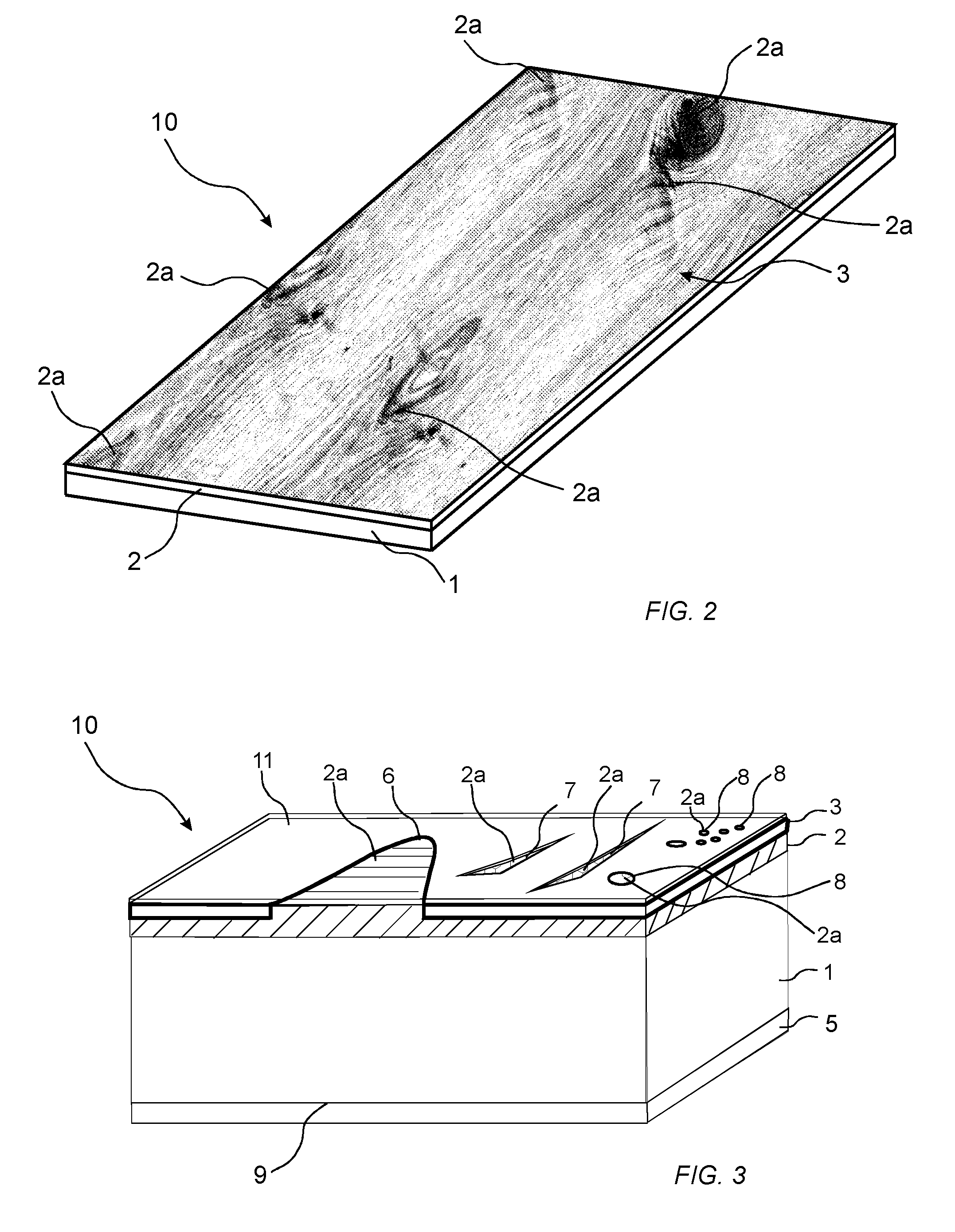
FIG. 2 illustrates an embodiment of a veneered element.
FIG. 3 illustrates a cross-section of a veneered element.
FIG. 4 illustrates an embodiment of a veneered element.
FIG. 5 illustrates an embodiment of a veneered element.
DETAILED DESCRIPTION
FIGS. 1a-c show embodiments of a method of producing a veneered element 10. The veneered element 10 may be a furniture component, a building panel such as a floor panel, a ceiling panel, a wall panel, a door panel, a worktop, skirting boards, mouldings, edging profiles, etc. The method comprises providing a substrate 1. The substrate is preferably a pre-fabricated substrate, manufactured prior to the method of producing the veneered element 10. The substrate 1 may be a board, for example, a wood-based board as shown in the embodiment shown in FIGS. 1-4. The wood-based board may be a wood fibre based board such as MDF, HDF, particleboard etc., or a plywood board. In other embodiments, the substrate may be a Wood Plastic Composite (WPC). The substrate may be a mineral composite board. The substrate may be a fibre cement board. The substrate may be magnesium oxide cement board. The substrate may be a ceramic board. The substrate may be a plastic board such as a thermoplastic board. In another embodiment, the substrate 1 may be a carrier such as sheet of paper or non-woven as shown in FIG. 5, or a conveyor.
A sub-layer 2 is applied on a first surface 4 of the substrate 1. In the embodiment shown in FIG. 1a, the sub-layer 2 is applied in powder form 21. The powder 21 adapted to form the sub-layer 2 is applied by scattering, as shown in FIG. 1a. The sub-layer may also be applied as granules. In other embodiments, the sub-layer 2 may be applied as a liquid, as a paste, a sheet, etc. The sub-layer 2 may be applied by roller coating, spraying, etc.
In one embodiment, the sub-layer 2 comprises a sheet impregnated with a thermosetting binder. The sheet may be paper sheet. The sheet may be coloured, and/or the binder solution used to impregnate the sheet may be coloured, such that sheet becomes coloured during impregnation.
The sub-layer 2 comprises a binder. The binder may be a thermosetting binder, a thermoplastic binder, or a combination thereof. The binder may be wood mastic, wood filler or any other type of putty-like paste. The thermosetting binder may be an amino resin such as melamine formaldehyde resin, phenol formaldehyde resin, urea formaldehyde resin, or a combination thereof. Urea formaldehyde resin may be used, alone or in combination with melamine formaldehyde resin, to reduce tension formed by the sub-layer 2 during curing, compared to when melamine formaldehyde resin is used only. The thermoplastic binder may be polyvinyl chloride (PVC), polyethylene (PE), polypropylene (PP), polyurethane (PU), polyvinyl alcohol (PVOH), polyvinyl butyral (PVB), polyvinyl acetate (PVAc), and/or thermoplastic elastomer (TPE), or a combination thereof.
The binder may be in powder form when applied.
The sub-layer 2 may be formed of a mix comprises a binder of the above described type and fillers. The mix may further comprise pigments. The mix may further comprise additives. The mix may further comprise wear and/or scratch resistant particles. As an alternative to a mix, the binder, fillers, pigments, additives and any other component may be applied separately on the substrate 1.
The fillers may be particles or fibres, for example wood fibres or particles, or mineral particles or fibres. The wood particles may be lignocellulosic particles and/or cellulosic particles. The wood particles may be at least partially bleached. The fillers may be rice, straw, corn, jute, linen, flax, cotton, hemp, bamboo, bagasse or sisal particles or fibres. The sub-layer may comprise starch such as maize starch, potato starch, etc.
The fillers may be fillers having sound-absorbing properties such as cork particles and/or barium sulphate (BaSO4). Alternatively, a sound-absorbing layer, for example a cork layer or cork veneer layer, may be arranged as an intermediate layer. The sub-layer is applied on the sound-absorbing layer. The sound-absorbing layer may be arranged on the substrate, or on a sub-layer arranged on the substrate.
The pigments may be darker than the natural colour of the veneer layer, and/or be paler that the natural colour of the veneer layer. The pigments may include white pigments such as TiO2. A pigment such as TiO2 can combined with at least partially bleached wood particles to obtain a white staining of the veneer by the permeation of the sub-layer through the veneer. In one embodiment, a pre-mix is formed by white pigments such as TiO2 and wood particles, preferably at least partially bleached wood particles. The pre-mix is then mixed with remaining wood particles, binder, additives etc.
The additives may be wetting agents, anti-static agents such as carbon black, and heat-conducting additives such as aluminium. Other possible additives are magnetic substances.
The sub-layer 2 may also comprise a foil or a sheet.
Additives such as blowing agents may be included in the sub-layer. The blowing agents may be physical foaming agents such as EXPANCEL.RTM. and/or chemical blowing agents such as AIBN (azoisobutyronitrile) or ADC (azodicarbonamide).
The wear and/or scratch resistant particles may be aluminium oxide particles and/or silica particles.
In one embodiment, the sub-layer 2 consists essentially of the binder and optionally additives, meaning that at least 90% of the sub-layer 2 is the binder and optional additive(s). In one embodiment, the sub-layer 2 is free from any fibres and/or fillers.
The sub-layer 2 may be applied in an amount of 200-600 g/m2, preferably 300-500 g/m2 such as about 400 g/m2. The amount of binder applied for the sub-layer 2 may be 100-300 g/m2, preferably 150-250 g/m2 such as about 200 g/m2. The sub-layer 2 may comprise the binder in an amount of 30-80 wt %, preferably in an amount of 40-60 wt % such as about 50 wt %.
The sub-layer 2 may be pre-pressed prior to applying the veneer layer 3.
A veneer layer 3 is applied on the sub-layer 2. The veneer layer 3 may be a wood veneer, a cork veneer, or a stone veneer. The veneer has a porous structure, thus being permeable. The veneer layer 3 may have a thickness of about 0.2 to 1 mm. The veneer layer 3 may be continuous or non-continuous. The veneer layer 3 may be formed of several veneer pieces. The veneer pieces may be over-lapping or non-overlapping. A gap may be formed between the veneer pieces. The gap may be filled by the sub-layer 2 after pressing. The veneer pieces may be applied randomly or forming a pattern. A patchwork of veneer pieces may be formed. The veneer pieces may be arranged in a pattern such as a herringbone pattern, Dutch pattern etc., with several veneer pieces arranged on one substrate 1. The veneer pieces may also be arranged such that the veneer pieces, or the gap between the veneer pieces, forma template.
The sub-layer 2 may have a uniform colour, different shades, or different portions of the sub-layer may have different colours. A multi-coloured veneer layer 3 may be formed by colouring different portions of the sub-layer 2 in different colours. If the veneer layer 3 is formed by several veneer pieces, a first set of veneer pieces may be differently coloured than a second set of veneer pieces. Alternatively, each veneer piece may be differently coloured by the sub-layer being differently coloured under each veneer piece.
In one embodiment, a digital print may be printed in the sub-layer 2, preferably by an ink jet printer. The different colours of the print permeate through the veneer layer 3 such that the colouring of the sub-layer 2 is transferred into the surface of the veneer layer 3. The colouring and/or pattern of the sub-layer 2 may also be obtained by a binder and print technique (BAP), for example as described in WO2014/017972. In one embodiment, a digital print is printed on the veneer layer 3.
More than one veneer layer 3 may be arranged on a core. In one embodiment, a first veneer layer may be arranged on the substrate 1, a sub-layer 2 of the above described type is arranged on the first veneer layer, and a second veneer layer is arranged on the sub-layer 2. A groove may be formed, for example after pressing, in the second veneer layer and in the sub-layer 2 such as the first veneer layer is visible. A gap may also be arranged between different portions of the second veneer layer such that the sub-layer and/or the first veneer layer is visible. The veneer layer may also comprise veneer pieces arranged crosswise.
In the embodiment shown in FIG. 1b, a protective layer 11 is arranged on the veneer layer 3. The protective layer 11 comprises a thermoplastic material. After the protective layer 11 has been arranged on the veneer layer 3, pressure is applied to the veneer layer 3, via the protective layer 11, and/or the substrate 1 such that a fluid pressure is formed in the sub-layer 2. The pressure may be applied by continuous press 30 or in a discontinuous press (not shown). Preferably, heat is also applied. The gloss level of the protective layer may be determined and changed by the press plate or press belt when pressing the protective layer to the veneer layer. Different gloss levels may be obtained by a pressing device having different gloss. The pressing device may also comprise embossed portion such that a structured protective layer 11 is obtained.
In the embodiment shown in FIG. 1c, pressure is applied to the veneer layer 3 and/or the substrate 1 such that a fluid pressure is formed in the sub-layer 2. The pressure may be applied by continuous press 30 or in a discontinuous press (not shown). Preferably, heat is also applied. In a subsequent step, a protective layer 11 is applied to the veneer layer 3. The protective layer 11 comprises a thermoplastic material. The protective layer 11 may be attached to the veneer layer 3 by any conventional means, such as pressing, gluing etc. In the embodiment shown in FIG. 1c, pressure is applied to the protective layer 11 and/or the substrate 1 in a continuous press 31 for attaching the protective layer 11 to the veneer layer 3. The pressure may also be applied in a static press (not shown). The gloss level of the protective layer may be determined and changed by the press plate or press belt when pressing the protective layer to the veneer layer. Different gloss levels may be obtained by a pressing device having different gloss. The pressing device may also comprise embossed portion such that a structured protective layer 11 is obtained.
The protective layer may also be attached to at least a portion of an edge surface of the substrate, for example, a bevel formed along an edge of the substrate. Thereby, also an edge portion of the substrate is protected by the protective layer such that the water resistance of the veneered element is further improved. For example, the width of the protective layer applied may exceed the width of the substrate, such that the protective layer can be bent over the edge of the substrate and attached to an edge portion of the substrate.
Prior to applying the protective layer 11, the veneer layer may be treated in different ways. For example, the veneer layer 3 may be brushed after pressing. The veneer layer 3 may be mechanically and/or chemically treated after pressing.
In both the embodiment shown in FIGS. 1b and in FIG. 1c, the protective layer 11 is in form of a thermoplastic foil. The thermoplastic foil comprises a thermoplastic material. The thermoplastic material may comprise polyvinyl chloride (PVC), polyester, polypropylene (PP), polyethylene (PE), polystyrene (PS), polyurethane (PU), polyethylene terephthalate (PET), polyacrylate, methacrylate, polycarbonate, polyvinyl butyral, polybutylene terephthalate, or a combination thereof. The thermoplastic foil may comprise one or several layers. The layers may comprise the same thermoplastic material, or different thermoplastic materials. In one embodiment, the protective layer 11 comprises applying a first foil comprising a first thermoplastic material, preferably polyvinylchloride (PVC), on the veneer layer (3), and applying a second foil comprising a second thermoplastic material, preferably polyurethane (PU), on the first foil.
The thermoplastic foil may be provided as a continuous web, as shown in FIGS. 1b and 1c. The thermoplastic foil may be provided as sheets.
The protective layer 11 may comprise wear resistant particles. The wear resistant particles may be applied on the veneer layer 3 prior to apply the thermoplastic foil. The wear resistant particles may be applied between two different layers of the protective layer 11. The wear resistant particles may be applied on the protective layer 11. The wear resistant particles may be aluminium oxide particles such as aluminium. Alternatively, or as a complement, the wear resistant particles may be carborundum, quartz, silica, glass, glass beads, glass spheres, silicon carbide, diamond particles, hard plastics, reinforced polymers and organics. The wear resistant particles preferably have a size of 10-200 .mu.m, preferably 50-100 .mu.m. The wear resistant particles may have an irregular shape. The refractive index of the wear resistant particles 4 may be 1.4-1.7.
Also scratch resistant particles may be applied in a similar manner.
In an embodiment (not shown), the protective layer 11 is applied by applying a thermoplastic material in powder form on the veneer layer 3. The thermoplastic material may comprise polyvinyl chloride (PVC), polyester, polypropylene (PP), polyethylene (PE), polystyrene (PS), polyurethane (PU), polyethylene terephthalate (PET), polyacrylate, methacrylate, polycarbonate, polyvinyl butyral, polybutylene terephthalate, or a combination thereof. The protective layer may be applied as one or several layers, comprising the same thermoplastic material, or different thermoplastic materials. As described above, the protective layer 11 formed by a thermoplastic material in powder form may be applied, both prior to, and after, pressure has been applied to the veneer layer 3 and/or the substrate 1.
Wear resistant particles of the above described type may be applied together with the thermoplastic powder, preferably as mix comprising the thermoplastic material and the wear resistant particles. The mix may further comprise scratch resistant particles. Alternatively, or as a complement, wear resistant particles may be applied on the veneer layer 3, prior to applying the thermoplastic material in powder form, or after the thermoplastic material in powder form has been applied.
In other embodiments, the protective layer 11 comprising a thermoplastic material of the above described type may be applied in form of a slurry and/or paste on the veneer layer 3.
When sufficient pressure is applied as in the embodiment shown in FIG. 1b or in the embodiment shown in FIG. 1c, the sub-layer 2 permeates through pores, cracks and holes in the veneer layer 3. At least a portion of the sub-layer 2 permeates fully through the veneer layer 3 such that said at least a portion of the sub-layer 2 becomes visible on the veneer layer 3. Said at least a portion of the sub-layer, which permeates or transfers through the veneer layer 3, comprises at least one component of the sub-layer 2. The matter of the sub-layer 2 permeating through the veneer layer 3 may be one or several of the components of the sub-layer 2. For example, the binder of the sub-layer 2 may permeate through the veneer layer. The binder may bring any pigments of the sub-layer 2 to the upper surface of the veneer layer 3 when melted during pressing.
The sub-layer 2 may be in fluid form or powder form when applied. The binder of the sub-layer 2, for example a thermosetting or thermoplastic binder, may be applied as a powder or in fluid form as a dispersion, solution or suspension. If the binder is applied in powder form when applied, the binder melts when applying heat exceeding the melting point of the binder at the pressure applied. Thereby, the binder is in liquid form. By applying a pressure, a fluid pressure of the sub-layer 2 is formed. Thereby, the binder in liquid form may permeate the veneer layer 3. If a thermosetting binder is used, the thermosetting binder is firstly dominated by a melting process up to a first temperature, thereafter the thermosetting binder is dominating by a crosslinking process.
By controlling the degree of permeation of the sub-layer 2 through the veneer layer 3, the design of the veneered element 10 can be controlled. The design of the veneer can be changed by the sub-layer 2 at least partly permeating the veneer layer 3 and thus being visible at the surface of the veneer layer 3. If the veneer layer 3 comprises cracks, cavities and other irregularities, the fluid pressure required to permeate completely through the veneer layer 3 is decreased, such that portions of the sub-layer 2 easily permeates through the veneer layer 3 and fills the crack or holes. Thereby, putty can be avoided or at least reduced. By including pigments in the sub-layer 2, the design of the veneer can be changed further.
For some designs, a large degree of permeation may be desired, and for other designs, less, or varying, permeation may be desired. For example, if a uniform colouring of the veneer such as glazing, lazuring or staining is desired, a uniform fluid pressure is preferred. Preferably, the veneer layer 3 has a uniform thickness and structure. If a varying permeation is desired, resulting in varying pattern of the veneer, a varying fluid pressure is preferred. The veneer layer 3 may have a varying structure including cracks and cavities. The thickness of the veneer layer 3 can also be controlled in order to control the permeation of the sub-layer 2 and thereby the design of the veneer layer 3. The thinner the veneer layer 3 is, the larger amount of the sub-layer 2 permeates through the veneer layer 3.
Controlling the design of the veneered element 10 by controlling the permeation of the sub-layer 2 can be made in several ways. The fluid pressure may be controlled and adjusted. The fluid pressure may be varying over the surface of the veneer layer 3. The fluid pressure can be increased if a large degree of permeation of the sub-layer 2 is desired. The fluid pressure can be decreased if less permeation of the sub-layer 2 is desired.
The fluid pressure can be controlled in several ways. The fluid pressure can be controlled by controlling the pressure applied to the substrate 2 and/or veneer layer 3. The temperature applied may have influence on the permeation, for example by changing the viscosity of the sub-layer 2.
The fluid pressure may also be controlled by generating a gas pressure in the sub-layer 2. By generating a gas pressure inside the sub-layer 2, the fluid pressure increases. The gas pressure may be generated by including chemical and/or physical blowing agents in the sub-layer. The chemical and/or physical blowing agents increase the fluid pressure when activated.
The fluid pressure of the sub-layer 2 may also be controlled by adjusting the concentration of binder in the sub-layer 2. By increasing the concentration of the binder of the sub-layer 2, the more material of the sub-layer 2 may permeate through the veneer layer 3. The part of the sub-layer 2 that flows when heat and pressure is applied increases, and thereby a larger part of the sub-layer 2 may permeate through the veneer layer 3. Furthermore, the type of binder may be adjusted. By increasing the amount of a thermosetting binder in the sub-layer 2, the part of the sub-layer 2 being flowable when heat and pressure is applied increases, and thereby the fluid pressure.
The fluid pressure of the sub-layer 2 may also be controlled by adjusting the type of binder in the sub-layer 2. By using different type of binders, the fluid pressure of the sub-layer 2 and thereby the permeation can be altered. A rapidly curing binder forms less permeation of the sub-layer 2 through the veneer layer. The fluid pressure may also be controlled by adjusting the formulation of the binder of the sub-layer. Thereby, properties of the sub-layer can be controlled.
The fluid pressure may also be controlled by adjusting the moisture content of the sub-layer. The higher moisture content of the sub-layer, the more steam is formed when applying heat and pressure, thereby increasing the fluid pressure, and consequently, permeation of the sub-layer 2 through the veneer layer 3. Contrary, by decreasing the moisture content of the sub-layer 2 before pressing, for example, by drying the sub-layer 2, the less steam is formed during pressing.
Permeation of the sub-layer 2 through the veneer layer 3 may also be controlled by including fillers in the sub-layer. The fillers reduce permeation of the sub-layer by reducing the flowing of the binder. Some fillers, such as wood particles and other organic fillers, absorb the binder to some extent such that the remaining binder that is free to permeate through the veneer layer 3 is reduced. The fluid pressure is thereby also reduced.
Permeation of the sub-layer 2 through the veneer layer 3 may also be controlled by adjusting the thickness of the sub-layer 2, for example by adjusting the amount of sub-layer applied. If the sub-layer 2 is applied as a powder, the amount of powder applied can be adjusted in order to achieve the desired permeation of the sub-layer 2 through the veneer layer 3. The thicker sub-layer, i.e. the larger amount of sub-layer applied, the more the sub-layer 2 permeates through the veneer layer 3.
Permeation of the sub-layer 2 through the veneer layer 3 may also be controlled by forming holes or cracks through the veneer layer 3. By forming, or enlarging existing, holes and cracks, the sub-layer 2 permeates easily through the veneer layer 3. Controlling permeation of the sub-layer 2 through the veneer layer 3 may be performed by forming, or enlarging existing cavities, holes and/or cracks, preferably by brushing.
By adjusting and controlling these parameters, permeation of the sub-layer 2 through the veneer layer 3 can be controlled such that a desired look of the veneer surface is obtained, for example as shown in FIGS. 2-5.
In an embodiment, a produced building panel may be 6-25 mm thick, preferably 8-15 mm thick after pressing, while the core may be 5-22 mm thick, preferably 7-14 mm thick. The sub-layer may be 0.1-2 mm thick after pressing.
Furthermore, a protective layer may be applied to the veneer layer 3. The protective layer may be a coating such as one or several lacquer layers. The coating may be an acrylate or methacrylate coating such as polyurethane coating. The coating may comprise wear and/or scratch resistant particles. The protective layer may be an overlay paper comprising wear resistant particles. The protective layer may be a powder overlay, as described in WO2011/129755, comprising processed wood fibres, a binder and wear resistant particles applied as mix on the veneer surface. If the protective layer comprises or is an overlay paper or a powder overlay, the protective layer is preferably applied before the step of applying heat and pressure. Thereby, the protective layer is cured and attached to the veneer layer in the same step as attaching the veneer layer to the sub-layer and to the substrate.
The veneered element 10 may further be treated in different ways, for example brushed, oiled, lacquered, waxed, etc. After pressure has been applied, the veneer layer 3 may be mechanically/and or chemically treated such that a desired appearance of the veneered element 10 is obtained. For examples, the veneer layer 3 may be brushed and/or sanded after pressing.
A protective coating may also be applied to the veneer layer 3 prior to pressing. In one embodiment, a wax powder is applied, for example, scattered, on the upper surface of the veneer layer, facing away from the substrate 1, prior to pressing. During pressing, the wax powder forms a protective coating of the veneered element 10.
In one embodiment, a primer is applied on the upper surface of the veneer layer, facing away from the substrate 1, prior to pressing. The primer may be a print primer, a primer for preparing the veneer layer 3 for lacquering, etc.
A protective foil may also be applied on the veneer layer 3 prior or after pressing. The protective foil may be thermoplastic foil such as PU or PVC foil, as described above with reference to FIGS. 1b and 1c.
In the embodiment in FIGS. 1-4, the substrate 1 comprises a wood-based board such as plywood, HDF, MDF, particleboard etc. In this embodiment the veneered element 10 may be a building panel or a furniture component. If the veneered element 10 is a floor or wall panel, the floor or wall panel may be provided with a mechanical locking system for joining with an adjacent floor or wall panel. The mechanical locking system may be any of the types disclosed in WO 2007/015669, WO 2008/004960, WO 2009/116926, or WO 2010/087752. If the veneered element 10 is a furniture component for a drawer, shelf or other furniture, the furniture may be provided with a mechanical locking system for joining with another part of the drawer, shelf or furniture component. The mechanical locking system may be of the type described in WO 2012/154113.
The veneered element 10 may be provided with decorative grooves or bevels. The decorative grooves or bevels may be extending into the sub-layer 2 such that the sub-layer 2 is visible form the top surface of the veneered element. The decorative groove or bevel may be arranged adjacent an edge of the veneered element provided with the mechanical locking system. By providing a decorative groove extending into the sub-layer 2, a ship-decking appearance may be obtained.
In the embodiment in FIG. 2, the sub-layer 2 has permeated through the veneer layer 3 in some portions of the veneer layer 3 where the resistance of the veneer has been lower, for example as in cracks, holes and cavities of the veneer layer, but to a lower degree through other parts of the veneer layer 3. Portions 2a of the sub-layer 2 are visible on the surface of the veneer layer 3 as shown in FIG. 2. The permeation of the sub-layer 2 forms an irregular design of the veneer.
FIG. 3 shows a cross-section of the veneered element 10 in more detail. FIG. 3 illustrates in more detail how portions 2a of the sub-layer 2 have permeated through the veneer layer 3 such that the portions 2a of the sub-layer 2 are visible from an exposed surface of the veneer layer 3. FIG. 3 illustrates that the sub-layer 2 has permeated through the veneer layer 3 and filled holes 6 of veneer such that portions 2a of the sub-layer 2 are visible through the veneer layer 3. The hole 6 may, as in FIG. 3, be a knot. FIG. 3 also illustrates that the sub-layer 2 has permeated through the veneer layer 3 and filled cracks 7 in the veneer such that portions 2a of the veneer layer 3 are visible from the upper surface of the veneer layer 3. Furthermore, FIG. 3 shows that portions 2a of the sub-layer 2 have permeated through pores 8 of the veneer layer 3 such that portions 2a of the sub-layer 2 are visible on the upper surface of the veneer layer 3. In the embodiment shown in FIG. 3, the substrate 1 comprises a wood based board such as plywood, HDF, MDF, particleboard etc. The veneered element 10 is also provided with a balancing layer 5 arranged on a second surface 9 of the substrate 1, opposite the sub-layer 2. The balancing layer 5 may be a powder based balancing layer being applied as a powder. The powder based balancing layer may comprise wood particles such as lignocellulosic and/or cellulosic particles and a binder, preferably a thermosetting binder such as an amino resin. The balancing layer may be a resin impregnated paper, preferably impregnated with a thermosetting binder. The substrate 1 is also provided with a protective layer 11. The protective layer 11 may, for example, be a coating as described above or a protective layer comprising a thermoplastic material as described above with reference to FIGS. 1b and 1c.
In FIG. 4, also showing a veneered element 10 of the above described type wherein the substrate 1 comprising a wood based board such as plywood, HDF, MDF, particleboard etc. Also in this embodiment the veneered element 10 may be a building panel or a furniture component, and may be provided with a mechanical locking system. However, in this embodiment, compared to the embodiment shown in FIG. 2, permeation of the sub-layer 2 is more uniform through the veneer layer 3 such that a more regular design of the veneer layer 3 is obtained. This may be achieved by applying a uniform pressure, and by providing a veneer layer 3 having a uniform porous structure and/or uniform thickness.
FIG. 5 shows an embodiment of the veneered element 10 of the above described type wherein the substrate 1 comprises a paper or a sheet. The substrate 1 forms a carrier for the veneer layer 3 and the sub-layer 2. The veneered element 10 according to this embodiment may be bendable and/or flexible. Thereby, post-forming of the veneered element 10 is possible. The veneered element 10 may be adhered to another element in a later operation. The veneered element 10 may form a surface of, for example, a furniture component. In one embodiment, the substrate is a conveyor, and the veneered element 10 is removed from the conveyor after heat and pressure have been applied.
It is contemplated that there are numerous modifications of the embodiments described herein, which are still within the scope of the invention as defined by the appended claims.
It is contemplated that the sub-layer may not directly contact the substrate, but an intermediate layer arranged between the substrate and the sub-layer may be provided.
It is also contemplated that the building panel may be provided with a second veneer layer (not shown) of the above described type applied in the same manner as described above. A sub-layer of the above described type is applied on a second surface of the substrate of the above described type. The second surface of the core faces away from the veneer layer described above with reference to FIGS. 1-4. In this embodiment, the veneer layer described above with reference to FIGS. 1-4 is considered as a first veneer layer, and the second veneer layer is arranged oppositely the first veneer layer. A design of the second veneer layer is controlled by determining level of permeation of the sub-layer through the second veneer layer as described above with reference to FIGS. 1-5.
EXAMPLES
Example 1
400 g/m2 of a powder mixture, comprising 40 wt-% wood fibres, 10 wt-% aluminium oxide (Alodur ZWSK 180-ST), 49.5 wt-% melamine formaldehyde resin (Kauramin 773) and 0.5 wt-% of carbon black (Printex 60), was scattered on a 10.0 mm HDF board for forming a sub-layer. The powder layer forming the sub-layer was sprayed with 20 g/m2 of an aqueous solution of a release agent (PAT-660). A 0.6 mm oak veneer layer was positioned on the sub-layer prior to pressing the assembly in a short cycle press for 30 seconds at 40 bar with a press plate temperature of 160.degree. C. The resulting product was a veneered HDF having pores and cracks in the veneer layer filled with the cured powder mixture of the sub-layer.
Example 2
800 g/m2 of a powder mixture, comprising of 40 wt-% wood fibres, 10 wt-% aluminium oxide (Alodur ZWSK 180-ST), 49.5 wt-% melamine formaldehyde resin (Kauramin 773) and 0.5 wt-% of carbon black (Printex 60), was scattered on a 10.0 mm HDF board for forming a sub-layer. The powder layer forming the sub-layer was sprayed with 20 g/m2 of an aqueous solution of a release agent (PAT-660). A 0.6 mm oak veneer was positioned on the sub-layer prior to pressing the assembly in a short cycle press for 30 seconds at 40 bar with a press plate temperature of 160.degree. C. The resulting product was a veneered HDF having cracks and an increased amount of pores in the veneer layer filled with the cured powder mixture of the sub-layer in comparison with the product of example 1.
Example 3
400 g/m2 of a powder mixture, comprising 17.5 wt-% wood fibres, 17.5 wt-% mineral fibres 10 wt-% aluminium oxide (Alodur ZWSK 180-ST), 52.5 wt-% melamine formaldehyde resin (Kauramin 773) and 0.5 wt-% of carbon black (Printex 60), was scattered on a 10.0 mm HDF board for forming a sub-layer. The powder layer forming the sub-layer was sprayed with 20 g/m2 of an aqueous solution of a release agent (PAT-660). A 0.6 mm oak veneer was positioned on the sub-layer prior to pressing the assembly in a short cycle press for 30 seconds at 40 bar with a press plate temperature of 160.degree. C. The resulting product was a veneered HDF having cracks and a decreased amount of pores in the veneer layer filled with the cured powder mixture of the sub-layer in comparison with the product of example 1.
Example 4
400 g/m2 of a powder mixture, comprising 10 wt-% aluminium oxide (Alodur ZWSK 180-ST), 89.5 wt-% melamine formaldehyde resin (Kauramin 773) and 0.5 wt-% of carbon black (Printex 60), was scattered on a 10.0 mm HDF board for forming a sub-layer. The powder layer forming the sub-layer was sprayed with 20 g/m2 of an aqueous solution of a release agent (PAT-660). A 0.6 mm oak veneer was positioned on the sub-layer prior to pressing the assembly in a short cycle press for 30 seconds at 40 bar with a press plate temperature of 160.degree. C. The resulting product was a veneered HDF having cracks and an increased amount of pores in the veneer filled with the cured powder mixture of the sub-layer in comparison with the product of the example 1.
Example 5
400 g/m2 of a powder mixture, comprising 40 wt-% wood fibres, 10 wt-% aluminium oxide (Alodur ZWSK 180-ST), 49.5 wt-% thermoplastic binder (Vinnapas 5010 N) and 0.5 wt-% of carbon black (Printex 60), was scattered on a 10.0 mm HDF board for forming a sub-layer. The powder layer forming the sub-layer was sprayed with 20 g/m2 of an aqueous solution of a release agent (PAT-660). A 0.6 mm oak veneer was positioned on the sub-layer prior to pressing the assembly in a short cycle press for 30 seconds at 40 bar with a press plate temperature of 160.degree. C. The resulting product was a veneered HDF having a decreased amount of pores and cracks in the veneer layer filled with the cured powder mixture compared to the product of example 1.
Example 6
400 g/m2 of a liquid mixture, comprising 45 wt-% water, 10 wt-% aluminium oxide (Alodur ZWSK 180-ST), 44.5 wt-% melamine formaldehyde resin (Kauramin 773) and 0.5 wt-% of carbon black (Printex 60), was applied on a 10.0 mm HDF board for forming a sub-layer. A 0.6 mm oak veneer was positioned on the liquid layer forming the sub-layer prior to pressing the assembly in a short cycle press for 30 seconds at 40 bar with a press plate temperature of 160.degree. C. The resulting product was a veneered HDF having pores and cracks in the veneer layer filled with the cured mixture.
Example 7
200 g/m2 of a polyurethane powder (Desmomelt VP KA 8702) was applied on a 10.0 mm HDF board for forming a sub-layer. A 0.6 mm oak veneer was positioned on the sub-layer prior to pressing. Wear resistant particles in form of 40 g/m2 of aluminium oxide (Alodur ZWSK 180-ST) were applied on the oak veneer prior to pressing. Further, a 0.05 mm polyurethane film (LPT 4802) was applied on the oak veneer with the wear resistant particles prior to pressing. The assembly was pressed in a short cycle press for 40 seconds at 20 bar with a temperature of 140.degree. C. and thereafter cooled to 50.degree. C. The resulting product was a veneered HDF having pores and cracks in the veneer layer filled with the sub-layer. The veneer layer was protected by the polyurethane film.
Example 8
210 g/m2 of a powder mix comprising 44 wt % wood fibre, 46 wt % phenol-formaldehyde resin (Prefere 4976), 5 wt % titanium dioxide and 5 wt % aluminium oxide (Alodur ZWSK 180 ST-180) was applied on a 10.0 mm HDF board for forming a sub-layer. A 0.6 mm oak veneer was applied on the sub-layer prior to pressing. A 0.05 mm polyurethane film (LPT4802) was applied on the oak veneer prior to pressing. The assembly was pressed in a short cycle press for 40 seconds at 20 bar with a temperature of 140.degree. C. and thereafter cooled to 50.degree. C. The resulting product was a veneered HDF having pores and cracks in the veneer layer filled with the cured sub-layer. The veneer layer was protected by the polyurethane film.
Example 9
300 g/m2 of a powder mix comprising 30.41 wt % wood fibre, 52.5 wt % melamine-formaldehyde resin (Kauramin 773), 3.4 wt % titanium dioxide, 8.8 wt % aluminium oxide (Alodur ZWSK 180-ST), 4.7 wt % pigment Lichtgrau G10512, 0.15 wt % pigment Gelb 265 and 0.04 wt % pigment carbon black (Black 920) was applied on a 10.0 mm HDF board for forming a sub-layer. A 0.06 mm oak veneer was applied on the sub-layer prior to pressing. A 0.05 mm polyurethane film (LPT 4802) was applied on the veneer prior to pressing. The assembly was pressed in a short cycle press for 120 seconds at 20 bar and a temperature of 160.degree. C. The resulting product was a veneered HDF having pores and cracks in the veneer layer filled with the cured sub-layer. The veneer layer was protected by the polyurethane film.
Example 10
40 g/m2 of a polyurethane powder (Desmomelt VP KA 8702) was applied on a 10.0 mm HDF board for forming a sub-layer. A 0.9 mm cork veneer was applied on the sub-layer prior to pressing. Wear resistant particles in form of 40 g/m2 aluminium oxide (Alodur ZWSK 180-ST) were applied on the cork veneer prior to pressing. A 0.05 mm polyurethane film (LPT 4802) was applied on the cork veneer and the wear resistant particles prior to pressing. The assembly was pressed in a short cycle press for 40 seconds at 20 bar with a temperature of 140.degree. C. and thereafter cooled to 50.degree. C. The resulting product was a veneered HDF having pores and cracks in the veneer layer filled with the sub-layer. The veneer layer was protected by the polyurethane film.
Example 11
40 g/m2 of a polyurethane powder (Desmomelt VP KA 8702) was applied on a 10.0 mm HDF board for forming a sub-layer. A 0.9 mm cork veneer was applied on the sub-layer prior to pressing. A first 0.05 mm polyurethane film (LPT 4802) was applied on the cork veneer. Wear resistant particles in form of 40 g/m2 aluminium oxide (Alodur ZWSK 180-ST) were applied on the cork veneer prior to pressing. A second 0.05 mm polyurethane film (LPT 4802) was applied on the first polyurethane film and the wear resistant particles prior to pressing. The assembly was pressed in a short cycle press for 40 seconds at 20 bar with a temperature of 140.degree. C. and thereafter cooled to 50.degree. C. The resulting product was a veneered HDF having pores and cracks in the veneer layer filled with the sub-layer. The veneer layer was protected by the polyurethane film.
* * * * *
References
D00001
D00002
D00003
XML
uspto.report is an independent third-party trademark research tool that is not affiliated, endorsed, or sponsored by the United States Patent and Trademark Office (USPTO) or any other governmental organization. The information provided by uspto.report is based on publicly available data at the time of writing and is intended for informational purposes only.
While we strive to provide accurate and up-to-date information, we do not guarantee the accuracy, completeness, reliability, or suitability of the information displayed on this site. The use of this site is at your own risk. Any reliance you place on such information is therefore strictly at your own risk.
All official trademark data, including owner information, should be verified by visiting the official USPTO website at www.uspto.gov. This site is not intended to replace professional legal advice and should not be used as a substitute for consulting with a legal professional who is knowledgeable about trademark law.