Thread die retaining method and apparatus
Steinfels , et al.
U.S. patent number 10,279,410 [Application Number 15/316,385] was granted by the patent office on 2019-05-07 for thread die retaining method and apparatus. This patent grant is currently assigned to Stanley Black & Decker, Inc.. The grantee listed for this patent is STANLEY BLACK & DECKER, INC.. Invention is credited to Ian E. Random, Craig R. Steinfels.


| United States Patent | 10,279,410 |
| Steinfels , et al. | May 7, 2019 |
Thread die retaining method and apparatus
Abstract
A retaining socket for receiving a thread die includes a plunge component that is moveable along the longitudinal axis of the retaining socket and at least one pin extending parallel to the longitudinal axis configured to engage the thread die.
| Inventors: | Steinfels; Craig R. (Powell, OH), Random; Ian E. (Muskego, WI) | ||||||||||
|---|---|---|---|---|---|---|---|---|---|---|---|
| Applicant: |
|
||||||||||
| Assignee: | Stanley Black & Decker,
Inc. (New Britain, CT) |
||||||||||
| Family ID: | 54767307 | ||||||||||
| Appl. No.: | 15/316,385 | ||||||||||
| Filed: | June 3, 2015 | ||||||||||
| PCT Filed: | June 03, 2015 | ||||||||||
| PCT No.: | PCT/US2015/033934 | ||||||||||
| 371(c)(1),(2),(4) Date: | December 06, 2016 | ||||||||||
| PCT Pub. No.: | WO2015/187798 | ||||||||||
| PCT Pub. Date: | December 10, 2015 |
Prior Publication Data
| Document Identifier | Publication Date | |
|---|---|---|
| US 20180147644 A1 | May 31, 2018 | |
Related U.S. Patent Documents
| Application Number | Filing Date | Patent Number | Issue Date | ||
|---|---|---|---|---|---|
| 62007475 | Jun 4, 2014 | ||||
| Current U.S. Class: | 1/1 |
| Current CPC Class: | B23G 1/30 (20130101); B23G 1/261 (20130101); Y10T 279/3481 (20150115) |
| Current International Class: | B23G 1/30 (20060101); B23G 1/26 (20060101) |
| Field of Search: | ;470/207 |
References Cited [Referenced By]
U.S. Patent Documents
| 1285866 | November 1918 | Wilson |
| 1450211 | April 1923 | Kopp |
| 1571515 | February 1926 | Fleming |
| 2273598 | February 1942 | Shafer |
| 2349400 | May 1944 | Beckwith |
| 2417813 | March 1947 | Curtis |
| 2433058 | December 1947 | Mesaros |
| 2855614 | October 1958 | Simon |
| 3715168 | February 1973 | Kuhn |
| 4095917 | June 1978 | Wesner |
| 4856946 | August 1989 | Park |
| 7736100 | June 2010 | Evans |
Attorney, Agent or Firm: Drayton; Caeden Ayala; Adan
Claims
The invention claimed is:
1. A retaining socket for receiving a thread die comprising: a body including a longitudinal axis, a handle engaging portion and a thread die receiving cavity; and a plunge component including an annular disc having a central aperture, the plunge component being moveable along the longitudinal axis, and at least one pin extending parallel to the longitudinal axis from the annular disc into the cavity, the at least one pin being configured to engage the thread die.
2. The retaining socket of claim 1 further comprising means for retaining the thread die in the body.
3. The retaining socket of claim 2 wherein the means for retaining includes a magnetic washer.
4. A socket for receiving a thread die comprising: a body including a cavity configured to receive a thread die; a plunge component coupled to the body, wherein the plunge component includes at least one pin and a pair of arms, the at least one pin being disposed in the body to engage the thread die in response to movement of the arms; and means coupled to the body for retaining the thread die in the cavity.
5. The retaining socket of claim 4 wherein the means for retaining includes a magnetic washer.
6. A socket for receiving a thread die comprising: a body including a thread die receiving socket; means coupled to the adaptor body for retaining the thread die in the socket; and a plunge component including a plurality of pins for engaging the thread die, the plurality of pins extending into the socket.
7. A method of retaining a thread die comprising: providing a body including a longitudinal axis, a handle engaging portion, a thread die receiving cavity, and a shaft extending longitudinally between the handle engaging portion and the cavity; and providing a plunge component configured to move along the shaft between a thread die retaining position and a thread die ejecting position, and including at least one arm extending radially outwardly from the annular disc and at least one pin extending longitudinally from the annular disc; and providing retaining means coupled to the adaptor body, the retaining means cooperating with the plunge component to selectively retain the thread die in the cavity.
Description
The present invention relates to thread die holders.
BACKGROUND OF THE INVENTION
Thread dies are well known and are used to cut threads on a bar, stud, or pipe, or to repair damaged threads. Typically, the thread die is inserted into a handle that includes an opening or socket for receiving the thread die and one or more set screws to retain the thread die in the socket. This configuration has worked well for years, but it can be inconvenient when different size thread dies are required. In addition, the set screws can become loose, allowing the thread die to fall out of the socket.
SUMMARY OF THE INVENTION
The present invention overcomes these and other disadvantages by providing a method and apparatus for retaining a thread die that includes means for retaining the thread die in a socket and means for moving the thread die out of the socket. A plunge component provides a convenient mechanism for moving the thread die out of the socket making it easy to change thread dies when required.
BRIEF DESCRIPTION OF THE DRAWINGS
FIG. 1 is a perspective view of an exemplary adaptor.
FIG. 2 illustrates the adaptor of FIG. 1 in position to be installed in a handle.
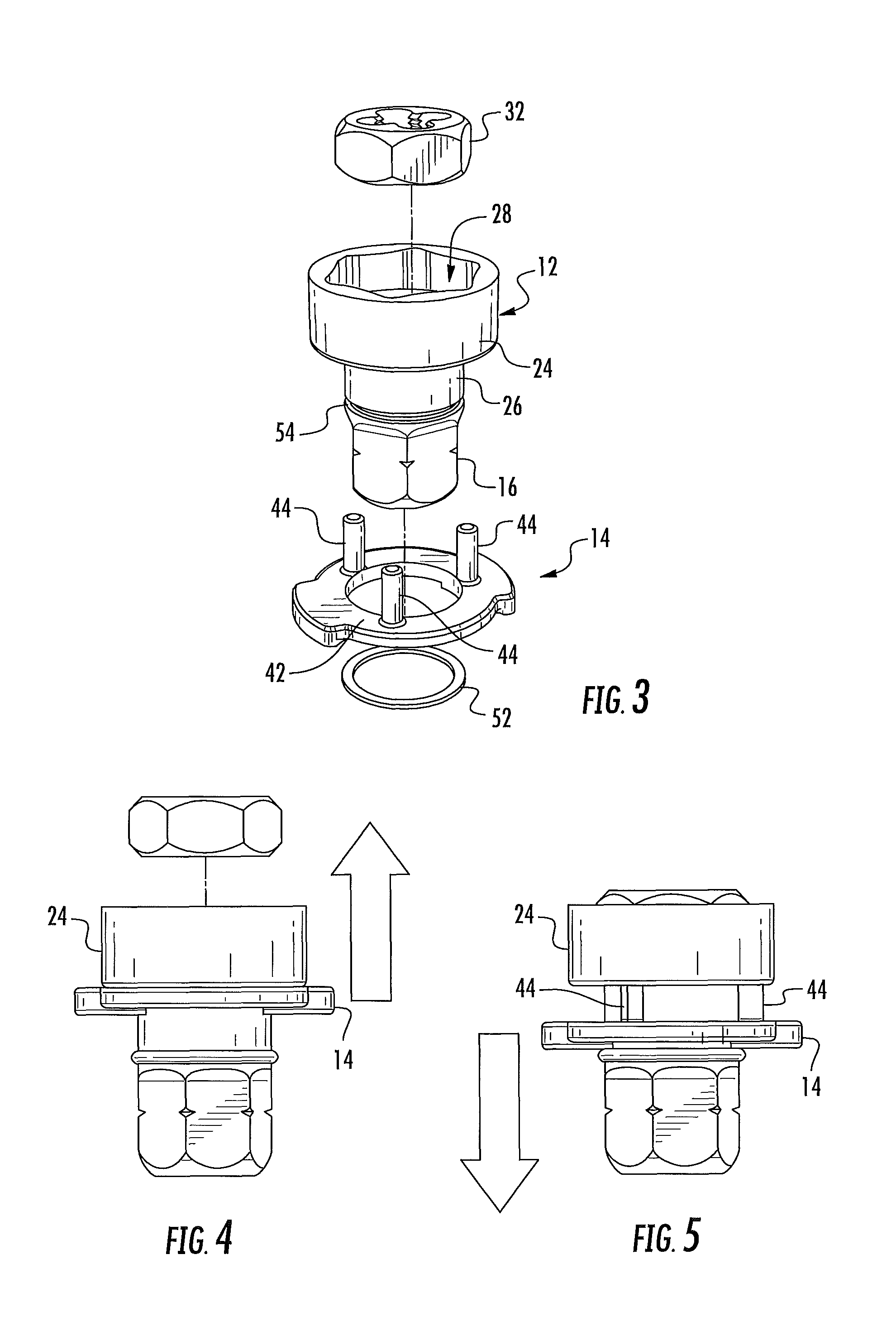
FIG. 3 is an exploded view of the adaptor of FIG. 1.
FIG. 4 illustrates the adaptor with the plunge component raised to eject the thread die.
FIG. 5 illustrates the adaptor with the plunge component lowered to receive the thread die.
FIG. 6 illustrates the adaptor with the plunge component raised to eject the thread die.
FIG. 7 illustrates the adaptor with the plunge component lowered to receive the thread die.
DETAILED DESCRIPTION OF THE DRAWINGS
FIG. 1 shows an exemplary thread die retaining socket 10 according to the present invention. The thread die retaining socket 10 includes an adaptor body 12, a plunge component 14, and means 15 to retain the thread die in the adaptor 10. The plunge component 14 cooperates with the means 15 to selectively retain a thread die in the socket 10.
The adaptor body 12 includes a handle engaging portion 16 configured to engage an aperture 18 formed in a handle 22, illustrated in FIG. 2. The adaptor body 12 further includes a retaining socket 24 and a shaft 26 extending between the handle engaging portion 16 and the retaining socket 24. A central bore 30 extends longitudinally through the adaptor body 12. The socket 24 includes a central cavity 28 for receiving a thread die 32, as illustrated in FIGS. 2-4. The central cavity 28 extends outwardly from the central bore 30, cooperating therewith to form a shoulder 34. The shoulder includes a plurality of apertures 36.
The plunge component 14 includes an annular disc 42 having a plurality of pins 44 extending vertically therefrom and a pair of diametrically opposed arms 46 extending radially outwardly from the disc 42. The pins 44 are located to be operatively disposed in the apertures 36 in the cavity 28. The disc 42 defines a central aperture 48 configured to slideably engage the shaft 26 of the adaptor body 12. The plunge component 14 is configured to move along the shaft 26 between a thread die retaining position, illustrated in FIG. 7, and a thread die ejecting position, illustrated in FIG. 6. An o-ring 52 engages a groove 54 formed in the shaft 26 to retain the plunge component 14 on the shaft 26.
As illustrated in FIGS. 4 and 6, the plunge component 14 can be pushed upwardly, thereby pushing the pins 44 against a thread die 32 in the cavity 28 to at least partially eject the thread die 32 from the socket 24. Pushing the plunge component 14 upwardly lifts the thread die 32 at least partially out of the cavity 28 to a position where it can be grasped and removed from the cavity 28. When the plunge component 14 is pushed down away from the socket 24, as illustrated in FIGS. 5 and 7, the pins 44 are retracted, allowing a thread die 32 to be positioned in the cavity 28.
In one exemplary embodiment, the means 15 for retaining the thread die in the adaptor 10 includes a magnetic washer 62 disposed adjacent the shoulder 34 of the cavity 28. The washer 62 can be retained in the cavity 28 by any conventional method. In another embodiment, the means 15 can include a spring-and-ball detent mechanism. In yet another embodiment, the means 15 can include a magnet disposed in a sidewall of the socket 24. It will be readily apparent to one of ordinary skill in the art that still other methods of retaining the thread die 32 in the cavity 28 are available.
* * * * *
D00000
D00001
D00002
D00003
XML
uspto.report is an independent third-party trademark research tool that is not affiliated, endorsed, or sponsored by the United States Patent and Trademark Office (USPTO) or any other governmental organization. The information provided by uspto.report is based on publicly available data at the time of writing and is intended for informational purposes only.
While we strive to provide accurate and up-to-date information, we do not guarantee the accuracy, completeness, reliability, or suitability of the information displayed on this site. The use of this site is at your own risk. Any reliance you place on such information is therefore strictly at your own risk.
All official trademark data, including owner information, should be verified by visiting the official USPTO website at www.uspto.gov. This site is not intended to replace professional legal advice and should not be used as a substitute for consulting with a legal professional who is knowledgeable about trademark law.