Controller having visually trackable object for interfacing with a gaming system
Mikhailov , et al.
U.S. patent number 10,279,254 [Application Number 12/259,181] was granted by the patent office on 2019-05-07 for controller having visually trackable object for interfacing with a gaming system. This patent grant is currently assigned to Sony Interactive Entertainment Inc.. The grantee listed for this patent is Richard Marks, Anton Mikhailov. Invention is credited to Richard Marks, Anton Mikhailov.


View All Diagrams
| United States Patent | 10,279,254 |
| Mikhailov , et al. | May 7, 2019 |
Controller having visually trackable object for interfacing with a gaming system
Abstract
Methods, systems and computer programs for determining the location in a field of play of a game controller are provided. A ball section is attached to the game controller to locate the controller using visual information. The method obtains an image of the field of play where the game controller is present, and then finds pixels in the image associated with the ball section. The method further establishes an area encompassing the found pixels and determines a geometric shape based on the area associated with the ball. The location of the controller is calculated based on the geometric shape, with the center of the geometric shape indicating the horizontal and vertical location of the controller, and the size of the geometric shape determining the depth of the controller within the field of play. The location is stored in memory, which is used to drive an action by the computer.
| Inventors: | Mikhailov; Anton (Campbell, CA), Marks; Richard (Pleasanton, CA) | ||||||||||
|---|---|---|---|---|---|---|---|---|---|---|---|
| Applicant: |
|
||||||||||
| Assignee: | Sony Interactive Entertainment
Inc. (Tokyo, JP) |
||||||||||
| Family ID: | 41139137 | ||||||||||
| Appl. No.: | 12/259,181 | ||||||||||
| Filed: | October 27, 2008 |
Prior Publication Data
| Document Identifier | Publication Date | |
|---|---|---|
| US 20100105475 A1 | Apr 29, 2010 | |
| US 20120289334 A9 | Nov 15, 2012 | |
Related U.S. Patent Documents
| Application Number | Filing Date | Patent Number | Issue Date | ||
|---|---|---|---|---|---|
| 11588779 | Nov 22, 2011 | 8062126 | |||
| 60730659 | Oct 26, 2005 | ||||
| Current U.S. Class: | 1/1 |
| Current CPC Class: | A63F 13/06 (20130101); A63F 13/24 (20140902); G06F 3/017 (20130101); A63F 13/10 (20130101); A63F 13/42 (20140902); G06F 3/0346 (20130101); G06F 3/0304 (20130101); A63F 13/213 (20140902); A63F 2300/6045 (20130101); A63F 2300/1043 (20130101); A63F 2300/1093 (20130101) |
| Current International Class: | A63F 13/24 (20140101); A63F 13/213 (20140101); A63F 13/20 (20140101); A63F 13/40 (20140101); A63F 13/42 (20140101); G06F 3/01 (20060101); G06F 3/0346 (20130101); G06F 3/03 (20060101) |
| Field of Search: | ;463/30-33,36-39 ;345/169 ;341/20 ;700/91-93 |
References Cited [Referenced By]
U.S. Patent Documents
| 3943277 | March 1976 | Everly et al. |
| 4263504 | April 1981 | Thomas |
| 4313227 | January 1982 | Eder |
| 4558864 | December 1985 | Medwedeff |
| 4565999 | January 1986 | King et al. |
| 4787051 | November 1988 | Olson |
| 4802227 | January 1989 | Elko et al. |
| 4823001 | April 1989 | Kobayashi et al. |
| 4843568 | June 1989 | Krueger et al. |
| 4959810 | September 1990 | Darbee et al. |
| 4963858 | October 1990 | Chien |
| 5034986 | July 1991 | Karmann et al. |
| 5055840 | October 1991 | Bartlett |
| 5111401 | May 1992 | Everett et al. |
| 5128671 | July 1992 | Thomas, Jr. |
| 5144594 | September 1992 | Gilchrist |
| 5260556 | November 1993 | Lake et al. |
| 5297061 | March 1994 | Dementhon et al. |
| 5317140 | May 1994 | Dunthorn |
| 5335011 | August 1994 | Addeo et al. |
| 5394168 | February 1995 | Smith, III et al. |
| 5414426 | May 1995 | O'Donnell et al. |
| 5426450 | June 1995 | Drumm |
| 5453758 | September 1995 | Sato |
| 5455685 | October 1995 | Mori |
| 5473701 | December 1995 | Cezanne et al. |
| 5485273 | January 1996 | Mark et al. |
| 5517333 | May 1996 | Tamura et al. |
| 5528265 | June 1996 | Harrison |
| 5534917 | July 1996 | MacDougall |
| 5543818 | August 1996 | Scott |
| 5557684 | September 1996 | Wang et al. |
| 5563988 | October 1996 | Maes et al. |
| 5568928 | October 1996 | Munson et al. |
| 5581276 | December 1996 | Cipolla et al. |
| 5583478 | December 1996 | Renzi |
| 5586231 | December 1996 | Florent et al. |
| 5611000 | March 1997 | Szeliski et al. |
| 5611731 | March 1997 | Bouton et al. |
| 5616078 | April 1997 | Oh |
| 5638228 | June 1997 | Thomas, III |
| 5649021 | July 1997 | Matey et al. |
| 5675825 | October 1997 | Dreyer et al. |
| 5675828 | October 1997 | Stoel et al. |
| 5677710 | October 1997 | Thompson-Rohrlich |
| 5706364 | January 1998 | Kopec et al. |
| 5768415 | June 1998 | Jagadish et al. |
| 5796354 | August 1998 | Cartabiano et al. |
| 5818424 | October 1998 | Korth |
| 5846086 | December 1998 | Bizzi et al. |
| 5850222 | December 1998 | Cone |
| 5850473 | December 1998 | Andersson |
| 5861910 | January 1999 | McGarry et al. |
| 5870100 | February 1999 | DeFreitas |
| 5883616 | March 1999 | Koizumi et al. |
| 5889505 | March 1999 | Toyama et al. |
| 5889672 | March 1999 | Schuler et al. |
| 5900863 | May 1999 | Numazaki |
| 5913727 | June 1999 | Ahdoot |
| 5914723 | June 1999 | Gajewska |
| 5917493 | June 1999 | Tan et al. |
| 5917936 | June 1999 | Katto |
| 5923306 | July 1999 | Smith et al. |
| 5923318 | July 1999 | Zhai et al. |
| 5929444 | July 1999 | Leichner |
| 5930383 | July 1999 | Netzer |
| 5930741 | July 1999 | Kramer |
| 5937081 | August 1999 | O'Brill et al. |
| 5959596 | September 1999 | McCarten et al. |
| 5963250 | October 1999 | Parker et al. |
| 5993314 | November 1999 | Dannenberg et al. |
| 6009210 | December 1999 | Kang |
| 6014167 | January 2000 | Suito et al. |
| 6021219 | February 2000 | Andersson et al. |
| 6031545 | February 2000 | Ellenby et al. |
| 6031934 | February 2000 | Ahmad et al. |
| 6037942 | March 2000 | Millington |
| 6044181 | March 2000 | Szeliski et al. |
| 6049619 | April 2000 | Anandan et al. |
| 6056640 | May 2000 | Schaaij |
| 6057909 | May 2000 | Yahav et al. |
| 6061055 | May 2000 | Marks |
| 6072494 | June 2000 | Nguyen |
| 6075895 | June 2000 | Qiao et al. |
| 6078789 | June 2000 | Bodenmann et al. |
| 6091905 | July 2000 | Yahav et al. |
| 6094625 | July 2000 | Ralston |
| 6097369 | August 2000 | Wambach |
| 6100517 | August 2000 | Yahav et al. |
| 6100895 | August 2000 | Miura et al. |
| 6101289 | August 2000 | Kellner |
| 6115052 | September 2000 | Freeman et al. |
| 6134346 | October 2000 | Berman et al. |
| 6144367 | November 2000 | Berstis |
| 6151009 | November 2000 | Kanade et al. |
| 6157368 | December 2000 | Faeger |
| 6160540 | December 2000 | Fishkin et al. |
| 6166744 | December 2000 | Jaszlics et al. |
| 6173059 | January 2001 | Huang et al. |
| 6175343 | January 2001 | Mitchell et al. |
| 6184863 | February 2001 | Sibert et al. |
| 6191773 | February 2001 | Maruno et al. |
| 6195104 | February 2001 | Lyons |
| 6215898 | April 2001 | Woodfill et al. |
| 6243074 | June 2001 | Fishkin et al. |
| 6243491 | June 2001 | Andersson |
| 6275213 | August 2001 | Tremblay et al. |
| 6281930 | August 2001 | Parker et al. |
| 6282362 | August 2001 | Murphy |
| 6295064 | September 2001 | Yamaguchi |
| 6297838 | October 2001 | Chang et al. |
| 6304267 | October 2001 | Sata |
| 6307549 | October 2001 | King et al. |
| 6307568 | October 2001 | Rom |
| 6323839 | November 2001 | Fukuda et al. |
| 6323942 | November 2001 | Bamji |
| 6326901 | December 2001 | Gonzales |
| 6327073 | December 2001 | Yahav et al. |
| 6331911 | December 2001 | Manassen et al. |
| 6346929 | February 2002 | Fukushima et al. |
| 6351661 | February 2002 | Cosman |
| 6358145 | March 2002 | Wong et al. |
| 6371849 | April 2002 | Togami |
| 6375572 | April 2002 | Masuyama et al. |
| 6392644 | May 2002 | Miyata et al. |
| 6393142 | May 2002 | Swain et al. |
| 6394897 | May 2002 | Togami |
| 6400374 | June 2002 | Lanier |
| 6409602 | June 2002 | Wiltshire et al. |
| 6411392 | June 2002 | Bender et al. |
| 6411744 | June 2002 | Edwards |
| 6417836 | July 2002 | Kumar et al. |
| 6441825 | August 2002 | Peters |
| 6473516 | October 2002 | Kawaguchi et al. |
| 6498860 | December 2002 | Sasaki et al. |
| 6504535 | January 2003 | Edmark |
| 6513160 | January 2003 | Dureau |
| 6516466 | February 2003 | Jackson |
| 6533420 | March 2003 | Eichenlaub |
| 6542927 | April 2003 | Rhoads |
| 6545706 | April 2003 | Edwards et al. |
| 6546153 | April 2003 | Hoydal |
| 6556704 | April 2003 | Chen |
| 6577748 | June 2003 | Chang |
| 6580414 | June 2003 | Wergen et al. |
| 6580415 | June 2003 | Kato et al. |
| 6587573 | July 2003 | Stam et al. |
| 6593956 | July 2003 | Potts et al. |
| 6595642 | July 2003 | Wirth |
| 6621938 | September 2003 | Tanaka et al. |
| 6628265 | September 2003 | Hwang |
| 6661914 | December 2003 | Dufour |
| 6674415 | January 2004 | Nakamura et al. |
| 6676522 | January 2004 | Rowe et al. |
| 6677967 | January 2004 | Swano et al. |
| 6677987 | January 2004 | Girod |
| 6709108 | March 2004 | Levine et al. |
| 6720949 | April 2004 | Pryor et al. |
| 6727988 | April 2004 | Kim et al. |
| 6741741 | May 2004 | Farrell |
| 6746124 | June 2004 | Fischer et al. |
| 6749510 | June 2004 | Giobbi |
| 6751338 | June 2004 | Wallack |
| 6753849 | June 2004 | Curran et al. |
| 6767282 | July 2004 | Matsuyama et al. |
| 6769769 | August 2004 | Podlleanu et al. |
| 6772057 | August 2004 | Breed et al. |
| 6774939 | August 2004 | Peng |
| 6785329 | August 2004 | Pan et al. |
| 6789967 | September 2004 | Forester |
| 6791531 | September 2004 | Johnston et al. |
| 6795068 | September 2004 | Marks |
| 6809776 | October 2004 | Simpson et al. |
| 6819318 | November 2004 | Geng |
| 6846238 | January 2005 | Wells |
| 6847311 | January 2005 | Li |
| 6863609 | March 2005 | Okuda et al. |
| 6881147 | April 2005 | Naghi et al. |
| 6884171 | April 2005 | Eck et al. |
| 6890262 | May 2005 | Oishi et al. |
| 6917688 | July 2005 | Yu et al. |
| 6919824 | July 2005 | Lee |
| 6924787 | August 2005 | Kramer et al. |
| 6928180 | August 2005 | Stam et al. |
| 6930725 | August 2005 | Hayashi |
| 6931125 | August 2005 | Smallwood |
| 6931596 | August 2005 | Gutta et al. |
| 6943776 | September 2005 | Ehrenburg |
| 6945653 | September 2005 | Kobori et al. |
| 6947576 | September 2005 | Stam et al. |
| 6951515 | October 2005 | Ohshima et al. |
| 6952198 | October 2005 | Hansen |
| 6965362 | November 2005 | Ishizuka |
| 6970183 | November 2005 | Monroe |
| 6990639 | January 2006 | Wilson |
| 7006009 | February 2006 | Newman |
| 7016411 | March 2006 | Azuma et al. |
| 7023475 | April 2006 | Bean et al. |
| 7039199 | May 2006 | Rui |
| 7039253 | May 2006 | Matsuoka et al. |
| 7042440 | May 2006 | Pryor et al. |
| 7043056 | May 2006 | Edwards et al. |
| 7054452 | May 2006 | Ukita |
| 7059962 | June 2006 | Watashiba |
| 7061507 | June 2006 | Tuomi et al. |
| 7071914 | July 2006 | Marks |
| 7084887 | August 2006 | Sato et al. |
| 7090352 | August 2006 | Kobor et al. |
| 7098891 | August 2006 | Pryor |
| 7102615 | September 2006 | Marks |
| 7106366 | September 2006 | Parker et al. |
| 7116330 | October 2006 | Marshall et al. |
| 7116342 | October 2006 | Dengler et al. |
| 7121946 | October 2006 | Paul et al. |
| 7139767 | November 2006 | Taylor et al. |
| 7148922 | December 2006 | Shimada |
| 7158118 | January 2007 | Liberty |
| 7161634 | January 2007 | Long |
| 7164413 | January 2007 | Davis et al. |
| 7183929 | February 2007 | Antebi et al. |
| 7212308 | May 2007 | Morgan |
| 7223173 | May 2007 | Masuyama et al. |
| 7224384 | May 2007 | Iddan et al. |
| 7227526 | June 2007 | Hildreth et al. |
| 7227976 | June 2007 | Jung et al. |
| 7277526 | June 2007 | Hildregh et al. |
| 7239301 | July 2007 | Liberty et al. |
| 7245273 | July 2007 | Eberl et al. |
| 7259375 | August 2007 | Tichit et al. |
| 7262760 | August 2007 | Liberty |
| 7263462 | August 2007 | Funge et al. |
| 7274305 | September 2007 | Luttrell |
| 7283679 | October 2007 | Okada et al. |
| 7296007 | November 2007 | Funge et al. |
| 7301530 | November 2007 | Lee et al. |
| 7305114 | December 2007 | Wolff et al. |
| 7331856 | February 2008 | Nakamura et al. |
| 7346387 | March 2008 | Wachter et al. |
| 7352359 | April 2008 | Zalewski et al. |
| 7364297 | April 2008 | Goldfain et al. |
| 7379559 | May 2008 | Wallace et al. |
| 7391409 | June 2008 | Zalewski et al. |
| 7414611 | August 2008 | Liberty |
| 7436887 | October 2008 | Yeredor et al. |
| 7446650 | November 2008 | Scholfield et al. |
| 7489298 | February 2009 | Liberty |
| 7489299 | February 2009 | Liberty et al. |
| 7545926 | June 2009 | Mao |
| 7558698 | July 2009 | Funge et al. |
| 7613610 | November 2009 | Zimmerman et al. |
| 7623115 | November 2009 | Marks |
| 7627139 | December 2009 | Marks et al. |
| 7636645 | December 2009 | Yen et al. |
| 7636697 | December 2009 | Dobson et al. |
| 7636701 | December 2009 | Funge et al. |
| 7697700 | April 2010 | Mao |
| 7721231 | May 2010 | Wilson |
| 2001/0056477 | December 2001 | McTernan et al. |
| 2002/0010655 | January 2002 | Kjallstrom |
| 2002/0056114 | May 2002 | Fillebrown et al. |
| 2002/0065121 | May 2002 | Fukunaga et al. |
| 2002/0072414 | June 2002 | Stylinski et al. |
| 2002/0075286 | June 2002 | Yonezawa et al. |
| 2002/0083461 | June 2002 | Hutcheson et al. |
| 2002/0085097 | July 2002 | Colmenarez et al. |
| 2002/0094189 | July 2002 | Navab et al. |
| 2002/0103025 | August 2002 | Murzanski et al. |
| 2002/0126899 | September 2002 | Farrell |
| 2002/0134151 | September 2002 | Naruoka et al. |
| 2003/0014212 | January 2003 | Ralston et al. |
| 2003/0022716 | January 2003 | Park et al. |
| 2003/0093591 | May 2003 | Hohl |
| 2003/0100363 | May 2003 | Ali |
| 2003/0123705 | July 2003 | Stam et al. |
| 2003/0160862 | August 2003 | Charlier et al. |
| 2003/0232649 | December 2003 | Gizis et al. |
| 2004/0001082 | January 2004 | Said |
| 2004/0017355 | January 2004 | Shim |
| 2004/0054512 | March 2004 | Kim et al. |
| 2004/0063480 | April 2004 | Wang |
| 2004/0063481 | April 2004 | Wang |
| 2004/0070565 | April 2004 | Nayar et al. |
| 2004/0087366 | May 2004 | Shum et al. |
| 2004/0095327 | May 2004 | Lo |
| 2004/0140955 | July 2004 | Metz |
| 2004/0150728 | August 2004 | Ogino |
| 2004/0165384 | August 2004 | Allen |
| 2004/0178576 | September 2004 | Hillis et al. |
| 2004/0207597 | October 2004 | Marks |
| 2004/0212589 | October 2004 | Hall et al. |
| 2004/0213419 | October 2004 | Varma et al. |
| 2004/0227725 | November 2004 | Calarco et al. |
| 2004/0254017 | December 2004 | Cheng |
| 2004/0256630 | December 2004 | Cao |
| 2005/0009605 | January 2005 | Rosenberg et al. |
| 2005/0037844 | February 2005 | Shum et al. |
| 2005/0047611 | March 2005 | Mao |
| 2005/0088369 | April 2005 | Yoshioka |
| 2005/0102374 | May 2005 | Moragne et al. |
| 2005/0105777 | May 2005 | Koslowski et al. |
| 2005/0117045 | June 2005 | Abdellatif et al. |
| 2005/0130743 | June 2005 | Leifer |
| 2005/0198095 | September 2005 | Du et al. |
| 2005/0226431 | October 2005 | Mao |
| 2005/0239548 | October 2005 | Ueshima et al. |
| 2005/0245316 | November 2005 | Tanaka et al. |
| 2006/0033713 | February 2006 | Pryor |
| 2006/0035710 | February 2006 | Festejo et al. |
| 2006/0038819 | February 2006 | Festejo et al. |
| 2006/0084504 | April 2006 | Chan et al. |
| 2006/0204012 | September 2006 | Marks et al. |
| 2006/0233389 | October 2006 | Mao et al. |
| 2006/0250681 | November 2006 | Zalewski et al. |
| 2006/0252541 | November 2006 | Zalewski et al. |
| 2006/0256081 | November 2006 | Zalewski et al. |
| 2006/0264258 | November 2006 | Zalewski et al. |
| 2006/0264259 | November 2006 | Zalewski et al. |
| 2006/0264260 | November 2006 | Zalewski et al. |
| 2006/0269072 | November 2006 | Mao |
| 2006/0269073 | November 2006 | Mao |
| 2006/0274032 | December 2006 | Mao et al. |
| 2006/0274911 | December 2006 | Mao et al. |
| 2006/0277571 | December 2006 | Marks et al. |
| 2006/0280312 | December 2006 | Mao |
| 2006/0282873 | December 2006 | Zalewski et al. |
| 2006/0287084 | December 2006 | Mao et al. |
| 2006/0287085 | December 2006 | Mao et al. |
| 2006/0287086 | December 2006 | Zalewski et al. |
| 2006/0287087 | December 2006 | Zalewski et al. |
| 2007/0015558 | January 2007 | Zalewski et al. |
| 2007/0015559 | January 2007 | Zalewski et al. |
| 2007/0021208 | January 2007 | Mao et al. |
| 2007/0025562 | February 2007 | Zalewski et al. |
| 2007/0060336 | March 2007 | Marks et al. |
| 2007/0061413 | March 2007 | Larsen et al. |
| 2007/0066394 | March 2007 | Ikeda et al. |
| 2007/0072675 | March 2007 | Hammano et al. |
| 2007/0111796 | May 2007 | Giaimo, III et al |
| 2007/0117625 | May 2007 | Marks et al. |
| 2007/0120834 | May 2007 | Boillot |
| 2007/0120996 | May 2007 | Boillot |
| 2007/0218994 | September 2007 | Goto et al. |
| 2007/0260340 | November 2007 | Mao |
| 2007/0260517 | November 2007 | Zalewski et al. |
| 2007/0261077 | November 2007 | Zalewski et al. |
| 2008/0056561 | March 2008 | Sawachi |
| 2008/0070684 | March 2008 | Haigh-Hutchinson |
| 2008/0091421 | April 2008 | Gustavsson |
| 2008/0111789 | May 2008 | Young et al. |
| 2008/0261693 | October 2008 | Zalewski |
| 2008/0274804 | November 2008 | Harrison et al. |
| 2009/0010494 | January 2009 | Bechtel et al. |
| 2009/0016642 | January 2009 | Hart |
| 2009/0122146 | May 2009 | Zalewski et al. |
| 2009/0209343 | August 2009 | Foxlin et al. |
| 2009/0221368 | September 2009 | Yen et al. |
| 2009/0221374 | September 2009 | Yen et al. |
| 2009/0288064 | November 2009 | Yen et al. |
| 2010/0004896 | January 2010 | Yen et al. |
| 2010/0137064 | June 2010 | Shum et al. |
| 2011/0294579 | December 2011 | Marks et al. |
| 2549527 | May 2003 | CN | |||
| 0353200 | Jan 1990 | EP | |||
| 0652686 | May 1995 | EP | |||
| 0750202 | Dec 1996 | EP | |||
| 0835676 | Apr 1998 | EP | |||
| 1098686 | May 2003 | EP | |||
| 1435258 | Jul 2004 | EP | |||
| 2 135 651 | Dec 2009 | EP | |||
| 2814965 | Apr 2002 | FR | |||
| 2206716 | Nov 1989 | GB | |||
| 2376397 | Nov 2002 | GB | |||
| 2388418 | Nov 2003 | GB | |||
| 1284897 | Nov 1989 | JP | |||
| 6102980 | Apr 1994 | JP | |||
| 9128141 | May 1997 | JP | |||
| 9185456 | Jul 1997 | JP | |||
| 9-265346 | Oct 1997 | JP | |||
| 1138949 | Feb 1999 | JP | |||
| 2000-172431 | Jun 2000 | JP | |||
| 2000172431 | Jun 2000 | JP | |||
| 2000259856 | Sep 2000 | JP | |||
| 2000350859 | Dec 2000 | JP | |||
| 2001-166676 | Jun 2001 | JP | |||
| 2001166676 | Jun 2001 | JP | |||
| 2002369969 | Dec 2002 | JP | |||
| 2004-145448 | May 2004 | JP | |||
| 2004145448 | May 2004 | JP | |||
| 2005046422 | Feb 2005 | JP | |||
| 200525410 | Aug 2005 | TW | |||
| WO 88/05942 | Aug 1988 | WO | |||
| WO 98/48571 | Oct 1998 | WO | |||
| WO 99/35633 | Jul 1999 | WO | |||
| WO 99/26198 | Oct 1999 | WO | |||
| WO 02/27456 | Feb 2002 | WO | |||
| WO 3/079179 | Sep 2003 | WO | |||
| WO 05/073838 | Aug 2005 | WO | |||
| WO 2005107911 | Nov 2005 | WO | |||
| WO 2008/056180 | May 2008 | WO | |||
Other References
|
"The Tracking Cube: A Three-Dimentional Input Device", IBM Technical Disclosure Bulletin, Aug. 1, 1989, pp. 91-95, No. 3B, IBM Corp.New York, U.S. cited by applicant . K. B. Shimoga, et al., "Touch and Force Reflection for Telepresence Surgery", Engineering in Medicine and Biology Opportunities of the IEEEE, Baltimore, MD, USA, Nov. 3, 1994, New York, New York, USA, pp. 1049-1050. cited by applicant . Iddan, et al., "3D Imaging in the Studio (and Elsewhere . . . )", Proceedings of the SPIE, SPIE, Bellingham, VA, US, vol. 4298, Jan. 24, 2001, pp. 48-55, XP008005351. cited by applicant . Jojic, et al., "Tracking Self-Occluding Articulated Objects in Dense Disparity Maps", Computer Vision, 1999, The Proceedings fo the Seventh IEEE International Conference on Kerkyra, Greece Sep. 20-27, 1999, Los Alamitos, CA, US, IEEE Computer Society, US, Sep. 20, 1999, (Sep. 20, 1999), pp. 123-130. cited by applicant . Klinker, et al., "Distributed User Tracking Concepts for Augmented Reality Applications", pp. 37-44, Augmented Reality, 2000, IEEE and ACM Int'l Symposium, Oct. 2000, XP010520308, ISBN: 0-7695-0846-4, Germany. cited by applicant . Nakagawa, et al., "A Collision Detection and Motion Image Synthesis Between a Background Image and a Foreground 3-Dimensional Object", TVRSJ Bol. 4, No. 2, pp. 425-430, 1999, Japan. cited by applicant . Mihara, et al., "A Realtime Vision-Based Interface Using Motion Processor and Applications to Robotics", vol. J84-D-11, No. 9, pp. 2070-2078, Sep. 2001, Japan. cited by applicant . Nakamura, et al., "A Consideration on Reconstructing 3-D Model Using Object Views", 2004-01601-003, pp. 17-21, Kokkaido University, Japan, nakamura@media.eng.hokudai.ac.jp. cited by applicant . Nishida, et al., "A Method of Estimating Human Shapes by Fitting the Standard Human Model to Partial Measured Data", D-II vol. J84-D-II, No. 7, pp. 1310-1318, Jul. 2001. cited by applicant . Wilson & Darrell, "Audio-Video Array Source Localization for Intelligent Environments", 2002 IEEE Dept. of Electrical Eng and Computer Science, MIT, Cambridge, MA 02139. cited by applicant . Fiala, et al., "A Panoramic Video and Acoustic Beamforming Sensor for Videoconferencing", 2004 IEEE, Computational Video Group, National Research Council, Ottawa, Canada K1A 0R6. cited by applicant . Hemmi, et al., "3-D Natural Interactive Interface--Using Marker Tracking from a Single View",Sep. 9, 1991, Systems and Computers in Japan. cited by applicant . Bolt, R.A., "Put-that-there": voice and gesture at the graphics interface,Computer Graphics, vol. 14, No. 3 (ACM SIGGRAPH Conference Proceedings) Jul. 1980, pp. 262-270. cited by applicant . DeWitt, Thomas and Edelstein, Phil "Pantomation: A System for Position Tracking", Proceedings of the 2.sup.nd Symposium on Small Computers in the Arts, Oct. 1982, pp. 61-69. cited by applicant . Kanade, et al., "A Stereo Machine for Video-rate Dense Depth Mapping and Its New Application" 1996, CVPR 96, IEEE Computer Society Conference, pp. 196-202 (022). cited by applicant . Gvili, et al., "Depth Keying", SPIE vol. 5006 (2003), 2003 SPIE-IS&T, pp. 564-574 (031). cited by applicant . Ephraim et al. "Speech Enhancement Using a Minimum Mean-Square Error Log--Spectral Amplitude Estimator", 1985, IEEE. cited by applicant . Ephraim et al. "Speech Enhancement Using a Minimum Mean-Square Error Short--Time Spectral Amplitude Estimator", 1984, IEEE. cited by applicant . Richardson et al. "Virtual Network Computing", 1998, IEEE Internet Computing vol. 2. cited by applicant . XP-002453974, "CFS and FS95/98/2000: How to Use the Trim Controls to Keep Your Aircraft Level", Aug. 10, 2007, http://support.microsoft.com/?scid=kb%3Ben-us%3B175195&x=13&y=15. cited by applicant . Richardson et al., "Virtual Network Computing" IEEE Internet Computing, vol. 2,No. 1 Jan./Feb. 1998. cited by applicant . Fujitsu, "Internet Development of Emulators" Abstract, Mar. 1997, vol. 48, No. 2. cited by applicant . Lanier, Jaron, "Virtually there: three-dimensional tele-immersion may eventually bring the world to your desk", Scientific American, ISSN: 0036-8733, Year: 2001. cited by applicant . Taiwan Intellectual Property Office, "Taiwan IPO Search Report (with English translation)" for Taiwan Invention Patent Application No. 098129110, completed Jan. 2, 2013. cited by applicant . Chinese Office Action, App. No. 2010800647079, PVD83056A, Oct. 24, 2014. cited by applicant . Lakshminarayanan_"Practical device association protocols for wireless enabled personal devices", pp. 2484-2489, Inst. for Infocomm Research, Singapore, IEEE Comm. Soc. WCNC Feb. 2005. cited by applicant. |
Primary Examiner: Skaarup; Jason
Attorney, Agent or Firm: Penilla IP, APC
Parent Case Text
CLAIM OF PRIORITY
This application claims priority under 35 USC .sctn. 120 as a continuation-in-part of U.S. Pat. No. 8,062,126, with application Ser. No. 11/588,779, filed on Oct. 26, 2006, entitled "System and Method for Interfacing with a Computer Program," which claims priority to U.S. Provisional Patent Application No. 60/730,659, filed Oct. 26, 2005, entitled "System and Method for Interfacing with a Computer Program.
CROSS REFERENCE TO RELATED APPLICATIONS
This application is related to U.S. patent application Ser. No. 12/145,455, filed Jun. 24, 2008, and entitled "DETERMINATION OF CONTROLLER THREE-DIMENSIONAL LOCATION USING IMAGE ANALYSIS AND ULTRASONIC COMMUNICATION", which is incorporated herein by reference.
Claims
What is claimed is:
1. A video game controller for wireless interfacing with a computing system, the video game controller comprising: an elongated body in a form of a handle, the elongated body having a first end and a second end; an object disposed at the second end of the elongated body, the second end being opposite to the first end along a longest dimension of the elongated body, the object having a shape for visual recognition; a light source exposed in the object, wherein the object is defined to be illuminated when the light source is active; buttons disposed between the first end and the second end of the elongated body; an inertial sensor disposed within the elongated body; and one or more circuits disposed in the elongated body, the one or more circuits defined to be in communication with the light source, the buttons, the inertial sensor, and an antenna, the antenna provided for wireless communication to and from the computing system.
2. The video game controller as recited in claim 1, wherein the shape of the object is selected from a group consisting of a spherical section, a partial sphere, an imperfect sphere, an elongated ball, or a cube.
3. The video game controller as recited in claim 1, wherein the object is translucent.
4. The video game controller as recited in claim 1, wherein the object is plastic.
5. The video game controller as recited in claim 1, wherein the light source is a light-emitting diode (LED).
6. The video game controller as recited in claim 1, wherein the light source provides one or more of a plurality of colors or a white light.
7. The video game controller as recited in claim 1, wherein the one or more circuits are operable to set the light source as active or as inactive.
8. The video game controller as recited in claim 1, wherein one of the buttons is a trigger button defined to be operable by an index finger of a hand holding the controller by the handle.
9. The video game controller as recited in claim 1, wherein the handle further includes a universal serial bus (USB) port in communication with the one or more circuits.
10. The video game controller as recited in claim 1, wherein the wireless communication includes at least one or more of Bluetooth, wireless network (WiFi), or ultrasound.
11. The video game controller as recited in claim 1, wherein the one or more circuits include a processor.
12. The video game controller as recited in claim 1, wherein the one or more circuits include a memory.
13. The video game controller as recited in claim 1, wherein the inertial sensor is defined by one or more of an accelerometer, a magnetometer, or a gyroscope in communication with the one or more circuits.
14. A video game controller for wireless interfacing with a computing system, the video game controller comprising: an elongated body in a form of a handle, the elongated body having a first end and a second end; an object disposed at the second end of the elongated body, the second end being opposite to the first end along a longest dimension of the elongated body, the object being defined from a translucent material; a light source exposed in the object; buttons disposed between the first end and the second end of the elongated body; an inertial sensor disposed within the elongated body; and one or more circuits disposed in the elongated body, the one or more circuits defined to be in communication with the light source, the inertial sensor, the buttons, and an antenna, the antenna provided for wireless communication.
15. The video game controller as recited in claim 14, wherein a shape of the object is defined for visual recognition and is selected from a group consisting of a spherical section, a partial sphere, an imperfect sphere, an elongated ball, or a cube.
16. The video game controller as recited in claim 14, wherein the object is defined to be illuminated when the light source is active.
17. The video game controller as recited in claim 14, wherein the light source is a light-emitting diode (LED).
18. The video game controller as recited in claim 14, wherein the light source provides one or more of a plurality of colors or a white light.
19. The video game controller as recited in claim 14, wherein the one or more circuits are operable to set the light source as active or inactive.
20. The video game controller as recited in claim 14, wherein one of the buttons is a trigger button defined to be operable by an index finger.
21. The video game controller as recited in claim 14, wherein the handle further includes a universal serial bus (USB) port in communication with the one or more circuits.
22. The video game controller as recited in claim 14, wherein the one or more circuits include a processor.
23. The video game controller as recited in claim 14, wherein the one or more circuits include a memory.
24. A video game controller for wireless interfacing with a computing system, the video game controller comprising: an elongated body in a form of a handle, the elongated body having a first end and a second end; an object disposed at the second end of the elongated body, the second end being opposite to the first end along a longest dimension of the elongated body, the object having a shape; a light source exposed in the object, wherein the object is defined to be illuminated when the light source is active; buttons disposed between the first end and the second end of the elongated body, wherein one of the buttons is a trigger button defined to be operable by an index finger; a universal serial bus (USB) port on the second end; a battery disposed within the elongated body; and one or more circuits disposed in the elongated body, the one or more circuits defined to be in communication with the light source, the buttons, the USB port, the battery, and an antenna, the antenna provided for wireless communication.
25. The video game controller as recited in claim 24, wherein the shape of the object is selected from a group consisting of a spherical section, a partial sphere, an imperfect sphere, an elongated ball, or a cube.
26. The video game controller as recited in claim 25, wherein the wireless communication includes at least one or more of Bluetooth, wireless network (WiFi), or ultrasound.
27. The video game controller as recited in claim 24, wherein the object is defined from translucent plastic.
28. The video game controller as recited in claim 24, wherein the light source is a light-emitting diode (LED).
29. The video game controller as recited in claim 24, wherein the light source provides one or more of a plurality of colors or a white light.
30. The video game controller as recited in claim 24, wherein the one or more circuits are operable to set the light source as active or as inactive.
31. The video game controller as recited in claim 24, wherein the one or more circuits include a processor.
32. The video game controller as recited in claim 24, wherein the one or more circuits include a memory.
33. The video game controller as recited in claim 24, wherein the video game controller further includes an inertial sensor inside the handle.
34. A video game controller for wireless interfacing with a computing system, the video game controller comprising: an elongated body in a form of a handle, the elongated body having a first end and a second end; an object disposed at the second end of the elongated body, the second end being opposite to the first end along a longest dimension of the elongated body, the object having a shape of an imperfect sphere; a light source exposed in the object, wherein the object is defined to be illuminated when the light source is active; buttons disposed between the first end and the second end of the elongated body, wherein one of the buttons is a trigger button defined to be operable by an index finger of a hand holding the controller by the handle; an inertial sensor disposed within the elongated body; a battery disposed within the elongated body; and one or more circuits disposed in the elongated body, the one or more circuits defined to be in communication with the light source, the buttons, the inertial sensor, the battery, and an antenna, the antenna provided for wireless communication to and from the computing system.
35. The video game controller as recited in claim 34, wherein the light source is a light-emitting diode (LED).
36. The video game controller as recited in claim 34, wherein the light source provides one or more of a plurality of colors or a white light.
37. The video game controller as recited in claim 34, wherein the handle further includes a universal serial bus (USB) port in communication with the one or more circuits.
38. A video game controller for wireless interfacing with a computing system, the video game controller comprising: an elongated body in a form of a handle, the elongated body having a first end and a second end; an object disposed at the second end of the elongated body, the second end being opposite to the first end along a longest dimension of the elongated body, the object being translucent, plastic, and having a shape for visual recognition; a light source exposed in the object, wherein the object is defined to be illuminated when the light source is active, wherein the light source is a light-emitting diode (LED), wherein the light source provides one or more of a plurality of colors or a white light; buttons disposed between the first end and the second end of the elongated body; an inertial sensor disposed within the elongated body; and one or more circuits disposed in the elongated body, the one or more circuits defined to be in communication with the light source, the buttons, the inertial sensor, and an antenna, the antenna provided for wireless communication to and from the computing system.
Description
BACKGROUND
1. Field of the Invention
The present invention relates generally to tracking the location of a game controller in a field of play, and more specifically to tracking the location and the movement of a game controller, which includes a ball attachment, using visual information.
2. Description of the Related Art
The video game industry has seen many changes over the years. As computing power has expanded, developers of video games have likewise created game software that takes advantage of these increases in computing power. To this end, video game developers have been coding games that incorporate sophisticated operations and mathematics to produce a very realistic game experience.
Example gaming platforms, may be the Sony Playstation.RTM., Sony Playstation2.RTM. (PS2), and Sony Playstation3.RTM. (PS3), each of which is sold in the form of a game console. As is well known, the game console is designed to connect to a monitor (usually a television) and enable user interaction through handheld controllers. The game console is designed with specialized processing hardware, including a CPU, a graphics synthesizer for processing intensive graphics operations, a vector unit for performing geometry transformations, and other glue hardware, firmware, and software. The game console is further designed with an optical disc tray for receiving game compact discs for local play through the game console. Online gaming is also possible, where a user can interactively play against or with other users over the Internet.
As game complexity continues to intrigue players, game and hardware manufacturers have continued to innovate to enable additional interactivity and computer programs. A growing trend in the computer gaming industry is to develop games that increase the interaction between user and the gaming system. One way of accomplishing a richer interactive experience is to use wireless game controllers whose movement is tracked by the gaming system in order to track the player's movements and use these movements as inputs for the game. Generally speaking, gesture input refers to having an electronic device such as a computing system, video game console, smart appliance, etc., react to some gesture captured by a video camera that tracks an object.
However, current object tracking suffers in capture accuracy. This problem arises because conventional image analysis can only produce somewhat reliable measurements of the location of the user in two dimensions, as slight variations in the perceived shape of the controller makes determining the horizontal and vertical position of the controller unreliable and very susceptible to noise. In addition, determining the distance between the camera and the object being tracked is difficult, as the slight changes in shape due to movement towards or away from the camera do not provide enough information to reliably calculate distances between the camera and the controller.
It is within this context that embodiments of the invention arise.
SUMMARY
Embodiments of the present invention provide methods, systems and computer programs for determining the location in a field of play of a game controller. A ball section attached to the game controller aids in locating the controller using visual information.
It should be appreciated that the present invention can be implemented in numerous ways, such as a process, an apparatus, a system, a device or a method on a computer readable medium. Several inventive embodiments of the present invention are described below.
In one embodiment, a computer implements a method to determine a location in a field of play of the game controller. The method obtains an image of the field of play where the game controller is present, and then finds pixels in the image associated with the ball section. The method further establishes an area encompassing the found pixels and determines a geometric shape based on the area associated with the ball. The location of the controller is calculated based on the geometric shape, with the center of the geometric shape indicating the horizontal and vertical location of the controller, and the size of the geometric shape determining the depth of the controller within the field of play. The location is stored in memory, which is used to drive an action by the computer.
In another embodiment, a method is presented to determine the location in a field of play of a game controller. The method obtains an image of the field of play and finds pixels in the image associated with a ring in the ball section connected to the game controller. Further, the method establishes an area that encompasses the pixels found associated with the ring. An ellipse is determined based on the area previously established, and the location of the controller is calculated based on the ellipse, where the center of the ellipse indicates the horizontal and vertical coordinates of the controller, and the size of the ellipse determines the depth of the controller within the field of play. The location is stored in memory, which is used to drive an action by the computer.
In another embodiment, a method is presented to determine a location in a field of play of a game controller using a combination of information sources with respect to the location and movement of the controller. The method obtains an image of the controller and receives status information from the game controller. The status information can be originated in an accelerometer, a gyroscope or a magnetometer. The method determines a geometric shape associated with the ball section connected to the game controller, and calculates the location of the controller by combining the status information with information about the geometric shape.
Other aspects of the invention will become apparent from the following detailed description, taken in conjunction with the accompanying drawings, illustrating by way of example the principles of the invention.
BRIEF DESCRIPTION OF THE DRAWINGS
The invention may best be understood by reference to the following description taken in conjunction with the accompanying drawings in which:
FIGS. 1A-B show embodiments of a game controller with a ball section attached.
FIGS. 1C-E depict different operational modes for the game controller of FIGS. 1A-B.
FIGS. 2A-2B shows other embodiments of a game controller with a ball attached.
FIGS. 3A-3B depict different embodiments of a ball-attached game controller.
FIGS. 4A-D show an embodiment of a ball-attached game controller with interchangeable face-plates.
FIG. 5 shows a schematic diagram of a multiplayer environment and the use of visual information to determine the locations of the different controllers held by the players, according to one embodiment.
FIGS. 6A-6D illustrate different embodiments for assigning a geometric shape to a perceived shape from a captured image.
FIG. 7 illustrates how to use subpixel analysis to find pixels corresponding to the ball section in accordance with one embodiment.
FIG. 8 shows the effects of blurring an image to improve shape detection according to one embodiment of the invention.
FIG. 9 depicts the use of several consecutive captured images to determine ball location according to one embodiment.
FIG. 10 illustrates one embodiment for taking an image from a reduced area of the playing field to increase accuracy.
FIG. 11 depicts image recognition of a ball with a small number of pixels, according to one embodiment.
FIG. 12 depicts one embodiment for image recognition using a high resolution camera.
FIGS. 13A-C illustrate ball detection using an illuminated ring movable to face the camera in accordance with one embodiment.
FIGS. 14A-H illustrate detection of a distinguishable ring in the ball section, according to one embodiment.
FIGS. 15A-B depict a method to estimate a complete ring area from a partial arc section.
FIG. 16 shows and embodiment where the ball vibrates to increase the perceived ball surface.
FIGS. 17A-B depict embodiments of a ball that can change size or appearance to improve detection.
FIG. 18 shows an embodiment of a game controller with a ball section enclosed in a shell.
FIGS. 19A-B describe a controller with sensors for improving movement tracking, according to one embodiment.
FIG. 20 depicts using different sources of information to assess controller position in accordance with one embodiment.
FIGS. 21A-C describe the use of a wheel in a controller to initiate computer actions, according to one embodiment.
FIG. 22 illustrates hardware and user interfaces that may be used to determine controller location, in accordance with one embodiment of the present invention.
FIG. 23 illustrates additional hardware that may be used to process instructions, in accordance with one embodiment of the present invention.
FIG. 24 shows a flow chart describing an embodiment for a method to determine a location in a field of play of a ball-attached game controller.
FIG. 25 includes a flow chart for a method to determine a location in a field of play of a ball with a distinguishable ring, according to one embodiment.
DETAILED DESCRIPTION
The following embodiments describe methods, systems and computer programs for determining the location in a field of play of a game controller. A ball section is attached to the game controller to locate the controller using visual information. The method obtains an image of the field of play where the game controller is present, and then finds pixels in the image associated with the ball section. The method further establishes an area encompassing the found pixels and determines a geometric shape based on the area associated with the ball. The location of the controller is calculated based on the geometric shape, with the center of the geometric shape indicating the horizontal and vertical location of the controller, and the size of the geometric shape determining the depth of the controller within the field of play. The location is stored in memory, which is used to drive an action by the computer.
It will be obvious, however, to one skilled in the art, that the present invention may be practiced without some or all of these specific details. In other instances, well known process operations have not been described in detail in order not to unnecessarily obscure the present invention.
FIGS. 1A-B show embodiments of a game controller with a ball section attached. The ball attached to the controllers can be of different colors, and in one embodiment, the ball can light up. The color in the ball can be driven by RGB (Red Green Blue) Light-Emitting Diodes (LEDs) inside the ball. Additionally, the brightness of the illuminated ball can be controlled in order to track the ball under different camera exposure settings. In one embodiment, the color of the ball is used to differentiate controllers from different users and among controllers held by the same user on different hands.
Although a spherical ball is shown in the controllers of FIGS. 1A and 1B, the ball can have other shapes for visual tracking purposes, such as a partial sphere, an imperfect sphere, an elongated ball (like one used in American football or in rugby), a cube-like shape, etc.
The controllers of FIGS. 1A and 1B are designed for one-hand use, but ball-attached two-hand controllers can also be tracked using embodiments described herein. In one embodiment, the two controllers held by the user on different hands are identical, and in another embodiment the controllers are different. Typically, the controllers will be very similar, being different just in the buttons at each controller. In one embodiment, the controller includes a Universal Serial Bus (USB) connection for charging the controller, Bluetooth for wireless communication with the console, and buttons such as start, select and PS.
In one embodiment, the ball or sphere is 4 cm. in diameter, but other sizes are also possible. Bigger sizes help with visual recognition. A ball with a 5 cm. diameter provides about 55 percent more pixels for image recognition than a 4 cm. ball.
FIGS. 1C-E depict different operational modes for the game controller of FIGS. 1A-B. FIG. 1C shows a "reverse wand" operation, where the ball section is located at the bottom of the controller, and the top includes input buttons. In this configuration, the controller can be used as an arcade flight stick by pivoting on the sphere. In one embodiment, an inertial unit provides the angle of the "stick" (controller) and the twist, and the top surface includes a directional pad. In another embodiment, the top surface holds removable plates to change button configuration, as described below with respect to FIGS. 4A-4D. This mode of operation can be used in firing, driving, flying games, etc.
In one embodiment, the controller includes buttons for the index and middle finger in the reverse wand configuration. As a result, two reverse wand controllers provide the same functionality as a Sony DualShock.RTM.2 controller from Sony Computer Entertainment America Inc.
FIG. 1D shows a controller behind held in a "pencil" configuration. The ball faces the camera for visual identification, and buttons in the body of the controller enable user input. This mode can be use in games where the controller is a paint brush, a flashlight, a pointer, a firing weapon, etc. FIG. 1E illustrate the use of a controller in wand mode. In one embodiment, the wand includes two thumb buttons at the top of the handle and a trigger for the index finger, but other configurations are also possible. The wand mode can be used as a magic-wand, a music director's baton, a tennis racket, a hatchet or similar weapon, a tool such as a pick, an umbrella, a rope, etc.
FIGS. 2A-2B shows other embodiments of a game controller with a ball attached. The body of controllers in FIGS. 2A and 2B are spherical like the attached balls. The controllers have different button configurations and are intended for use in different hands. In one embodiment, the controllers are identical, and can be used either with the left or the right hand. The controllers of FIGS. 2A and 2B are held in a "baseball" configuration, that is, the controller is about the size of a baseball or a tennis ball and is held as a baseball in the palm of the hand. Similar to the configurations in FIGS. 1C to 1E, the controllers in 2A and 2B can be held with the ball attachment pointing in different directions, such as towards the camera, the floor, or the ceiling.
FIGS. 3A-3B depict different embodiments of a ball-attached game controller. The controllers are slimmer and designed for light weight applications.
FIGS. 4A-D show an embodiment of a ball-attached game controller with interchangeable face-plates. FIG. 4A shows a controller, similar to the controllers in FIGS. 1A-B, but with interchangeable face-plates. The face-plates for FIGS. 4B-4D can be attached to the controller, either at the top or at the side. In another embodiment, the sizes of the face plates are different for the slots on the top and the side, and the face plates for the top are not exchangeable with the face plates for the side. FIGS. 4B-4D show a D-pad attachment, an action-buttons pad, and a touch pad, respectively. The attachments include electrical connections and a mechanical grip that snaps the attachments securely when placed on the controller.
FIG. 5 shows a schematic diagram of a multiplayer environment and the use of visual information to determine the locations of the different controllers held by the players, according to one embodiment. Image capture device 508 obtains an image of playing field 518 and the image is analyzed to obtain the location of ball-attached controllers C.sub.1, C.sub.2, C.sub.4 and C.sub.5. Distances d.sub.z1, d.sub.z2, d.sub.z4, and d.sub.z5 are estimated by analyzing the shape of the respective balls in the captured image. Computing system 502, uses the obtained coordinates and distances to produce representations of the players in screen 504, avatars 512a and 512b respectively. A typical distance for good image recognition is about 10 ft (3 mtr). One advantage of using visual recognition is that improvements in image capture and image recognition can be included in the system without having to change the controller.
FIGS. 6A-6D illustrate different embodiments for assigning a geometric shape to a perceived shape from a captured image. FIG. 4A shows some of the problems with determining where the "true" geometric shape (i.e. the ball) given a captured image. Since the ball is a sphere, the goal is to determine the circle that corresponds to the ball in the image captured by the camera. There are different ways of assigning a circle to a perceived shape, such as the one in FIG. 6A, depending on the methodology. For example, a circle inside the received shape could be selected in order to assure that all pixels in the circle are pixels corresponding to the ball, or a circle could be selected that would contain all the shape pixels and the minimum amount of non-shape pixels. Alternatively, the algorithm may focus on detecting the outside curves delimiting the captured shape and then fit a circle that approximates those curves.
In many cases, the number of pixels captured associated with the ball is small. In one embodiment, a ball located at 10 ft. (3 mt.) generates an image where the radius of the circle is 4 pixels. In other words, each pixel corresponds to a depth of 2.5 ft. If a pixel is missed because of noise or because of an inaccurate algorithm, then the location of the player jumps 2.5 ft. As a result, pixel counting by itself does not provide an accurate measure of depth. Additionally, if the ball gets occluded due to the movement of the controller, only a partial image may be captured by the camera. Curve fitting becomes critical to analyze the perceived shape and determine the best location and shape of the ball.
FIG. 6B illustrates estimating the center and the radius r of the circle. The depth, also known herein as z, is related to the area of the ball, and is proportional to 1/r. In one embodiment, the method finds the pixels that correspond to the visual identification of the ball. The pixels associated with the ball are counted to determine the area, and then the center and the r are calculated based on the size.
In another embodiment, the periphery of the shape in FIG. 6B is analyzed to determine the curve surrounding the shape. The curve is analyzed in order to determine the circle that best fits the curve. In one embodiment, the circle chosen is the circle that would have the smallest sum of the unique areas delimited by the circle and the curve surrounding the perceived shape.
FIG. 6C illustrates the difficulty in finding an associated circle given an imperfect shape. Visually inspecting the shape, it can be inferred that only a partial section of the ball has been captured. Doing a straight pixel count to determine the area would not produce an accurate result. In one embodiment, the method checks for the "fuzzy" boundaries around the edges, which may be caused by shadows, light variations, etc., and determines the shape of the outside curve. The perimeter curve of the shape is analyzed to determine the center, also referred to herein as "centroid", and to determine the radius that best fits the area and the outside curve.
FIG. 6D illustrates the "fit the longest stick" method. As previously described, the image is analyzed and a shape of the captured ball is determined. The method determines the longest straight segment, or "stick," that fits inside the shape. The longest segment is then considered the diameter of the circle associated with the ball.
FIG. 7 illustrates how to use subpixel analysis to find pixels corresponding to the ball section in accordance with one embodiment. In many display and image-acquisition systems are, the pixel grid is divided into single-color regions that contribute to the displayed or sensed color when viewed at a distance. In some displays, such as LCD, LED, and plasma displays, these single-color regions are separately addressable elements, which have come to be known as subpixels. For example, LCDs typically divide each pixel 702 into three subpixels 704, 706, and 708.
In one embodiment, the pixel analysis focuses on just one color, such as blue. In other embodiments, the analysis focuses on the combination of two subpixels, improving accuracy but requiring more computation. Additionally, the analysis of one pixel is not constrained to analyzing the pixel, or the subpixels in the pixel, and nearby pixels are analyzed to improve accuracy and reduce the effects of noise or other conditions such as inconsistent lighting.
FIG. 8 shows the effects of blurring an image to improve shape detection according to one embodiment of the invention. The image is taking with the camera slightly out of focus causing a blurring effect on the ball, which causes the perceived area of the ball to be bigger than an image taken without blurring. A larger area means more pixels for analysis and improved accuracy.
FIG. 9 depicts the use of several consecutive captured images to determine ball location according to one embodiment, referred to herein as smoothing. In one embodiment, the captured images are not analyzed in isolation. The information from one image is compared with previously taken images. If the image-taking frequency is high enough, consecutive images will be similar, even after factoring the movement of the controller. As a result, the information from previous images can be used to detect sudden anomalous pixel variations, which are likely caused by noise, bad lighting, ball occlusion, etc.
In one embodiment, the information from previous images is weighted in inverse proportion to their age, that is, older images are given smaller weights, as the information that they convey becomes less relevant.
FIG. 10 illustrates one embodiment for taking an image from a reduced area 156 of the playing field 152 to increase accuracy. The computer system keeps track of the movement of the ball, together with the controller attached to the ball, and has the expectation that the ball will be in about the same place as the last time an image was taken, assuming the video taking frequency is adequate to allow for small movements of the controller between images. In one embodiment, the video taking camera as zoom capabilities and takes image 154 of reduced area 156 where the ball was in the last image and a buffer area around the ball to allow for movement of the controller. The image of the reduced area has higher resolution and provides more pixels associated with the ball for better location determination.
As a result, the field of play where the ball is present is reduced when taking the image of the reduced area, but this can be easily compensated by tracking the movement of the ball in order to capture zoomed-in images centered around the last known position of the ball.
In another embodiment, the camera is able to zoom-in only in the center of the field of play. In this case, the zoom-in function is only used when the ball is located towards the center of the field of play. This will cause the resolution to be better when the player is located around the center of the field of play and worse when the ball is located in the periphery of the field of play.
FIG. 11 depicts image recognition of a ball with a small number of pixels, according to one embodiment. As previously described with respect to FIG. 6A, recognition of a ball when few pixels are available can cause big changes in the perceived shape when even one pixel is missed or miscalculated. The problem of few-pixel availability can be aggravated when the ball moves across pixel boundaries. In a first position 160 of the ball, the method perceives the ball as having four pixels. In one embodiment, the method determines that a pixel is associated with the color of the ball when at least fifty percent of the pixel corresponds to the ball, but other embodiments may use other percentages as the threshold. As the ball moves to second position 162, the method perceives 7 pixels associated with the ball. Because the ball corresponds to a few pixels, the position of the ball in the pixel grid is a factor under the scenario in FIG. 11. In addition, the problem can be compounded with other factors such as noise and rasterization.
One embodiment solves the small number of pixels problem by using a higher resolution camera. FIG. 12 depicts one embodiment for image recognition using a high resolution camera. Because the ball includes a larger number of pixels, small movements of the ball across the pixel grid will have a smaller impact on shape recognition than when using a lower resolution camera.
FIGS. 13A-C illustrate ball detection using an illuminated ring movable to face the camera in accordance with one embodiment. Controller 170 has a ball section 172 attached for visual recognition based on images taken with image capture device 180. Ball section 172 includes an inner sphere or ball 174. Ball 174 has a plurality of light sources 178a-n that form a visual ring facing image capture device 180. In one embodiment, the light sources correspond to the ends of optical wires that shine the light received from the corresponding optic wire. In another embodiment, the light sources correspond to LEDs.
Inside ball 174 is configured to move inside ball 172 in order to substantially face capture device 180. In one embodiment, ball 174 is suspended in a liquid to facilitate the movement. FIG. 13B shows the same controller 170 of FIG. 13A after the controller has moved his orientation about 45 degrees. Although controller 170 has moved, inside ball 174 has rotated with respect to controller 170 so the illuminated ring still faces capture device 180. As a result, the image captured will be a ring, which aids in determining the location of the ball, as described below with respect to FIGS. 15A-B.
In another embodiment, the ring can be illuminated with different color lights to enhance image recognition, or to differentiate different controllers in the field of play. In yet another embodiment, more than one ring are available for illumination, where only one ring is illuminated at one time, or where a plurality of rings are illuminated at the same time for image recognition. FIG. 13C illustrates a frontal view of the ball section, as seen by image capture device 180.
FIGS. 14A-H illustrate detection of a distinguishable ring in the ball section, according to one embodiment. FIG. 14A includes controller 190 with ball 192 attached, which includes inside ball 194 with illuminated ring 196. Unlike the controllers of FIGS. 13A-C, the controllers in FIGS. 14A-C do not have a ball that moves with respect to the controller. Thus, as the controller moves from the substantially vertical position in FIG. 14A to a different orientation, as in FIG. 14B, ring 196 goes from facing image capture device 180 straight, to facing the image capture device at an angle with respect to the line connecting the ball with capture device 180. In FIG. 14A, the image captures an illuminated circle, and in FIG. 14B, the image captures an elliptical ring. In most controller positions where the ring is not facing the camera straight, the image will only capture about half of the ring because the other half section is hidden in the posterior non-visible side of the ball.
FIG. 14C shows the image captured by the camera when the controller is in the position shown in FIG. 14B. FIG. 14D illustrates the effects of changing the orientation of the controller with respect to the camera, according to different axis x, y, and z. The controller at position 250 is facing the camera, thus the camera only "sees" the ball. The rest of the positions correspond to changing the orientation of the controller within a different axis. This can be visualized by having a player holding the controller aiming directly at the camera in position 250. Then the player changes the position of the controller, just by rotating the elbow in the x, y, or z direction.
As the controller turns in the x direction (horizontally), a bigger part of the controller will be visible (the actual hand of the player is ignored), and the ring will rotate until the controller is oriented horizontally 256, and the ring will be perceived sideways as a line. The similar effect can be observed when the controller rotates in the y direction (vertically). Movement in the z (depth) direction will cause the perceived ring to change also. The effect of the size of the ball becoming smaller as the ball moves away from the camera is ignored in FIG. 14D.
FIG. 14E shows the shape of the ring, as perceived by the camera, according to the movement of the controller as discussed in FIG. 14D. The perfect circle 250 shown when the ball faces the camera gets distorted as the ball moves and becomes an ellipse, where the small axis becomes smaller and smaller as the ring moves further away from the position facing the camera.
It should be noted that an ellipse is a collection of points in a plane such that the sum of the distances to two fixed points is a constant. The two fixed points are called foci. If the two foci coincide, then the ellipse is a circle. In other words, a circle is a special case of an ellipse. The embodiments described herein referring to an ellipse are designed to cover the case where the ellipse is a circle, because the circle is just one form of an ellipse, such as circle 250 of FIG. 14E.
FIG. 14F depicts a controller facing the camera and moving away in the z direction. As expected, the ring becomes smaller as the ball gets further away from the camera.
In another embodiment, the ball includes different illuminated patterns, such as the three rings of FIG. 14G. FIG. 14H shows a ball with two rings perpendicular to each other. In yet another embodiment, the ball has an illuminated ring, such as the one in FIG. 14E, however the ring has a different orientation when the controller is aiming straight at the camera. The circle formed by the illuminated ring is perpendicular to the camera, where the camera would perceive a straight line when the controller is oriented straight towards the camera, such as any of the rings shown in FIG. 14H. In yet another embodiment, the ring is not completely illuminated because the part of the ring facing the controller would rarely be captured by the camera, resulting in savings in manufacturing of the ring, as well as in battery consumption. In one embodiment, the ring is only illuminated along a 270 degrees arc of the ring, but other values are also possible.
FIGS. 15A-B depicts a method to estimate a complete ring area from a partial arc section. FIG. 15A shows a captured ring 350, where only about half of ring 352 has been detected, such as when the ball is occluded. In general, it is easier to find the center of an arc with partial information, than finding the center of a circle with partial information. As described hereinabove with respects to FIGS. 6A-6D, determining the center of a circle is not a straightforward task with less than perfect information. On the other hand, it is relatively easy to find the center of an arc with information about half the arc, as in FIG. 15A.
By analyzing the curve corresponding to the ring, radius 354 can be estimated together with the center of the arc. FIG. 15B shows a scenario where a small section 356 of the ring has been captured. However, the same method used in FIG. 15A can be used to determine a circle with a high level of accuracy. Although less information is available, the analysis of the curve detected produces accurate results because only a small number of circles would fit this curve, and the variation between the circles is small, that is, the circles produce similar values of r and centers not far apart from each other.
In the case where the angle of the ring with respect to the camera can change, such as the ones corresponding to FIGS. 14A-D, the analysis is extended to cover ellipses. For example, given a perceived ring such as the half ellipse 252 of FIG. 14E, the method analyses the ellipse to estimate the long and the short axis of the ellipse, as well as the center of the ellipse.
FIG. 16 shows and embodiment where the ball vibrates to increase the perceived ball surface. As the ball vibrates, a longer perceived area is captured by the camera. This method can be combined with smoothing, such as the algorithm depicted in FIG. 9, to improve location determination. Because the ball vibrates from respect to each center, the comparison or averaging of consecutive images will help determine the true center with higher accuracy.
FIGS. 17A-B depict embodiments of a ball that can change size or appearance to improve detection. FIG. 17A depicts a ball that can change size. When player 450a is closer to camera 456 sitting atop display 458, ball 454a attached to controller 452 has a predetermined size. When the player is in location 450b, controller 452 and attached ball are farther away from the screen. As the ball gets relatively smaller in the image captured by the camera, determining the ball's location becomes harder. In order to improve detection, ball 454b is expanded to improve accuracy. The bigger ball translates into more pixels in the images captured, making determining the location of the controller more accurate. Several ways to inflate the ball are possible, such as inflation, a motor, etc.
In one embodiment, controller 452 is in communication with computing device 460 to convey the size of the ball. In another embodiment, computing device 460 sends commands to the controller to make the ball bigger as the number of pixels detected in the ball become lower than a predetermined threshold.
FIG. 17B shows controller with ball 460 that can change, modify or improve its appearance to improve detection depending on the lighting conditions in the field of play. If the field of play is nearby a source of light (natural or artificial), such as a window that can receive light from sun 462, then visual detection may be affected depending on the time of the day or night and the amount of light in the field of play. The appearance of the ball also is affected by the angle of impact from the sun rays. For example, the appearance of the ball will be different if the sunlight hits the ball at the front, back, or side. Similarly, lamp 464 (or the like) can affect visual detection depending on whether the lamp is on or off.
In one embodiment, ball 460 includes a light source inside that can be turned on or off to improve ball 460 visibility. The light source can be turned on by the player or by the computer system in communication with the controller including ball 460. In another embodiment, ball 460 can include a clear shell. In another embodiment, the shell can be frosted. Still further, the shell (either clear or frosted), can take on any shade, color or texture. For example, if the shell is frosted or has a shade, then the ball 460 can be made to appear darker when not illuminated. An example shade can be a gray, black, silver, or combinations of colors, so long as the color or shade provides good differentiating contrast, when placed in a particular environment. The shell can be made from many materials, such as plastics, rubber, glass, foam, molded materials, etc. And, these materials can take on any color, whether applied, dyed or molded.
Still further, the light source inside ball 460 can make ball 460 illuminated in different colors, such as white or yellow, while other colors are also possible. The illuminated ball can improve detection in low ambient light conditions, while a darker color ball improves detection in situations with bright light.
FIG. 18 shows an embodiment of game controller 470 with a ball section 472 enclosed in shell 478. Shell 478 lets light go thorough so the ball can be detected visually. In one embodiment, shell 478 lets light 474 come out in the direction from the ball towards the camera, but shell 478 does not let light 476 coming from the outside to go through. This way, there is less interference with the illuminated ball inside.
In another embodiment, shell 478 can selectively filter the light passing thorough, such as for example letting blue light go through in order to identify a blue ball.
FIGS. 19A-B describe a controller with sensors for improving movement tracking, according to one embodiment. Different embodiments include different combinations of sensors, such as magnetometers, accelerometers, gyroscopes, etc.
An accelerometer is a device for measuring acceleration and gravity induced reaction forces. Single and multiple axis models are available to detect magnitude and direction of the acceleration in different directions. The accelerometer is used to sense inclination, vibration, and shock. In one embodiment, three accelerometers are used to provide the direction of gravity, which gives an absolute reference for 2 angles (world-space pitch and world-space roll). Controllers can suffer accelerations exceeding 5 g, therefore accelerometers able to operate with forces exceeding 5 g are used inside controller 550.
A magnetometer measures the strength and direction of the magnetic field in the vicinity of the controller. In one embodiment, three magnetometers 552 are used within the controller, ensuring an absolute reference for the world-space yaw angle. The magnetometer is designed to span the earth magnetic field, which is .+-.80 microtesla. Magnetometers are affected by metal, and provide a yaw measurement that is monotonic with actual yaw. The magnetic field may be warped due to metal in the environment, which causes a warp in the yaw measurement. If necessary, this warp can be calibrated using information from the gyros (see below) or the camera. In one embodiment, accelerometer 554 is used together with magnetometer 552 to obtain the inclination and azimuth of the controller.
A gyroscope is a device for measuring or maintaining orientation, based on the principles of angular momentum. In one embodiment, three gyroscopes provide information about movement across the respective axis (x, y and z) based on inertial sensing. The gyroscopes help in detecting fast rotations. However, the gyroscopes can drift overtime without the existence of an absolute reference. This requires, resetting the gyroscopes periodically, which can be done using other available information, such as visual tracking of ball 558, accelerometer, magnetometer, etc. A hand-held device can rotate faster than 500 degrees/sec, so a gyroscopes with an spec of more than 1000 degrees/sec is recommended, but smaller values are also possible.
The information from the different sources can be combined for improved location and orientation detection. For example, if the ball disappears from view, the accelerometer's orientation sensing is used to detect that the controller is facing away from the camera. In one embodiment, controller 550 includes a speaker to provide audio feedback to the player. For example, the controller can produce a beep when the ball is not visible by the camera, prompting the player to orientate the controller in the right direction, or to come back into the field of play.
In the embodiment shown in FIG. 19B, the visual and sensor-originated information from several frames is analyzed to determine the location of the controller as well as the controller's orientation. By analyzing the information from several frames, the sensor information related to movement and orientation of the controller is "smoothed" over several frames. Once the trajectory of the ball is determined over several frames, the sensor information is analyzed to find the corresponding orientation of the controller that produces the given trajectory given the corresponding sensor information for those frames.
FIG. 20 depicts using different sources of information to assess controller position in accordance with one embodiment. Controller 570 includes a ball section attached, as well as accelerometers, as previously described with respect to FIG. 19. The computing system uses visual tracking of the ball in controller 570. When the ball gets occluded, such as when the controller follows trajectory 582 that causes occlusion when the ball is behind the player's head, the system uses dead reckoning. Dead reckoning (DR) is the process of estimating a current position based upon a previously determined position, or fix, and advancing that position based upon known speed, elapsed time, and course.
As the controller's ball follows path 582, the computing system tracks the controller under curve 580. Once the ball gets occluded, the accelerometers are reset and the system begins using dead reckoning. It should be noted, that dead reckoning loses accuracy over time, thus complementing dead reckoning with other location information is desirable for accurate tracking. Data from the accelerometers is always being captured, but may not be always used by the system.
Dead reckoning is used while the ball is occluded (region 574). Once the ball is back on sight, visual tracking takes over in region 578. In one embodiment, dead reckoning can be combined at times with visual tracking, such as the region when the ball is coming out of invisibility and visual information is still not very accurate because of partial occlusion, or because of the lack of visual history to track the ball's movement.
FIGS. 21A-C describe the use of an input wheel in the controller to initiate computer actions, according to one embodiment. Controller orientation is combined with wheel movement to generate actions in the computing system. For example, a player may place the controller in the x, y, or z direction and then rotate the wheel, causing an icon in the screen to move in that direction. In fact, the controller does not have to be orientated along an axis, and any orientation can cause a corresponding movement on the screen. For example, a controller placed at 45 degrees between the x and y axis, will cause an icon on display 654 to move in that direction. Additionally, the wheel can be used to navigate menus. For example, to move vertically or horizontally across menus, according to the orientation of the controller. FIG. 21A shows controller 650 including wheel 658A in a vertical or longitudinal orientation. FIG. 21B shows controller 670 including wheel 672 in a horizontal or latitudinal orientation. The top part of wheel 672 is used by the player to input commands. FIG. 21C shows controller 674 that also includes wheel 676 in a horizontal or latitudinal orientation. Wheel 676 wraps around the controller and moves perpendicularly 680 relative to the holding portion 678 of the body of the controller. The complete circumference of wheel 676 is available to the user which can operate the wheel from the top, the sides, the bottom, or any other angle, and with the possibility of operating the wheel using different fingers.
FIG. 22 illustrates hardware and user interfaces that may be used to determine controller location, in accordance with one embodiment of the present invention. FIG. 22 schematically illustrates the overall system architecture of the Sony.RTM. Playstation 3.RTM. entertainment device, a console that may be compatible for implementing a three-dimensional controller locating system in accordance with one embodiment of the present invention. A system unit 1400 is provided, with various peripheral devices connectable to the system unit 1400. The system unit 1400 comprises: a Cell processor 1428; a Rambus.RTM. dynamic random access memory (XDRAM) unit 1426; a Reality Synthesizer graphics unit 1430 with a dedicated video random access memory (VRAM) unit 1432; and an I/O bridge 1434. The system unit 1400 also comprises a Blu Ray.RTM. Disk BD-ROM.RTM. optical disk reader 1440 for reading from a disk 1440a and a removable slot-in hard disk drive (HDD) 1436, accessible through the I/O bridge 1434. Optionally the system unit 1400 also comprises a memory card reader 1438 for reading compact flash memory cards, Memory Stick.RTM. memory cards and the like, which is similarly accessible through the I/O bridge 1434.
The I/O bridge 1434 also connects to six Universal Serial Bus (USB) 2.0 ports 1424; a gigabit Ethernet port 1422; an IEEE 802.11b/g wireless network (Wi-Fi) port 1420; and a Bluetooth.RTM. wireless link port 1418 capable of supporting of up to seven Bluetooth connections.
In operation, the I/O bridge 1434 handles all wireless, USB and Ethernet data, including data from one or more game controllers 1402-1403. For example when a user is playing a game, the I/O bridge 1434 receives data from the game controller 1402-1403 via a Bluetooth link and directs it to the Cell processor 1428, which updates the current state of the game accordingly.
The wireless, USB and Ethernet ports also provide connectivity for other peripheral devices in addition to game controllers 1402-1403, such as: a remote control 1404; a keyboard 1406; a mouse 1408; a portable entertainment device 1410 such as a Sony Playstation Portable.RTM. entertainment device; a video camera such as an EyeToy.RTM. video camera 1412; a microphone headset 1414; and a microphone 1415. Such peripheral devices may therefore in principle be connected to the system unit 1400 wirelessly; for example the portable entertainment device 1410 may communicate via a Wi-Fi ad-hoc connection, whilst the microphone headset 1414 may communicate via a Bluetooth link.
The provision of these interfaces means that the Playstation 3 device is also potentially compatible with other peripheral devices such as digital video recorders (DVRs), set-top boxes, digital cameras, portable media players, Voice over IP telephones, mobile telephones, printers and scanners.
In addition, a legacy memory card reader 1416 may be connected to the system unit via a USB port 1424, enabling the reading of memory cards 1448 of the kind used by the Playstation.RTM. or Playstation 2.RTM. devices.
The game controllers 1402-1403 are operable to communicate wirelessly with the system unit 1400 via the Bluetooth link, or to be connected to a USB port, thereby also providing power by which to charge the battery of the game controllers 1402-1403. Game controllers 1402-1403 can also include memory, a processor, a memory card reader, permanent memory such as flash memory, light emitters such as LEDs or infrared lights, microphone and speaker for ultrasound communications, an acoustic chamber, a digital camera, an internal clock, a recognizable shape such as a spherical section facing the game console, and wireless communications using protocols such as Bluetooth.RTM., WiFi.TM., etc.
Game controller 1402 is a controller designed to be used with two hands, and game controller 1403 is a single-hand controller with a ball attachment, as previously described in FIGS. 1A-4A. In addition to one or more analog joysticks and conventional control buttons, the game controller is susceptible to three-dimensional location determination. Consequently gestures and movements by the user of the game controller may be translated as inputs to a game in addition to or instead of conventional button or joystick commands. Optionally, other wirelessly enabled peripheral devices such as the Playstation.TM. Portable device may be used as a controller. In the case of the Playstation.TM. Portable device, additional game or control information (for example, control instructions or number of lives) may be provided on the screen of the device. Other alternative or supplementary control devices may also be used, such as a dance mat (not shown), a light gun (not shown), a steering wheel and pedals (not shown) or bespoke controllers, such as a single or several large buttons for a rapid-response quiz game (also not shown).
The remote control 1404 is also operable to communicate wirelessly with the system unit 1400 via a Bluetooth link. The remote control 1404 comprises controls suitable for the operation of the Blu Ray.TM. Disk BD-ROM reader 1440 and for the navigation of disk content.
The Blu Ray.TM. Disk BD-ROM reader 1440 is operable to read CD-ROMs compatible with the Playstation and PlayStation 2 devices, in addition to conventional pre-recorded and recordable CDs, and so-called Super Audio CDs. The reader 1440 is also operable to read DVD-ROMs compatible with the Playstation 2 and PlayStation 3 devices, in addition to conventional pre-recorded and recordable DVDs. The reader 1440 is further operable to read BD-ROMs compatible with the Playstation 3 device, as well as conventional pre-recorded and recordable Blu-Ray Disks.
The system unit 1400 is operable to supply audio and video, either generated or decoded by the Playstation 3 device via the Reality Synthesizer graphics unit 1430, through audio and video connectors to a display and sound output device 1442 such as a monitor or television set having a display 1444 and one or more loudspeakers 1446. The audio connectors 1450 may include conventional analogue and digital outputs whilst the video connectors 1452 may variously include component video, S-video, composite video and one or more High Definition Multimedia Interface (HDMI) outputs. Consequently, video output may be in formats such as PAL or NTSC, or in 720p, 1080i or 1080p high definition.
Audio processing (generation, decoding and so on) is performed by the Cell processor 1428. The Playstation 3 device's operating system supports Dolby.RTM. 5.1 surround sound, Dolby.RTM. Theatre Surround (DTS), and the decoding of 7.1 surround sound from Blu-Ray.RTM. disks.
In the present embodiment, the video camera 1412 comprises a single charge coupled device (CCD), an LED indicator, and hardware-based real-time data compression and encoding apparatus so that compressed video data may be transmitted in an appropriate format such as an intra-image based MPEG (motion picture expert group) standard for decoding by the system unit 1400. The camera LED indicator is arranged to illuminate in response to appropriate control data from the system unit 1400, for example to signify adverse lighting conditions. Embodiments of the video camera 1412 may variously connect to the system unit 1400 via a USB, Bluetooth or Wi-Fi communication port. Embodiments of the video camera may include one or more associated microphones and also be capable of transmitting audio data. In embodiments of the video camera, the CCD may have a resolution suitable for high-definition video capture. In use, images captured by the video camera may for example be incorporated within a game or interpreted as game control inputs. In another embodiment the camera is an infrared camera suitable for detecting infrared light.
In general, in order for successful data communication to occur with a peripheral device such as a video camera or remote control via one of the communication ports of the system unit 1400, an appropriate piece of software such as a device driver should be provided. Device driver technology is well-known and will not be described in detail here, except to say that the skilled man will be aware that a device driver or similar software interface may be required in the present embodiment described.
FIG. 23 illustrates additional hardware that may be used to process instructions, in accordance with one embodiment of the present invention. Cell processor 1428 has an architecture comprising four basic components: external input and output structures comprising a memory controller 1560 and a dual bus interface controller 1570A, B; a main processor referred to as the Power Processing Element 1550; eight co-processors referred to as Synergistic Processing Elements (SPEs) 1510A-H; and a circular data bus connecting the above components referred to as the Element Interconnect Bus 1580. The total floating point performance of the Cell processor is 218 GFLOPS, compared with the 6.2 GFLOPs of the Playstation 2 device's Emotion Engine.
The Power Processing Element (PPE) 1550 is based upon a two-way simultaneous multithreading Power 1470 compliant PowerPC core (PPU) 1555 running with an internal clock of 3.2 GHz. It comprises a 512 kB level 2 (L2) cache and a 32 kB level 1 (L1) cache. The PPE 1550 is capable of eight single position operations per clock cycle, translating to 25.6 GFLOPs at 3.2 GHz. The primary role of the PPE 1550 is to act as a controller for the Synergistic Processing Elements 1510A-H, which handle most of the computational workload. In operation the PPE 1550 maintains a job queue, scheduling jobs for the Synergistic Processing Elements 1510A-H and monitoring their progress. Consequently each Synergistic Processing Element 1510A-H runs a kernel whose role is to fetch a job, execute it and synchronized with the PPE 1550.
Each Synergistic Processing Element (SPE) 1510A-H comprises a respective Synergistic Processing Unit (SPU) 1520A-H, and a respective Memory Flow Controller (MFC) 1540A-H comprising in turn a respective Dynamic Memory Access Controller (DMAC) 1542A-H, a respective Memory Management Unit (MMU) 1544A-H and a bus interface (not shown). Each SPU 1520A-H is a RISC processor clocked at 3.2 GHz and comprising 256 kB local RAM 1530A-H, expandable in principle to 4 GB. Each SPE gives a theoretical 25.6 GFLOPS of single precision performance. An SPU can operate on 4 single precision floating point members, 4 32-bit numbers, 8 16-bit integers, or 16 8-bit integers in a single clock cycle. In the same clock cycle it can also perform a memory operation. The SPU 1520A-H does not directly access the system memory XDRAM 1426; the 64-bit addresses formed by the SPU 1520A-H are passed to the MFC 1540A-H which instructs its DMA controller 1542A-H to access memory via the Element Interconnect Bus 1580 and the memory controller 1560.
The Element Interconnect Bus (EIB) 1580 is a logically circular communication bus internal to the Cell processor 1428 which connects the above processor elements, namely the PPE 1550, the memory controller 1560, the dual bus interface 1570A,B and the 8 SPEs 1510A-H, totaling 12 participants. Participants can simultaneously read and write to the bus at a rate of 8 bytes per clock cycle. As noted previously, each SPE 1510A-H comprises a DMAC 1542A-H for scheduling longer read or write sequences. The EIB comprises four channels, two each in clockwise and anti-clockwise directions. Consequently for twelve participants, the longest step-wise data-flow between any two participants is six steps in the appropriate direction. The theoretical peak instantaneous EIB bandwidth for 12 slots is therefore 96B per clock, in the event of full utilization through arbitration between participants. This equates to a theoretical peak bandwidth of 307.2 GB/s (gigabytes per second) at a clock rate of 3.2 GHz.
The memory controller 1560 comprises an XDRAM interface 1562, developed by Rambus Incorporated. The memory controller interfaces with the Rambus XDRAM 1426 with a theoretical peak bandwidth of 25.6 GB/s.
The dual bus interface 1570A,B comprises a Rambus FlexIO.RTM. system interface 1572A,B. The interface is organized into 12 channels each being 8 bits wide, with five paths being inbound and seven outbound. This provides a theoretical peak bandwidth of 62.4 GB/s (36.4 GB/s outbound, 26 GB/s inbound) between the Cell processor and the I/O Bridge 700 via controller 170A and the Reality Simulator graphics unit 200 via controller 170B.
Data sent by the Cell processor 1428 to the Reality Simulator graphics unit 1430 will typically comprise display lists, being a sequence of commands to draw vertices, apply textures to polygons, specify lighting conditions, and so on.
FIG. 24 shows flow chart 2400 describing an embodiment for a method to determine a location in a field of play of a ball-attached game controller. In operation 2402, the method obtains an image of the field of play where the game controller is present, and then finds pixels in the image associated with the ball connected to the game controller. In one embodiment, the image is scanned to find pixels that correspond to the color of the ball, and in another embodiment, subpixels analysis is used to find pixels associated with the ball, as previously described with respect to FIG. 7.
In operation 2406, the method establishes an area encompassing the pixels that were found. A geometric shape is determined in operation 2408 based on the area associated with the ball. See FIGS. 6A-6D, 9, and 12 for different embodiments of methods to perform area recognition. Once the geometric shape is determined, the method, in operation 2410, calculates the location of the controller based on the geometric shape, where the center of the geometric shape indicates the horizontal and vertical location of the controller, and the size of the geometric shape determines the depth of the controller within the field of play. The calculated location is stored in a memory associated with the computer in operation 2412, and the computer drives an action based on the stored location in operation 2414.
FIG. 25 includes a flow chart for a method to determine a location in a field of play of a ball with a distinguishable ring, according to one embodiment. This method is similar to the method previously described with respect to FIG. 24, but the method of FIG. 25 adds new considerations regarding the changes in shape of the ring as the controller moves within the three-dimensional space.
In operation 2502, the method obtains an image of the field of play where the game controller is present, as seen in FIG. 5. The image is scanned in operation 2504 to find pixels associated with a ring in the ball section connected to the game controller. See FIGS. 13A-15B for different embodiments related to location determination based on the ring in the ball attached to the controller.
In operation 2506, the method establishes an area encompassing the pixels found in operation 2504, and, in operation 2508, the method determines an ellipse based on the area associated with the ring. The location of the controller is calculated, in operation 2510, based on the ellipse. The center of the ellipse indicates the horizontal and vertical location of the controller, and the size of the ellipse determines the depth of the controller within the field of play. The location is stored, during operation 2212, in a memory associated with the computer. The computer drives an action in response to the location stored in operation 2514.
Embodiments of the present invention may be practiced with various computer system configurations including hand-held devices, microprocessor systems, microprocessor-based or programmable consumer electronics, minicomputers, mainframe computers and the like. The invention can also be practiced in distributed computing environments where tasks are performed by remote processing devices that are linked through a wire-based or wireless network.
With the above embodiments in mind, it should be understood that the invention can employ various computer-implemented operations involving data stored in computer systems. These operations are those requiring physical manipulation of physical quantities. Any of the operations described herein that form part of the invention are useful machine operations. The invention also relates to a device or an apparatus for performing these operations. The apparatus can be specially constructed for the required purpose, or the apparatus can be a general-purpose computer selectively activated or configured by a computer program stored in the computer. In particular, various general-purpose machines can be used with computer programs written in accordance with the teachings herein, or it may be more convenient to construct a more specialized apparatus to perform the required operations.
The invention can also be embodied as computer readable code on a computer readable medium. The computer readable medium is any data storage device that can store data, which can be thereafter be read by a computer system. Examples of the computer readable medium include hard drives, network attached storage (NAS), read-only memory, random-access memory, CD-ROMs, CD-Rs, CD-RWs, magnetic tapes and other optical and non-optical data storage devices. The computer readable medium can include computer readable tangible medium distributed over a network-coupled computer system so that the computer readable code is stored and executed in a distributed fashion.
Although the method operations were described in a specific order, it should be understood that other housekeeping operations may be performed in between operations, or operations may be adjusted so that they occur at slightly different times, or may be distributed in a system which allows the occurrence of the processing operations at various intervals associated with the processing, as long as the processing of the overlay operations are performed in the desired way.
Although the foregoing invention has been described in some detail for purposes of clarity of understanding, it will be apparent that certain changes and modifications can be practiced within the scope of the appended claims. Accordingly, the present embodiments are to be considered as illustrative and not restrictive, and the invention is not to be limited to the details given herein, but may be modified within the scope and equivalents of the appended claims.
* * * * *
References
D00000
D00001
D00002
D00003
D00004
D00005
D00006
D00007
D00008
D00009
D00010
D00011
D00012

D00013

D00014

D00015

D00016

D00017

D00018

D00019

D00020

D00021

D00022

D00023

D00024
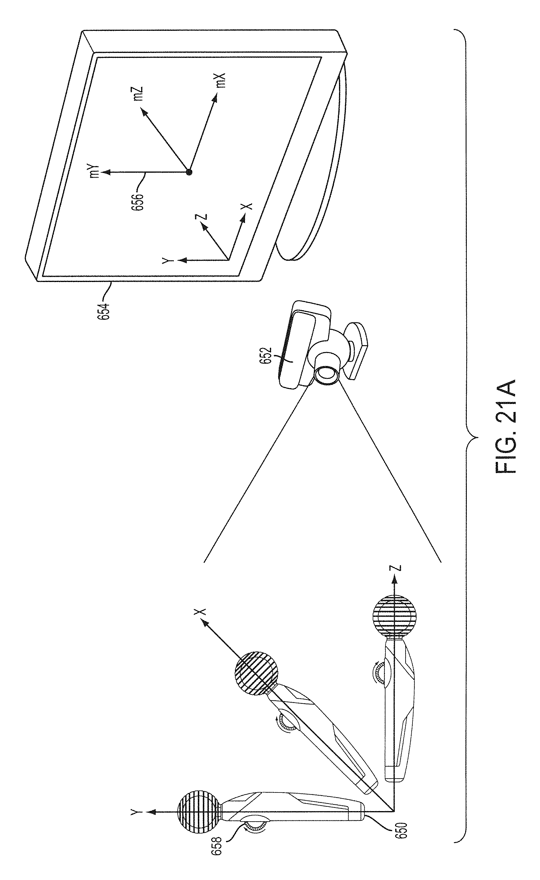
D00025

D00026

D00027

D00028

D00029

XML
uspto.report is an independent third-party trademark research tool that is not affiliated, endorsed, or sponsored by the United States Patent and Trademark Office (USPTO) or any other governmental organization. The information provided by uspto.report is based on publicly available data at the time of writing and is intended for informational purposes only.
While we strive to provide accurate and up-to-date information, we do not guarantee the accuracy, completeness, reliability, or suitability of the information displayed on this site. The use of this site is at your own risk. Any reliance you place on such information is therefore strictly at your own risk.
All official trademark data, including owner information, should be verified by visiting the official USPTO website at www.uspto.gov. This site is not intended to replace professional legal advice and should not be used as a substitute for consulting with a legal professional who is knowledgeable about trademark law.