Recognition system for an apparatus that delivers breathable gas to a patient
Kwok
U.S. patent number 10,279,134 [Application Number 14/862,596] was granted by the patent office on 2019-05-07 for recognition system for an apparatus that delivers breathable gas to a patient. This patent grant is currently assigned to ResMed Limited. The grantee listed for this patent is ResMed Limited. Invention is credited to Philip Rodney Kwok.


View All Diagrams
| United States Patent | 10,279,134 |
| Kwok | May 7, 2019 |
Recognition system for an apparatus that delivers breathable gas to a patient
Abstract
An adapter for use with a flow generator includes a conduit attachable to the outlet of the flow generator and an identifying element supported by the conduit and providing an identifying feature unique to a specific peripheral component attachable to the flow generator. The identifying feature is communicatable to the flow generator so that appropriate operating parameters of the flow generator may be automatically selected by the flow generator to coordinate with the specific peripheral component.
| Inventors: | Kwok; Philip Rodney (Chatswood, AU) | ||||||||||
|---|---|---|---|---|---|---|---|---|---|---|---|
| Applicant: |
|
||||||||||
| Assignee: | ResMed Limited (Bella Vista,
AU) |
||||||||||
| Family ID: | 36940769 | ||||||||||
| Appl. No.: | 14/862,596 | ||||||||||
| Filed: | September 23, 2015 |
Prior Publication Data
| Document Identifier | Publication Date | |
|---|---|---|
| US 20160008560 A1 | Jan 14, 2016 | |
Related U.S. Patent Documents
| Application Number | Filing Date | Patent Number | Issue Date | ||
|---|---|---|---|---|---|
| 13588556 | Aug 17, 2012 | 9162035 | |||
| 11794150 | Sep 18, 2012 | 8267084 | |||
| PCT/AU2006/000238 | Feb 24, 2006 | ||||
| 60656880 | Mar 1, 2005 | ||||
| Current U.S. Class: | 1/1 |
| Current CPC Class: | A61M 16/0066 (20130101); A61M 16/0816 (20130101); A61M 16/0069 (20140204); A61M 16/0875 (20130101); A61M 16/16 (20130101); A61M 2205/6045 (20130101); A61M 2205/6018 (20130101); A61M 2205/15 (20130101); A61M 2205/60 (20130101); A61M 2205/6027 (20130101); A61M 2205/3334 (20130101) |
| Current International Class: | A61M 16/00 (20060101); A61M 16/08 (20060101); A61M 16/16 (20060101) |
References Cited [Referenced By]
U.S. Patent Documents
| 2598978 | June 1952 | Martin |
| 4695955 | September 1987 | Faisandier |
| 4768496 | September 1988 | Kreizman et al. |
| 4883051 | November 1989 | Westenskow |
| 4944310 | July 1990 | Sullivan |
| 5072728 | December 1991 | Pasternack |
| 5293865 | March 1994 | Altner |
| 5413097 | May 1995 | Birenhelde et al. |
| 5490502 | February 1996 | Rapoport et al. |
| 5503146 | April 1996 | Froehlich et al. |
| 5660567 | August 1997 | Nierlich et al. |
| 5813404 | September 1998 | Devlin et al. |
| 5844862 | December 1998 | Cocatre-Zilgien |
| 5895595 | April 1999 | Haden |
| 5950621 | September 1999 | Klockseth |
| 6035851 | March 2000 | Wallen |
| 6085747 | July 2000 | Axe et al. |
| 6119686 | September 2000 | Somerson et al. |
| 6126610 | October 2000 | Rich et al. |
| 6142949 | November 2000 | Ubby |
| 6158430 | December 2000 | Pfeiffer et al. |
| 6186140 | February 2001 | Hoague |
| 6360741 | March 2002 | Truschel |
| 6363933 | April 2002 | Berthon-Jones |
| 6425395 | July 2002 | Brewer et al. |
| 6546930 | April 2003 | Emerson et al. |
| 6678215 | January 2004 | Treyz et al. |
| 6910483 | June 2005 | Daly et al. |
| 6953354 | October 2005 | Edirisuriya et al. |
| 7148806 | December 2006 | Antitila |
| 7314451 | January 2008 | Halperin et al. |
| RE40365 | June 2008 | Kirchgeorg et al. |
| 7424889 | September 2008 | Mashak |
| 7469698 | December 2008 | Childers et al. |
| 7527053 | May 2009 | DeVries et al. |
| 7607437 | October 2009 | Boyle et al. |
| 7891353 | February 2011 | Chalvignac |
| 7913689 | March 2011 | Henry et al. |
| 7987847 | August 2011 | Wickham et al. |
| 7997885 | August 2011 | Allum |
| 8006691 | August 2011 | Kenyon et al. |
| 8186345 | May 2012 | Payton et al. |
| 8210173 | July 2012 | Schermeier et al. |
| 8267084 | September 2012 | Kwok |
| 8381725 | February 2013 | Chalvignac |
| 8424514 | April 2013 | Oates |
| 9162035 | October 2015 | Kwok |
| 2001/0017134 | August 2001 | Bahr |
| 2002/0022973 | February 2002 | Sun et al. |
| 2002/0088464 | July 2002 | Truschel |
| 2002/0144682 | October 2002 | Kurger et al. |
| 2002/0174867 | November 2002 | Gunaratnam et al. |
| 2003/0076745 | April 2003 | Chapman |
| 2003/0140924 | July 2003 | Aylsworth et al. |
| 2003/0154981 | August 2003 | Spruiell |
| 2003/0187525 | October 2003 | Mann et al. |
| 2003/0196662 | October 2003 | Ging et al. |
| 2003/0208465 | November 2003 | Yurko et al. |
| 2003/0236450 | December 2003 | Kocinski |
| 2004/0074495 | April 2004 | Wickham et al. |
| 2004/0118403 | June 2004 | O'Connor et al. |
| 2004/0163647 | August 2004 | Figley et al. |
| 2004/0171982 | September 2004 | Danchin |
| 2004/0182386 | September 2004 | Meier |
| 2004/0210151 | October 2004 | Tsukashima et al. |
| 2004/0226566 | November 2004 | Gunaratnam et al. |
| 2005/0061318 | March 2005 | Faram |
| 2005/0076906 | April 2005 | Johnson |
| 2005/0114182 | May 2005 | Randolph et al. |
| 2005/0211761 | September 2005 | Anttila et al. |
| 2006/0231092 | October 2006 | Mashak |
| 2006/0278220 | December 2006 | Schermeier et al. |
| 2007/0000491 | January 2007 | Chalvignac |
| 2007/0144519 | June 2007 | Henry |
| 2008/0078387 | April 2008 | Vandine |
| 2009/0120437 | May 2009 | Oates |
| 2010/0147301 | July 2010 | Kwok |
| 2010/0236552 | September 2010 | Kwok et al. |
| 2011/0139153 | June 2011 | Chalvignac |
| 2011/0139154 | June 2011 | Henry et al. |
| 2012/0304994 | December 2012 | Kwok |
| 2012/0318266 | December 2012 | Chou |
| 2013/0206143 | August 2013 | Oates et al. |
| 40 20 522 | Jan 1992 | DE | |||
| 1 127 583 | Aug 2001 | EP | |||
| 1127583 | Jul 2003 | EP | |||
| 1 449 558 | Aug 2004 | EP | |||
| 1 516 641 | Mar 2005 | EP | |||
| 1 579 884 | Sep 2005 | EP | |||
| H04-158856 | Jun 1992 | JP | |||
| 6-23051 | Feb 1994 | JP | |||
| 2002-172170 | Jun 2002 | JP | |||
| 2003-061977 | Mar 2003 | JP | |||
| 2004-532666 | Oct 2004 | JP | |||
| WO 96/28093 | Sep 1996 | WO | |||
| 1997/006843 | Feb 1997 | WO | |||
| 2001/000264 | Jan 2001 | WO | |||
| 2001/32069 | May 2001 | WO | |||
| 2001-91841 | Dec 2001 | WO | |||
| 2002/053217 | Jul 2002 | WO | |||
| 2004/049912 | Jun 2004 | WO | |||
| 2004-060443 | Jul 2004 | WO | |||
| 2004-112873 | Dec 2004 | WO | |||
| 2005/002655 | Jan 2005 | WO | |||
| 2005/011556 | Feb 2005 | WO | |||
| WO 2005/037355 | Apr 2005 | WO | |||
| 2005/067520 | Jul 2005 | WO | |||
| WO 2006/092001 | Sep 2006 | WO | |||
| 2006-125252 | Nov 2006 | WO | |||
| 2007-059810 | Mar 2007 | WO | |||
| WO 2007/041797 | Apr 2007 | WO | |||
Other References
|
Second Amended Counterstatement in NZ Application No. 700746 dated Dec. 12, 2017 (17 pages). cited by applicant . Letter from The New Zealand Intellectual Property Office dated Jan. 26, 2016, granting an Extension of Time and forwarding an Application for Extension of Time and a Notice of Opposition to Grant of Patent (Section 21) filed Jan. 25, 2016, in a related New Zealand Application No. 700746, and (4 pages). cited by applicant . A Statement of Case filed Mar. 29, 2016, in a related New Zealand Application No. 700746 (16 pages). cited by applicant . Letter from the New Zealand Intellectual Property Office dated Apr. 1, 2016, forwarding a First Amended Notice of Opposition to Grant of Patent (Section 21) filed Mar. 29, 2016, in a related New Zealand Application No. 700746 (3 pages). cited by applicant . Affirmation of Ian Douglas Makinson, Mar. 3, 2017 (312 pages). cited by applicant . Affirmation of Alex Young, Mar. 3, 2017 (12 pages). cited by applicant . Affirmation of Craig Seddon Rothwell, Mar. 3, 2017 (64 pages). cited by applicant . Amended Statement of Case filed Feb. 3, 2017 (17 pages). cited by applicant . Affirmation of Ian Douglas Makinson, Jan. 26, 2017 (14 pages). cited by applicant . Affirmation of Andrew Baden Clark, Feb. 3, 2017 (14 pages). cited by applicant . Affirmation of Andrew Michael Baker, Feb. 3, 2017 (26 pages). cited by applicant . Amended Counterstatement, Jun. 26, 2017, (14 pages). cited by applicant . Claims filed in New Zealand Application No. 700746, Jun. 26, 2017 (3 pages). cited by applicant . Amended Notice of Opposition to Grant of Patent and Statement of Case issued Feb. 29, 2012 for corresponding New Zealand Application No. 567371. cited by applicant . International Search Report for PCT/AU2006/001506 dated Jan. 30, 2007. cited by applicant . Written Opinion of the International Searching Authority for PCT/AU2006/001506, dated Jan. 30, 2007. cited by applicant . International Preliminary Report on Patentability for PCT/AU2006/001506, dated Jan. 30, 2007. cited by applicant . Amended Notice of Opposition to Grant a Patent, filed on Jan. 28, 2014 in New Zealand Application No. 591993. cited by applicant . Statement of Case, filed on Jan. 28, 2014 in New Zealand Application No. 591993. cited by applicant . "Alarm Clock" The Penguin English Dictionary. 2007. http://www.credoreference.com/entry/penguineng/alarm_clock (Sep. 30, 2013). cited by applicant . Second Amended Notice of Opposition to Grant a Patent, filed on Jul. 18, 2014 in New Zealand Application No. 591993. cited by applicant . Amended Statement of Case, filed on Jul. 18, 2014 in New Zealand Application No. 591993. cited by applicant . Second Amended Statement of Case, filed on Sep. 29, 2014 in New Zealand Application No. 591993. cited by applicant . Statutory Declaration of Alex Young filed on Sep. 29, 2014 in New Zealand Application No. 591993. cited by applicant . Statutory Declaration of Andrew Baden Clark filed on Sep. 29, 2014 in New Zealand Application No. 591993. cited by applicant . Statutory Declaration of David Robin Whiting filed on Sep. 29, 2014 in New Zealand Application No. 591993. cited by applicant . Amended Counterstatement, filed on Aug. 21, 2014 in New Zealand Application No. 591993. cited by applicant . Statutory Declaration of Andrew Baden Clark, filed on Sep. 8, 2014 in New Zealand Application No. 600480. cited by applicant . Statutory Declaration of Haydn Llewellyn, filed on Sep. 8, 2014 in New Zealand Application No. 600480. cited by applicant . Second Amended Notice of Opposition to Grant a Patent, filed on Sep. 8, 2014 in New Zealand Application No. 600480. cited by applicant . Amended Statement of Case, filed on Sep. 8, 2014 in New Zealand Application No. 600480. cited by applicant . Amended Counterstatement, filed on Oct. 15, 2014 in New Zealand Application No. 600480. cited by applicant . Third Amended Notice of Opposition to Grant of Patent, filed on Oct. 21, 2014 in New Zealand Application No. 591993567. cited by applicant . Third Amended Statement of Case, filed on Oct. 21, 2014 in New Zealand Application No. 591993. cited by applicant . Statutory Declaration of Ian Malcolm Smith filed on May 28, 2015 in New Zealand Application No. 591993. cited by applicant . Statutory Declaration of Professor Geoffrey Mark Shaw filed on May 28, 2015 in New Zealand Application No. 591993. cited by applicant . Statutory Declaration of Haydn Llewellyn filed on Sep. 25, 2015 in New Zealand Application No. 591993. cited by applicant . Affirmation of Yi-Cheng Sun filed on Feb. 9, 2016 in New Zealand Application No. 591993. cited by applicant . Affirmation of Dr. David Maurice Rapoport filed on Feb. 9, 2016 in New Zealand Application No. 591993. cited by applicant . First Amended Notice of Opposition to Grant of Patent, filed on Mar. 29, 2016 in New Zealand Application No. 700746. cited by applicant . Amended Statement of Case No. NZ 700746 dated Mar. 2, 2017. cited by applicant . Proceeding Correspondence in NZ Appln. No. 591993 dated Oct. 30, 2017 (1 page). cited by applicant . Applicant's Response to Examiners Report on Latest Proposed Claim Amendments in NZ Appln. No. 591993 dated Oct. 24, 2017 (4 pages). cited by applicant . Amended Claims in Applicant's Response to Examiners Report on Latest Proposed Claim Amendments in NZ Appln. No. 591993 dated Oct. 24, 2017 (3 pages). cited by applicant . Examiners Report on Revised Proposed Claim Amendments in NZ Appln. No. 5919933 dated Sep. 25, 2017 (4 pages). cited by applicant . Proceeding Correspondence in NZ Appln. No. 700746 dated Oct. 3, 2017 (1 page). cited by applicant . Applicant's Response to Examiner Report on Proposed Claim Amendments in NZ Appln. No. 591993 dated Oct. 24, 2017 (4 pages). cited by applicant . Applicant's Response to Examiners Report on Proposed Claim Amendments in NZ Appln. No. 700746 dated Sep. 28, 2017 (1 page). cited by applicant . Amended Claims in Applicant's Response to Examiners Report on Proposed Claim Amendments in NZ Appln. No. 700746 dated Sep. 28, 2017 (3 pages). cited by applicant . Proceeding Correspondence in NZ Appln. No. 700746 dated Sep. 19, 2017 (2 pages). cited by applicant . Response to Examiner's Report in in NZ Appln. No. 591993 dated Aug. 18, 2017 (2 pages). cited by applicant . Amended Claims Response to Examiner's Report in in NZ Appln. No. 591993 dated Aug. 18, 2017 (3 pages). cited by applicant . Proceeding Correspondence in NZ Appln. No. 591993 dated Aug. 28, 2017 ( 1 page). cited by applicant . Proceeding Correspondence in NZ Appln. No. 591993 dated Jul. 20, 2017 (1 page). cited by applicant . Examiners Report on Amendments in Proceeding Correspondence in NZ Appln. No. 591993 dated Jul. 20, 2017 (2 pages). cited by applicant . Claims in Examiners Report on Amendments in Proceeding Correspondence in NZ Appln. No. 591993 dated Jul. 20, 2017 (3 pages). cited by applicant . Proceeding Correspondence in Amended Counterstatement in NZ Appln. No. 700746 dated Jun. 26, 2017 (1 page). cited by applicant . Amended Counterstatement in NZ Appln. No. 700746 dated Jun. 26, 2017 (14 pages). cited by applicant . Amended Claims in Amended Counterstatement in NZ Appln. No. 700746 dated Jun. 26, 2017 (3 pages). cited by applicant . Request for Change of Inventorship Declined in NZ Appln. No. 711441 dated Feb. 16, 2017 (2 pages). cited by applicant . Response to Request for Change of Inventorship Declined in NZ Appln. No. 711441 dated Feb. 27, 2017 (1 page). cited by applicant . Request for Change of Inventorship Declined in NZ Appln. No. 711441 dated Mar. 9, 2017 (1 pages). cited by applicant . Response to Declining of Change of Inventorship dated in NZ Appln. No. 711441 Mar. 14, 2017 (2 pages). cited by applicant . Correspondence re Correction of Error in NZ Appln. No. 711441 dated May 10, 2017 (2 pages). cited by applicant . Correspondence re Request for Correction of Error in NZ Appln. No. 711441 dated Mar. 30, 2017 (1 page). cited by applicant . Declaration in Support of Correspondence re Request for Correction of Error in NZ Appln. No. 711441 dated May 10, 2017 (2 pages). cited by applicant . Correspondence re Applicant's Proposed Claim Amendments in NZ Appln. No. 591993 dated May 15, 2017 (2 pages). cited by applicant . Applicant's Proposed Claim Amendments in NZ Appln. No. 591993 dated May 15, 2017 (3 pages). cited by applicant . First Examination Report in NZ Appln. No. 729116 dated May 22, 2017 (3 pages). cited by applicant . Further Examination Report in NZ Appln. No. 711441 dated May 22, 2017 (2 pages). cited by applicant . USPTO Patent Trial and Appeal Board in Case IPR2016-01723 dated Mar. 9, 2017 (18 pages). cited by applicant . International Search Report for PCT/AU2006/001169, dated Nov. 29, 2006. cited by applicant . Office Action for European Application No. 06126895.9, dated Oct. 29, 2012. cited by applicant . Office Action for U.S. Appl. No. 13/032,178, dated Feb. 6, 2014. cited by applicant . Kwok, U.S. Appl. No. 60/656,880, filed Mar. 1, 2005. cited by applicant . Kwok, U.S. Appl. No. 60/707,950, filed Aug. 15, 2006. cited by applicant . Japanese Office Action issued in JP 2006-344662 dated Nov. 22, 2011 with English Translation. cited by applicant . Examiner's First Report issued in related Australian Application No. 2006220222 (dated Nov. 8, 2010). cited by applicant . Office Action issued in related Japanese Application No. 2007-557276 (dated May 10, 2011) with English Translation. cited by applicant . Office Action issued in related European Application No. 06704913.0 (dated Oct. 20, 2011). cited by applicant . International Search Report for PCT/AU2006/000238 dated Apr. 26, 2006. cited by applicant . Supplementary Partial European Search Report for EP 06704913 dated Oct. 20, 2011. cited by applicant . International Preliminary Report on Patentability for PCT/AU/2006/000238 dated Sep. 11, 2007. cited by applicant . Written Opinion for PCT/AU2006/000238 dated Apr. 20, 2006. cited by applicant . 4.sup.th Amended Statement of Case in NZ appplication No. 591993 dated Apr. 13, 2018 (17 pages). cited by applicant . International Standard, IEC 60601-1-8, First Edition, dated Aug. 2003 (78 pages). cited by applicant . Pulmonetic Systems Innovations for Life, LTV Series Ventilators Operators Manual, dated Apr. 2004 (282 pages). cited by applicant . Proceeding Correspondence in Application No. 591993 dated Apr. 24, 2018 (2 pages). cited by applicant . Third Amended Notice of Opposition and Second Amended Statement of Case in NZ Application No. 700746 dated Jan. 23, 2018 (2 pages). cited by applicant . Second Amended Statement of Case dated Jan. 23, 2018 (20 pages). cited by applicant . Proceeding Correspondence in Application No. 591993 dated Jan. 31, 2018 (2 pages). cited by applicant . Response to Applicant's Proposed Amendments in Application No. 700746 dated Oct. 5, 2018 (4 pages). cited by applicant . Proceeding Correspondence in NZ Application No. 700746 dated Nov. 8, 2018 (3 pages). cited by applicant . Proceeding Correspondence in NZ Application No. 700746 dated Aug. 10, 2018 (3 pages). cited by applicant . Response to Applicant's Proposed Amendments in NZ Application No. 700746 dated Aug. 3, 2018 (2 pages). cited by applicant . First Examination Report in NZ Application No. 747190 dated Oct. 16, 2018 (3 pages). cited by applicant . Office Action in U.S. Appl. No. 14/665,192 dated Jul. 27, 2017 (26 pages). cited by applicant . U.S. Appl. No. 60/656,880, filed Mar. 1, 2005 (26 pages). cited by applicant . U.S. Appl. No. 60/703,432, filed Jul. 29, 2005 (26 pages). cited by applicant. |
Primary Examiner: Anderson; Gregory A
Assistant Examiner: Luarca; Margaret M
Attorney, Agent or Firm: Nixon & Vanderhye P.C.
Parent Case Text
CROSS REFERENCE TO RELATED APPLICATION
This application is a continuation of Ser. No. 13/588,556, filed Aug. 17, 2012, which is a divisional of application Ser. No. 11/794,150, filed Oct. 29, 2008 (now Pat. No. 8,267,084, issued Sep. 18, 2012), which is a national stage of International Application No. PCT/AU2006/000238, under 35 U.S.C. 371, filed Feb. 24, 2006, which claims the benefit of provisional Application No. 60/656,880, filed Mar. 1, 2005, the entire contents of each being hereby incorporated by reference in this application.
Claims
What is claimed is:
1. A continuous positive airway pressure (CPAP) system comprising: a flow generator configured to generate a supply of pressurized breathable gas that is delivered, via an airflow path that includes at least an outlet formed in the flow generator, a delivery conduit, and a patient interface, to a patient for treatment, the flow generator including a first connector structure; a peripheral CPAP component that is operable to be a component of the CPAP system and assist in application of treatment for the patient; a connector removably attachable to the first connector structure and separate from the peripheral CPAP component and, when attached, configured to communicate the pressurized breathable gas delivered from the outlet to other components included in the airflow path, the connector including an identifying element disposed on or in the connector with the identifying element including an identifying feature related to the peripheral CPAP component; an electronic controller electronically coupled to the first connector structure and configured to: automatically recognize, via the first connector structure, the peripheral CPAP component related to the connector when attached to the first connector structure based on the identifying feature; and automatically adjust at least one operating parameter of the flow generator based on recognition of the peripheral CPAP component, where adjustment of the operating parameter changes how the supply of pressurized breathable gas is delivered to the patient.
2. The CPAP system of claim 1, wherein the identifying feature includes data of at least one of the following: a log of patient use, an end of life service indication, components used during each use, and/or a leak parameter that indicates a measured leak value associated with the peripheral CPAP component.
3. The CPAP system of claim 1, wherein the connector has a tactile indicator used to assist in recognizing the peripheral component.
4. The CPAP system of claim 3, wherein the tactile indicator is a polygon or hexagon shape.
5. The CPAP system of claim 1, wherein the identifying feature includes an airflow related parameter of the peripheral CPAP component.
6. The CPAP system of claim 1, wherein the peripheral CPAP component is at least one of the patient interface, the delivery conduit, and a humidifier.
7. The CPAP system of claim 1, where the electronic controller is further configured to: responsive to recognition of the peripheral CPAP component as a first type of patient interface, set a pressure level of the pressurized breathable gas to a first level; and responsive to recognition of the peripheral CPAP component as a second type of patient interface, which is different from the first type of patient interface, set the pressure level of the pressurized breathable gas to a second level that is higher than the first level.
8. The CPAP system of claim 1, wherein the connector is configured to structurally couple the first connector structure to an end of the delivery conduit.
9. The CPAP system of claim 1, wherein a diameter of a first end of the connector is greater than a diameter of a second, opposing, end of the connector.
10. The CPAP system of claim 1, wherein the identifying element of the connector is a resistor and the identifying feature is a resistance of a resistor.
11. The CPAP system of claim 10, wherein the peripheral CPAP component is the patient interface and a particular resistance of the resistor is associated with a type of patient interface to which the patient interface belongs.
12. The CPAP system of claim 1, wherein the connector is configured to be electrically coupled to the first connector structure when attached.
Description
FIELD OF THE INVENTION
The present invention relates to an apparatus that delivers breathable gas to a patient.
BACKGROUND OF THE INVENTION
Apparatus to deliver breathable gas to a patient typically includes a flow generator, an air delivery conduit, and a patient interface. Prior to use, operating parameters of the flow generator, e.g., treatment pressure, need to be manually adjusted by the patient to coordinate with the peripheral components, e.g., patient interface, being used. For example, known flow generators include a menu system that allows the patient to select the type of peripheral components being used, e.g., by brand, method of delivery, etc. Once the components are selected by the patient, the flow generator can select appropriate operating parameters of the flow generator that best coordinate with the selected components.
The present invention provides improvements to known apparatus to facilitate the coordination between the flow generator and the peripheral components.
SUMMARY OF THE INVENTION
One aspect of the invention is directed towards a recognition system that provides structure to facilitate the coordination between the flow generator and the peripheral components.
Another aspect of the invention relates to an adapter for use with a flow generator that generates a supply of pressurized air to be provided at an outlet to a patient for treatment. The adapter includes a conduit attachable to the outlet of the flow generator, and an identifying element supported by the conduit and providing an identifying feature unique to a specific peripheral component attachable to the flow generator. The identifying feature is communicatable to the flow generator so that appropriate operating parameters of the flow generator may be automatically selected by the flow generator to coordinate with the specific peripheral component.
Other aspects, features, and advantages of this invention will become apparent from the following detailed description when taken in conjunction with the accompanying drawings, which are a part of this disclosure and which illustrate, by way of example, principles of this invention.
BRIEF DESCRIPTION OF THE DRAWINGS
The accompanying drawings facilitate, an understanding of the various embodiments of this invention. In such drawings:
FIG. 1 is a side view of an embodiment of an apparatus that delivers breathable gas to a patient, the apparatus including a recognition system constructed according to an embodiment of the present invention;
FIG. 2 is a top perspective view illustrating a flow generator incorporating the recognition system shown in FIG. 1, and one of the indicator lights being activated;
FIG. 3 is a top perspective view similar to FIG. 2 with another of the indicator lights being activated;
FIG. 4 is a front perspective view of the flow generator shown in FIG. 2 with an adapter of the recognition system removed;
FIG. 5 is an enlarged front perspective view of the flow generator shown in FIG. 4;
FIG. 6 is a schematic diagram of the flow generator and recognition system shown in FIG. 2;
FIG. 7 is a perspective view of an adapter of the recognition system shown in FIG. 2;
FIG. 8 is a perspective view, from a different angle, of the adapter shown in FIG. 7;
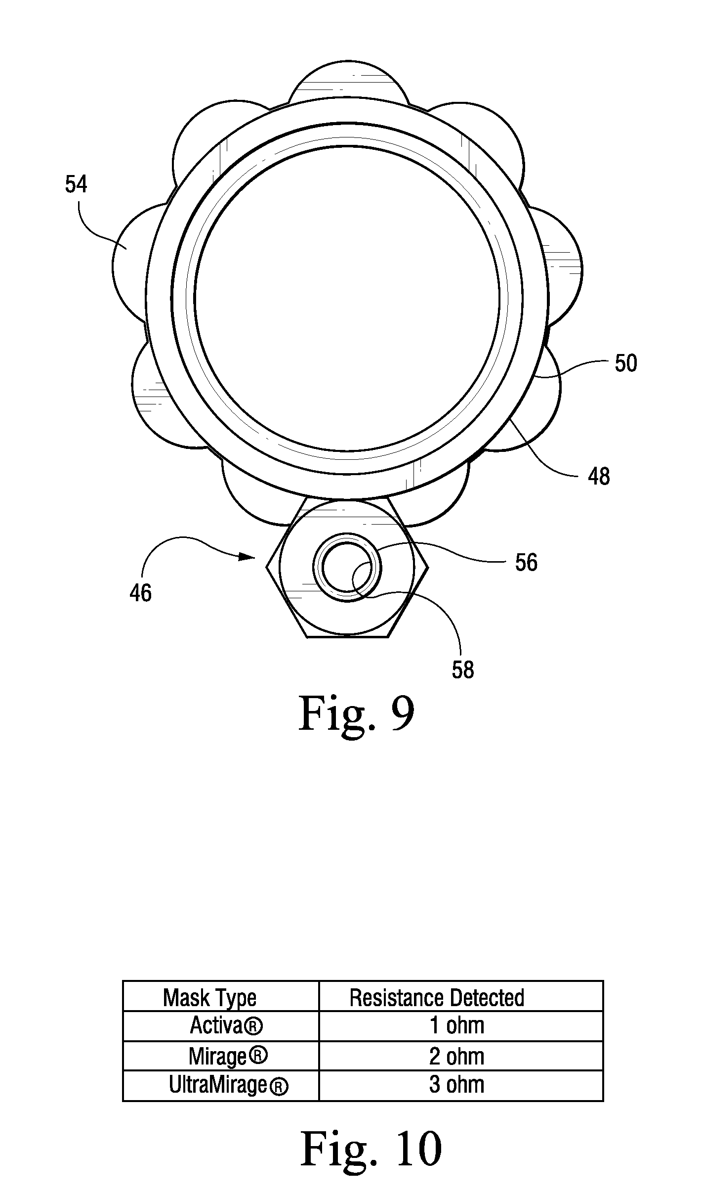
FIG. 9 is a top view of the adapter shown in FIG. 7;
FIG. 10 is a chart illustrating various magnitudes of resistance detected by the recognition system shown in FIG. 2 for embodiments of adapters associated with known masks sold by ResMed Ltd.;
FIG. 11 is a perspective view illustrating stacked adapters of the recognition system;
FIGS. 12 and 13 illustrate schematic side views of adapters/connectors according to further embodiments of the present invention;
FIG. 14 is a graph illustrating upper and lower ranges preferred by manufacturers of patient interfaces for flow vs. pressure; and
FIG. 15 is a flow chart illustrated an embodiment of a method for operating a flow generator.
DETAILED DESCRIPTION OF ILLUSTRATED EMBODIMENTS
FIGS. 1-9 illustrate a recognition system 10 constructed according to an embodiment of the present invention. The recognition system 10 is structured for use with an apparatus 12 that delivers a supply of pressurized breathable air to a patient for treatment, e.g., of Sleep Disordered Breathing (SDB) with CPAP or Non-Invasive Positive Pressure Ventilation (NIPPV). As best shown in FIG. 1, the apparatus 12 generally includes a flow generator 14, an air delivery conduit 16, and a patient interface 18. As discussed in greater detail below, the recognition system 10 allows the flow generator 14 to automatically recognize or identify one or more of the peripheral components selected by the patient so that appropriate operating parameters of the flow generator 14 may be automatically selected by the flow generator 14 to coordinate with the selected peripheral components.
The flow generator 14 is structured to generate a supply of pressurized air to be provided to a patient for treatment. The flow generator 14 includes a housing 20 and a blower 22 supported within the housing 20. As is known in the art, the blower 22 is operable to draw a supply of air into the housing 20 through one or more intake openings and provide a pressurized flow of air at an outlet 24 (see FIGS. 1, 4, and 5).
The supply of pressurized air is delivered to the patient via the air delivery conduit 16 that includes one end 26 coupled to the outlet 24 of the flow generator 14 and an opposite end 28 coupled to the patient interface 18, as shown in FIG. 1.
The patient interface 18 comfortably engages the patient's face and provides a seal. The patient interface 18 may have any suitable configuration as is known in the art, e.g., full-face mask, nasal mask, oro-nasal mask, mouth mask, nasal prongs, etc. Also, any suitable headgear arrangement 30 may be utilized to comfortably support the patient interface 18 in a desired position on the patient's face.
As best shown in FIGS. 2-4, the housing 20 of the flow generator 14 includes an upper wall 32, a lower wall 34, and side walls 36 that interconnect the upper and lower walls 32, 34. In the illustrated embodiment, the outlet 24 is provided in one of the side walls 36. Also, the upper wall 32 incorporates a manual control unit 38 for adjusting one or more parameters of the flow generator 14, e.g., treatment pressure. However, the outlet 24 and/or control unit 38 may be incorporated into any of the walls of the housing 20. Also, it should be understood that the flow generator 14 may include additional features incorporated into the housing 20, e.g., power supply.
As shown in FIG. 6, the flow generator 14 includes a controller 40 operable to receive input signals and to control operation of the blower 22 based on input signals. Input signals may be provided by the control unit 38 which has a plurality of control features that can be manually selected by the patient to adjust various parameters of the flow generator 14. For example, the patient may select the type of patient interface 18 being used, e.g., via a menu system of the control unit 38, so that the controller 40 can adjust the blower outlet pressure so that it coordinates with the selected patient interface 18. The controller 40 may include a memory 42 that stores preferred operating parameters for a variety of patient interfaces, e.g., by brand or method of delivery. When the controller 40 receives the input signal regarding the selected patient interface 18 from the control unit 38, the controller 40 can operate the blower 22 based on the stored operating parameters in the memory 42 for the selected patient interface 18. Alternatively, the preferred operating parameters for a selected patient interface 18 may be entered manually through the control unit 38.
Connector Recognition
The recognition system 10 is provided to allow the controller 40 of the flow generator 14 to automatically recognize one or more peripheral components, e.g., the patient interface 18, so that the patient does not have to utilize the control unit 38. Moreover, the recognition system 10 may allow the apparatus 12 to operate more efficiently as the recognition system 10 enables the flow generator 14 to select operating parameters that are specifically optimized for the selected peripheral components.
In the illustrated embodiment, the recognition system 10 includes a first connector portion 44 provided by the flow generator 14 (e.g., see FIGS. 4, 5, and 6), and a second connector portion 46 adapted to be removably coupled with the first connector portion 44 (e.g., see FIGS. 2, 3, and 6-9). The second connector portion 46 is associated with a specific peripheral component, e.g., patient interface 18, and includes an identifying feature unique to the specific peripheral component. The first connector portion 44 includes structure to communicate the identifying feature of the second connector portion 46 to the controller 40 so that the controller 40 can recognize the identifying feature and hence the associated peripheral component. The controller 40 can then select appropriate operating parameters of the blower 22, e.g., via memory 42, to coordinate with the associated peripheral component. For example, the blower 22 may be controlled so that the blower outlet pressure is relatively lower for one group of patient interfaces, e.g., nasal, and relatively higher for another group of patient interfaces, e.g., nasal and mouth.
As shown in FIGS. 2, 3, and 7-9, the second connector portion 46 is provided on an adapter 48 that is adapted to interconnect the outlet 24 of the flow generator 14 and the end 26 of the air delivery conduit 16. Specifically, the adapter 48 is in the form of a conduit including a first end portion 50 attachable to the outlet 24 and a second end portion 52 attachable to the air delivery conduit 16. As illustrated, first end portion 50 has a greater diameter than the second end portion 52. However, the end portions 50, 52 may have any suitable arrangement, e.g., similar diameters. Also, a gripping portion 54, in the form of spaced contoured ribs, is provided between the first and second end portions 50, 52 to facilitate connection.
As illustrated, the second connector portion 46 is mounted to the first end portion 50. As a result, the second connector portion 46 is able to removably couple with the first connector portion 44 on the flow generator 14 when the adapter 48 is coupled to the outlet 24. In the illustrated embodiment, the first connector portion 44 is in the form of a first conductor and the second connector portion 46 is in the form of a second conductor. Also, the second conductor 46 is bridged with an identifying element, in the form of a resistor, that provides the identifying feature unique to a specific peripheral component.
In use, the adapter 48 is attached to the outlet 24 so that the second conductor 46 is electrically coupled to the first conductor 44. In the illustrated embodiment, the second conductor includes a metallic pin 56 with an axially extending opening 58 and the first conductor includes a metallic pin 60. The axially extending opening 58 of the metallic pin 56 receives the metallic pin 60 therein to electrically couple the first and second conductors 44, 46. However, the first and second conductors 44, 46 may be electrically coupled in any other suitable manner. Once coupled, the controller 40 can detect the resistance provided by the resistor bridged with the second conductor 46. The resistance is unique to a particular peripheral component so the controller 40 can recognize the specific peripheral component by the resistance. Once recognized, the appropriate operating parameters of the flow generator 14 can be automatically selected by the controller 40 to coordinate with the specified peripheral component.
For example, FIG. 10 lists three known patient interfaces sold by ResMed Ltd. Each of the patient interfaces is supplied with an adapter 48 having a second connector portion 46 with a unique resistance value. In the illustrated embodiment, the Activa.RTM. has a resistor that provides resistance of about 1 ohm, the Mirage.RTM. has a resistor that provides resistance of about 2 ohm, and the UltraMirage.RTM. has a resistor that provides resistance of about 3 ohm. Accordingly, if the controller 40 detects a 2 ohm resistance when the adapter 48 and second connector portion 46 thereof is engaged with the flow generator 14, the controller 40 will recognize that the Mirage.RTM. is coupled to the flow generator 14 and select blower operating parameters that are optimized for the Mirage.RTM..
Thus, the recognition system 10 provides a "plug and play" arrangement wherein the patient can simply couple the adapter 48 and second connector portion thereof 46 to the flow generator 14 to automatically configure the flow generator 10 for a particular peripheral component, e.g., patient interface 18.
It should be understood that more than one peripheral component of the apparatus 12 may be provided with a unique adaptor 48 that automatically configures the flow generator 14 for the associated peripheral component. For example, an adapter 48 may be provided with each of the patient interface 18, air delivery conduit 16, and humidifier (not shown) coupled to the flow generator 14. Each adapter 48 would have a unique identifying feature, as described above, so that the controller 40 can recognize which components are coupled to the flow generator 14. Moreover, the controller 40 can optimize operation of the flow generator 14 to take into account the features of each of the patient interface 18, air delivery conduit 16, humidifier.
In one embodiment, the adapters 48 may be color coded to correspond with particular peripheral components. Moreover, the peripheral component may have a colored element that matches the color of the corresponding adapter 48. This allows the adapters 48 to be easily recognized and associated with the respective component. For example, a patient interface 18 may have a purple colored swivel connector that is accompanied by a purple colored adapter 48. When the purple colored adapter 48 is coupled to the flow generator 14, the controller 40 will optimize the flow generator 14 to correspond with the features of the purple colored patient interface 18. In addition, or in the alternative, the connector and/or peripheral component may have a tactile indicator such as shape, e.g., a polygon, hexagon, etc.
When multiple peripheral components are coupled to the flow generator 14, e.g., patient interface and humidifier, multiple adapters 48 may be stacked to the outlet 24 of the flow generator 14. For example, a purple adapter 48 associated with a patient interface 18 piggybacked to a yellow adapter 48 associated with a humidifier would signal the controller 40 that both a patient interface 18 and humidifier are attached to the flow generator 14. When piggybacked, one of the adapters 48A is coupled to the flow generator 14 as discussed above and the second adapter 48B is coupled to the first adapter 48A such that the first end portion 50 of the second adapter 48B is attachable to the second end portion 52 of the first adapter 48A and the second end portion 52 of the second adapter 48B is attachable to the air delivery conduit 16 as shown in FIG. 11. Moreover, the conductor 46 of the second adapter 48B is electrically coupled to a rear portion of the conductor 46 of the first adapter 48A. In one embodiment, the adapter 48B may be structured such that it cannot receive a plug from a downstream connector, rather it can only plug into the adapter 48A closer to the flow generator, so as to impose a limitation on the order of attachment. However, it is preferred that the adapters can be attached in random order, to facilitate the connector assembly operation.
The piggyback value of two resistor values wired in parallel could be recognized via simple electronics (e.g., 1/R Total=1/R.sub.1+1/R.sub.2, where R.sub.1 is the resistor value associated with the patient interface and R.sub.2 is the resistor value associated with the humidifier). The value of (1/R Total) would relate to a blower setting that adjusts the operating parameters to function optimally with the specific features of both the selected patient interface and humidifier. This arrangement eliminates user intervention to match peripheral components for optimal performance of the connected system.
It should be understood that the recognition system 10 may have any suitable structure to enable the controller 40 to automatically recognize selected peripheral components. In the illustrated embodiment, an adapter 48 incorporating an identifiable resistor is utilized to identify the peripheral component. However, the identifying element may have any suitable identifiable structure, e.g., impedance (e.g., using holes of various sizes), microswitches, infrared detectors, variable length pins, variable number of pins, variable pin mountings, spring loads, etc. For example, one embodiment may incorporate one or more variable length pins 46.1 on the end of the connector that can either incorporate a microswitch (or series of switches depending on length) or operate a variable resistor whose value is determined by the length of the pin, e.g., how far the pin pushes a lever operating variable resistor. A series of microswitches, e.g., 6 switches, located around the connector could be operated by pins 46.2 to either the on or off position, similar to a remote control. See, e.g., FIGS. 12 and 13.
Alternatively, the adaptor and/or a component thereof such as a pin may include a coded portion that encodes the flow generator with the peripheral component. This is similar to how a camera film housing encodes the camera with the camera film, upon loading of the housing into the camera.
In another embodiment, the second connector portion 46 may be provided as a separate key, separate from the adapter 48, that is engagable with the first connector portion 44 provided on the flow generator 14. Thus, the adapter 48 may be eliminated and the air delivery conduit 16 may connect directly to the outlet 24 of the flow generator 14.
Also, the controller 40 may identify the peripheral component in any suitable manner. That is, an identifying feature associated with the peripheral component may be communicated to the controller 40 in any suitable manner. For example, the identifying feature may be incorporated into the peripheral component, e.g., patient interface, itself and be communicated to the controller 40 via a wire extending from the peripheral component to the flow generator 14. Alternatively, the identifying feature may be communicated to the controller 40 wirelessly, e.g., RFID, IR, prismatic, smart card (computer chip). In "wireless" embodiments, the controller 40 would be coupled to a receiver adapted to receive signals transmitted by the identifying component associated with the peripheral component.
In another embodiment, the peripheral component may include a bar code with identifying information so that the peripheral component may be moved past a bar code reader provided on the flow generator 14 that will allow the controller 40 to identify the specific peripheral component being utilized.
Also, other information may be provided by the identifying component, e.g., a log of the patient's use, components used during each use, end of life service indication, etc.
The flow generator 14 may include one or more indicator lights to indicate that the peripheral components have been recognized and/or identified. For example, as shown in FIGS. 2 and 3, the flow generator 14 includes a red light 62 that indicates that the component has not yet been recognized (FIG. 2), and a green light 64 that indicates that the adapter 48 is connected and the associated component has been recognized. Thus, the indicator lights may provide positive feedback regarding connection and blower set-up status. The different lights may also indicate different peripherals and confirm correct alignment, e.g., one light for an Activa.RTM. mask, another light for an UltraMirage.RTM. Full Face Mask, etc.
In the illustrated embodiment, the adapter 48 must be properly aligned with the outlet 24 and the first connector portion 44 to enable the second connector portion 46 to couple with the first connector portion 44. However, the first and second connector portions 44, 46 may be configured and arranged so orientation of the adapter 48 with respect to the outlet 24 does not matter. Moreover, the flow generator will continue to operate even if one or more components of the recognition system are not employed, although the operating characteristics may not be optimized for the particular component in use.
The recognition system 10 is advantageous in that it allows the flow generator 14 to be optimized to function with the connected peripheral components. This minimizes patient intervention to setup the flow generator 14, and therefore improves ease of use.
Leak Testing on Manufacturer Line
Typically, manufacturers test manufactured patient interfaces on the manufacturing line for leak and require that they fall within upper and lower ranges in flow vs. pressure curve to ensure that each patient interface can be used with a flow generator. The flow vs. pressure curve measures for intended, e.g., vents, and Unintended sources of leak. Thus, a patient interface falling at A in FIG. 14 would be acceptable, and patient interfaces falling at B and C in FIG. 14 would not be acceptable. If a recognition system 10 is utilized, the leak testing results of the patient interface may be provided on an identifying component, e.g., smart card, and transferred to the controller 40 in use. FIG. 15 is a flow chart illustrating an exemplary method for operating a flow generator. With this information, the controller 40 can optimize the flow generator 14 to compensate for the measured operating parameter of the patient interface. That is, the specific parameters of the patient interface are compensated at the flow generator 14. This allows the typical range requirements to be eliminated so that masks falling at B and C in FIG. 14 can be utilized. Thus, manufacturing design constraints may be reduced, so that patient interfaces may be used that would not typically be used due to manufacturing standards.
While the invention has been described in connection with what are presently considered to be the most practical and preferred embodiments, it is to be understood that the invention is not to be limited to the disclosed embodiments, but on the contrary, is intended to cover various modifications and equivalent arrangements included within the spirit and scope of the invention.
* * * * *
References
D00000
D00001
D00002
D00003
D00004
D00005
D00006
D00007
D00008
D00009
D00010
D00011
XML
uspto.report is an independent third-party trademark research tool that is not affiliated, endorsed, or sponsored by the United States Patent and Trademark Office (USPTO) or any other governmental organization. The information provided by uspto.report is based on publicly available data at the time of writing and is intended for informational purposes only.
While we strive to provide accurate and up-to-date information, we do not guarantee the accuracy, completeness, reliability, or suitability of the information displayed on this site. The use of this site is at your own risk. Any reliance you place on such information is therefore strictly at your own risk.
All official trademark data, including owner information, should be verified by visiting the official USPTO website at www.uspto.gov. This site is not intended to replace professional legal advice and should not be used as a substitute for consulting with a legal professional who is knowledgeable about trademark law.