Ball and socket implants for correction of hammer toes and claw toes
Sander , et al.
U.S. patent number 10,278,828 [Application Number 15/337,275] was granted by the patent office on 2019-05-07 for ball and socket implants for correction of hammer toes and claw toes. This patent grant is currently assigned to Wright Medical Technology, Inc.. The grantee listed for this patent is Wright Medical Technology, Inc.. Invention is credited to Christine M. Petteys, Elizabeth Sander, Brian Thoren.


View All Diagrams
| United States Patent | 10,278,828 |
| Sander , et al. | May 7, 2019 |
Ball and socket implants for correction of hammer toes and claw toes
Abstract
A toe bone implant for correction of toe bone deformities is provided. The toe bone implant includes a first portion having a socket portion. The toe bone implant also includes a second portion having a ball portion operatively connected to the socket portion. The toe bone implant is implanted in a joint such that the ball portion is configured to rotate a predetermined amount respective to the socket portion.
| Inventors: | Sander; Elizabeth (Memphis, TN), Petteys; Christine M. (Bartlett, TN), Thoren; Brian (Memphis, TN) | ||||||||||
|---|---|---|---|---|---|---|---|---|---|---|---|
| Applicant: |
|
||||||||||
| Assignee: | Wright Medical Technology, Inc.
(Memphis, TN) |
||||||||||
| Family ID: | 49886786 | ||||||||||
| Appl. No.: | 15/337,275 | ||||||||||
| Filed: | October 28, 2016 |
Prior Publication Data
| Document Identifier | Publication Date | |
|---|---|---|
| US 20170042691 A1 | Feb 16, 2017 | |
Related U.S. Patent Documents
| Application Number | Filing Date | Patent Number | Issue Date | ||
|---|---|---|---|---|---|
| 14560265 | Dec 4, 2014 | 9504582 | |||
| 13839573 | Feb 3, 2015 | 8945232 | |||
| 61747429 | Dec 31, 2012 | ||||
| Current U.S. Class: | 1/1 |
| Current CPC Class: | A61F 2/4225 (20130101); A61F 2/4241 (20130101); A61F 2002/4243 (20130101); A61F 2002/30662 (20130101); A61F 2002/30649 (20130101); A61F 2002/4228 (20130101); A61F 2002/30062 (20130101); A61F 2002/4251 (20130101); A61F 2002/30672 (20130101); A61F 2002/30607 (20130101); A61F 2002/4233 (20130101) |
| Current International Class: | A61F 2/42 (20060101); A61F 2/30 (20060101) |
References Cited [Referenced By]
U.S. Patent Documents
| 321389 | June 1885 | Schirmer |
| 346148 | July 1886 | Durham |
| 348589 | September 1886 | Sloan |
| 373074 | November 1887 | Jones |
| 430236 | June 1890 | Rogers |
| 561968 | June 1896 | Coulon |
| 736121 | August 1903 | Lipscomb |
| 821025 | May 1906 | Davies |
| 882937 | March 1908 | Pegley |
| 1966835 | July 1934 | Stites |
| 2140749 | December 1938 | Kaplan |
| 2361107 | October 1944 | Johnson |
| 2451747 | October 1948 | Kindt |
| 2490364 | December 1949 | Livingston |
| 2600517 | June 1952 | Rushing |
| 2697370 | December 1954 | Brooks |
| 2832245 | April 1958 | Burrows |
| 2895368 | July 1959 | Place |
| 3462765 | August 1969 | Swanson |
| 3466669 | September 1969 | Flatt |
| 3593342 | July 1971 | Niebauer et al. |
| 3681786 | August 1972 | Lynch |
| 3739403 | June 1973 | Nicolle |
| 3759257 | September 1973 | Fischer et al. |
| 3760802 | September 1973 | Fischer et al. |
| 3779239 | December 1973 | Fischer et al. |
| 3824631 | July 1974 | Burstein et al. |
| D243716 | March 1977 | Treace et al. |
| 4047524 | September 1977 | Hall |
| 4096896 | June 1978 | Engel |
| 4156296 | May 1979 | Johnson et al. |
| 4170990 | October 1979 | Baumgart et al. |
| 4175555 | November 1979 | Herbert |
| 4198713 | April 1980 | Swanson |
| 4204284 | May 1980 | Koeneman |
| 4213208 | July 1980 | Marne |
| 4237875 | December 1980 | Termanini |
| 4262665 | April 1981 | Roalstad et al. |
| 4263903 | April 1981 | Griggs |
| 4275717 | June 1981 | Bolesky |
| 4276660 | July 1981 | Laure |
| 4278091 | July 1981 | Borzone |
| 4304011 | December 1981 | Whelan, III |
| 4321002 | March 1982 | Froehlich |
| 4364382 | December 1982 | Mennen |
| 4367562 | January 1983 | Gauthier |
| 4404874 | September 1983 | Lieser |
| 4434796 | March 1984 | Karapetian et al. |
| 4454875 | June 1984 | Pratt et al. |
| 4485816 | December 1984 | Krumme |
| D277509 | February 1985 | Lawrence et al. |
| D277784 | February 1985 | Sgariato et al. |
| 4516569 | May 1985 | Evans et al. |
| 4570623 | February 1986 | Ellison et al. |
| 4590928 | May 1986 | Hunt et al. |
| D284099 | June 1986 | Laporta et al. |
| 4634382 | January 1987 | Kusano et al. |
| 4642122 | February 1987 | Stefee |
| 4655661 | April 1987 | Brandt |
| D291731 | September 1987 | Alkins |
| 4723540 | February 1988 | Gilmer, Jr. |
| 4723541 | February 1988 | Reese |
| 4731087 | March 1988 | Sculco et al. |
| 4756711 | July 1988 | Mai et al. |
| 4759768 | July 1988 | Hermann et al. |
| 4790304 | December 1988 | Rosenberg |
| 4865606 | September 1989 | Rehder |
| 4908031 | March 1990 | Frisch |
| 4915092 | April 1990 | Firica et al. |
| 4932974 | June 1990 | Pappas et al. |
| 4940467 | July 1990 | Tronzo |
| 4955916 | September 1990 | Carignan et al. |
| 4963144 | October 1990 | Huene |
| 4969909 | November 1990 | Barouk |
| 5002563 | March 1991 | Pyka et al. |
| 5007932 | April 1991 | Bekki et al. |
| 5011497 | April 1991 | Persson et al. |
| 5019079 | May 1991 | Ross |
| 5029753 | July 1991 | Hipon et al. |
| 5037440 | August 1991 | Koenig |
| 5046513 | September 1991 | Gatturna et al. |
| 5047059 | September 1991 | Saffar |
| 5053038 | October 1991 | Sheehan |
| 5059193 | October 1991 | Kuslich |
| 5062851 | November 1991 | Branemark |
| 5089009 | February 1992 | Green |
| 5092896 | March 1992 | Meuli et al. |
| 5108395 | April 1992 | Laurain |
| 5133761 | July 1992 | Krouskop |
| 5147363 | September 1992 | Harle |
| 5171252 | December 1992 | Friedland |
| 5179915 | January 1993 | Cohen et al. |
| 5190546 | March 1993 | Jervis |
| 5199839 | April 1993 | DeHaitre |
| 5207712 | May 1993 | Cohen |
| 5209756 | May 1993 | Seedhom et al. |
| 5213347 | May 1993 | Rulon et al. |
| 5222975 | June 1993 | Crainich |
| 5246443 | September 1993 | Mai |
| 5281225 | January 1994 | Vicenzi |
| 5304204 | April 1994 | Bregen |
| 5324307 | June 1994 | Jarrett et al. |
| 5326364 | July 1994 | Clift, Jr. et al. |
| 5326366 | July 1994 | Pascarella et al. |
| 5330476 | July 1994 | Hiot et al. |
| 5342396 | August 1994 | Cook |
| 5352229 | October 1994 | Goble et al. |
| 5354301 | October 1994 | Catellano |
| 5358405 | October 1994 | Imai |
| 5360450 | November 1994 | Giannini |
| 5366479 | November 1994 | McGarry et al. |
| 5380334 | January 1995 | Torrie et al. |
| 5395372 | March 1995 | Holt et al. |
| 5405400 | April 1995 | Linscheid et al. |
| 5405401 | April 1995 | Lippincott, III et al. |
| 5417692 | May 1995 | Goble et al. |
| 5425776 | June 1995 | Cohen |
| 5425777 | June 1995 | Sarkisian et al. |
| 5437674 | August 1995 | Worcel et al. |
| 5449359 | September 1995 | Groiso |
| 5454814 | October 1995 | Comte |
| 5458648 | October 1995 | Berman et al. |
| 5470230 | November 1995 | Daftary et al. |
| 5474557 | December 1995 | Mai |
| 5480447 | January 1996 | Skiba |
| 5484443 | January 1996 | Pascarella et al. |
| 5498265 | March 1996 | Asnis et al. |
| 5507822 | April 1996 | Bouchon et al. |
| 5516248 | May 1996 | DeHaitre |
| 5522903 | June 1996 | Sokolow et al. |
| 5529075 | June 1996 | Clark |
| 5536127 | July 1996 | Pennig |
| 5549681 | August 1996 | Segmuller et al. |
| 5551871 | September 1996 | Besselink et al. |
| 5554157 | September 1996 | Errico et al. |
| 5578034 | November 1996 | Estes |
| 5591165 | January 1997 | Jackson |
| 5595563 | January 1997 | Moisdon |
| 5601558 | February 1997 | Torrie et al. |
| D378409 | March 1997 | Michelson |
| 5634925 | June 1997 | Urbanski |
| 5643264 | July 1997 | Sherman et al. |
| 5645599 | July 1997 | Samani |
| 5660188 | August 1997 | Groiso |
| 5669913 | September 1997 | Zobel |
| 5674297 | October 1997 | Lane et al. |
| 5683466 | November 1997 | Vitale |
| 5690629 | November 1997 | Asher et al. |
| 5702472 | December 1997 | Huebner |
| 5707395 | January 1998 | Li |
| 5713903 | February 1998 | Sander et al. |
| 5713904 | February 1998 | Errico et al. |
| 5720753 | February 1998 | Sander et al. |
| 5725585 | March 1998 | Zobel |
| 5728127 | March 1998 | Asher et al. |
| 5733307 | March 1998 | Dinsdale |
| 5741256 | April 1998 | Bresina |
| 5749916 | May 1998 | Richelsoph |
| 5769852 | June 1998 | Branemark |
| 5776202 | July 1998 | Copf et al. |
| 5779707 | July 1998 | Bertholet et al. |
| 5782927 | July 1998 | Klawittler et al. |
| 5785713 | July 1998 | Jobe |
| 5840078 | November 1998 | Yerys |
| 5853414 | December 1998 | Groiso |
| 5876434 | March 1999 | Flomenblit et al. |
| 5882444 | March 1999 | Flomenblit et al. |
| 5893850 | April 1999 | Cachia |
| 5919193 | July 1999 | Slavitt |
| 5928236 | July 1999 | Augagneur et al. |
| 5941890 | August 1999 | Voegele et al. |
| 5951288 | September 1999 | Sawa |
| 5958159 | September 1999 | Prandi |
| 5980524 | November 1999 | Justin et al. |
| 5984970 | November 1999 | Bramlet |
| 5984971 | November 1999 | Faccioli et al. |
| 6011497 | January 2000 | Tsang et al. |
| 6017366 | January 2000 | Berman |
| 6030162 | February 2000 | Huebner |
| 6045573 | April 2000 | Wenstrom, Jr. et al. |
| 6048151 | April 2000 | Kwee |
| 6048343 | April 2000 | Mathis et al. |
| 6083242 | July 2000 | Cook |
| 6099571 | August 2000 | Knapp |
| 6102642 | August 2000 | Kawashita et al. |
| 6146387 | November 2000 | Trott et al. |
| 6187009 | February 2001 | Herzog et al. |
| 6193757 | February 2001 | Foley et al. |
| 6197037 | March 2001 | Hair |
| 6200321 | March 2001 | Orbay et al. |
| 6200330 | March 2001 | Benderev et al. |
| 6200345 | March 2001 | Morgan |
| 6224600 | May 2001 | Protogirou |
| 6248109 | June 2001 | Stofella |
| 6299613 | October 2001 | Ogilvie et al. |
| 6305053 | October 2001 | Galbreath |
| 6306140 | October 2001 | Siddiqui |
| 6319284 | November 2001 | Rushdy et al. |
| 6332885 | December 2001 | Martella |
| 6336928 | January 2002 | Guerin et al. |
| 6352560 | March 2002 | Poeschmann et al. |
| 6383223 | May 2002 | Baehler et al. |
| 6386877 | May 2002 | Sutter |
| 6406234 | June 2002 | Frigg |
| 6413260 | July 2002 | Berrevoets et al. |
| 6419706 | July 2002 | Graf |
| 6423097 | July 2002 | Rauscher |
| 6428634 | August 2002 | Besselink et al. |
| 6436099 | August 2002 | Drewry et al. |
| 6451057 | September 2002 | Chen et al. |
| 6454808 | September 2002 | Masada |
| 6458134 | October 2002 | Songer et al. |
| 6475242 | November 2002 | Bramlet |
| 6508841 | January 2003 | Martin et al. |
| 6517543 | February 2003 | Berrevoets et al. |
| 6533788 | March 2003 | Orbay |
| 6551321 | April 2003 | Burkinshaw |
| 6551343 | April 2003 | Tormala et al. |
| 6575973 | June 2003 | Shekalim |
| 6575976 | June 2003 | Grafton |
| 6582453 | June 2003 | Tran et al. |
| 6648890 | November 2003 | Culbert et al. |
| 6679668 | January 2004 | Martin et al. |
| 6682565 | January 2004 | Krishnan |
| 6685706 | February 2004 | Padget et al. |
| 6699247 | March 2004 | Zucherman et al. |
| 6699292 | March 2004 | Ogilvie et al. |
| 6706045 | March 2004 | Lin et al. |
| 6767350 | July 2004 | Lob |
| 6773437 | August 2004 | Ogilvie et al. |
| 6811568 | November 2004 | Minamikawa |
| 6869449 | March 2005 | Ball et al. |
| 6875235 | April 2005 | Ferree |
| 7037309 | May 2006 | Weil et al. |
| 7037324 | May 2006 | Martinek |
| 7037342 | May 2006 | Nilsson et al. |
| 7041106 | May 2006 | Carver et al. |
| 7044953 | May 2006 | Capanni |
| 7112214 | September 2006 | Peterson et al. |
| 7182787 | February 2007 | Hassler et al. |
| 7192445 | March 2007 | Ellingsen et al. |
| 7207994 | April 2007 | Vlahos et al. |
| 7240677 | July 2007 | Fox |
| 7261716 | August 2007 | Strobel |
| 7291175 | November 2007 | Gordon |
| 7569061 | August 2009 | Colleran |
| 7585316 | September 2009 | Trieu |
| 7588603 | September 2009 | Leonard |
| 7695471 | April 2010 | Cheung et al. |
| 7708759 | May 2010 | Lubbers et al. |
| 7727235 | June 2010 | Contiliano et al. |
| 7780701 | August 2010 | Meridew et al. |
| 7780737 | August 2010 | Bonnard et al. |
| 7785357 | August 2010 | Guan et al. |
| 7837738 | November 2010 | Reigstad et al. |
| 7842091 | November 2010 | Johnstone et al. |
| 7887589 | February 2011 | Glenn et al. |
| 7909880 | March 2011 | Grant |
| 7918879 | April 2011 | Yeung et al. |
| 7959681 | June 2011 | Lavi |
| 7963995 | June 2011 | Richelsoph |
| 7976565 | July 2011 | Meridew |
| 7985246 | July 2011 | Trieu |
| 8002811 | August 2011 | Corradi et al. |
| 8057524 | November 2011 | Meridew |
| 8100983 | January 2012 | Schulte |
| 8118839 | February 2012 | Taylor |
| 8118849 | February 2012 | Wahl et al. |
| 8197509 | June 2012 | Contiliano et al. |
| 8262712 | September 2012 | Coilard-Lavirotte et al. |
| 8267939 | September 2012 | Cipoletti et al. |
| 8337537 | December 2012 | Pelo et al. |
| 8394097 | March 2013 | Peyrot et al. |
| 8394132 | March 2013 | Lewis et al. |
| 8414583 | April 2013 | Prandi et al. |
| 8465525 | June 2013 | Hawkins et al. |
| 8475456 | July 2013 | Augoyard et al. |
| 8523944 | September 2013 | Jiminez et al. |
| 8591545 | November 2013 | Lunn et al. |
| 8608785 | December 2013 | Reed et al. |
| 8616091 | December 2013 | Anderson |
| 8636457 | January 2014 | Connors |
| 8641769 | February 2014 | Malandain |
| 8647390 | February 2014 | Bellemere et al. |
| 8764842 | July 2014 | Graham |
| 8840677 | September 2014 | Kale et al. |
| 8888779 | November 2014 | Senn |
| D720072 | December 2014 | Cheney et al. |
| 8906060 | December 2014 | Hart |
| 8986386 | March 2015 | Oglaza et al. |
| 8998999 | April 2015 | Lewis et al. |
| 9044287 | June 2015 | Reed et al. |
| 9056014 | June 2015 | McCormick et al. |
| 9125704 | September 2015 | Reed et al. |
| 9138274 | September 2015 | Biesinger et al. |
| 9149268 | October 2015 | Graul et al. |
| 9474561 | October 2016 | Shemwell |
| 2001/0025199 | September 2001 | Rauscher |
| 2001/0028836 | October 2001 | Kohori |
| 2001/0049529 | December 2001 | Cachia et al. |
| 2002/0019636 | February 2002 | Ogilvie et al. |
| 2002/0022887 | February 2002 | Huene |
| 2002/0026194 | February 2002 | Morrison et al. |
| 2002/0055785 | May 2002 | Harris |
| 2002/0065561 | May 2002 | Ogilvie et al. |
| 2002/0068939 | June 2002 | Levy et al. |
| 2002/0072803 | June 2002 | Saunders et al. |
| 2002/0082705 | June 2002 | Bouman et al. |
| 2002/0111690 | August 2002 | Hyde |
| 2002/0128713 | September 2002 | Ferree |
| 2002/0165544 | November 2002 | Perren et al. |
| 2002/0183846 | December 2002 | Kuslich et al. |
| 2003/0032961 | February 2003 | Pelo et al. |
| 2003/0040805 | February 2003 | Minamikawa |
| 2003/0069645 | April 2003 | Ball et al. |
| 2003/0130660 | July 2003 | Levy et al. |
| 2003/0191422 | October 2003 | Sossong |
| 2003/0233095 | December 2003 | Urbanski et al. |
| 2004/0010315 | January 2004 | Song |
| 2004/0093081 | May 2004 | Nilsson et al. |
| 2004/0097941 | May 2004 | Weiner et al. |
| 2004/0102853 | May 2004 | Boumann et al. |
| 2004/0111117 | June 2004 | Colleran et al. |
| 2004/0133204 | July 2004 | Davies |
| 2004/0138756 | July 2004 | Reeder |
| 2004/0220574 | November 2004 | Pelo et al. |
| 2004/0220678 | November 2004 | Chow et al. |
| 2004/0230193 | November 2004 | Cheung et al. |
| 2004/0230194 | November 2004 | Urbanski et al. |
| 2004/0230313 | November 2004 | Saunders |
| 2004/0249461 | December 2004 | Ferree |
| 2005/0113836 | May 2005 | Lozier et al. |
| 2005/0119757 | June 2005 | Hassler et al. |
| 2005/0123672 | June 2005 | Justin et al. |
| 2005/0124443 | June 2005 | Summers |
| 2005/0149031 | July 2005 | Ciccone et al. |
| 2005/0177158 | August 2005 | Doubler et al. |
| 2005/0187636 | August 2005 | Graham |
| 2005/0251265 | November 2005 | Calandruccio et al. |
| 2005/0261768 | November 2005 | Trieu |
| 2005/0283159 | December 2005 | Amara |
| 2006/0052725 | March 2006 | Santilli |
| 2006/0052878 | March 2006 | Schmieding |
| 2006/0074421 | April 2006 | Bickley et al. |
| 2006/0074488 | April 2006 | Abdou |
| 2006/0074492 | April 2006 | Frey |
| 2006/0084998 | April 2006 | Levy et al. |
| 2006/0100715 | May 2006 | De Villiers |
| 2006/0129153 | June 2006 | Klaue et al. |
| 2006/0149258 | July 2006 | Sousa |
| 2006/0173462 | August 2006 | Kay et al. |
| 2006/0200151 | September 2006 | Ducharme et al. |
| 2006/0229617 | October 2006 | Meller et al. |
| 2006/0247787 | November 2006 | Rydell et al. |
| 2007/0038303 | February 2007 | Myerson et al. |
| 2007/0078518 | April 2007 | Lavi |
| 2007/0106283 | May 2007 | Garcia et al. |
| 2007/0123873 | May 2007 | Czartoski et al. |
| 2007/0123993 | May 2007 | Hassler et al. |
| 2007/0142920 | June 2007 | Niemi |
| 2007/0177959 | August 2007 | Chopp et al. |
| 2007/0185583 | August 2007 | Branemark |
| 2007/0185584 | August 2007 | Kaufmann et al. |
| 2007/0198018 | August 2007 | Biedermann et al. |
| 2007/0213831 | September 2007 | de Cubber |
| 2007/0239158 | October 2007 | Trieu et al. |
| 2007/0293866 | December 2007 | Stroeckel et al. |
| 2008/0039949 | February 2008 | Meesenburg et al. |
| 2008/0051912 | February 2008 | Hollawell |
| 2008/0086139 | April 2008 | Bourke et al. |
| 2008/0132894 | June 2008 | Coilard-Lavirotte et al. |
| 2008/0132958 | June 2008 | Pech et al. |
| 2008/0154385 | June 2008 | Trail et al. |
| 2008/0161919 | July 2008 | Melkent |
| 2008/0177262 | July 2008 | Augoyard et al. |
| 2008/0177291 | July 2008 | Jensen et al. |
| 2008/0177334 | July 2008 | Stinnette |
| 2008/0195215 | August 2008 | Morton |
| 2008/0195219 | August 2008 | Wiley et al. |
| 2008/0221574 | September 2008 | Cavallazzi |
| 2008/0221697 | September 2008 | Graser |
| 2008/0221698 | September 2008 | Berger |
| 2008/0255618 | October 2008 | Fisher et al. |
| 2008/0269908 | October 2008 | Warburton |
| 2008/0294204 | November 2008 | Chirico et al. |
| 2009/0005782 | January 2009 | Chirico et al. |
| 2009/0012564 | January 2009 | Chirico et al. |
| 2009/0036893 | February 2009 | Kartalian et al. |
| 2009/0149891 | June 2009 | Lee et al. |
| 2009/0163918 | June 2009 | Levy et al. |
| 2009/0187219 | July 2009 | Pachtman et al. |
| 2009/0204158 | August 2009 | Sweeney |
| 2009/0210016 | August 2009 | Champagne et al. |
| 2009/0216282 | August 2009 | Blake et al. |
| 2009/0254189 | October 2009 | Scheker |
| 2009/0254190 | October 2009 | Gannoe et al. |
| 2009/0259316 | October 2009 | Ginn et al. |
| 2010/0010637 | January 2010 | Pequignot |
| 2010/0016982 | January 2010 | Solomons |
| 2010/0023012 | January 2010 | Voor |
| 2010/0030221 | February 2010 | Christian et al. |
| 2010/0049244 | February 2010 | Cohen et al. |
| 2010/0057214 | March 2010 | Graham et al. |
| 2010/0061825 | March 2010 | Liu et al. |
| 2010/0069913 | March 2010 | Chirico |
| 2010/0069970 | March 2010 | Lewis et al. |
| 2010/0121390 | May 2010 | Kleinman |
| 2010/0125274 | May 2010 | Greenhalgh et al. |
| 2010/0131014 | May 2010 | Peyrot et al. |
| 2010/0131072 | May 2010 | Schulte |
| 2010/0161068 | June 2010 | Lindner et al. |
| 2010/0185295 | July 2010 | Emmanuel |
| 2010/0217325 | August 2010 | Hochschuler et al. |
| 2010/0249942 | September 2010 | Goswami et al. |
| 2010/0256639 | October 2010 | Tyber et al. |
| 2010/0256770 | October 2010 | Hakansson et al. |
| 2010/0262254 | October 2010 | Lawrence et al. |
| 2010/0274293 | October 2010 | Terrill et al. |
| 2010/0286692 | November 2010 | Greenhalgh et al. |
| 2010/0292799 | November 2010 | Hansell et al. |
| 2010/0324556 | December 2010 | Tyber et al. |
| 2010/0331893 | December 2010 | Geist et al. |
| 2011/0004255 | January 2011 | Weiner et al. |
| 2011/0004317 | January 2011 | Hacking et al. |
| 2011/0066190 | March 2011 | Schaller et al. |
| 2011/0082507 | April 2011 | Klaue |
| 2011/0082508 | April 2011 | Reed |
| 2011/0093017 | April 2011 | Prasad et al. |
| 2011/0093075 | April 2011 | Duplessis et al. |
| 2011/0093085 | April 2011 | Morton |
| 2011/0118739 | May 2011 | Tyber et al. |
| 2011/0144644 | June 2011 | Prandi et al. |
| 2011/0144766 | June 2011 | Kale et al. |
| 2011/0208252 | August 2011 | Erhart |
| 2011/0257652 | October 2011 | Roman |
| 2011/0301652 | December 2011 | Reed et al. |
| 2011/0301653 | December 2011 | Reed et al. |
| 2011/0306975 | December 2011 | Kaikkonen et al. |
| 2011/0319946 | December 2011 | Levy et al. |
| 2012/0016428 | January 2012 | White et al. |
| 2012/0065692 | March 2012 | Champagne et al. |
| 2012/0065738 | March 2012 | Schulman |
| 2012/0089197 | April 2012 | Anderson |
| 2012/0136448 | May 2012 | Seifert et al. |
| 2012/0209337 | August 2012 | Weinstein |
| 2012/0259419 | October 2012 | Brown et al. |
| 2012/0271362 | October 2012 | Martineau et al. |
| 2012/0323241 | December 2012 | McClellan et al. |
| 2013/0030475 | January 2013 | Weiner et al. |
| 2013/0053975 | February 2013 | Reed et al. |
| 2013/0060295 | March 2013 | Reed et al. |
| 2013/0066383 | March 2013 | Anderson et al. |
| 2013/0066435 | March 2013 | Averous et al. |
| 2013/0079776 | March 2013 | Zwirkoski et al. |
| 2013/0090655 | April 2013 | Tontz |
| 2013/0096634 | April 2013 | Suh |
| 2013/0123862 | May 2013 | Anderson et al. |
| 2013/0131822 | May 2013 | Lewis et al. |
| 2013/0150965 | June 2013 | Taylor et al. |
| 2013/0190761 | July 2013 | Prandi et al. |
| 2013/0211451 | August 2013 | Wales et al. |
| 2013/0226191 | August 2013 | Thoren et al. |
| 2013/0253597 | September 2013 | Augoyard et al. |
| 2013/0274814 | October 2013 | Weiner et al. |
| 2013/0317559 | November 2013 | Leavitts et al. |
| 2013/0317599 | November 2013 | Michal et al. |
| 2013/0325138 | December 2013 | Graham |
| 2014/0018930 | January 2014 | Oster |
| 2014/0025125 | January 2014 | Sack et al. |
| 2014/0052196 | February 2014 | McGinley et al. |
| 2014/0107713 | April 2014 | Pech et al. |
| 2014/0135768 | May 2014 | Roman |
| 2014/0142715 | May 2014 | McCormick |
| 2014/0180428 | June 2014 | McCormick |
| 2014/0188179 | July 2014 | McCormick |
| 2014/0188237 | July 2014 | McCormick et al. |
| 2014/0188239 | July 2014 | Cummings |
| 2014/0257289 | September 2014 | Kecman et al. |
| 2014/0276825 | September 2014 | Brown et al. |
| 2014/0277185 | September 2014 | Boileau et al. |
| 2014/0277186 | September 2014 | Granberry et al. |
| 2015/0012098 | January 2015 | Eastlack et al. |
| 2015/0018954 | January 2015 | Loebl et al. |
| 2015/0073413 | March 2015 | Palmer et al. |
| 2015/0088136 | March 2015 | Vitek et al. |
| 2015/0088266 | March 2015 | Sander et al. |
| 2015/0094778 | April 2015 | McCormick et al. |
| 2015/0112342 | April 2015 | Penzimer et al. |
| 2015/0141994 | May 2015 | Cheney et al. |
| 2015/0142066 | May 2015 | Shemwell et al. |
| 2015/0164563 | June 2015 | Lewis et al. |
| 2015/0223848 | August 2015 | McCormick et al. |
| 2015/0223849 | August 2015 | McCormick et al. |
| 2015/0342655 | December 2015 | Reed et al. |
| 1047025 | Nov 1990 | CN | |||
| 201085677 | Jul 2008 | CN | |||
| 0127994 | Dec 1984 | EP | |||
| 0340159 | Nov 1989 | EP | |||
| 0409364 | Jan 1991 | EP | |||
| 0545830 | Jun 1993 | EP | |||
| 0551846 | Jul 1993 | EP | |||
| 0611557 | Aug 1994 | EP | |||
| 0738502 | Oct 1996 | EP | |||
| 880950 | Dec 1998 | EP | |||
| 1300122 | Apr 2003 | EP | |||
| 1825826 | Aug 2007 | EP | |||
| 1870050 | Dec 2007 | EP | |||
| 1708653 | Sep 2009 | EP | |||
| 2156795 | Feb 2010 | EP | |||
| 1923012 | Jun 2010 | EP | |||
| 1868536 | Nov 2010 | EP | |||
| 2275055 | May 2012 | EP | |||
| 2221025 | Dec 2012 | EP | |||
| 2221026 | Mar 2013 | EP | |||
| 2564799 | Mar 2013 | EP | |||
| 2774556 | Sep 2014 | EP | |||
| 736058 | Nov 1932 | FR | |||
| 1036978 | Sep 1953 | FR | |||
| 2603794 | Mar 1988 | FR | |||
| 2605878 | May 1988 | FR | |||
| 2628312 | Sep 1989 | FR | |||
| 2645735 | Oct 1990 | FR | |||
| 2651119 | Mar 1991 | FR | |||
| 2663838 | Jan 1993 | FR | |||
| 2694696 | Feb 1994 | FR | |||
| 2725126 | Apr 1996 | FR | |||
| 2743490 | Jul 1997 | FR | |||
| 2754702 | Apr 1998 | FR | |||
| 2783702 | Mar 2000 | FR | |||
| 2787313 | Jun 2000 | FR | |||
| 2794019 | Dec 2000 | FR | |||
| 2801189 | May 2001 | FR | |||
| 2808182 | Oct 2002 | FR | |||
| 2846545 | May 2004 | FR | |||
| 2728779 | Jul 2005 | FR | |||
| 2884406 | Oct 2006 | FR | |||
| 2927529 | Aug 2009 | FR | |||
| 2935601 | Mar 2010 | FR | |||
| 140983 | Apr 1920 | GB | |||
| 2119655 | Nov 1983 | GB | |||
| 2227540 | Aug 1990 | GB | |||
| 2336415 | Oct 1999 | GB | |||
| 2430625 | Apr 2007 | GB | |||
| S53-128181 | Nov 1978 | JP | |||
| 60145133 | Jul 1985 | JP | |||
| H07-500520 | Jan 1995 | JP | |||
| 07303662 | Nov 1995 | JP | |||
| 2004535249 | Nov 2004 | JP | |||
| 2007530194 | Nov 2007 | JP | |||
| 2008-188411 | Aug 2008 | JP | |||
| 2009-160399 | Jul 2009 | JP | |||
| 2010-046481 | Mar 2010 | JP | |||
| 2011-502584 | Jan 2011 | JP | |||
| 2011-525229 | Sep 2011 | JP | |||
| 1152582 | Apr 1985 | SU | |||
| WO 92/17122 | Oct 1992 | WO | |||
| WO 96/41596 | Dec 1996 | WO | |||
| WO 98/17189 | Apr 1998 | WO | |||
| WO 98/47449 | Oct 1998 | WO | |||
| WO 99/21515 | May 1999 | WO | |||
| WO 01/80751 | Nov 2001 | WO | |||
| WO 2002/034107 | May 2002 | WO | |||
| WO 2005/063149 | Jul 2005 | WO | |||
| WO 2005/094706 | Oct 2005 | WO | |||
| WO 2005/104961 | Nov 2005 | WO | |||
| WO 2006/109004 | Oct 2006 | WO | |||
| WO 2006103598 | Oct 2006 | WO | |||
| WO 2007/048038 | Apr 2007 | WO | |||
| WO 2007/135322 | Nov 2007 | WO | |||
| WO 2009/155577 | Dec 2009 | WO | |||
| WO 2013/096746 | Jun 2013 | WO | |||
| WO 2013/131974 | Sep 2013 | WO | |||
| WO 2014/165123 | Oct 2014 | WO | |||
Other References
|
Brochure MKT 016 A: iFuse HT Hammertoe Correction Implant, OrthoPro LLC, 2 pages, undated. cited by applicant . Brochure p/n 030-1788 Rev A: ExtremiFuse Hammertoe Fixation System, OsteoMED Smalll Bone Orthopedics, 6 pages, undated. cited by applicant . Brochure 900-01-008 Rev C: Hammer Toe Implant System Instructions for Use, Trilliant Surgical Ltd, 2 pages, undated. cited by applicant . Japanese Patent Office, Office Action corresponding to foreign counterpart Japanese Patent Application No. 2013-265478, dated Jan. 13, 2015, 3pgs. cited by applicant . Bensmann, et al., "Nickel-titanium Osteosynthesis Clips," Reprint from Medical Focus, 1983. cited by applicant . Besselink, Sachdeva, "Applications of Shape Memory Effects," Memory Metal Holland, Memory Medical Systems, Publication Date Unknown. cited by applicant . Dai, K.R., et al., "Treatment of Intra-Articular Fractures with Shape Memory Compression Staples," Injury, (1993) 24, (IO), 651-655. cited by applicant . Haasters, Dr. J., et al. , "The Use of Ni--Ti as an Implant Material in Orthopedics", pp. 426-444. cited by applicant . Kuo, M.D., et al., "The Use of Nickel-Titanium Alloy in Orthopedic Surgery in China," Orthopedics, Jan. 1989, vol. 12/No. 1. cited by applicant . Lu, M.D., Shibi,"Medical Applications of Ni--Ti Alloys in China," pp. 445-451. cited by applicant . Ricart, "The Use of a Memory Shape Staple in Cervical Anterior Fusion," Proceedings of the Second International Conference on Shape Memory and Superelastic Technologies, Asilomar Conference Center, Pacific Grove, CA, USA, Mar. 2-6, 1997. cited by applicant . Ricart, "The Use of a Memory-Shaple Staple in Cervical Anterior Fusion," in Shape Memory Implants, Springer-Verlag Berlin Heidelberg, 2000. cited by applicant . Tang, Dai, Chen ,"Application of a Ni--Ti Staple in the Metatarsal Osteotomy," Bio-Medical Materials and Engineering 6, (1996), 307-312, IOS Press. cited by applicant. |
Primary Examiner: Stewart; Jason-Dennis N
Attorney, Agent or Firm: Duane Morris LLP
Parent Case Text
CROSS REFERENCES
This application is a continuation of U.S. patent application Ser. No. 14/560,265, filed Dec. 4, 2014, which is a divisional of co-pending U.S. patent application Ser. No. 13/839,573, filed on Mar. 15, 2013, which claims priority of U.S. Provisional Patent Application Ser. No. 61/747,429, filed on Dec. 31, 2012, the entireties of which are incorporated herein by reference.
Claims
We claim:
1. A joint implant, comprising: a first portion and a second portion wherein the first portion is operatively connected to the second portion so as to rotate a predetermined amount with respect to the first portion; and a resorbable portion selected from the group consisting of a resorbable pin, a resorbable bridge, a resorbable lock out device, and a resorbable snap-on being operatively connected to the first and second portions and configured to limit said rotation for a predetermined period of time.
2. The joint implant of claim 1, wherein the first portion is configured to rotate a predetermined amount in a longitudinal direction.
3. The bone implant of claim 1, wherein the first portion is configured to rotate a predetermined amount in a lateral direction.
4. The bone implant of claim 1, wherein the first portion is configured to freely rotate about an axis of rotation.
5. The bone implant of claim 1, wherein the joint is a proximal interphalangeal (PIP) joint.
6. The bone implant of claim 1, wherein the joint is a metatarsal phalangeal joint.
7. The bone implant of claim 1, wherein one or more of the first or second portions comprises a threaded edge portion.
8. The bone implant of claim 1, wherein one or more of the first or second portions comprises an edge portion comprising blades.
9. A joint implant, comprising: a first portion and a second portion wherein the first portion is operatively connected to the second portion so as to rotate a predetermined amount with respective to the first portion; and a resorbable portion operatively connected to the first and second portions and configured to limit said rotation a predetermined period of time of approximately 8 to 12 weeks and when the implant is implanted in a joint.
Description
FIELD
The disclosed devices and methods generally relates to hammer toe and claw toe correction implants and devices.
BACKGROUND
A hammer toe or contracted toe is a deformity of the proximal inter-phalangeal joint of the second, third, or fourth toe causing it to be permanently bent and giving it a semblance of a hammer. Initially, the hammer toes are flexible and may be corrected with simple measures but, if left untreated, they get fixed and require surgical intervention for correcting them. People with hammer toe can have corns or calluses on the top of the middle joint of the toe or on the tip of the toe. They can also feel pain in their toes or feet and have difficulty in finding comfortable shoes. A claw toe is a typically a deformity of the metatarsal phalangeal joint of the second, third, fourth, or fifth toe causing unopposed flexion of the proximal inter-phalangeal joint and distal inter-phalangeal joint in the respective toe and giving it a semblance of a claw.
Various treatment strategies are available for correcting hammer toes and claw toes. First line treatment of hammer toes starts with new shoes that have soft and spacious toe boxes. Some toe exercises may also be prescribed, to stretch and strengthen the muscles. For example, gently stretching the toes manually, using the toes to pick up things off the floor etc. Another line of treatment includes using straps, cushions or non-medicated corn pads to relieve symptoms. Further, a hammer toe or claw toe can be corrected by a surgery if the other treatment options fail. Surgery can involve inserting screws, wires etc. or other similar implants in toes to straighten them.
Traditional surgical methods include use of k-wires. But of late, due to various disadvantages of using K-wires, compression screws are being used as an implant. K-wires require pings protruding through end of toes because they are temporarily inserted. Because of this, k-wires lead to pin tract infections, loss of fixation etc. Other disadvantages of k-wires include migration of k-wires and breakage, and may therefore require multiple surgeries.
Accordingly, there remains a need for developing improved toe bone implants and methods of correcting toe bone deformities.
BRIEF DESCRIPTION OF THE DRAWINGS
Various aspects of the present disclosure will be or become apparent to one with skill in the art by reference to the following detailed description when considered in connection with the accompanying exemplary non-limiting embodiments.
FIG. 1A is a side elevational view, partially in phantom, of a hammertoe implant formed in accordance with one embodiment of the invention;
FIG. 1B is a perspective exploded view of the hammertoe implant shown in FIG. 1A;
FIG. 1C is a side elevational view, partially in phantom, of the hammertoe implant shown in FIG. 1A;
FIG. 1D is a perspective view of a hammertoe implant assembled in accordance with another embodiment of the invention;
FIG. 1E is a side elevational view, partially in phantom, of a hammertoe implant including threaded portions;
FIG. 1F is a side elevational view of a further embodiment of hammertoe implant formed in accordance with the another embodiment of the invention including a blade portion and a threaded portion;
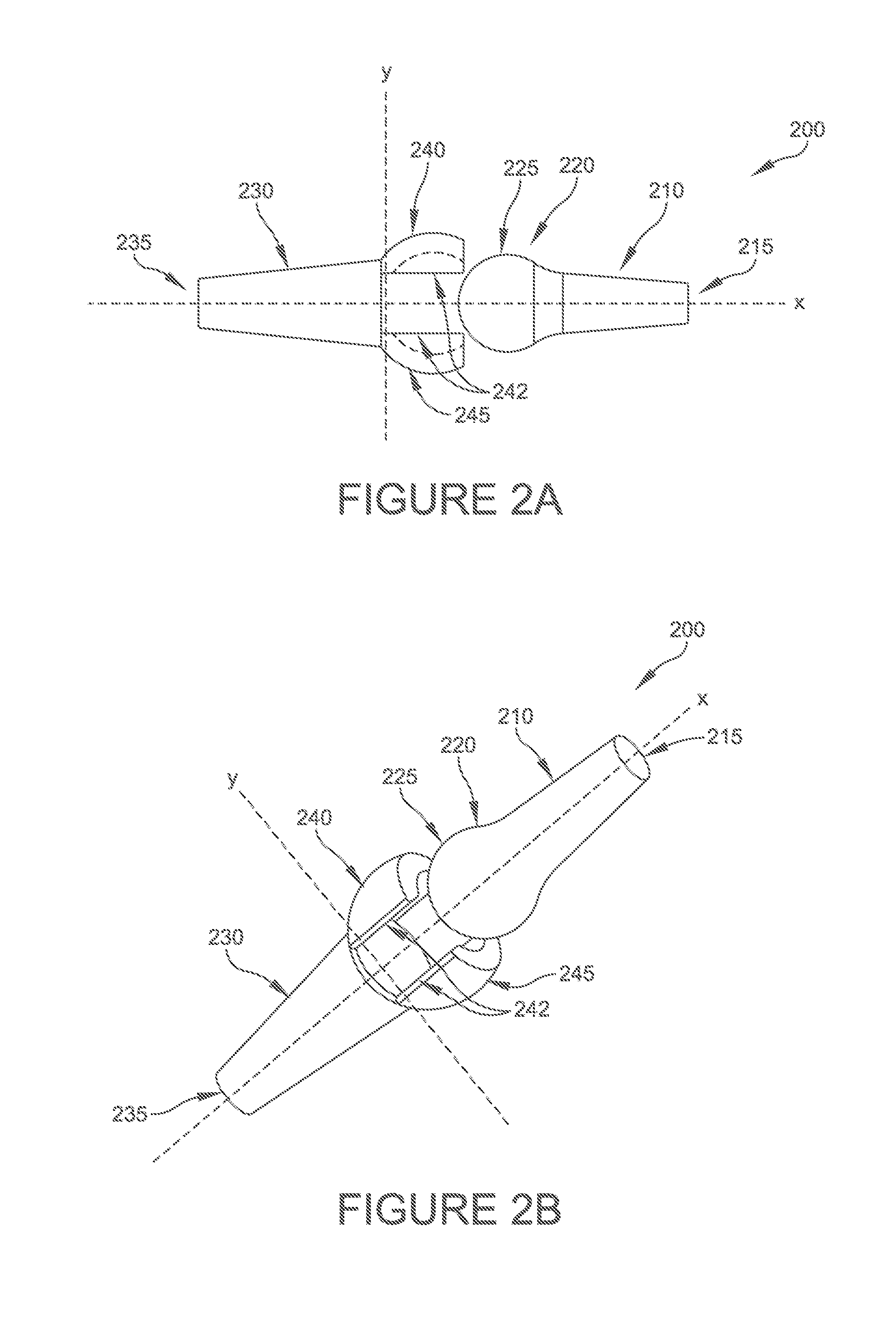
FIG. 2A is a side elevational view of an alternative embodiment of hammertoe implant including a socket portion, having both spherical and cylindrical articulating surfaces;
FIG. 2B is a perspective view of the hammertoe implant shown in FIG. 2A;
FIG. 2C is a side elevational view, partially in phantom, of an assembled hammertoe implant in accordance with FIGS. 2A and 2B;
FIG. 2D is a perspective view of the hammertoe implant shown in FIG. 2C;
FIG. 2E is a side elevational view, partially in phantom, of a hammertoe implant in accordance with FIG. 2A, including with threaded portions;
FIG. 2F is a side elevational view, partially in phantom, of a hammertoe implant in accordance with the embodiment of FIG. 2A, having blade portions;
FIG. 3A is a side elevational, partially exploded, and partially in phantom further embodiment of a hammertoe implant formed in accordance with the invention having spherical and cylindrical articulating surfaces;
FIG. 3B is a perspective view, partially exploded, of the hammertoe implant shown in FIG. 3A;
FIG. 3C is a side elevational view, partially in phantom, of an assembled hammertoe implant in accordance with FIGS. 3A and 3B;
FIG. 3D is a perspective view of the hammertoe implant shown in FIG. 3C;
FIG. 3E is a side elevational view, partially in phantom, of the hammertoe implant shown in FIGS. 3A-3D including threaded portions;
FIG. 3F is a side elevational view, partially in phantom, of the hammertoe implant shown in FIGS. 3A-3D, and including blade portions;
FIG. 4A is an exploded side elevational view, partially in phantom, of a further alternative embodiment of hammertoe implant including a cylindrical articulating surface and corresponding ball portion;
FIG. 4B is a perspective view of the hammertoe implant shown in FIG. 4A;
FIG. 4C is a side elevational view, partially in phantom, of the hammertoe implant shown in FIGS. 4A and 4B;
FIG. 4D is a perspective view of the hammertoe implant shown in FIG. 4C;
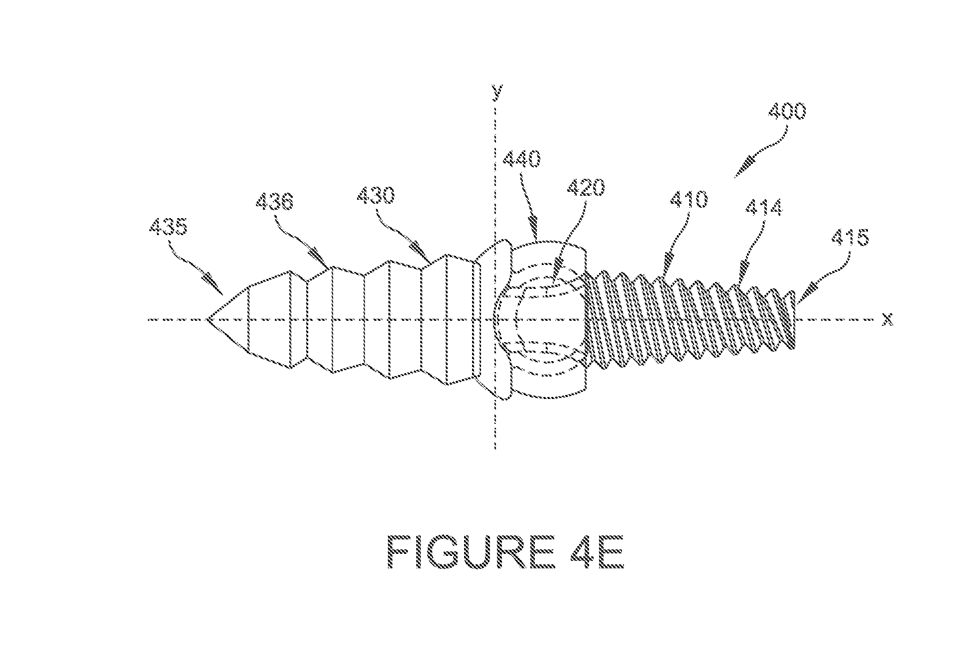
FIG. 4E is a side elevational view, partially in phantom, of a hammertoe implant in accordance with FIG. 4A showing a threaded portion and a blade portion;
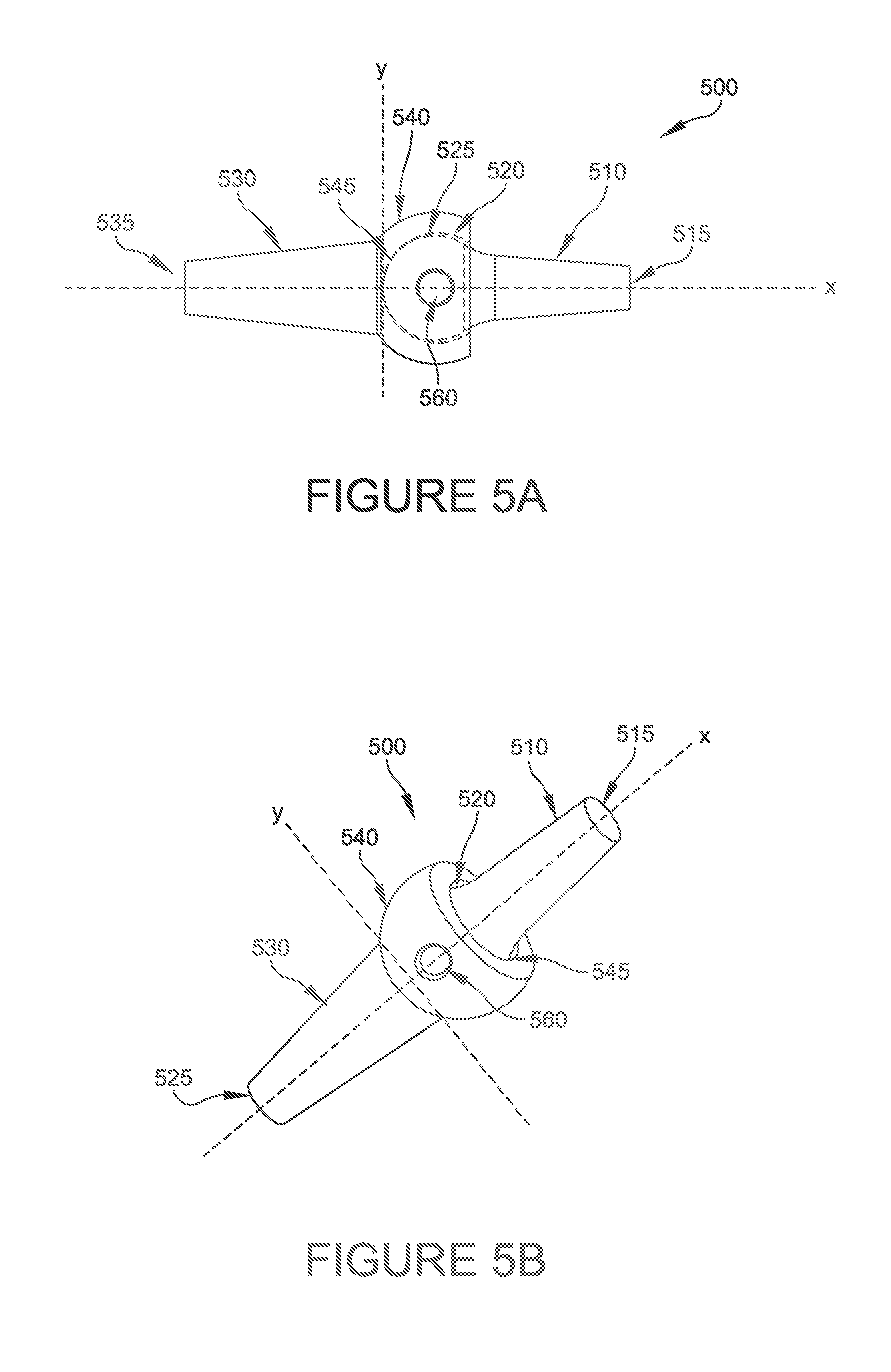
FIG. 5A is a side elevational view, partially in phantom, of a further alternative embodiment of hammertoe implant including a ball portion and a socket portion that together accommodate a cross pin;
FIG. 5B is a perspective view of the hammertoe implant shown in FIG. 5A;
FIG. 5C is a side elevational view, partially in phantom, of the hammertoe implant of FIGS. 5A and 5B including a cross pin shown in phantom;
FIG. 5D is a side elevational view, partially in phantom, of the hammertoe implant shown in FIG. 5C but rotated 90.degree. about axis X;
FIG. 6A is a side elevational view, partially in phantom, of yet a further alternative embodiment of hammertoe implant formed in accordance with the invention showing a flange portion included in a socket portion to limit rotation of a ball portion;
FIG. 6B is a perspective view of a hammertoe implant shown in FIG. 6A;
FIG. 6C is a side elevational view, partially in phantom, of an assembled hammertoe implant in accordance with FIGS. 6A and 6B;
FIG. 6D is a perspective view of the hammertoe implant shown in FIG. 6C;
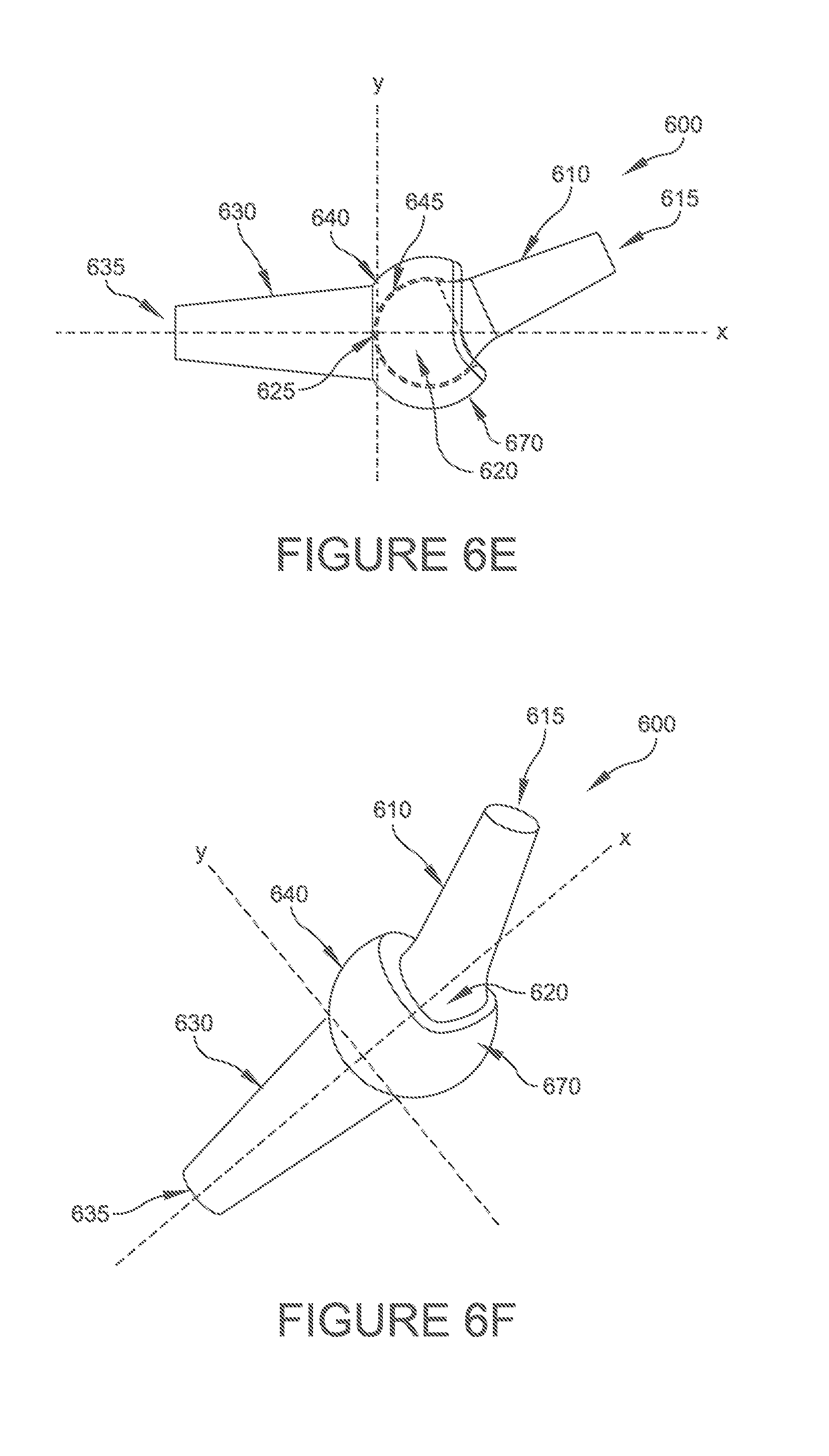
FIG. 6E is a side elevational view, partially in phantom, of the hammertoe implant shown in FIGS. 6A-6D with the ball portion rotated within the socket portion at an angle relative to axes X and Y;
FIG. 6F is a perspective view of the hammertoe implant shown in FIG. 6E;
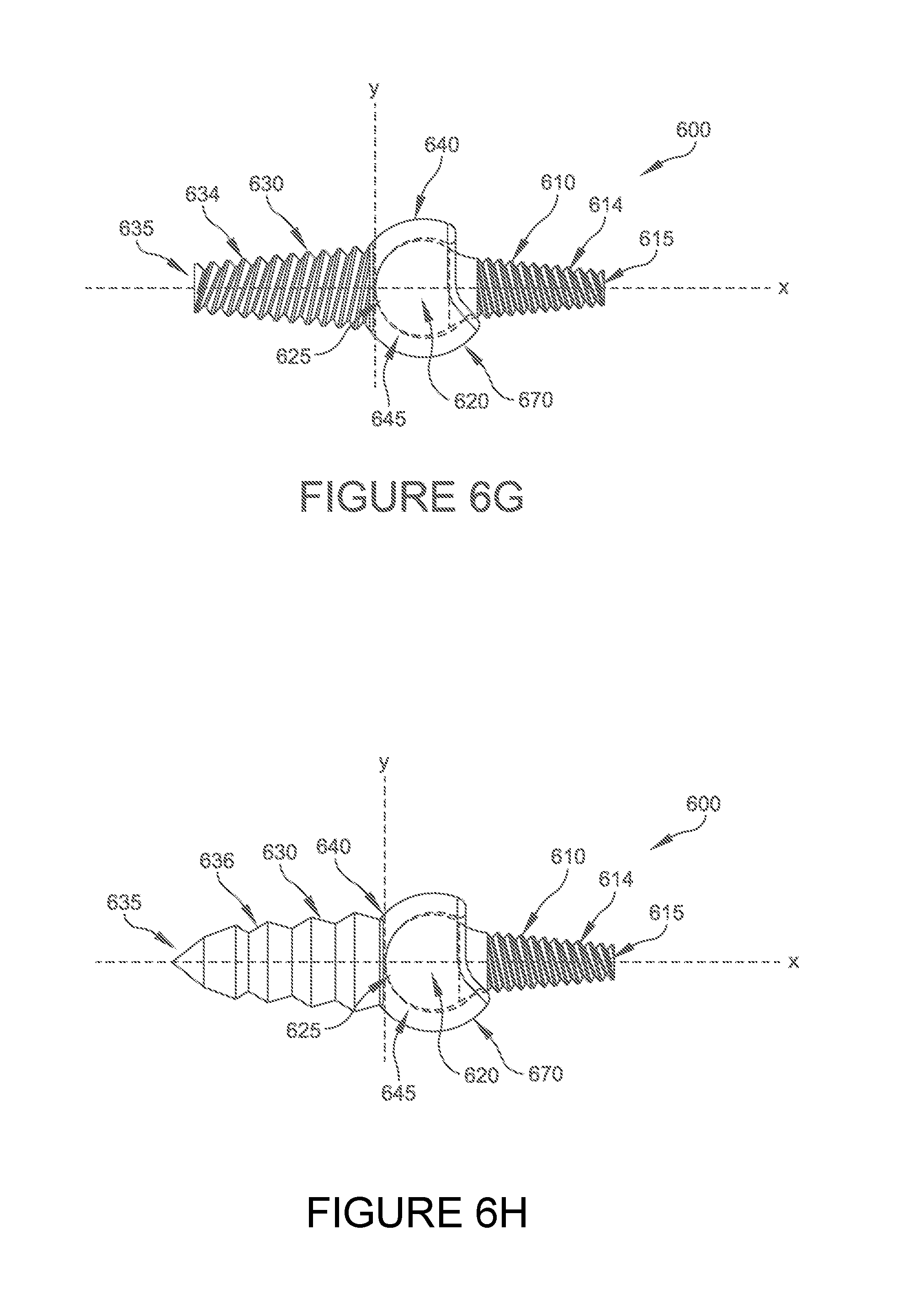
FIG. 6G is a side elevational view, partially in phantom, of a hammertoe implant shown in FIGS. 6A-6F, showing threaded portions;
FIG. 6H is a side elevational view, partially in phantom, of the hammertoe implant of FIGS. 6A-6F but including a threaded portion and a blade portion.
FIG. 7 is a flow chart illustrating a method of correcting a toe bone deformity according to embodiments of the present disclosure.
FIG. 8 is a further flow chart illustrating a method for correcting a bone joint according to one embodiment of the invention.
DETAILED DESCRIPTION
With reference to the Figures, where like elements have been given like numerical designations to facilitate an understanding of the drawings, the various embodiments of cyclic deposition and etch methods are described. The figures are not drawn to scale.
The following description is provided as an enabling teaching of a representative set of examples. Many changes can be made to the embodiments described herein while still obtaining beneficial results. Some of the desired benefits discussed below can be obtained by selecting some of the features or steps discussed herein without utilizing other features or steps. Accordingly, many modifications and adaptations, as well as subsets of the features and steps described herein are possible and can even be desirable in certain circumstances. Thus, the following description is provided as illustrative and is not limiting.
This description of illustrative embodiments is intended to be read in connection with the accompanying drawings, which are to be considered part of the entire written description. In the description of embodiments disclosed herein, any reference to direction or orientation is merely intended for convenience of description and is not intended in any way to limit the scope of the present disclosure. Relative terms such as "lower," "upper," "horizontal," "vertical,", "above," "below," "up," "down," "top" and "bottom" as well as derivative thereof (e.g., "horizontally," "downwardly," "upwardly," etc.) should be construed to refer to the orientation as then described or as shown in the drawing under discussion. Terms such as "longitudinal" and "lateral" are to be interpreted relative to one another or relative to an axis of elongation, or an axis or center of rotation, as appropriate. These relative terms are for convenience of description only and do not require that the apparatus be constructed or operated in a particular orientation. Terms such as "attached," "affixed," "connected" and "interconnected," refer to a relationship wherein structures are secured or attached to one another either directly or indirectly through intervening structures, as well as both movable or rigid attachments or relationships, unless expressly described otherwise. The term "operatively connected" is such an attachment, coupling or connection that allows the pertinent structures to operate as intended by virtue of that relationship. The term "adjacent" as used herein to describe the relationship between structures/components includes both direct contact between the respective structures/components referenced and the presence of other intervening structures/components between respective structures/components. When only a single machine is illustrated, the term "machine" shall also be taken to include any collection of machines that individually or jointly execute a set (or multiple sets) of instructions to perform any one or more of the methodologies discussed herein. In the claims, means-plus-function clauses, if used, are intended to cover the structures described, suggested, or rendered obvious by the written description or drawings for performing the recited function, including not only structural equivalents but also equivalent structures. The terms "implant" and "device" are used interchangeably in this disclosure and such use should not limit the scope of the claims appended herewith.
As used herein, use of a singular article such as "a," "an" and "the" is not intended to exclude pluralities of the article's object unless the context clearly and unambiguously dictates otherwise.
Improved implants for hammer toe and/or claw toe correction are provided. Embodiments of the present subject matter provide a surgeon with a non-rigid construct and fusion of a joint after correction and a period of post-operative healing. Some embodiments can provide a rigid construct for initial post-operative wound healing and soft tissue release/relaxation while permitting predetermined motion back to the joint following a period of initial post-operative healing. Some embodiments can feature a proximal end of an implant including a ball portion and a distal end of the implant including a socket portion. A ball portion can include a portion of the implant having a surface of a suitable shape, including, but not limited to, a spherical, oval, cylindrical, or ellipsoidal shape, and permitting a predetermined movement of the ball portion when operatively connected to the socket portion. The inventors have observed that an implant having a ball portion and a socket portion can provide improved flexibility, stretching and movement at a respective joint post-insertion.
FIG. 1A illustrates a front plan view of a toe bone implant according to some embodiments of the present disclosure. FIG. 1B illustrates a perspective view of a toe bone implant according to some embodiments of the present disclosure. With reference to FIGS. 1A and 1B, an implant 100 for correcting hammertoes can include a first portion 130 and a second portion 110. In the illustrated embodiment, the first portion 130 includes a socket portion 140 disposed at an edge of the first portion 130. The socket portion 140 can be formed of any suitable material. For example, the socket portion 140 can be formed of a polyethylene material. In some embodiments, a socket portion 140 material is selected to permit flexibility in the socket portion 140. In some embodiments, the socket portion 140 can be formed of a first material and the remainder of the first portion 130 can be formed of a second material. For example, the socket portion 140 can be formed of a polyethylene material and the remainder of the first portion 130 can be formed of a second material such as, for example, stainless steel, titanium, or other metals or rigid polymers.
As shown in FIGS. 1A and 1B, the second portion 110 can include a ball portion 120. Ball portion 120 can be formed of any suitable material. For example, ball portion 120 can be formed of a material such as stainless steel, titanium, or other metals or rigid polymers. In some embodiments, the second portion 110, including ball portion 120, can be formed of the same material. In other embodiments, the ball portion 120 can be formed of a first material and the remainder of the second portion 110 can be formed of a second material. In the illustrated embodiment, socket portion 140 can be configured to receive ball portion 120. In some embodiments, socket portion 140 and ball portion 120 include respective articulating surfaces 145, 125 such that ball portion 120 is configured to move a predetermined amount respective to the socket portion 140 when operatively connected to the socket portion 140. For example, socket portion 140 and ball portion 120 can include respective articulating surfaces 145, 125 such that ball portion 120 is configured to rotate a predetermined amount about an axis of rotation respective to the socket portion 140 when operatively connected to the socket portion 140. Ball portion 120 and socket portion 140 can be formed of any suitable shape. For example, a ball portion 120 can include an articulating surface 125 of a suitable shape, including, but not limited to, a spherical, oval, cylindrical, or ellipsoidal shape, and permitting a predetermined movement of the ball portion 120 when operatively connected to the socket portion 140. Socket portion 140 can include an articulating surface 145 of a suitable shape such as, for example, a spherical, oval, cylindrical, or ellipsoidal shape, such that ball portion 120 is configured to move a predetermined amount respective to the socket portion 140 when operatively connected to the socket portion 140.
FIGS. 1A and 1B illustrate a toe bone implant 100 prior to operatively connecting the ball portion 120 and the socket portion 140. In the illustrated embodiment, toe bone implant 100 is shown prior to insertion into a joint. Toe bone implant 100 can include an edge portion 135 of first portion 130 and an edge portion 115 of second portion 110. As shown, respective edge portions 135, 115 are on opposing edges of the socket portion 140 of first portion 130 and ball portion 120 of second portion 110. In some embodiments (not shown), implant 100 can include a resorbable portion operatively connected to the first 130 and second 110 portions and configured to limit the rotation of the ball portion 120 respective to the socket portion 140 for a predetermined period of time. Any suitable resorbable device can be used. For example, a resorbable pin, bridge, or lock out device can be used to limit the rotation of the ball portion 120 respective to the socket portion 140 for a predetermined period of time. Any suitable resorbable material can be used to form the resorbable portion. For example, a bioresorbable material including, but not limited to, polylactide (PLA), poly-L-lactide (PLLA), polyglycolide (PGA), co-polymers of PLA and PGA including PGLA, poly-DL-lactide (PDLLA), co-polymers thereof, or other suitable bioabsorble polymers, biopolymers or biodegradable polymers can be used to form the resorbable portion. In some embodiments, a resorbable snap on, lock out device can be used to hold the implant 100 in a predetermined initial position for a predetermined period of time. In some embodiments, a resorbable bridge that could cross a joint where the implant was inserted can be used to hold the implant 100 in a predetermined initial position for a predetermined period of time. In some embodiments, the predetermined period of time is an initial healing period. For example, an initial healing period could be approximately six weeks (e.g. 5-7 weeks). In some embodiments the predetermined period of time can be a period between approximately 8-12 weeks (e.g. 7-13 weeks). However, any suitable predetermined period of time can be used. The inventors have observed that an implant having rigid fixation for a predetermined period of time achieved through the use of a resorbable device, and after resorption, permitting a predetermined amount of rotation of a ball portion 120 of the implant 100 relative to the socket portion 140, can provide significant improvements to patients suffering from hammertoe or claw toe.
Referring now to FIGS. 1C and 1D, a front plan view and a perspective view of a toe bone implant 100 are respectively provided after operatively connecting the ball portion 120 and the socket portion 140. In the illustrated embodiment, toe bone implant 100 is shown prior to insertion into a joint. In some embodiments, ball portion 120 can be configured to rotate a predetermined amount respective to socket portion 140 in a lateral direction (x). In some embodiments, ball portion 120 can be configured to rotate a predetermined amount respective to socket portion 140 about a lateral axis (x). In some embodiments, rotation in lateral direction (x) can be referred to as rotation in a plantar direction, e.g. toward the sole, i.e. at a substantially 90 degree angle between the front part of the foot and the shin. In some embodiments, ball portion 120 can be configured to rotate a predetermined amount respective to socket portion 140 in a longitudinal direction (y). In some embodiments, ball portion 120 can be configured to rotate a predetermined amount respective to socket portion 140 about a longitudinal axis (y). In some embodiments, rotation in longitudinal direction (y) can be referred to as rotation in a dorsal direction, e.g. toward or away from a shin bone. In some embodiments, ball portion 120 can be configured to rotate a predetermined amount respective to socket portion 140 in a longitudinal direction (y) and a lateral direction (x). In some embodiments, ball portion 120 can be configured to rotate a predetermined amount respective to socket portion 140 about a longitudinal axis (y) and a lateral axis (x). In the illustrated embodiment, ball portion 120 is configured to freely rotate respective to socket portion 140.
With reference to FIG. 1E, a front plan view of a toe bone implant 100 according to some embodiments is provided. As shown in FIG. 1E, a portion of first portion 130 and a portion of second portion 110 can be threaded 134, 114. The threads 134, 114 may be threaded in substantially the same direction or in opposing directions. As ball portion 120 is configured to freely rotate respective to socket portion 140, both the respective first 130 and second 110 portions can be threaded into a respective bone canal. As shown, the threaded portion 134, 114 of first 130 and second 110 portions can include a plurality of threads disposed along its respective length. The tip (not shown) of respective threaded portions 134, 114 can be pointed to facilitate the advancement of threads 134, 114 into a respective bone. The respective edge portions 135, 115 can have any suitable type of interfacing mechanism to accept a suitable implant drivers such as a screw head or the like. In some embodiments, the respective edge portions 135, 115 can include a female depression (not shown) adaptable to mate with a driver (not shown) having a male extension. In some embodiments, for example, the respective edge portions 135, 115 1 can have a portion in the shape of a hex whereby a suitable driver has a corresponding hex adapter appropriate to drive the implant 100 into a respective bone.
Referring now to FIG. 1F, a front plan view of an implant 100 is shown according to some embodiments of the present disclosure. In the illustrated embodiment, a portion of first portion 130 includes blades 136 to improve alignment or implantation while inserting the first portion 130 into a bone canal. As shown, blade portion 136 includes a plurality of serrated edges on its top and bottom sides. In some embodiments, blade portion 136 can have a width that is greater than its thickness and can taper to a point. In some embodiments such as embodiments using a resorbable pin, a portion of first portion 130 can include blades 136 to improve alignment or implantation while inserting the first portion 130 into a bone canal. In some embodiments (not shown), a portion of first portion 130 can include barbs 136 to improve alignment or implantation while inserting the first portion 130 into a bone canal.
In various embodiments, an implant 100 can be implanted into targeted bones by any suitable method. For example, an implant 100 can be implanted or installed via a retrograde approach between, for example, proximate and middle phalanxes in a foot. One skilled in the art will understand that the method described herein may be applied to the middle and distal phalanxes, respective metatarsals, as well or other adjacent bones. In some embodiments, an implant 100 can be implanted via a retrograde approach between, for example, a phalanx and a metatarsal in a foot. In some embodiments, a driver can be used to implant an implant 100 into a joint. For example, a driver can be an elongated instrument and include one end having an adaptable portion suitable for mating with an implant 100 described above. In some embodiments, the adaptable portion can include a male hexagonal head adaptable to mate to a corresponding female depression in an edge portion 135, 115 of an implant 100. In some embodiments, an opposing end of the driver can include a driving pin or trocar and can include a flat modular section configured to accept a handle or other suitable mechanism to assist a surgeon during installation of an implant 100.
Referring now to FIG. 7, a flow chart showing a method of correcting a toe bone deformity is provided. At block 710, a joint is exposed between first and second bones. In some embodiments, the joint is a proximal interphalangeal (PIP) joint. In some embodiments, the joint is a distal interphalangeal (DIP) joint. In some embodiments, the joint is a metatarsal phalangeal joint. In some embodiments, a toe can be opened to provide access to a joint between a first bone and a second bone. For example, a toe can be opened to provide access to a joint between a middle phalanx and a proximal phalanx, or, for example, between a distal phalanx and a proximal metatarsal. In some embodiments, an incision is made to open the joint. In some embodiments, the first and/or second bones, respectively, may be resected using a bone saw or other tool, if necessary. The resected surfaces of the first and/or second bones can be debrided if necessary. At block 720, bone implant 100 can be inserted into the joint. Any suitable insertion method can be used. At block 730, an edge portion 135, 115 of respective first 130 and second 110 implant portions is inserted into respective first and second bones. Any suitable method to insert the respective edge portions 115, 135 into first and second bones. For example, an intermedullary canal can be drilled into one or both of the first and second bones using a drill or other mechanism to an appropriate depth. In some embodiments, a reamer can be used for precise and accurate canal drilling. In some embodiments, a driver can be engaged with an edge portion 135 of the first portion 130 of an implant 100 as described above, and an edge portion 115 of the second portion 110 of the implant 100 can be threaded into the first bone. In some embodiments, bladed portion 136 of first portion 130 can be disposed within a slot of a driving adapter and the body of the driving adapter can be secured in a chuck of a drill or other driving instrument. A drill or other driving instrument can be used to drive threaded portion 114 of second portion 110 into a surface of a second bone, for example, a proximal metatarsal. With the threaded portion 114 of second portion 110 of implant 100 disposed within second bone, a driving adapter can be disengaged from blade portion 136 of first portion 130 of implant 100.
The first bone, for example a distal phalanx, can be predrilled or broached using a drill, or other suitable device, to create a hole. In some embodiments, a reamer can be used for precise drilling or broaching. The predrilled or broached first bone is then repositioned such that the predrilled hole or broach aligns with the blade portion 136 of first portion 130 of implant 100. The first bone is then pressed into engagement with the blade portion 136 of first portion 130. The serrated edges of blade portion 136 of first portion 130 help to maintain engagement between first bone and blade portion 136 of first portion 130 of implant 100. In some embodiments, a ball portion 120 of second portion 110 can be operatively connected to a socket portion 140 of first portion 130 in situ. In some embodiments, a ball portion 120 of second portion 110 can be operatively connected to a socket portion 140 of first portion 130 prior to insertion of toe implant 100 into the joint. At block 740, the ball portion 120 is aligned with socket portion 140 such that ball portion 120 is configured to rotate a predetermined amount relative to socket portion 140. In some embodiments (e.g. FIGS. 2, 3, 4, 6), a ball portion of a second portion can be operatively connected to a socket portion of a first portion in situ. In some embodiments, the respective edge portions of ball portion 120 of second portion 110 and socket portion 140 of first portion 130 are inserted into respective first and second bones such that the ball portion 120 is aligned with socket portion 140 and is configured to rotate a predetermined amount relative to the socket portion 140.
With reference now to FIGS. 2A-2F, various plan and perspective views of an implant 200 according to some embodiments of the present disclosures are provided. In the illustrated embodiment, the first portion 230 and second portion 210 can be inserted (720) into a joint independent of each other. The ball portion 220 can be operatively connected to the socket portion 240 in situ. As shown and described above, socket portion 240 is formed of a material flexible enough to allow insertion and operative connection of the ball portion 220 of second portion 210. In some embodiments, the force required to insert ball portion 220 into socket portion 240 is less than the force required to remove ball portion 220 from socket portion 240. As shown in FIGS. 2B-2F, ball portion 220 will not detach from socket portion 240. With reference now to FIGS. 2B and 2D, both spherical 225, 245 and cylindrical 242 articulating surfaces can be provided on the ball portion 220 and socket portion 240 to limit the rotation of the ball portion 220 relative to the socket portion 240 to dorsi/plantar flexion. In some embodiments, where the predetermined amount of rotation of the ball portion 220 relative to socket portion 240 is limited to dorsiflexion, a greater amount of material can be added to the plantar portion of socket portion 240 of the first portion 230 of implant 200.
In some embodiments, an open procedure can be used to expose a joint (710), for inserting the implant 200 into the joint, and for soft tissue release. As discussed above, first and second bones can be resected in some embodiments. In some embodiments, a reamer can be used to for accurate and precise drilling of a canal into respective first and second bones. As shown in FIG. 2E, first 230 and second 210 portions can include respective threaded portions 234, 214. In some embodiments, respective edge portions 235, 215 can be threaded into canals as described above (715) as the first 230 and second 210 portions are implanted independently and operatively connected in situ. As shown in FIG. 2F, first 230 and second 210 portions can include respective bladed portion 236, 216. In some embodiments, respective edge portions 235, 215 can be inserted into respective first and second bones independently and ball portion 220 inserted into and operatively connected to socket portion 240 in situ to align ball portion 220 with socket portion 240 and configure it to rotate a predetermined amount relative to socket portion 240. In some embodiments (not shown), implant 200 can include a resorbable portion operatively connected to the first 230 and second 210 portions and configured to limit the rotation of the ball portion 220 respective to the socket portion 240 for a predetermined period of time as described above.
Referring now to FIGS. 3A-3F, various plan and perspective views of implant 300 are provided according to some embodiments of the present disclosure. As shown in FIGS. 3B and 3D, both spherical 325, 345 and cylindrical 342 articulating surfaces can be provided on the ball portion 320 and socket portion 340 to limit the rotation of the ball portion 320 relative to the socket portion 340 to dorsi/plantar flexion. In some embodiments, where the predetermined amount of rotation of the ball portion 320 relative to socket portion 340 is limited to dorsiflexion, a greater amount of material can be added to the plantar portion of socket portion 340 of the first portion 330 of implant 300. As shown in the illustrated embodiments of 2B, 2D, 3B and 3D, there is less dorsal/plantar constraint in the embodiments illustrated in FIGS. 3B and 3D and more dorsal/plantar constraint in the embodiments shown in FIGS. 2B and 2D.
In some embodiments, an open procedure can be used to expose a joint (710), for inserting the implant 300 into the joint, and for soft tissue release. As discussed above, first and second bones can be resected in some embodiments. In some embodiments, a reamer can be used to for accurate and precise drilling of a canal into respective first and second bones. As shown in FIG. 3E, first 330 and second 310 portions can include respective threaded portions 334, 314. In some embodiments, respective edge portions 335, 315 can be threaded into canals as described above (715) as the first 330 and second 310 portions are implanted independently and operatively connected in situ. As shown in FIG. 2F, first 330 and second 310 portions can include respective bladed portion 336, 316. In some embodiments, respective edge portions 335, 315 can be inserted into respective first and second bones independently and ball portion 320 inserted into and operatively connected to socket portion 340 in situ to align ball portion 320 with socket portion 340 and configure it to rotate a predetermined amount relative to socket portion 340. In some embodiments (not shown), implant 300 can include a resorbable portion operatively connected to the first 330 and second 310 portions and configured to limit the rotation of the ball portion 320 respective to the socket portion 340 for a predetermined period of time as described above.
Referring now to FIGS. 4A-4E, various plan and perspective views of an implant 400 are provided according to some embodiments of the present disclosure. As illustrated in FIGS. 4A and 4C, ball portion 420 and socket portion 440 can include respective cylindrical articulating surfaces 427, 447 and respective spherical articulating surfaces 445, 425 to limit the rotation of the ball portion 420 relative to the socket portion 440 to a predetermined amount. In the illustrated embodiment, interior portion 450 formed in socket portion 440 along with respective cylindrical articulating surfaces 427, 447 and respective spherical articulating surfaces 445, 425 creates a hinge type of implant 400 and limits rotation of the ball portion 420 relative to socket portion 440 to dorsal/plantar flexion. In some embodiments, where the predetermined amount of rotation of the ball portion 420 relative to socket portion 440 is limited to dorsiflexion, a greater amount of material can be added to the plantar portion of socket portion 440 of the first portion 430 of implant 400.
In some embodiments, an open procedure can be used to expose a joint (710), for inserting the implant 400 into the joint, and for soft tissue release. As discussed above, first and second bones can be resected in some embodiments. In some embodiments, a reamer can be used to for accurate and precise drilling of a canal into respective first and second bones. In some embodiments (not shown), first 430 and second 410 portions can include respective threaded portions (not shown). In some embodiments (not shown), respective edge portions 435, 415 can be threaded into canals as described above (715) as the first 430 and second 410 portions are implanted independently and operatively connected in situ. As shown in FIG. 4E, in some embodiments, first portion 430 can include a bladed portion 436 and second portion 410 can include a threaded portion 414 and respective edge portions 435, 415 can be threaded into canals as described above (715) as the first 430 and second 410 portions are implanted independently and operatively connected in situ. In some embodiments (not shown), first 430 and second 310 portions can include respective bladed portions. In some embodiments (not shown), first 430 and second 310 portions can include respective barbed portions. In some embodiments, respective edge portions 435, 415 can be inserted into respective first and second bones independently and ball portion 420 inserted into and operatively connected to socket portion 440 in situ to align ball portion 420 with socket portion 440 and configure it to rotate a predetermined amount relative to socket portion 440. In some embodiments (not shown), implant 400 can include a resorbable portion operatively connected to the first 430 and second 410 portions and configured to limit the rotation of the ball portion 420 respective to the socket portion 440 for a predetermined period of time as described above.
Referring now to FIGS. 5A-5D, various plan and perspective views of a hinge type bone implant 500 according to some embodiments of the present disclosure are provided. In the illustrated embodiments, the ball portion 520 is inserted into the socket portion 540 prior to inserting the bone implant 500 into a joint (720). As shown in the illustrated embodiment, a cross pin 560 can be inserted between the ball portion 520 and the socket portion 540 to limit rotation of the ball portion 520 relative to the socket portion 540 to dorsi/plantar flexion. In some embodiments, the ball portion 520 can be disposed asymmetrically relative to the socket portion 540 to further limit rotation to a predetermined amount. In some embodiments, and as shown in FIG. 5C, resorbable cross-pin ends 565 can be included to restrict rotation of the ball portion 520 relative to the socket portion 520 for a predetermined period of time as described above. In some embodiments, where the predetermined amount of rotation of the ball portion 520 relative to socket portion 540 is limited to dorsiflexion, a greater amount of material can be added to the plantar portion of socket portion 540 of the first portion 530 of implant 500.
In some embodiments, an open procedure can be used to expose a joint (710), for inserting the implant 500 into the joint, and for soft tissue release. As discussed above, first and second bones can be resected in some embodiments. In some embodiments, a reamer can be used to for accurate and precise drilling of a canal into respective first and second bones. In some embodiments (not shown), one of the first 530 or second 510 portions can include a respective threaded portions (not shown) as the implant 500 is assembled prior to insertion into a joint. In some embodiments (not shown), the respective edge portion 435 (or 415) of the respective portion including a threaded portion can be threaded into a respective canal as described above (715). In some embodiments, the other one of the first 530 or second 510 portions of the implant 500 can include a bladed portion. In some embodiments, the other one of the first 530 or second 510 portions of the implant 500 can include a barbed portion.
With reference now to FIGS. 6A-6H, various plan and perspective views of an implant 600 according to some embodiments of the present disclosure are provided. In the illustrated embodiments, a flange portion 670 is included in socket portion 640 to limit the rotation of the ball portion 620 relative to socket portion 640 in the plantar flexion direction. As shown in FIGS. 6E and 6F, ball portion 620 can be disposed asymmetrically relative to socket portion 640 to further limit the rotation of the ball portion 620 relative to socket portion 640 in the plantar flexion direction. As shown in the illustrated embodiment, ball portion 620 and socket portion 640 include respective spherical articulating surfaces which provide rotation of the ball portion 620 a predetermined amount relative to the socket portion 640.
As shown in FIG. 6G, in embodiments where the implant 600 is assembled in situ, first portion 630 and second portion 610 can include respective threaded portion 634, 614. In embodiments where the implant 600 in assembled prior to insertion into the joint (at block 720), one of the first 630 or second 610 portions can include a respective threaded portion (e.g. FIG. 6H and threaded portion 614) and the other one of the first 630 or second 610 portions of the implant 600 can include a bladed portion (e.g. FIG. 6H and threaded portion 616). In some embodiments, the other one of the first 630 or second 610 portions of the implant 600 can include a barbed portion (not shown). In some embodiments (not shown), implant 600 can include a resorbable portion operatively connected to the first 630 and second 610 portions and configured to limit the rotation of the ball portion 620 respective to the socket portion 640 for a predetermined period of time as described above. In embodiments having a resorbable portion, a barbed or bladed portion can be included on the portion of the implant 600 configured for insertion into the distal bone for improved alignment and implantation.
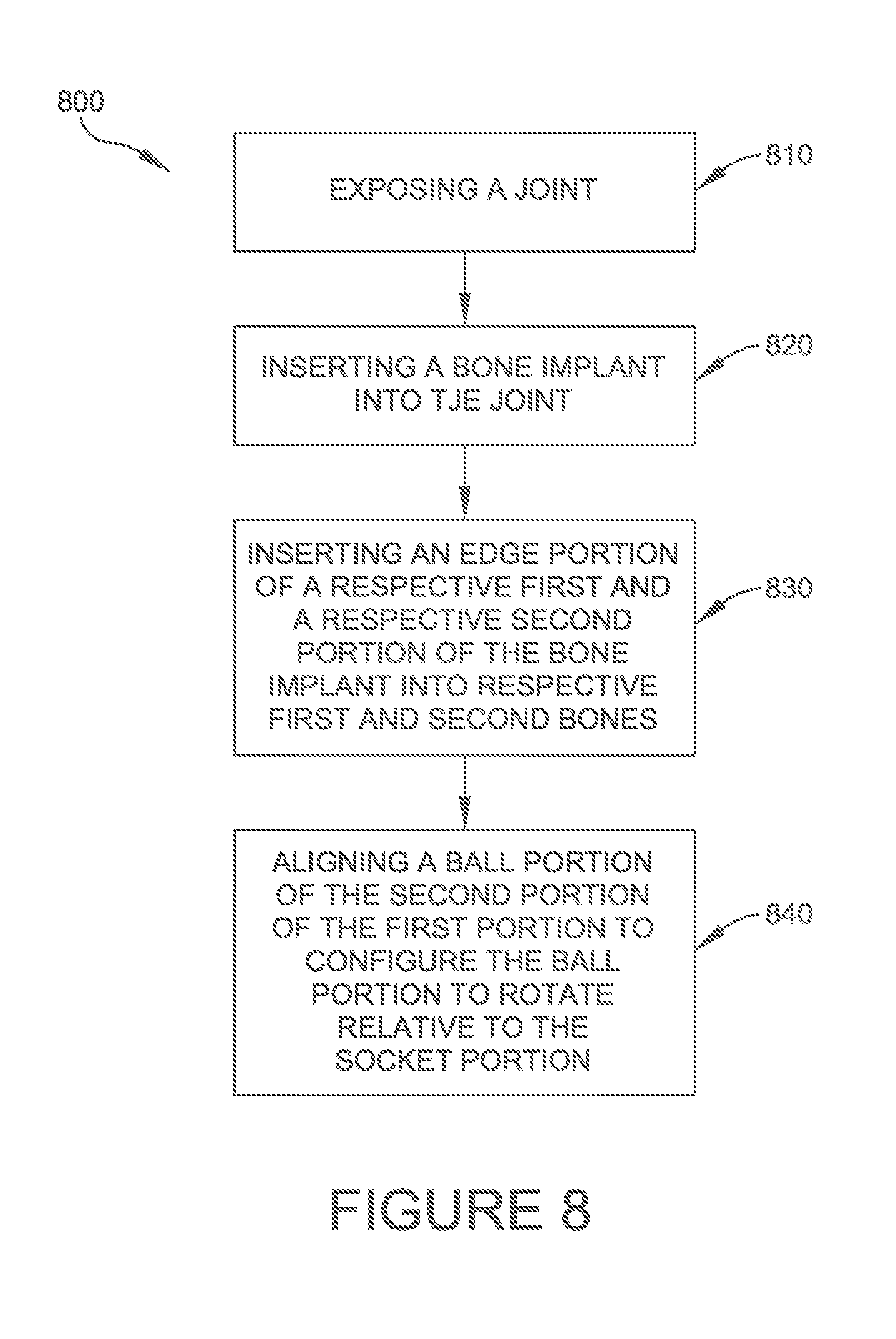
Referring now to FIG. 8, a flow chart showing a method of correcting a toe bone deformity is provided. At block 810, a joint is exposed between first and second bones as described above for block 710. In some embodiments, the joint is a proximal interphalangeal (PIP) joint. In some embodiments, the joint is a distal interphalangeal (DIP) joint. In some embodiments, the joint is a metatarsal phalangeal joint. At block 820, bone implant 100 (200, 300, 400, 500, 600) can be inserted into the joint as described above for block 720. At block 830, an edge portion of the respective first 130 (230, 330, 430, 530, 630) and second 110 (210, 310, 410, 510, 610) portions is inserted into the respective first and second bones as described above for block 730. At block 840, a ball portion 120 (220, 320, 420, 520, 620) of the second portion 110 (210, 310, 410, 510, 610) can be aligned with a socket portion 140 (240, 340, 440, 540, 640) of the first portion 130 (230, 330, 430, 530, 630) such that the ball portion 120 (220, 320, 420, 520, 620) is configured to rotate a predetermined amount relative to the socket portion 140 (240, 340, 440, 540, 640) In some embodiments, a ball portion 220 (320, 420, 620) of second portion 210 (310, 410, 610) can be operatively connected to a socket portion 240 (340, 440, 640) of first portion 230 (330, 430, 630) in situ. In some embodiments, a ball portion 120 (520, 620) of second portion 110 (510, 610) can be operatively connected to a socket portion 140 (540, 640) of first portion 130 (530, 630) prior to inserting the bone implant 100 (500, 600) into a joint (820). In some embodiments, the respective edge portions of ball portion 120 (220, 320, 420, 520, 620) of second portion 110 (210, 310, 410, 510, 610) and socket portion 140 (240, 340, 440, 540, 640) of first portion 130 (230, 330, 430, 530, 630) are inserted into respective first and second bones such that the ball portion 120 (220, 320, 420, 520, 620) is aligned with socket portion 140 (240, 340, 440, 540, 640) and is configured to rotate a predetermined amount relative to the socket portion 140 (240, 340, 440, 540, 640).
Although reference has been made to a patient's proximal and distal interphalangeal joints and metatarsal phalangeal joints, one skilled in the art will understand that embodiments of the present disclosure may be implemented for other respective bones including, but not limited to other phalanges/digits and phalangeal/digital joints.
It may be emphasized that the above-described and illustrated embodiments are merely possible examples of implementations and merely set forth for a clear understanding of the principles of the disclosure. Many variations and modifications may be made to the above-described embodiments of the disclosure without departing substantially from the spirit and principles of the disclosure. All such modifications and variations are intended to be included herein within the scope of this disclosure and the present disclosure and protected by the following claims.
While this specification contains many specifics, these should not be construed as limitations on the scope of the claimed subject matter, but rather as descriptions of features that may be specific to particular embodiments. Certain features that are described in this specification in the context of separate embodiments can also be implemented in combination in a single embodiment. Conversely, various features that are described in the context of a single embodiment can also be implemented in multiple embodiments separately or in any suitable sub-combination. Moreover, although features may be described above as acting in certain combinations and even initially claimed as such, one or more features from a claimed combination can in some cases be excised from the combination, and the claimed combination may be directed to a sub-combination or variation of a sub-combination.
As shown by the various configurations and embodiments illustrated in FIGS. 1A-8, improved toe bone implants and methods of correcting toe bone deformities have been described.
Some embodiments provide a toe bone implant. The toe bone implant includes a first portion having a socket portion. The toe bone implant also includes a second portion having a ball portion operatively connected to the socket portion. The toe bone implant is implanted in a joint such that the ball portion is configured to rotate a predetermined amount respective to the socket portion.
Some embodiments provide a method of correcting a toe bone deformity. The method includes exposing a joint between first and second bones and inserting a bone implant into the joint. The bone implant includes a first portion including a socket portion and a second portion including a ball portion operatively connected to the socket portion. The method includes inserting an edge portion of the respective first and second portions into the respective first and second bones, and aligning the ball portion with the socket portion such that the ball portion is configured to rotate a predetermined amount relative to the socket portion.
Some embodiments provide a toe bone implant. The toe bone implant includes a first portion having a socket portion. The toe bone implant includes a second portion having a ball portion operatively connected to the socket portion such that the ball portion is configured to rotate a predetermined amount respective to the socket portion. The toe bone implant also includes a resorbable portion operatively connected to the first and second portions and configured to limit rotation of the ball portion respective to the socket portion for a predetermined period of time.
While various embodiments are described herein, it is to be understood that the embodiments described are illustrative only and that the scope of the subject matter is to be accorded a full range of equivalents, many variations and modifications naturally occurring to those of skill in the art from a perusal hereof.
* * * * *
D00000
D00001
D00002
D00003
D00004
D00005
D00006
D00007
D00008
D00009
D00010
D00011
D00012
D00013
D00014

D00015

D00016

D00017
D00018
D00019

D00020
XML
uspto.report is an independent third-party trademark research tool that is not affiliated, endorsed, or sponsored by the United States Patent and Trademark Office (USPTO) or any other governmental organization. The information provided by uspto.report is based on publicly available data at the time of writing and is intended for informational purposes only.
While we strive to provide accurate and up-to-date information, we do not guarantee the accuracy, completeness, reliability, or suitability of the information displayed on this site. The use of this site is at your own risk. Any reliance you place on such information is therefore strictly at your own risk.
All official trademark data, including owner information, should be verified by visiting the official USPTO website at www.uspto.gov. This site is not intended to replace professional legal advice and should not be used as a substitute for consulting with a legal professional who is knowledgeable about trademark law.