Detecting blockage of a reservoir cavity during a seating operation of a fluid infusion device
Alderete, Jr. , et al.
U.S. patent number 10,275,572 [Application Number 14/267,696] was granted by the patent office on 2019-04-30 for detecting blockage of a reservoir cavity during a seating operation of a fluid infusion device. This patent grant is currently assigned to MEDTRONIC MINIMED, INC.. The grantee listed for this patent is MEDTRONIC MINIMED, INC.. Invention is credited to Juan M. Alderete, Jr., Alexander S. Campbell, Steve Chow, Hsiao-Yu S. Kow, Salman Monirabbasi, Dmytro Y. Sokolovskyy, Andrew E. Weaver.


View All Diagrams
| United States Patent | 10,275,572 |
| Alderete, Jr. , et al. | April 30, 2019 |
Detecting blockage of a reservoir cavity during a seating operation of a fluid infusion device
Abstract
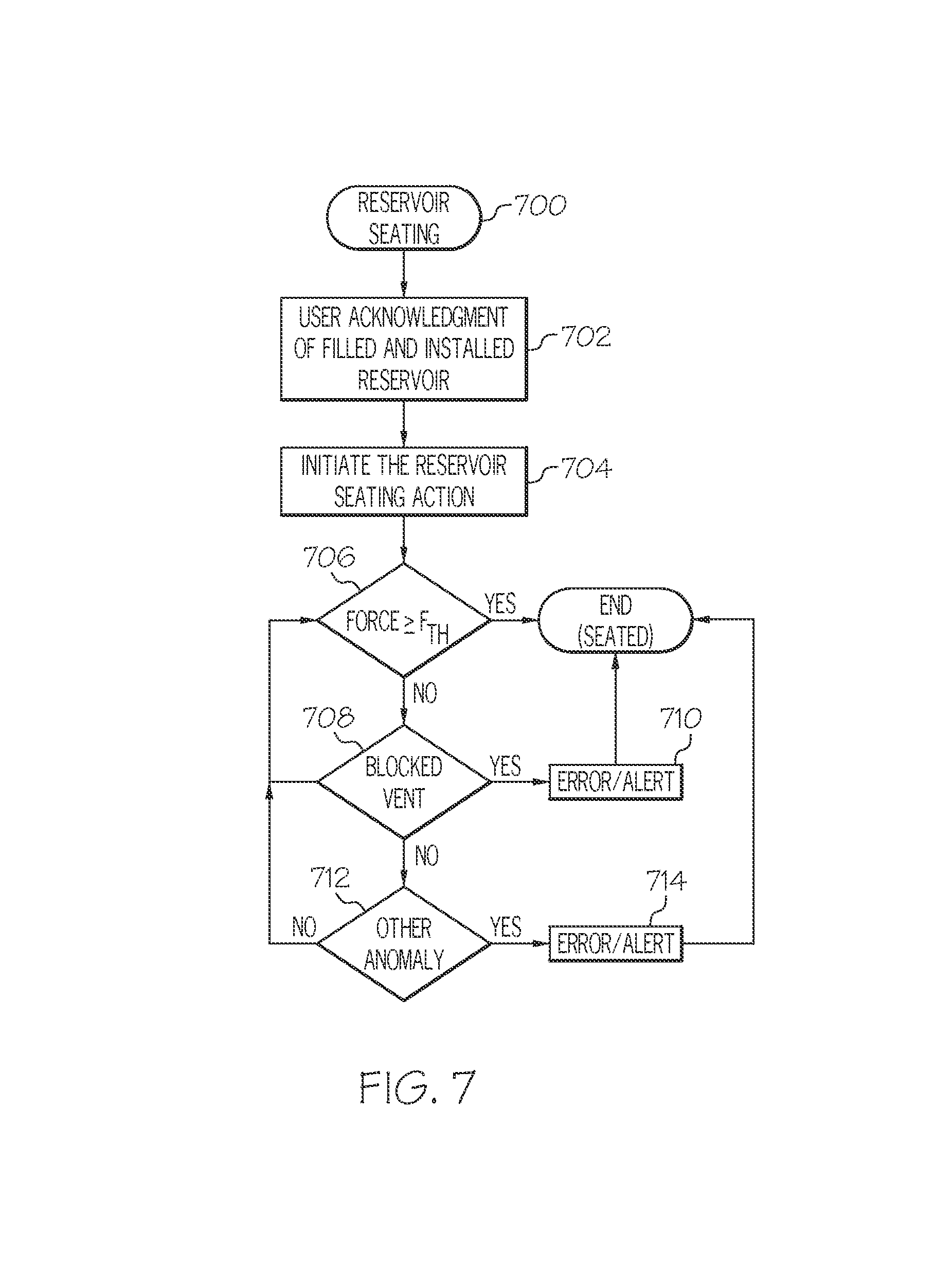
A fluid infusion device and related operating methods are presented here. An exemplary embodiment of the device includes a drive motor assembly, a force sensor associated with the drive motor assembly, and a reservoir cavity that accommodates fluid reservoirs. An exemplary operating method for the device obtains force measurements for a reservoir seating action of the drive motor assembly, where the force measurements indicate measures of force imparted to the force sensor during the reservoir seating action. The method continues by determining that a vent in the reservoir cavity is blocked, based on an analysis of the force measurements, and by initiating corrective action for the fluid infusion device in response to determining that the vent in the reservoir cavity is blocked.
| Inventors: | Alderete, Jr.; Juan M. (Granada Hills, CA), Campbell; Alexander S. (Tarzana, CA), Chow; Steve (Northridge, CA), Kow; Hsiao-Yu S. (Ladera Ranch, CA), Monirabbasi; Salman (Playa Vista, CA), Sokolovskyy; Dmytro Y. (Simi Valley, CA), Weaver; Andrew E. (Granada Hills, CA) | ||||||||||
|---|---|---|---|---|---|---|---|---|---|---|---|
| Applicant: |
|
||||||||||
| Assignee: | MEDTRONIC MINIMED, INC.
(Northridge, CA) |
||||||||||
| Family ID: | 54354415 | ||||||||||
| Appl. No.: | 14/267,696 | ||||||||||
| Filed: | May 1, 2014 |
Prior Publication Data
| Document Identifier | Publication Date | |
|---|---|---|
| US 20150314068 A1 | Nov 5, 2015 | |
| Current U.S. Class: | 1/1 |
| Current CPC Class: | A61M 5/14244 (20130101); G06F 19/3468 (20130101); G16H 20/17 (20180101); G16H 40/63 (20180101); A61M 5/14216 (20130101); A61M 5/1452 (20130101); A61M 2205/332 (20130101) |
| Current International Class: | A61M 5/172 (20060101); G16H 40/63 (20180101); A61M 5/142 (20060101); A61M 5/145 (20060101) |
References Cited [Referenced By]
U.S. Patent Documents
| 3631847 | January 1972 | Hobbs, II |
| 4212738 | July 1980 | Henne |
| 4270532 | June 1981 | Franetzki et al. |
| 4282872 | August 1981 | Franetzki et al. |
| 4373527 | February 1983 | Fischell |
| 4395259 | July 1983 | Prestele et al. |
| 4433072 | February 1984 | Pusineri et al. |
| 4443218 | April 1984 | Decant, Jr. et al. |
| 4494950 | January 1985 | Fischell |
| 4542532 | September 1985 | McQuilkin |
| 4550731 | November 1985 | Batina et al. |
| 4559037 | December 1985 | Franetzki et al. |
| 4562751 | January 1986 | Nason et al. |
| 4671288 | June 1987 | Gough |
| 4678408 | July 1987 | Nason et al. |
| 4685903 | August 1987 | Cable et al. |
| 4731051 | March 1988 | Fischell |
| 4731726 | March 1988 | Allen, III |
| 4781798 | November 1988 | Gough |
| 4803625 | February 1989 | Fu et al. |
| 4809697 | March 1989 | Causey, III et al. |
| 4826810 | May 1989 | Aoki |
| 4871351 | October 1989 | Feingold |
| 4898578 | February 1990 | Rubalcaba, Jr. |
| 5003298 | March 1991 | Havel |
| 5011468 | April 1991 | Lundquist et al. |
| 5019974 | May 1991 | Beckers |
| 5050612 | September 1991 | Matsumura |
| 5078683 | January 1992 | Sancoff et al. |
| 5080653 | January 1992 | Voss et al. |
| 5097122 | March 1992 | Colman et al. |
| 5100380 | March 1992 | Epstein et al. |
| 5101814 | April 1992 | Palti |
| 5108819 | April 1992 | Heller et al. |
| 5153827 | October 1992 | Coutre et al. |
| 5165407 | November 1992 | Wilson et al. |
| 5247434 | September 1993 | Peterson et al. |
| 5262035 | November 1993 | Gregg et al. |
| 5262305 | November 1993 | Heller et al. |
| 5264104 | November 1993 | Gregg et al. |
| 5264105 | November 1993 | Gregg et al. |
| 5284140 | February 1994 | Allen et al. |
| 5299571 | April 1994 | Mastrototaro |
| 5307263 | April 1994 | Brown |
| 5317506 | May 1994 | Coutre et al. |
| 5320725 | June 1994 | Gregg et al. |
| 5322063 | June 1994 | Allen et al. |
| 5338157 | August 1994 | Blomquist |
| 5339821 | August 1994 | Fujimoto |
| 5341291 | August 1994 | Roizen et al. |
| 5350411 | September 1994 | Ryan et al. |
| 5356786 | October 1994 | Heller et al. |
| 5357427 | October 1994 | Langen et al. |
| 5368562 | November 1994 | Blomquist et al. |
| 5370622 | December 1994 | Livingston et al. |
| 5371687 | December 1994 | Holmes, II et al. |
| 5376070 | December 1994 | Purvis et al. |
| 5390671 | February 1995 | Lord et al. |
| 5391250 | February 1995 | Cheney, II et al. |
| 5403700 | April 1995 | Heller et al. |
| 5411647 | May 1995 | Johnson et al. |
| 5482473 | January 1996 | Lord et al. |
| 5485408 | January 1996 | Blomquist |
| 5505709 | April 1996 | Funderburk et al. |
| 5497772 | May 1996 | Schulman et al. |
| 5543326 | August 1996 | Heller et al. |
| 5569186 | October 1996 | Lord et al. |
| 5569187 | October 1996 | Kaiser |
| 5573506 | November 1996 | Vasko |
| 5582593 | December 1996 | Hultman |
| 5586553 | December 1996 | Halili et al. |
| 5593390 | January 1997 | Castellano et al. |
| 5593852 | January 1997 | Heller et al. |
| 5594638 | January 1997 | Illiff |
| 5609060 | March 1997 | Dent |
| 5626144 | May 1997 | Tacklind et al. |
| 5630710 | May 1997 | Tune et al. |
| 5643212 | July 1997 | Coutre et al. |
| 5660163 | August 1997 | Schulman et al. |
| 5660176 | August 1997 | Iliff |
| 5665065 | September 1997 | Colman et al. |
| 5665222 | September 1997 | Heller et al. |
| 5685844 | November 1997 | Marttila |
| 5687734 | November 1997 | Dempsey et al. |
| 5704366 | January 1998 | Tacklind et al. |
| 5750926 | May 1998 | Schulman et al. |
| 5754111 | May 1998 | Garcia |
| 5764159 | June 1998 | Neftel |
| 5772635 | June 1998 | Dastur et al. |
| 5779665 | July 1998 | Mastrototaro et al. |
| 5788669 | August 1998 | Peterson |
| 5791344 | August 1998 | Schulman et al. |
| 5800420 | September 1998 | Gross et al. |
| 5807336 | September 1998 | Russo et al. |
| 5814015 | September 1998 | Gargano et al. |
| 5822715 | October 1998 | Worthington et al. |
| 5832448 | November 1998 | Brown |
| 5840020 | November 1998 | Heinonen et al. |
| 5861018 | January 1999 | Feierbach et al. |
| 5868669 | February 1999 | Iliff |
| 5871465 | February 1999 | Vasko |
| 5879163 | March 1999 | Brown et al. |
| 5885245 | March 1999 | Lynch et al. |
| 5897493 | April 1999 | Brown |
| 5899855 | May 1999 | Brown |
| 5904708 | May 1999 | Goedeke |
| 5913310 | June 1999 | Brown |
| 5917346 | June 1999 | Gord |
| 5918603 | July 1999 | Brown |
| 5925021 | July 1999 | Castellano et al. |
| 5933136 | August 1999 | Brown |
| 5935099 | August 1999 | Peterson et al. |
| 5940801 | August 1999 | Brown |
| 5956501 | September 1999 | Brown |
| 5960403 | September 1999 | Brown |
| 5965380 | October 1999 | Heller et al. |
| 5972199 | October 1999 | Heller et al. |
| 5978236 | November 1999 | Faberman et al. |
| 5997476 | December 1999 | Brown |
| 5999848 | December 1999 | Gord et al. |
| 5999849 | December 1999 | Gord et al. |
| 6009339 | December 1999 | Bentsen et al. |
| 6032119 | February 2000 | Brown et al. |
| 6043437 | March 2000 | Schulman et al. |
| 6081736 | June 2000 | Colvin et al. |
| 6083710 | July 2000 | Heller et al. |
| 6088608 | July 2000 | Schulman et al. |
| 6101478 | August 2000 | Brown |
| 6103033 | August 2000 | Say et al. |
| 6119028 | September 2000 | Schulman et al. |
| 6120676 | September 2000 | Heller et al. |
| 6121009 | September 2000 | Heller et al. |
| 6134461 | October 2000 | Say et al. |
| 6143164 | November 2000 | Heller et al. |
| 6162611 | December 2000 | Heller et al. |
| 6175752 | January 2001 | Say et al. |
| 6183412 | February 2001 | Benkowski et al. |
| 6246992 | June 2001 | Brown |
| 6259937 | July 2001 | Schulman et al. |
| 6329161 | December 2001 | Heller et al. |
| 6408330 | June 2002 | DeLaHuerga |
| 6424847 | July 2002 | Mastrototaro et al. |
| 6472122 | October 2002 | Schulman et al. |
| 6484045 | November 2002 | Holker et al. |
| 6484046 | November 2002 | Say et al. |
| 6485465 | November 2002 | Moberg et al. |
| 6503381 | January 2003 | Gotoh et al. |
| 6514718 | February 2003 | Heller et al. |
| 6544173 | April 2003 | West et al. |
| 6553263 | April 2003 | Meadows et al. |
| 6554798 | April 2003 | Mann et al. |
| 6558320 | May 2003 | Causey, III et al. |
| 6558351 | May 2003 | Steil et al. |
| 6560741 | May 2003 | Gerety et al. |
| 6565509 | May 2003 | Say et al. |
| 6579690 | June 2003 | Bonnecaze et al. |
| 6591125 | July 2003 | Buse et al. |
| 6592745 | July 2003 | Feldman et al. |
| 6605200 | August 2003 | Mao et al. |
| 6605201 | August 2003 | Mao et al. |
| 6607658 | August 2003 | Heller et al. |
| 6616819 | September 2003 | Liamos et al. |
| 6618934 | September 2003 | Feldman et al. |
| 6623501 | September 2003 | Heller et al. |
| 6641533 | November 2003 | Causey, III et al. |
| 6654625 | November 2003 | Say et al. |
| 6659980 | December 2003 | Moberg et al. |
| 6671554 | December 2003 | Gibson et al. |
| 6676816 | January 2004 | Mao et al. |
| 6689265 | February 2004 | Heller et al. |
| 6728576 | April 2004 | Thompson et al. |
| 6733471 | May 2004 | Ericson et al. |
| 6746582 | June 2004 | Heller et al. |
| 6747556 | June 2004 | Medema et al. |
| 6749740 | June 2004 | Liamos et al. |
| 6752787 | June 2004 | Causey, III et al. |
| 6809653 | October 2004 | Mann et al. |
| 6817990 | November 2004 | Yap et al. |
| 6881551 | April 2005 | Heller et al. |
| 6892085 | May 2005 | McIvor et al. |
| 6893545 | May 2005 | Gotoh et al. |
| 6895263 | May 2005 | Shin et al. |
| 6916159 | July 2005 | Rush et al. |
| 6932584 | August 2005 | Gray et al. |
| 6932894 | August 2005 | Mao et al. |
| 6942518 | September 2005 | Liamos et al. |
| 7153263 | December 2006 | Carter et al. |
| 7153289 | December 2006 | Vasko |
| 7396330 | July 2008 | Banet et al. |
| 7621893 | November 2009 | Moberg et al. |
| 8197444 | June 2012 | Bazargan et al. |
| 8469942 | June 2013 | Kow et al. |
| 8628510 | January 2014 | Bazargan et al. |
| 8690855 | April 2014 | Alderete, Jr. et al. |
| 2001/0044731 | November 2001 | Coffman et al. |
| 2002/0013518 | January 2002 | West et al. |
| 2002/0055857 | May 2002 | Mault et al. |
| 2002/0082665 | June 2002 | Haller et al. |
| 2002/0137997 | September 2002 | Mastrototaro et al. |
| 2002/0161288 | October 2002 | Shin et al. |
| 2003/0060765 | March 2003 | Campbell et al. |
| 2003/0078560 | April 2003 | Miller et al. |
| 2003/0088166 | May 2003 | Say et al. |
| 2003/0144581 | July 2003 | Conn et al. |
| 2003/0152823 | August 2003 | Heller |
| 2003/0176183 | September 2003 | Drucker et al. |
| 2003/0188427 | October 2003 | Say et al. |
| 2003/0199744 | October 2003 | Buse et al. |
| 2003/0208113 | November 2003 | Mault et al. |
| 2003/0220552 | November 2003 | Reghabi et al. |
| 2004/0061232 | April 2004 | Shah et al. |
| 2004/0061234 | April 2004 | Shah et al. |
| 2004/0064133 | April 2004 | Miller et al. |
| 2004/0064156 | April 2004 | Shah et al. |
| 2004/0073095 | April 2004 | Causey, III et al. |
| 2004/0074785 | April 2004 | Holker et al. |
| 2004/0093167 | May 2004 | Braig et al. |
| 2004/0097796 | May 2004 | Berman et al. |
| 2004/0102683 | May 2004 | Khanuja et al. |
| 2004/0111017 | June 2004 | Say et al. |
| 2004/0122353 | June 2004 | Shahmirian et al. |
| 2004/0167465 | August 2004 | Mihai et al. |
| 2004/0263354 | December 2004 | Mann et al. |
| 2005/0038331 | February 2005 | Silaski et al. |
| 2005/0038680 | February 2005 | McMahon et al. |
| 2005/0154271 | July 2005 | Rasdal et al. |
| 2005/0192557 | September 2005 | Brauker et al. |
| 2006/0229694 | October 2006 | Schulman et al. |
| 2006/0238333 | October 2006 | Welch et al. |
| 2006/0293571 | December 2006 | Bao et al. |
| 2007/0088521 | April 2007 | Shmueli et al. |
| 2007/0135866 | June 2007 | Baker et al. |
| 2008/0154503 | June 2008 | Wittenber et al. |
| 2009/0081951 | March 2009 | Erdmann et al. |
| 2009/0082635 | March 2009 | Baldus et al. |
| 2009/0299290 | December 2009 | Moberg |
| 2012/0160033 | June 2012 | Kow |
| 4329229 | Mar 1995 | DE | |||
| 0319268 | Nov 1988 | EP | |||
| 0806738 | Nov 1997 | EP | |||
| 0880936 | Dec 1998 | EP | |||
| 1338295 | Aug 2003 | EP | |||
| 1631036 | Mar 2006 | EP | |||
| 2218831 | Nov 1989 | GB | |||
| 2015198864 | Nov 2015 | JP | |||
| WO 96/20745 | Jul 1996 | WO | |||
| WO 96/36389 | Nov 1996 | WO | |||
| WO 96/37246 | Nov 1996 | WO | |||
| WO 97/21456 | Jun 1997 | WO | |||
| WO 98/20439 | May 1998 | WO | |||
| WO 98/24358 | Jun 1998 | WO | |||
| WO 98/42407 | Oct 1998 | WO | |||
| WO 98/49659 | Nov 1998 | WO | |||
| WO 98/59487 | Dec 1998 | WO | |||
| WO 99/08183 | Feb 1999 | WO | |||
| WO 99/10801 | Mar 1999 | WO | |||
| WO 99/18532 | Apr 1999 | WO | |||
| WO 99/22236 | May 1999 | WO | |||
| WO 00/10628 | Mar 2000 | WO | |||
| WO 00/19887 | Apr 2000 | WO | |||
| WO 00/48112 | Aug 2000 | WO | |||
| WO 02/058537 | Aug 2002 | WO | |||
| WO 03/001329 | Jan 2003 | WO | |||
| WO 03/094090 | Nov 2003 | WO | |||
| WO 2005/065538 | Jul 2005 | WO | |||
Other References
|
PCT Search Report (PCT/US02/03299), dated Oct. 31, 2001, Medtronic Minimed, Inc. cited by applicant . (Animas Corporation, 1999). Animas . . . bringing new life to insulin therapy. cited by applicant . Bode B W, et al. (1996). Reduction in Severe Hypoglycemia with Long-Term Continuous Subcutaneous Insulin Infusion in Type I Diabetes. Diabetes Care, vol. 19, No. 4, 324-327. cited by applicant . Boland E (1998). Teens Pumping it Up! Insulin Pump Therapy Guide for Adolescents. 2nd Edition. cited by applicant . Brackenridge B P (1992). Carbohydrate Gram Counting a Key to Accurate Mealtime Boluses in Intensive Diabetes Therapy. Practical Diabetology, vol. 11, No. 2, pp. 22-28. cited by applicant . Brackenridge, B P et al. (1995). Counting Carbohydrates How to Zero in on Good Control. MiniMed Technologies Inc. cited by applicant . Farkas-Hirsch R et al. (1994). Continuous Subcutaneous Insulin Infusion: A Review of the Past and Its Implementation for the Future. Diabetes Spectrum From Research to Practice, vol. 7, No. 2, pp. 80-84, 136-138. cited by applicant . Hirsch I B et al. (1990). Intensive Insulin Therapy for Treatment of Type I Diabetes. Diabetes Care, vol. 13, No. 12, pp. 1265-1283. cited by applicant . Kulkarni K et al. (1999). Carbohydrate Counting a Primer for Insulin Pump Users to Zero in on Good Control. MiniMed Inc. cited by applicant . Marcus A O et al. (1996). Insulin Pump Therapy Acceptable Alternative to Injection Therapy. Postgraduate Medicine, vol. 99, No. 3, pp. 125-142. cited by applicant . Reed J et al. (1996). Voice of the Diabetic, vol. 11, No. 3, pp. 1-38. cited by applicant . Skyler J S (1989). Continuous Subcutaneous Insulin Infusion [CSII] With External Devices: Current Status. Update in Drug Delivery Systems, Chapter 13, pp. 163-183. Futura Publishing Company. cited by applicant . Skyler J S et al. (1995). The Insulin Pump Therapy Book Insights from the Experts. MiniMed Technologies. cited by applicant . Strowig S M (1993). Initiation and Management of Insulin Pump Therapy. The Diabetes Educator, vol. 19, No. 1, pp. 50-60. cited by applicant . Walsh J, et al. (1989). Pumping Insulin: The Art of Using an Insulin Pump. Published by MiniMed Technologies. cited by applicant . (Intensive Diabetes Management, 1995). Insulin Infusion Pump Therapy. pp. 66-78. cited by applicant . (MiniMed, 1996). The MiniMed 506. 7 pages. Retrieved on Sep. 16, 2003 from the World Wide Web: http://web.archive.org/web/19961111054527/www.minimed.com/files/506_pic.h- tm. cited by applicant . (MiniMed, 1997). MiniMed 507 Specifications. 2 pages. Retrieved on Sep. 16, 2003 from the World Wide Web: http://web.archive.org/web/19970124234841/www.minimed.com/files/mmn075.ht- m. cited by applicant . (MiniMed, 1996). FAQ: The Practical Things . . . pp. 1-4. Retrieved on Sep. 16, 2003 from the World Wide Web: http://web.archive.org/web/19961111054546/www.minimed.com/files/faq_pract- .htm. cited by applicant . (MiniMed, 1997). Wanted: a Few Good Belt Clips! 1 page. Retrieved on Sep. 16, 2003 from the World Wide Web: http://web.archive.org/web/19970124234559/www.minimed.com/files/mmn002.ht- m. cited by applicant . (MiniMed Technologies, 1994). MiniMed 506 Insulin Pump User's Guide. cited by applicant . (MiniMed Technologies, 1994). MiniMedn.TM. Dosage Calculator Initial Meal Bolus Guidelines / MiniMed.TM. Dosage Calculator Initial Basal Rate Guidelines Percentage Method. 4 pages. cited by applicant . (MiniMed, 1996). MiniMed.TM. 507 Insulin Pump User's Guide. cited by applicant . (MiniMed, 1997). MiniMed.TM. 507 Insulin Pump User's Guide. cited by applicant . (MiniMed, 1998). MiniMed 507C Insulin Pump User's Guide. cited by applicant . (MiniMed International, 1998). MiniMed 507C Insulin Pump for those who appreciate the difference. cited by applicant . (MiniMed Inc., 1999). MiniMed 508 Flipchart Guide to Insulin Pump Therapy. cited by applicant . (MiniMed Inc., 1999). Insulin Pump Comparison / Pump Therapy Will Change Your Life. cited by applicant . (MiniMed, 2000). MiniMed.RTM. 508 User's Guide. cited by applicant . (MiniMed Inc., 2000). MiniMed.RTM. Now [I] Can Meal Bolus Calculator / MiniMed.RTM. Now [I] Can Correction Bolus Calculator. cited by applicant . (MiniMed Inc., 2000). Now [I] Can MiniMed Pump Therapy. cited by applicant . (MiniMed Inc., 2000). Now [I] Can MiniMed Diabetes Management. cited by applicant . (Medtronic MiniMed, 2002). The 508 Insulin Pump A Tradition of Excellence. cited by applicant . (Medtronic MiniMed, 2002). Medtronic MiniMed Meal Bolus Calculator and Correction Bolus Calculator. International Version. cited by applicant . Abel, P., et al., "Experience with an implantable glucose sensor as a prerequiste of an artificial beta cell," Biomed. Biochim. Acta 43 (1984) 5, pp. 577-584. cited by applicant . Bindra, Dilbir S., et al., "Design and in Vitro Studies of a Needle-Type Glucose Sensor for a Subcutaneous Monitoring," American Chemistry Society, 1991, 63, pp. 1692-1696. cited by applicant . Boguslavsky, Leonid, et al., "Applications of redox polymers in biosensors," Sold State Ionics 60, 1993, pp. 189-197. cited by applicant . Geise, Robert J., et al., "Electropolymerized 1,3-diaminobenzene for the construction of a 1,1'-dimethylferrocene mediated glucose biosensor," Analytica Chimica Acta, 281, 1993, pp. 467-473. cited by applicant . Gernet, S., et al., "A Planar Glucose Enzyme Electrode," Sensors and Actuators, 17, 1989, pp. 537-540. cited by applicant . Gernet, S., et al., "Fabrication and Characterization of a Planar Electromechanical Cell and its Application as a Glucose Sensor," Sensors and Actuators, 18, 1989, pp. 59-70. cited by applicant . Gorton, L., et al., "Amperometric Biosensors Based on an Apparent Direct Electron Transfer Between Electrodes and Immobilized Peroxiases," Analyst, Aug. 1991, vol. 117, pp. 1235-1241. cited by applicant . Gorton, L., et al., "Amperometric Glucose Sensors Based on Immobilized Glucose-Oxidizing Enymes and Chemically Modified Electrodes," Analytica Chimica Acta, 249, 1991, pp. 43-54. cited by applicant . Gough, D. A., et al., "Two-Dimensional Enzyme Electrode Sensor for Glucose," Analytical Chemistry, vol. 57, No. 5, 1985, pp. 2351-2357. cited by applicant . Gregg, Brian A., et al., "Redox Polymer Films Containing Enzymes. 1. A Redox-Conducting Epoxy Cement: Synthesis, Characterization, and Electrocatalytic Oxidation of Hydroquinone," The Journal of Physical Chemistry, vol. 95, No. 15, 1991, pp. 5970-5975. cited by applicant . Hashiguchi, Yasuhiro, MD, et al., "Development of a Miniaturized Glucose Monitoring System by Combining a Needle-Type Glucose Sensor With Microdialysis Sampling Method," Diabetes Care, vol. 17, No. 5, May 1994, pp. 387-389. cited by applicant . Heller, Adam, "Electrical Wiring of Redox Enzymes," Acc. Chem. Res., vol. 23, No. 5, May 1990, pp. 128-134. cited by applicant . Jobst, Gerhard, et al., "Thin-Film Microbiosensors for Glucose-Lactate Monitoring," Analytical Chemistry, vol. 68, No. 18, Sep. 15, 1996, pp. 3173-3179. cited by applicant . Johnson, K.W., et al., "In vivo evaluation of an electroenzymatic glucose sensor implanted in subcutaneous tissue," Biosensors & Bioelectronics, 7, 1992, pp. 709-714. cited by applicant . Jonsson, G., et al., "An Electromechanical Sensor for Hydrogen Peroxide Based on Peroxidase Adsorbed on a Spectrographic Graphite Electrode," Electroanalysis, 1989, pp. 465-468. cited by applicant . Kanapieniene, J. J., et al., "Miniature Glucose Biosensor with Extended Linearity," Sensors and Actuators, B. 10, 1992, pp. 37-40. cited by applicant . Kawamori, Ryuzo, et al., "Perfect Normalization of Excessive Glucagon Responses to Intraveneous Arginine in Human Diabetes Mellitus With the Artificial Beta-Cell," Diabetes vol. 29, Sep. 1980, pp. 762-765. cited by applicant . Kimura, J., et al., "An Immobilized Enzyme Membrane Fabrication Method," Biosensors 4, 1988, pp. 41-52. cited by applicant . Koudelka, M., et al., "In-vivo Behaviour of Hypodermically Implanted Microfabricated Glucose Sensors," Biosensors & Bioelectronics 6, 1991, pp. 31-36. cited by applicant . Koudelka, M., et al., "Planar Amperometric Enzyme-Based Glucose Microelectrode," Sensors & Actuators, 18, 1989, pp. 157-165. cited by applicant . Mastrototaro, John J., et al., "An electroenzymatic glucose sensor fabricated on a flexible substrate," Sensors & Actuators, B. 5, 1991, pp. 139-144. cited by applicant . Mastrototaro, John J., et al., "An Electroenzymatic Sensor Capable of 72 Hour Continuous Monitoring of Subcutaneous Glucose," 14th Annual International Diabetes Federation Congress, Washington D.C., Jun. 23-28, 1991. cited by applicant . McKean, Brian D., et al., "A Telemetry-Instrumentation System for Chronically Implanted Glucose and Oxygen Sensors," IEEE Transactions on Biomedical Engineering, Vo. 35, No. 7, Jul. 1988, pp. 526-532. cited by applicant . Monroe, D., "Novel Implantable Glucose Sensors," ACL, Dec. 1989, pp. 8-16. cited by applicant . Morff, Robert J., et al., "Microfabrication of Reproducible, Economical, Electroenzymatic Glucose Sensors," Annuaal International Conference of teh IEEE Engineering in Medicine and Biology Society, Vo. 12, No. 2, 1990, pp. 483-484. cited by applicant . Moussy, Francis, et al., "Performance of Subcutaneously Implanted Needle-Type Glucose Sensors Employing a Novel Trilayer Coating," Analytical Chemistry, vol. 65, No. 15, Aug. 1, 1993, pp. 2072-2077. cited by applicant . Nakamoto, S., et al., "A Lift-Off Method for Patterning Enzyme-Immobilized Membranes in Multi-Biosensors," Sensors and Actuators 13, 1988, pp. 165-172. cited by applicant . Nishida, Kenro, et al., "Clinical applications of teh wearable artifical endocrine pancreas with the newly designed needle-type glucose sensor," Elsevier Sciences B.V., 1994, pp. 353-358. cited by applicant . Nishida, Kenro, et al., "Development of a ferrocene-mediated needle-type glucose sensor covereed with newly designd biocompatible membrane, 2-methacryloyloxyethylphosphorylcholine -co-n-butyl nethacrylate," Medical Progress Through Technology, vol. 21, 1995, pp. 91-103. cited by applicant . Poitout, V., et al., "A glucose monitoring system for on line estimation oin man of blood glucose concentration using a miniaturized glucose sensor implanted in the subcutaneous tissue adn a wearable control unit," Diabetologia, vol. 36, 1991, pp. 658-663. cited by applicant . Reach, G., "A Method for Evaluating in vivo the Functional Characteristics of Glucose Sensors," Biosensors 2, 1986, pp. 211-220. cited by applicant . Shaw, G. W., et al., "In vitro testing of a simply constructed, highly stable glucose sensor suitable for implantation in diabetic patients," Biosensors & Bioelectronics 6, 1991, pp. 401-406. cited by applicant . Shichiri, M., "A Needle-Type Glucose Sensor--A Valuable Tool Not Only for a Self-Blood Glucose Monitoring but for a Wearable Artifiical Pancreas," Life Support Systems Proceedings, XI Annual Meeting ESAO, Alpbach-Innsbruck, Austria, Sep. 1984, pp. 7-9. cited by applicant . Shichiri, Motoaki, et al., "An artificial endocrine pancreas--problems awaiting solution for long-term clinical applications of a glucose sensor," Frontiers Med. Biol. Engng., 1991, vol. 3, No. 4, pp. 283-292. cited by applicant . Shichiri, Motoaki, et al., "Closed-Loop Glycemic Control with a Wearable Artificial Endocrine Pancreas--Variations in Daily Insulin Requirements to Glycemic Response," Diabetes, vol. 33, Dec. 1984, pp. 1200-1202. cited by applicant . Shichiri, Motoaki, et al., "Glycaemic Control in a Pacreatectomized Dogs with a Wearable Artificial Endocrine Pancreas," Diabetologia, vol. 24, 1983, pp. 179-184. cited by applicant . Shichiri, M., et al., "In Vivo Characteristics of Needle-Type Glucose Sensor--Measurements of Subcutaneous Glucose Concentrations in Human Volunteers," Hormone and Metabolic Research, Supplement Series vol. No. 20, 1988, pp. 17-20. cited by applicant . Shichiri, M., et al., "Membrane design for extending the long-life of an implantable glucose sensor," Diab. Nutr. Metab., vol. 2, No. 4, 1989, pp. 309-313. cited by applicant . Shichiri, Motoaki, et al., "Normalization of the Paradoxic Secretion of Glucagon in Diabetes Who Were Controlled by the Artificial Beta Cell," Diabetes, vol. 28, Apr. 1979, pp. 272-275. cited by applicant . Shichiri, Motoaki, et al., "Telemetry Glucose Monitoring Device with Needle-Type Glucose Sensor: A useful Tool for Blood Glucose Monitoring in Diabetic Individuals," Diabetes Care, vol. 9, No. 3, May-Jun. 1986, pp. 298-301. cited by applicant . Shichiri, Motoaki, et al., "Wearable Artificial Endocrine Pancreas with Needle-Type Glucose Sensor," The Lancet, Nov. 20, 1982, pp. 1129-1131. cited by applicant . Shichiri, Motoaki, et al., "The Wearable Artificial Endocrine Pancreas with a Needle-Type Glucose Sensor: Perfect Glycemic Control in Ambulatory Diabetes," Acta Paediatr Jpn 1984, vol. 26, pp. 359-370. cited by applicant . Shinkai, Seiji, "Molecular Recognitiion of Mono- and Di-saccharides by Phenylboronic Acids in Solvent Extraction and as a Monolayer," J. Chem. Soc., Chem. Commun., 1991, pp. 1039-1041. cited by applicant . Shults, Mark C., "A Telemetry-Instrumentation System for Monitoring Multiple Subcutaneously Implanted Glucose Sensors," IEEE Transactions on Biomedical Engineering, vol. 41, No. 10, Oct. 1994, pp. 937-942. cited by applicant . Sternberg, Robert, et al., "Study and Development of Multilayer Needle-type Enzyme-based Glucose Microsensors," Biosensors, vol. 4, 1988, pp. 27-40. cited by applicant . Tamiya, E., et al., "Micro Glucose Sensors using Electron Mediators Immobilized on a Polypyrrole-Modified Electrode," Sensors and Actuators, vol. 18, 1989, pp. 297-307. cited by applicant . Tsukagoshi, Kazuhiko, et al., "Specific Complexation with Mono- and Disaccharides that can be Detected by Circular Dichroism," J. Org. Chem., vol. 56, 1991, pp. 4089-4091. cited by applicant . Urban, G., et al., "Miniaturized multi-enzyme biosensors integrated with pH sensors on flexible polymer carriers for in vivo applciations," Biosensors & Bioelectronics, vol. 7, 1992, pp. 733-739. cited by applicant . Ubran, G., et al., "Miniaturized thin-film biosensors using covalently immobilized glucose oxidase," Biosensors & Bioelectronics, vol. 6, 1991, pp. 555-562. cited by applicant . Velho, G., et al., "In vivo calibration of a subcutaneous glucose sensor for determination of subcutaneous glucose kinetics," Diab. Nutr. Metab., vol. 3, 1988, pp. 227-233. cited by applicant . Wang, Joseph, et al., "Needle-Type Dual Microsensor for the Simultaneous Monitoring of Glucose and Insulin," Analytical Chemistry, vol. 73, 2001, pp. 844-847. cited by applicant . Yamasaki, Yoshimitsu, et al., "Direct Measurement of Whole Blood Glucose by a Needle-Type Sensor," Clinics Chimica Acta, vol. 93, 1989, pp. 93-98. cited by applicant . Yokoyama, K., "Integrated Biosensor for Glucose and Galactose," Analytica Chimica Acta, vol. 218, 1989, pp. 137-142. cited by applicant. |
Primary Examiner: Mehta; Bhisma
Assistant Examiner: Frehe; William R
Attorney, Agent or Firm: Lorenz & Kopf, LLP
Claims
What is claimed is:
1. A method of operating a fluid infusion device comprising a drive motor assembly, a force sensor associated with the drive motor assembly, a reservoir cavity that accommodates a fluid reservoir having a piston, and an actuator coupled to the drive motor assembly to actuate the piston, the method comprising: obtaining a plurality of force measurements during a reservoir seating action of the drive motor assembly, the plurality of force measurements indicating measures of force imparted to the force sensor during the reservoir seating action; comparing an initial force measurement from the plurality of force measurements to an early detection threshold force value; initiating an analysis of additional force measurements from the plurality of force measurements only when the initial force measurement is greater than the early detection threshold force value; determining that a vent for equalizing air pressure inside the reservoir cavity is blocked and preventing air in the reservoir cavity from venting externally, based on the analysis of the additional force measurements, wherein the determining occurs before actual seating of the actuator in contact with the piston; and initiating corrective action for the fluid infusion device in response to determining that the vent in the reservoir cavity is blocked.
2. The method of claim 1, wherein initiating corrective action comprises terminating the reservoir seating action.
3. The method of claim 1, wherein initiating corrective action comprises generating a user alert at the fluid infusion device.
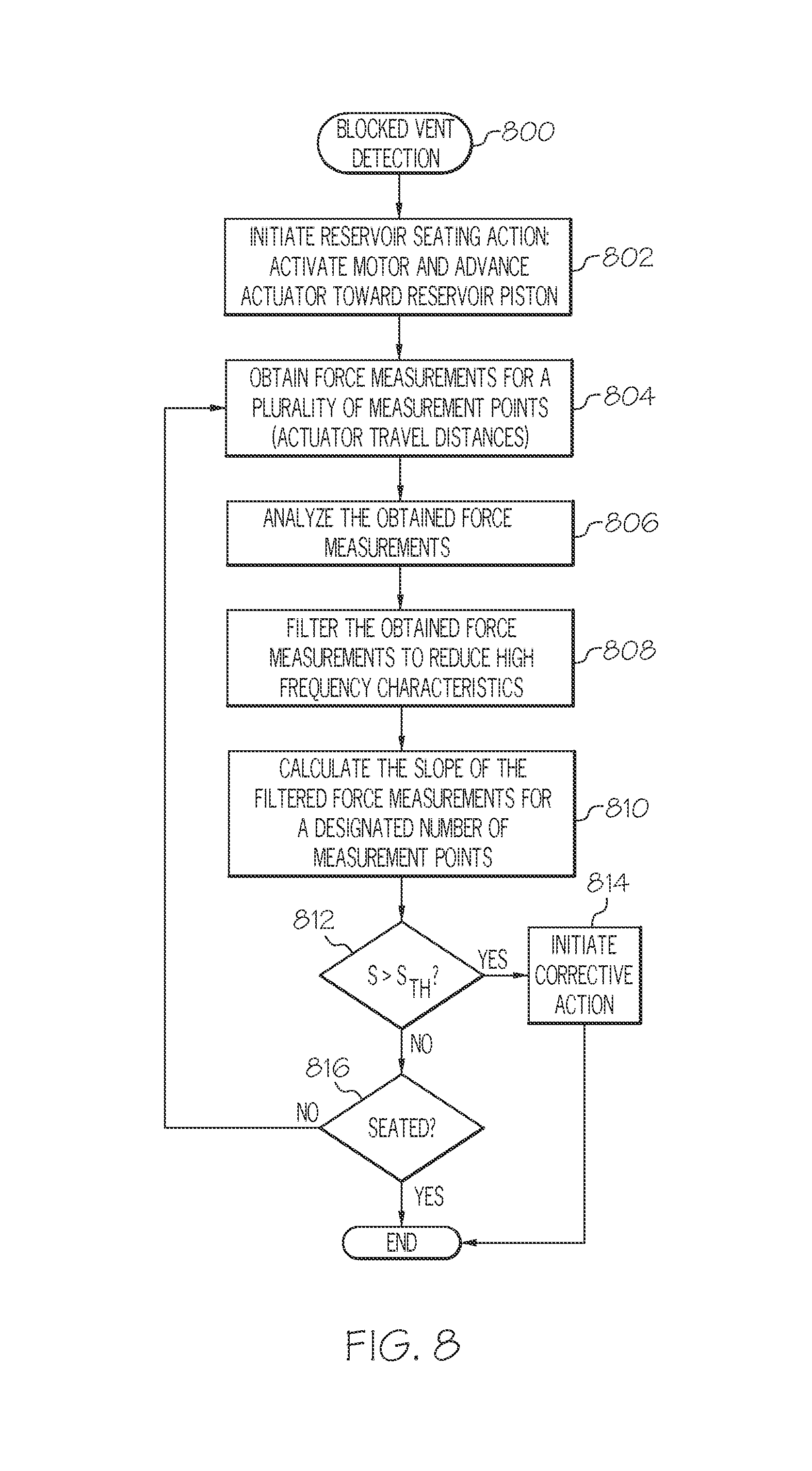
4. The method of claim 1, further comprising: obtaining a plurality of distance measurements during the reservoir seating action; calculating a slope of force-versus-distance for the plurality of distance measurements; and comparing the calculated slope of force-versus-distance to a threshold slope value, wherein the method determines that the vent in the reservoir cavity is blocked when the calculated slope is greater than the threshold slope value.
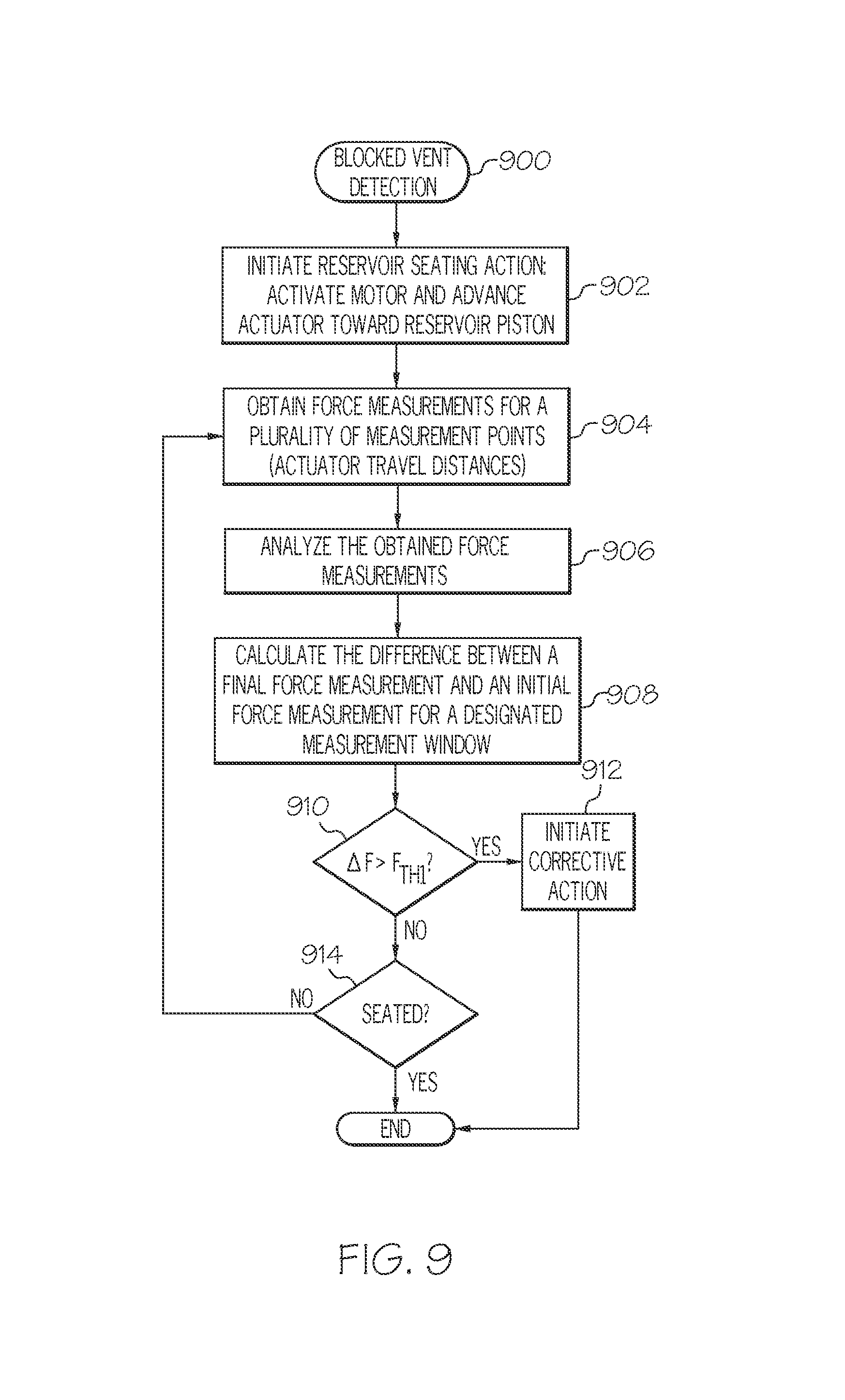
5. The method of claim 1, wherein: obtaining the plurality of force measurements comprises obtaining a first force measurement corresponding to a first distance measurement associated with the drive motor assembly, and obtaining a second force measurement corresponding to a second distance measurement associated with the drive motor assembly; and the method further comprises calculating a difference between the second force measurement and the first force measurement, wherein the method determines that the vent in the reservoir cavity is blocked when the calculated difference is greater than a threshold force value.
6. The method of claim 1, further comprising: filtering the obtained plurality of force measurements to reduce high frequency characteristics, wherein the determining is based on an analysis of the filtered force measurements.
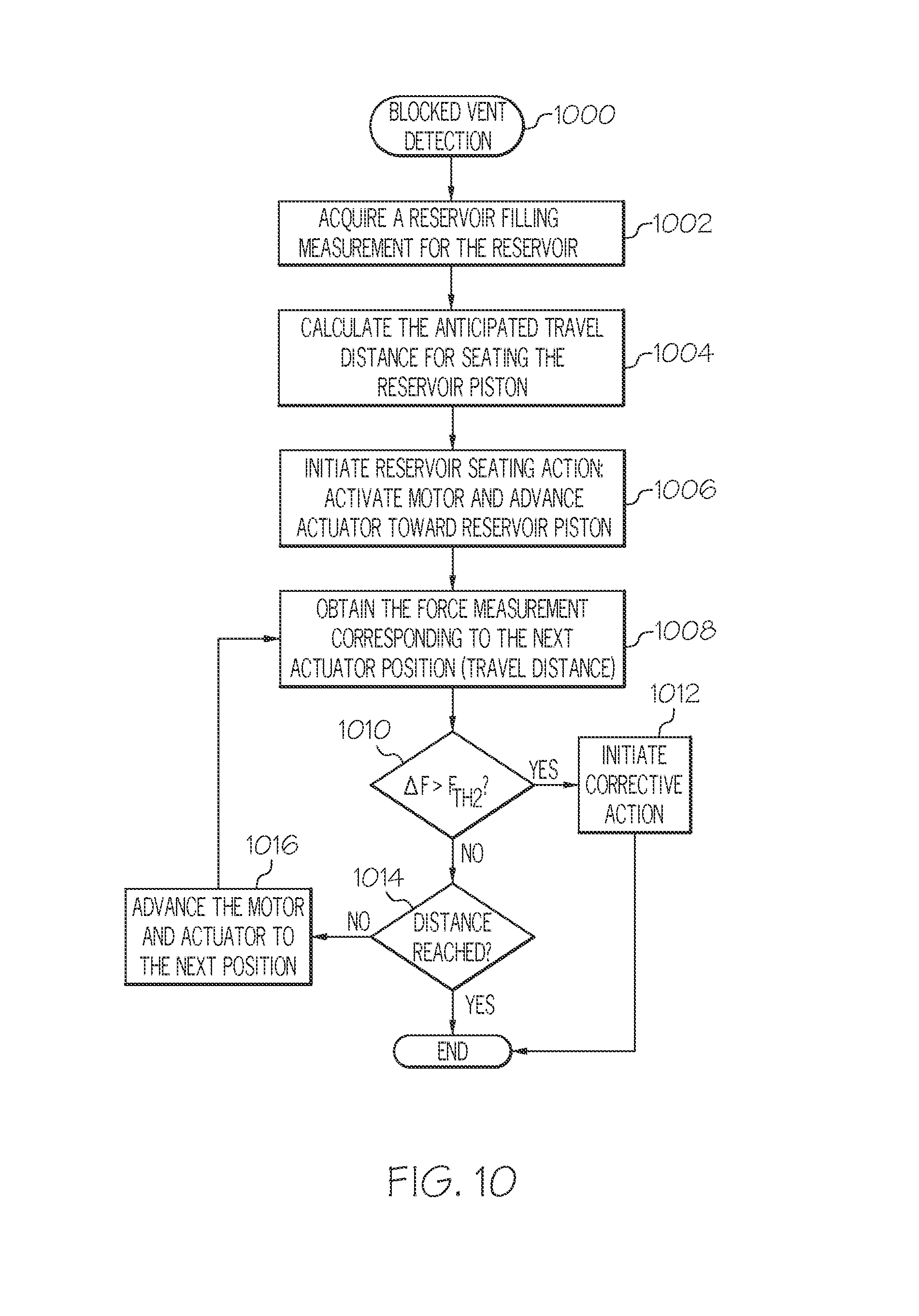
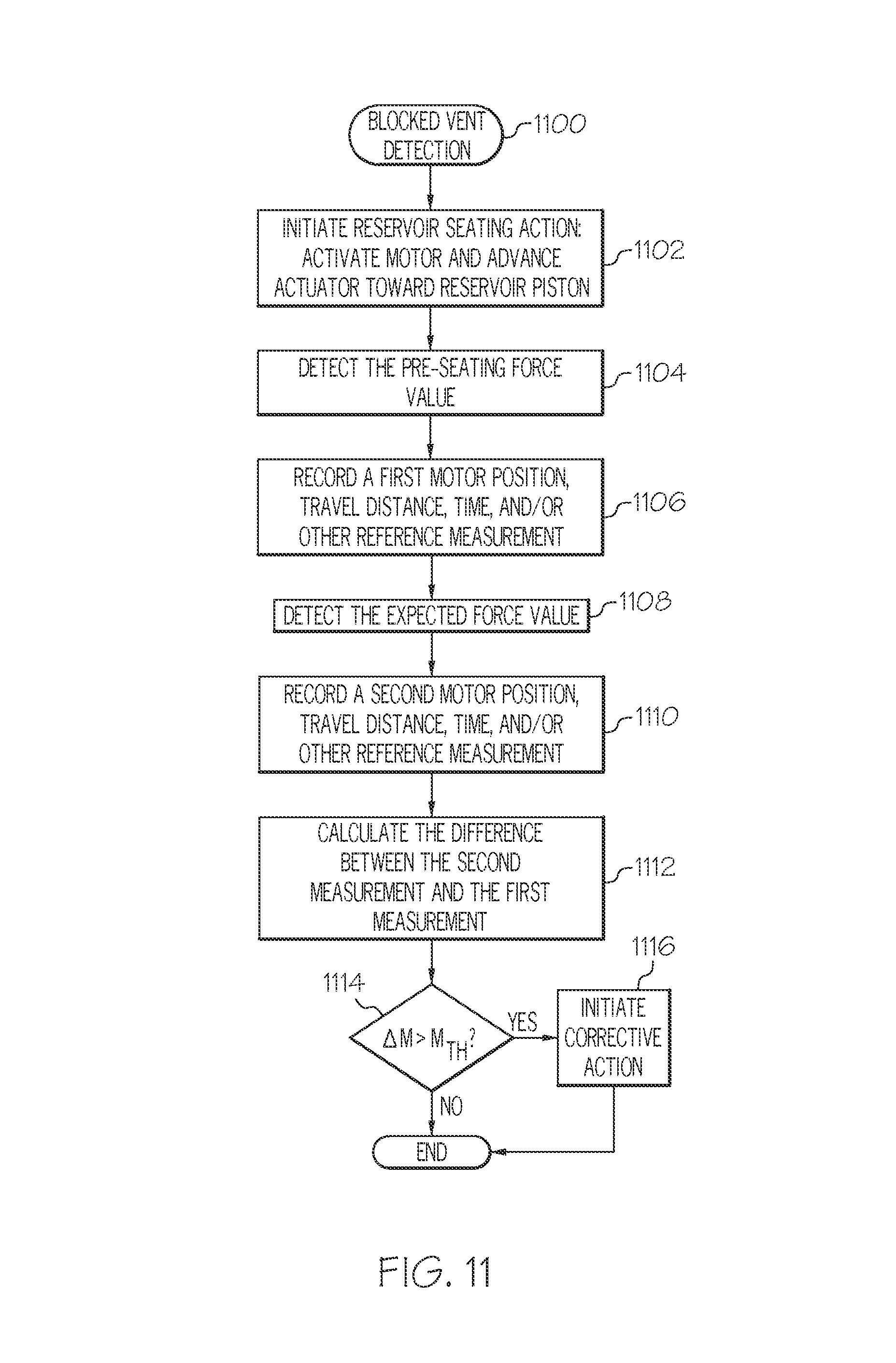
7. The method of claim 1, further comprising: acquiring a reservoir filling measurement for the fluid reservoir; calculating an anticipated travel distance for seating the piston of the fluid reservoir, based on the acquired reservoir filling measurement; ascertaining, before the anticipated travel distance is reached, that the initial force measurement is greater than the early detection threshold force value; and generating an alert in response to the ascertaining.
8. The method of claim 1, further comprising: detecting a pre-seating force value during the reservoir seating action; recording a first distance measurement corresponding to the detected pre-seating force value; thereafter, detecting an expected seating force value during the reservoir seating action; recording a second distance measurement corresponding to the detected expected seating force value; calculating a difference between the second distance measurement and the first distance measurement; and generating an alert when the difference is greater than a threshold seating distance.
9. The method of claim 1, further comprising: pausing the reservoir seating action; obtaining the initial force measurement while the reservoir seating action is paused; and generating an alert when the initial force measurement is greater than the early detection threshold force value.
10. The method of claim 1, further comprising: recording a first force measurement during the reservoir seating action; after recording the first force measurement, rewinding the drive motor assembly to achieve a rewound position; recording a second force measurement while the drive motor assembly is in the rewound position; and generating an alert when the second force measurement is less than the first force measurement by at least a threshold amount.
11. A method of operating a fluid infusion device comprising a drive motor assembly, an actuator coupled to the drive motor assembly, and a reservoir that accommodates a fluid reservoir having a piston, the method comprising: initiating a reservoir seating action intended to seat the actuator with the piston of the fluid reservoir; obtaining, for each of a plurality of travel distance measurement points associated with the reservoir seating action, a respective force measurement that is indicative of air pressure inside the reservoir cavity, resulting in a plurality of obtained force measurements; comparing an initial force measurement from the plurality of obtained force measurements to an early detection threshold force value; initiating processing of additional force measurements from the plurality of obtained force measurements and for at least two of the plurality of travel distance measurement points only when the initial force measurement is greater than the early detection threshold force value; determining that a vent for equalizing air pressure inside the reservoir cavity is blocked and preventing air in the reservoir cavity from venting externally, based on the processing of the additional force measurements, wherein the determining occurs before actual seating of the actuator in contact with the piston; and initiating corrective action for the fluid infusion device in response to determining that the vent in the reservoir cavity is blocked.
12. The method of claim 11, wherein initiating corrective action comprises generating an alert at the fluid infusion device.
13. The method of claim 11, wherein the processing comprises: calculating a slope of force-versus-distance for the additional force measurements; and comparing the calculated slope of force-versus-distance to a threshold slope value, wherein the method determines that the vent in the reservoir cavity is blocked when the calculated slope is greater than the threshold slope value.
14. The method of claim 11, wherein the processing comprises: calculating a difference between a first force measurement and a second force measurement, wherein the method determines that the vent in the reservoir cavity is blocked when the calculated difference is greater than a threshold force value.
15. The method of claim 11, further comprising: filtering the plurality of obtained force measurements to reduce high frequency characteristics, wherein the processing is performed on filtered force measurements.
16. The method of claim 11, further comprising: acquiring a reservoir filling measurement for the fluid reservoir; calculating an anticipated travel distance for seating the actuator with the piston of the fluid reservoir, based on the acquired reservoir filling measurement; ascertaining, before the anticipated travel distance is reached, that the initial force measurement is greater than the early detection threshold force value; and generating an alert in response to the ascertaining.
17. The method of claim 11, further comprising: detecting a pre-seating force value during the reservoir seating action; recording a first distance measurement corresponding to the detected pre-seating force value; thereafter, detecting an expected seating force value during the reservoir seating action; recording a second distance measurement corresponding to the detected expected seating force value; calculating a difference between the second distance measurement and the first distance measurement; and generating an alert when the difference is greater than a threshold seating distance.
18. The method of claim 11, further comprising: pausing the reservoir seating action; obtaining the initial force measurement while the reservoir seating action is paused; and generating an alert when the initial force measurement is greater than the early detection threshold force value.
19. The method of claim 11, further comprising: recording a first force measurement during the reservoir seating action; after recording the first force measurement, rewinding the actuator to achieve a rewound position; recording a second force measurement while the actuator is in the rewound position; and generating an alert when the second force measurement is less than the first force measurement by at least a threshold amount.
20. A device for delivering fluid to a user, the device comprising: a housing; a reservoir cavity within the housing to accommodate fluid reservoirs; a drive motor assembly in the housing to advance an actuator for a piston of a fluid reservoir; a force sensor associated with the drive motor assembly to generate output levels in response to force imparted thereto, the output levels corresponding to force measurements; and an electronics module coupled to the force sensor to process the output levels during a reservoir seating action intended to seat the actuator with the piston of the fluid reservoir by: obtaining a plurality of force measurements from the force sensor during the reservoir seating action, the plurality of force measurements indicating measures of force imparted to the force sensor during the reservoir seating action; comparing an initial force measurement from the plurality of force measurements to an early detection threshold force value; initiating an analysis of additional force measurements from the plurality of force measurements only when the initial force measurement is greater than the early detection threshold force value; determining that a vent for equalizing air pressure inside the reservoir cavity is blocked and preventing air in the reservoir cavity from venting externally, based on the analysis of the additional force measurements, wherein the determining occurs before actual seating of the actuator in contact with the piston; and initiating corrective action for the fluid infusion device in response to determining that the vent in the reservoir cavity is blocked.
21. The device of claim 20, wherein the electronics module initiates the corrective action by generating a user alert.
22. The device of claim 20, wherein, during the reservoir seating action, the electronics module: obtains a plurality of distance measurements; calculates a slope of force-versus-distance for the plurality of distance measurements; and compares the calculated slope of force-versus-distance to a threshold slope value, wherein the electronics module determines that the vent in the reservoir cavity is blocked when the calculated slope is greater than the threshold slope value.
23. The device of claim 20, wherein, during the reservoir seating action, the electronics module: obtains a first force measurement corresponding to a first distance measurement associated with the drive motor assembly; obtains a second force measurement corresponding to a second distance measurement associated with the drive motor assembly; and calculates a difference between the second force measurement and the first force measurement, wherein the electronics module determines that the vent in the reservoir cavity is blocked when the calculated difference is greater than a threshold force value.
24. The device of claim 20, wherein: the electronics module filters the obtained plurality of force measurements to reduce high frequency characteristics; and the determination made by the electronics module is based on an analysis of the filtered force measurements.
Description
TECHNICAL FIELD
Embodiments of the subject matter described herein relate generally to medical devices. More particularly, embodiments of the subject matter relate to fluid infusion devices such as personal insulin infusion pumps.
BACKGROUND
Portable medical devices are useful for patients that have conditions that must be monitored on a continuous or frequent basis. For example, diabetics are usually required to modify and monitor their daily lifestyle to keep their blood glucose (BG) in balance. Individuals with Type 1 diabetes and some individuals with Type 2 diabetes use insulin to control their BG levels. To do so, diabetics routinely keep strict schedules, including ingesting timely nutritious meals, partaking in exercise, monitoring BG levels daily, and adjusting and administering insulin dosages accordingly.
The prior art includes a number of fluid infusion devices and insulin pump systems that are designed to deliver accurate and measured doses of insulin via infusion sets (an infusion set delivers the insulin through a small diameter tube that terminates at, e.g., a cannula inserted under the patient's skin). In lieu of a syringe, the patient can simply activate the insulin pump to administer an insulin bolus as needed, for example, in response to the patient's high BG level.
A typical infusion pump includes a housing, which encloses a pump drive system, a fluid containment assembly, an electronics system, and a power supply. The pump drive system typically includes a small drive motor or motor assembly (DC, stepper, solenoid, or other varieties) and drive train components such as gears, screws, and levers that convert rotational motor motion to a translational displacement of a stopper or piston of a fluid reservoir. The fluid containment assembly typically includes the fluid reservoir with the actuation piston, tubing, and a catheter or infusion set to create a fluid path for carrying medication from the reservoir to the body of a user. The electronics system regulates power from the power supply to the motor. The electronics system may include programmable controls to operate the motor continuously or at periodic intervals to obtain a closely controlled and accurate delivery of the medication over an extended period.
Some fluid infusion devices use sensors and alarm features designed to detect and indicate certain operating conditions, such as non-delivery of the medication to the patient due to a fluid path occlusion. In this regard, a force sensor can be used in a fluid infusion device to detect the amount of force imparted by the motor assembly and/or an actuator to the piston of the fluid reservoir. The force sensor in such a fluid infusion device could be positioned at the end of the drive motor assembly that actuates a rotatable drive screw, which moves an actuator, which in turn advances the piston of the reservoir. With such an arrangement, the force applied to the force sensor by the drive motor assembly is proportional to the pressure applied to the piston as a result of power supplied to the drive system to advance the piston. Thus, when a certain force threshold (a set point corresponding to an occlusion condition) is reached, the fluid infusion device is triggered to generate an alarm to warn the user.
Some fluid infusion devices use replaceable fluid reservoirs that are secured in the reservoir cavity of the device and actuated by the drive assembly. One form of infusion pump utilizes a removable threaded cap that accommodates replacement and refilling of fluid reservoirs, and that is used to seat and secure the fluid reservoir in the housing of the pump. Assuming that the pump had previously completed a rewind operation, the user unscrews the threaded cap to remove an empty reservoir, refills the reservoir or replaces the old reservoir with a new reservoir, and reinstalls the threaded cap to secure the filled reservoir in place. After installing a reservoir, the pump is operated to perform a seating action during which the actuator is advanced forward until it reaches and seats with the piston of the fluid reservoir. The force sensor may be used during the seating action to detect when proper seating has occurred.
The reservoir cavity is typically sealed to inhibit ingress of fluid and contaminants, such that the fluid reservoir and electronics inside the housing remain protected. Although sealed to inhibit fluid and particulates, the reservoir cavity may include a vent structure or element that allows air to flow into and out of the reservoir cavity. The reservoir cavity vent is desirable to equalize the pressure inside the reservoir cavity, regardless of the position of the reservoir actuator. If this vent is blocked, however, pressure could increase inside the reservoir cavity during seating operations because the forward advance of the actuator reduces the interior volume of the reservoir cavity, which in turn results in increased pressure (due to the unvented and sealed state of the reservoir cavity). Unpredictable buildup of pressure in this manner is undesirable because it can impact the accuracy of the reservoir seating operation, which relies on force measurements as mentioned above.
Accordingly, it is desirable to have an improved reservoir seating technique for fluid infusion devices. In addition, it is desirable to have a methodology for detecting a blocked reservoir cavity vent during a reservoir seating operation. Furthermore, other desirable features and characteristics will become apparent from the subsequent detailed description and the appended claims, taken in conjunction with the accompanying drawings and the foregoing technical field and background.
BRIEF SUMMARY
A method of operating a fluid infusion device is presented here. An exemplary embodiment of the device includes a drive motor assembly, a force sensor associated with the drive motor assembly, and a reservoir cavity that accommodates fluid reservoirs. In accordance with certain exemplary embodiments, the method obtains a plurality of force measurements for a reservoir seating action of the drive motor assembly, the plurality of force measurements indicating measures of force imparted to the force sensor during the reservoir seating action. The method continues by determining that a vent in the reservoir cavity is blocked, based on an analysis of the plurality of force measurements, and by initiating corrective action for the fluid infusion device in response to determining that the vent in the reservoir cavity is blocked.
Also presented here is another exemplary embodiment of a method of operating a fluid infusion device. The device includes a drive motor assembly, an actuator coupled to the drive motor assembly, and a reservoir cavity that accommodates a fluid reservoir having a piston. The method begins by initiating a reservoir seating action intended to seat the actuator with the piston of the fluid reservoir. The method continues by obtaining, for each of a plurality of travel distance measurement points associated with the reservoir seating action, a respective force measurement that is indicative of pressure inside the reservoir cavity. The method continues by processing force measurements for at least two of the plurality of travel distance measurement points, determining that a vent in the reservoir cavity is blocked, based on the processing, and initiating corrective action for the fluid infusion device in response to determining that the vent in the reservoir cavity is blocked.
An exemplary embodiment of a device for delivering fluid to a user is also presented here. The device includes a housing, a reservoir cavity within the housing to accommodate fluid reservoirs, a drive motor assembly in the housing to advance an actuator for a piston of a fluid reservoir, a force sensor associated with the drive motor assembly to generate output levels in response to force imparted thereto, the output levels corresponding to force measurements, and an electronics module coupled to the force sensor to process the output levels during a reservoir seating action intended to seat the actuator with the piston of the fluid reservoir. The electronics module obtains a plurality of plurality of force measurements from the force sensor, determines that a vent in the reservoir cavity is blocked, based on an analysis of the plurality of force measurements, and initiates corrective action for the fluid infusion device in response to determining that the vent in the reservoir cavity is blocked.
This summary is provided to introduce a selection of concepts in a simplified form that are further described below in the detailed description. This summary is not intended to identify key features or essential features of the claimed subject matter, nor is it intended to be used as an aid in determining the scope of the claimed subject matter.
BRIEF DESCRIPTION OF THE DRAWINGS
A more complete understanding of the subject matter may be derived by referring to the detailed description and claims when considered in conjunction with the following figures, wherein like reference numbers refer to similar elements throughout the figures.
FIG. 1 is a schematic representation of an embodiment of a fluid infusion device;
FIG. 2 is an exploded perspective view of the fluid infusion device shown in FIG. 1;
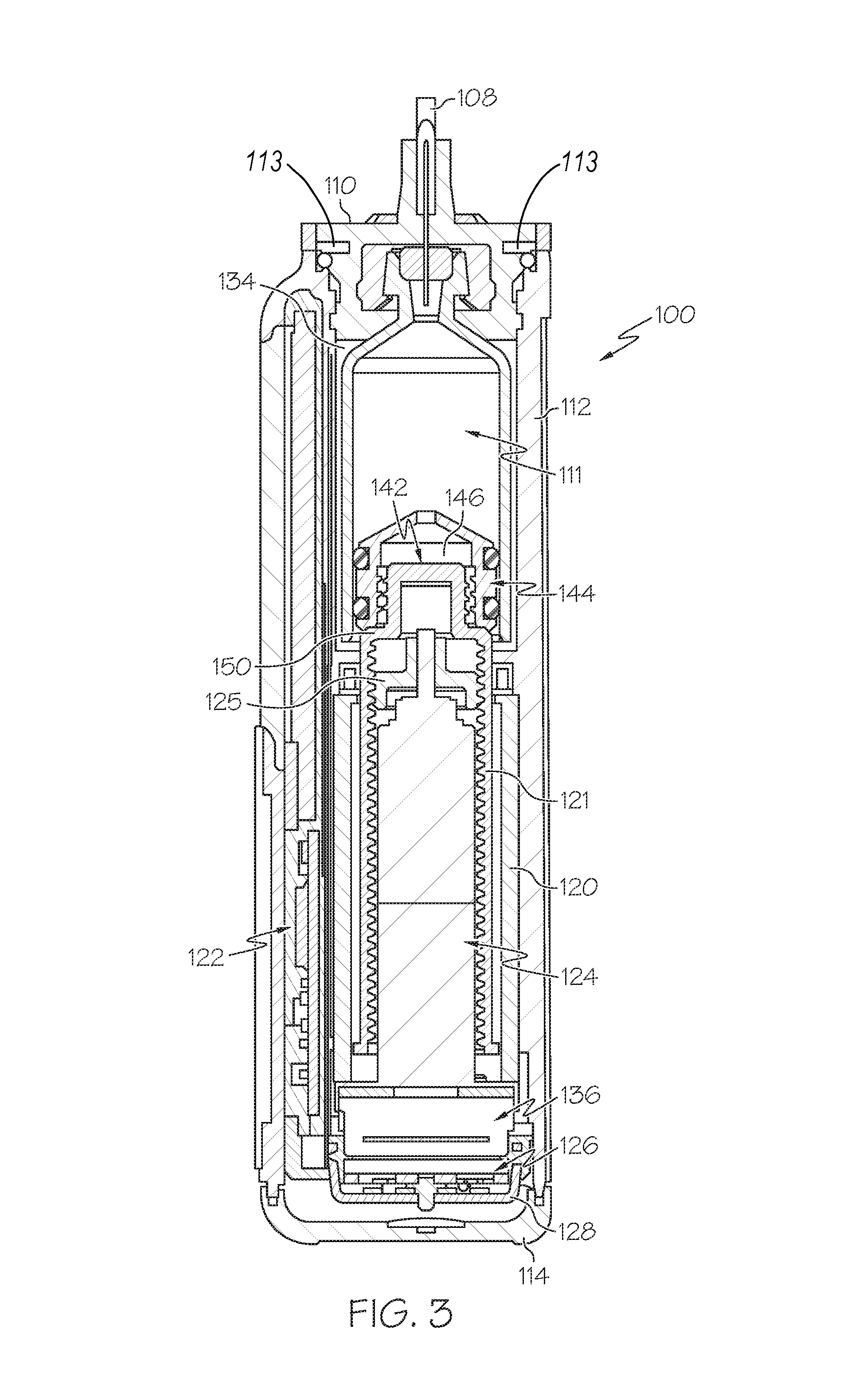
FIG. 3 is a cross sectional view of the fluid infusion device shown in FIG. 1, corresponding to a cross section taken longitudinally through the drive motor assembly and the fluid reservoir;
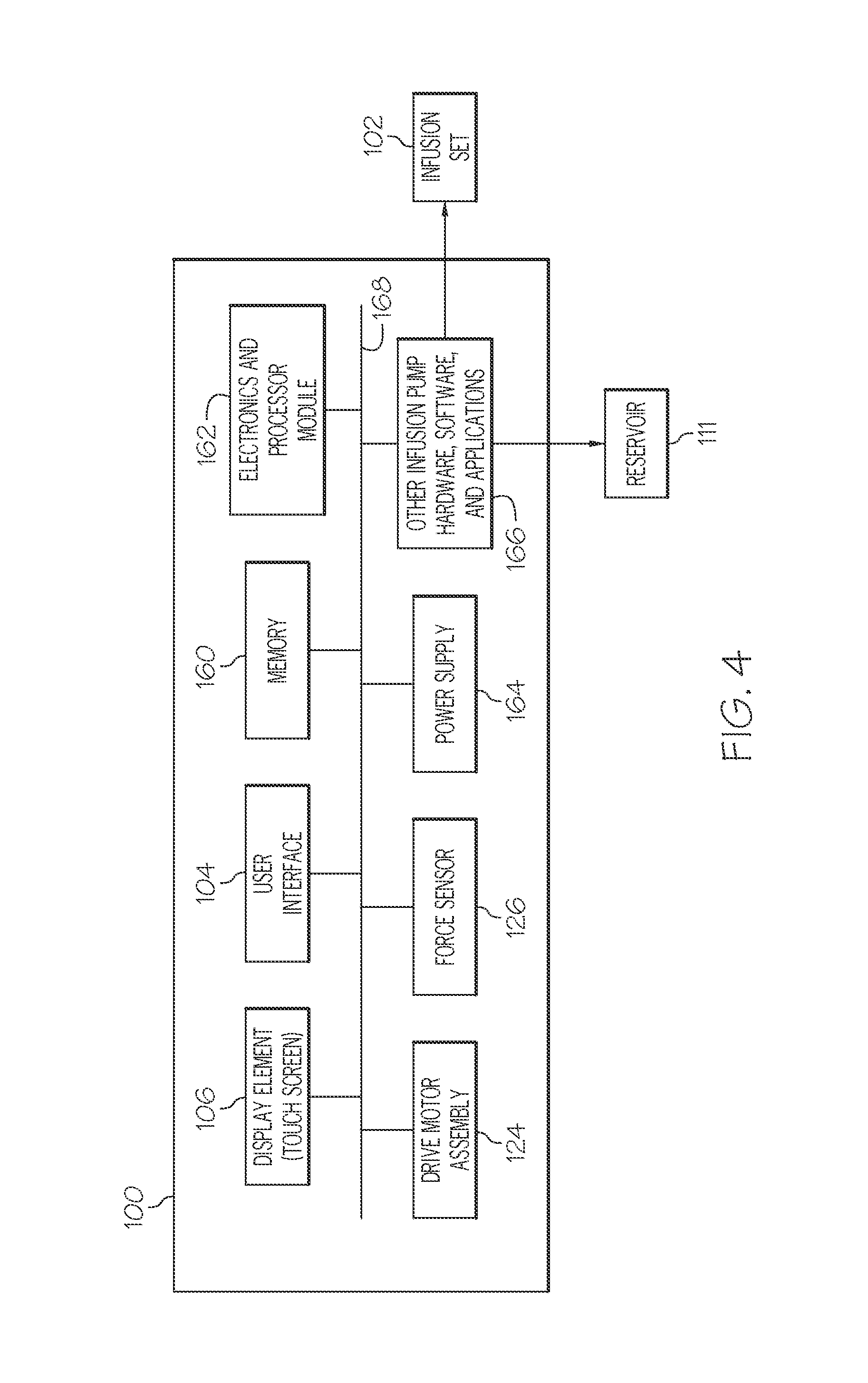
FIG. 4 is a schematic block diagram representation of an embodiment of a fluid infusion device;
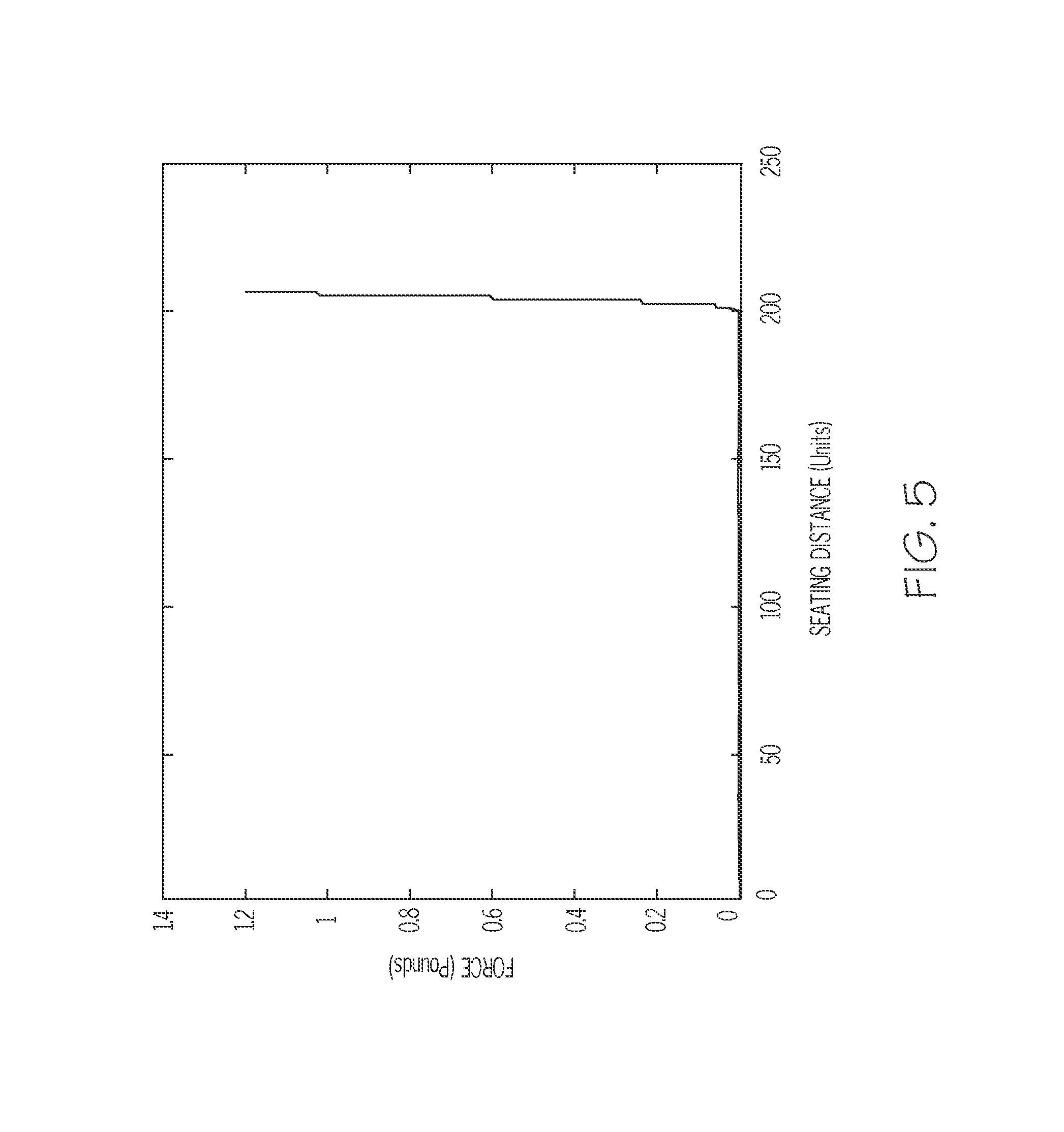
FIG. 5 is a plot of force versus slide actuator position (or an equivalent metric) during a reservoir seating action performed under normal conditions;
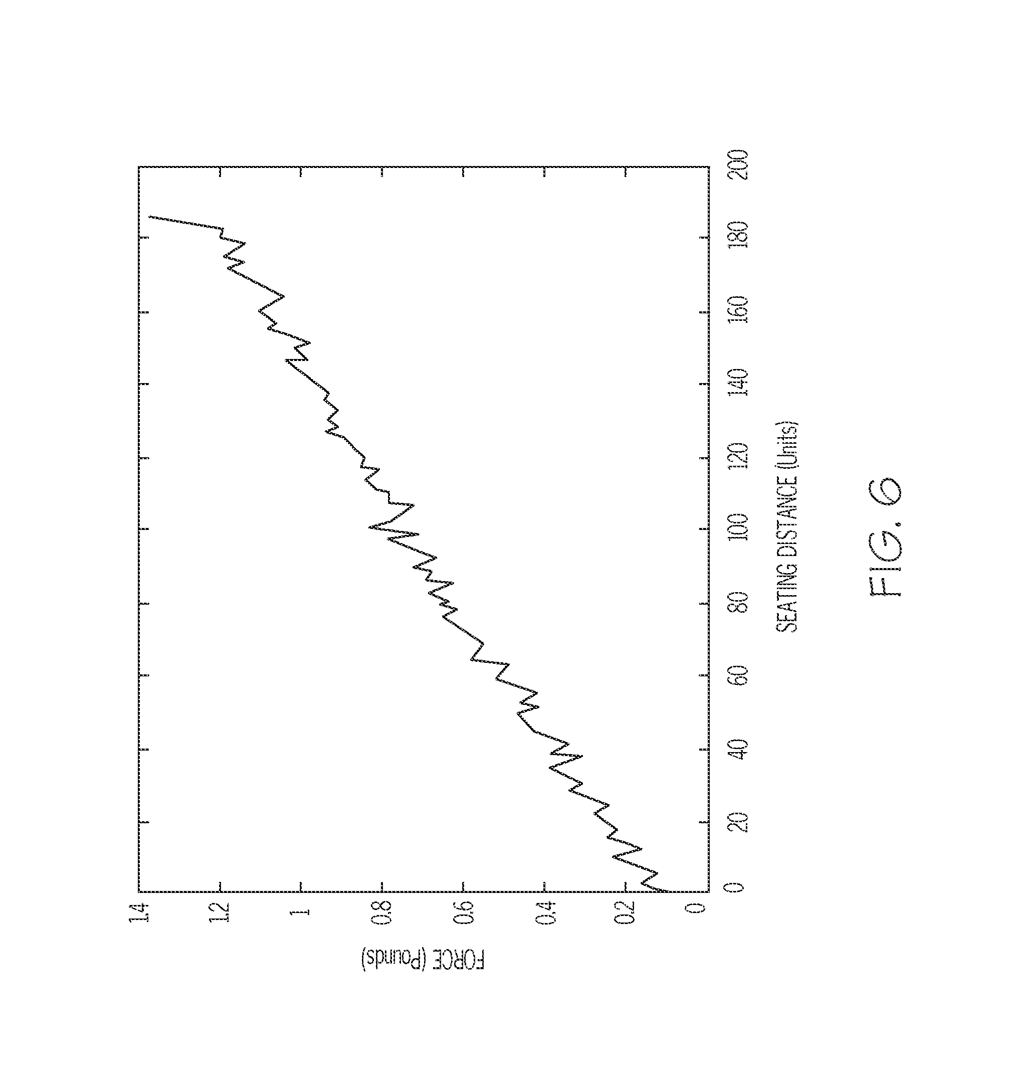
FIG. 6 is a plot of force versus slide actuator position (or an equivalent metric) during a reservoir seating action performed under a blocked vent condition; and
FIG. 7 is a flow chart that illustrates an exemplary embodiment of a reservoir seating process; and
FIGS. 8-13 are flow charts that illustrate various exemplary embodiments of a blocked vent detection process.
DETAILED DESCRIPTION
The following detailed description is merely illustrative in nature and is not intended to limit the embodiments of the subject matter or the application and uses of such embodiments. As used herein, the word "exemplary" means "serving as an example, instance, or illustration." Any implementation described herein as exemplary is not necessarily to be construed as preferred or advantageous over other implementations. Furthermore, there is no intention to be bound by any expressed or implied theory presented in the preceding technical field, background, brief summary or the following detailed description.
Techniques and technologies may be described herein in terms of functional and/or logical block components, and with reference to symbolic representations of operations, processing tasks, and functions that may be performed by various computing components or devices. It should be appreciated that the various block components shown in the figures may be realized by any number of hardware, software, and/or firmware components configured to perform the specified functions. For example, an embodiment of a system or a component may employ various integrated circuit components, e.g., memory elements, digital signal processing elements, logic elements, look-up tables, or the like, which may carry out a variety of functions under the control of one or more microprocessors or other control devices.
For the sake of brevity, conventional techniques related to infusion system operation, insulin pump and/or infusion set operation, blood glucose sensing and monitoring, force sensors, signal processing, and other functional aspects of the systems (and the individual operating components of the systems) may not be described in detail here. Examples of infusion pumps and/or related pump drive systems used to administer insulin and other medications may be of the type described in, but not limited to, U.S. Pat. Nos. 4,562,751; 4,678,408; 4,685,903; 5,080,653; 5,505,709; 5,097,122; 6,485,465; 6,554,798; 6,558,351; 6,659,980; 6,752,787; 6,817,990; 6,932,584; and 7,621,893; which are herein incorporated by reference.
The subject matter described here relates to a fluid infusion device of the type used to treat a medical condition of a patient. The infusion device is used for infusing fluid into the body of a user. The non-limiting examples described below relate to a medical device used to treat diabetes (more specifically, an insulin pump), although embodiments of the disclosed subject matter are not so limited. Accordingly, the infused fluid is insulin in certain embodiments. In alternative embodiments, however, many other fluids may be administered through infusion such as, but not limited to, disease treatments, drugs to treat pulmonary hypertension, iron chelation drugs, pain medications, anti-cancer treatments, medications, vitamins, hormones, or the like.
FIG. 1 is a plan view of an exemplary embodiment of a fluid infusion device 100. FIG. 1 also shows an infusion set 102 coupled to the fluid infusion device 100. The fluid infusion device 100 is designed to be carried or worn by the patient. The fluid infusion device 100 may leverage a number of conventional features, components, elements, and characteristics of existing fluid infusion devices. For example, the fluid infusion device 100 may incorporate some of the features, components, elements, and/or characteristics described in U.S. Pat. Nos. 6,485,465 and 7,621,893, the relevant content of which is incorporated by reference herein.
This embodiment shown in FIG. 1 includes a user interface 104 that includes several buttons that can be activated by the user. These buttons can be used to administer a bolus of insulin, to change therapy settings, to change user preferences, to select display features, and the like. Although not required, the illustrated embodiment of the fluid infusion device 100 includes a display element 106. The display element 106 can be used to present various types of information or data to the user, such as, without limitation: the current glucose level of the patient; the time; a graph or chart of the patient's glucose level versus time; device status indicators; alerts, alarms, error indicators, or other messages; etc. In some embodiments, the display element 106 is realized as a touch screen display element and, therefore, the display element 106 also serves as a user interface component.
The fluid infusion device 100 accommodates a fluid reservoir (hidden from view in FIG. 1) for the fluid to be delivered to the user. A length of tubing 108 is the flow path that couples the fluid reservoir to the infusion set 102. The tubing 108 extends from the fluid infusion device 100 to the infusion set 102, which provides a fluid pathway with the body of the user. A removable cap or fitting 110 is suitably sized and configured to accommodate replacement of fluid reservoirs (which are typically disposable) as needed. In this regard, the fitting 110 is designed to accommodate the fluid path from the fluid reservoir to the tubing 108.
In certain embodiments, the fitting 110 forms a seal with the housing of the fluid infusion device 100, to inhibit ingress of fluid and other potential contaminants into the reservoir cavity. For example, the fitting 110 may include or cooperate with a sealing element that forms the seal when the fitting 110 is threaded onto the housing. Moreover, for the embodiment described here, the fitting 110 includes or cooperates with at least one vent 113 (see FIG. 3) to enable air to pass into and out of the reservoir cavity, thus equalizing the pressure inside the reservoir cavity. In practice, the vent 113 may be implemented as a gas permeable membrane that allows gas (air) to pass while blocking the passage of liquids and solids. In some embodiments, the fluid infusion device 100 may include other venting structures or elements (in lieu of or in addition to a membrane vent) for the reservoir cavity.
FIG. 2 is an exploded perspective view of the fluid infusion device 100. For the sake of brevity and simplicity, FIG. 2 is a simplified depiction of the fluid infusion device 100 that does not include all of the elements, components, and features that would otherwise be present in a typical embodiment. It should be appreciated that a deployed implementation of the fluid infusion device 100 will include additional features, components, and elements that are not shown in the figures.
The embodiment of the fluid infusion device 100 illustrated in FIG. 2 includes a housing 112 and a housing end cap 114 that is coupled to an end 116 of the housing 112 to enclose components within the housing 112. These internal components include, without limitation: a battery tube subassembly 118; a sleeve 120; a slide actuator 121; an electronics assembly 122; a drive motor assembly 124 having a drive screw 125; a force sensor 126; and a motor support cap 128. FIG. 2 also depicts some components that are located outside the housing 112, namely, a keypad assembly 130 and a graphic keypad overlay 132 for the keypad assembly 130. The keypad assembly 130 and the graphic keypad overlay 132 may be considered to be part of the user interface 104 of the fluid infusion device 100. The outer edge of the motor support cap 128 is attached to the interior side of the housing 112, and the motor support cap 128 contacts the force sensor 126 to remove assembly tolerances from the drive motor assembly 124. FIG. 2 also depicts an exemplary fluid reservoir 111, which is inserted into a reservoir cavity defined within the housing 112. The reservoir cavity is configured, sized, and shaped to accommodate fluid reservoirs, and the fluid reservoir 111 is maintained in the reservoir cavity using the fitting 110. The electronics assembly 122 may include a suitably configured electronics module (not shown in FIG. 2; see FIG. 4 and related description below), which may include or cooperate with a power supply, at least one memory element, at least one processor, processing logic, and device software, firmware, and application programs.
FIG. 3 is a cross sectional view of the fluid infusion device 100, corresponding to a cross section taken longitudinally through the drive motor assembly 124 and the fluid reservoir 111. FIG. 3 depicts the state of the fluid infusion device 100 after the fluid reservoir 111 has been inserted into the reservoir cavity 134 and after the fitting 110 has been secured to the housing 112 to hold the fluid reservoir 111 in place. While certain embodiments accommodate disposable, prefilled reservoirs, alternative embodiments may use refillable cartridges, syringes or the like. A cartridge can be prefilled with insulin (or other drug or fluid) and inserted into the housing 112. Alternatively, a cartridge could be filled by the user using an appropriate adapter and/or any suitable refilling device.
When assembled as shown in FIG. 3, the drive motor assembly 124 is located in the housing 112. The force sensor 126 is operatively associated with the drive motor assembly 124. For this particular embodiment, the force sensor 126 is coupled to the drive motor assembly 124, and it is located between a base end of the drive motor assembly 124 and the motor support cap 128. In one implementation, the force sensor 126 is affixed to the base end of the drive motor assembly 124 such that the force sensor 126 reacts when it bears against the motor support cap 128. In another implementation, the force sensor 126 is affixed to the housing end cap 114 such that the force sensor 126 reacts when the drive motor assembly 124 bears against the force sensor 126. This configuration and arrangement of the drive motor assembly 124 and the force sensor 126 allows the force sensor 126 to react to forces imparted thereto by the drive motor assembly 124, forces imparted to the drive motor assembly 124 via the fluid pressure of the fluid reservoir 111, and/or forces imparted to the drive motor assembly 124 via air pressure inside the reservoir cavity 134, which can result when the vent 113 is blocked.
The drive motor assembly 124 includes an electric motor 136 that is actuated and controlled by the electronics module of the fluid infusion device 100. The motor 136 is preferably realized as a stepper motor that rotates in a stepwise or discrete manner corresponding to the desired number of fluid delivery strokes. Alternatively, the motor 136 could be a DC motor, a solenoid, or the like. The motor 136 may optionally include an encoder (not shown), which cooperates with the electronics module of the fluid infusion device 100 to monitor the number of motor rotations or portions thereof. This in turn can be used to accurately determine the position of the slide actuator 121, thus providing information relating to the amount of fluid dispensed from the fluid reservoir 111.
The drive motor assembly 124 can be mounted in the housing 112 using an appropriate mounting feature, structure, or element. Alternatively, the mounting could be accomplished using a shaft bearing and leaf spring or other known compliance mountings.
The illustrated embodiment of the drive motor assembly 124 includes a drive member (such as the externally threaded drive gear or drive screw 125) that engages an internally threaded second drive member (such as the slide actuator 121) having a coupler 142. The coupler 142 may be attached to or integrated with the slide actuator 121, as depicted in FIG. 2 and FIG. 3. The slide actuator 121 is sized to fit within the reservoir cavity 134 of the fluid infusion device 100, which enables the slide actuator 121 to operatively cooperate with the fluid reservoir 111. The fluid reservoir 111 includes a plunger or piston 144 with at least one sealing element or feature (e.g., one or more O-rings, integral raised ridges, or a washer) for forming a fluid and air tight seal with the inner wall of the fluid reservoir 111. As mentioned previously, the fluid reservoir 111 is secured into the housing 112 with the fitting 110, which also serves as the interface between the fluid reservoir 111 and the infusion set tubing 108. For this embodiment, the piston 144 is in contact with a linear actuation member, such as the slide actuator 121. For example, the piston 144 may have a female portion 146 that receives the coupler 142 carried by the slide actuator 121. The female portion 146 is positioned at the end face of the piston 144, and it is sized to receive and accommodate the coupler 142. In certain embodiments, the female portion 146 includes a threaded cavity that engages external threads of the coupler 142.
Referring to FIG. 3, rotation of the drive shaft of the motor 136 results in corresponding rotation of the drive screw 125, which in turn moves the slide actuator 121 forward or backward via the threaded engagement. Thus, rotation of the drive screw 125 results in axial displacement of the slide actuator 121 and, therefore, axial displacement of the coupler 142. Such displacement of the coupler 142 moves the piston 144 (upward in FIG. 3) to deliver a predetermined or commanded amount of medication or liquid from the fluid infusion device 100. In this manner, the drive motor assembly 124 is configured to regulate delivery of fluid by actuating the piston 144 (under the control of the electronics module and/or control system of the fluid infusion device 100). As described above, if a stepper motor is employed, then the drive motor assembly 124 can regulate delivery of fluid from the fluid infusion device 100 in discrete actuation or delivery strokes. The fluid infusion device 100 can employ the sleeve 120 or an equivalent feature (such as an anti-rotation key) to inhibit rotation of the drive motor assembly 124, which might otherwise result from torque generated by the motor 136. In some embodiments, the drive shaft of the drive motor assembly 124, the drive screw 125, and the slide actuator 121 are all coaxially centered within the longitudinal axis of travel of the piston 144. In certain alternative embodiments, one or more of these components may be offset from the center of the axis of travel and yet remain aligned with the axis of travel, which extends along the length of the fluid reservoir 111.
As mentioned above, certain embodiments of the fluid infusion device 100 accommodate removable and replaceable fluid reservoirs. When the slide actuator 121 and, therefore, the piston 144 of the fluid reservoir 111 are in their fully extended positions, the piston 144 has forced most, if not all, of the fluid out of the fluid reservoir 111. After the piston 144 has reached the end of its travel path, indicating that the fluid reservoir 111 has been depleted, the fluid reservoir 111 may be removed such that the female portion 146 of the piston 144 disengages from the coupler 142 of the slide actuator 121. After the empty (or otherwise used) fluid reservoir 111 is removed, the electronics module or control system of the fluid infusion device 100 initiates a rewind operation during which the motor 136 rotates in the reverse direction to rewind the slide actuator 121 back to its fully retracted position. Thereafter, a new or refilled fluid reservoir 111 can be installed, seated, and primed for use. In this regard, an embodiment provides for advancement of the slide actuator 121 upon the insertion of a fluid reservoir 111 into the housing 112. The slide actuator 121 advances during a reservoir seating action until its coupler 142 comes into contact with the piston 144 of the fluid reservoir 111. In alternative embodiments having a threaded piston engagement, the slide actuator 121 advances until the threads of the coupler 142 engage the threads in the female portion 146 of the piston 144. When the threads engage in this fashion, they need not do so by twisting. Rather, they may ratchet over one another. In operation, the force sensor 126 may be used to determine when the slide actuator 121 contacts the piston 144, when the coupler 142 is properly seated in the female portion 146, and/or when the fluid reservoir 111 has been primed and is ready to deliver measured doses of fluid.
Although the illustrated embodiment employs a coaxial or inline drive system, alternative configurations could be utilized. For example, a drive system that uses a lead screw, a drive nut, and actuation arms (of the type described in U.S. Pat. No. 6,485,465) may be employed, with the force sensor 126 positioned in an appropriate location. In various embodiments, the drive train might include one or more lead screws, cams, ratchets, jacks, pulleys, pawls, clamps, gears, nuts, slides, bearings, levers, beams, stoppers, plungers, sliders, brackets, guides, bearings, supports, bellows, caps, diaphragms, bags, heaters, or the like. Moreover, although the illustrated embodiment employs a sensor positioned at the end of the fluid drive train, other arrangements could be deployed. For example, a sensor could be placed at or near the front end of the fluid drive train.
In particular embodiments, the force sensor 126 is used to detect when the slide actuator 121 contacts the piston 144. Thus, after the fluid reservoir 111 is placed into the fluid infusion device 100, the motor 136 is activated to move the slide actuator 121 toward the fluid reservoir 111 to engage the piston 144. In this regard, when a shoulder region 150 (see FIG. 3) of the slide actuator 121 first contacts the piston 144, the electronics module detects an increase in force imparted to the force sensor 126. The measured force continues to increase as the motor 136 continues to drive forward, in response to the fluid resistance in the fluid reservoir 111. When the slide actuator 121 is properly seated with the piston 144, the measured force increases to the seating threshold level. During the seating operation, if the measured force exceeds this seating threshold, the motor 136 is stopped until further commands are issued. The seating threshold is generally about 1.5 pounds. In alternative embodiments, higher or lower seating thresholds may be used depending on the force required to mate the slide actuator 121 with the piston 144, the force required to urge fluid from the fluid reservoir 111, the speed of the motor 136, the accuracy and resolution of the force sensor 126, or the like.
It should be appreciated that other force thresholds can be used for other purposes. During priming of fluid reservoirs, for example, a threshold of about 4.0 pounds is used. In some embodiments, levels greater than about 5.0 pounds are used to detect shock loads that may be damaging to the fluid infusion device 100.
The force sensor 126 is configured to react in response to force imparted thereto. In this regard, electrical, mechanical, magnetic, and/or other measurable or detectable characteristics of the force sensor 126 vary in accordance with the amount of force applied to the force sensor 126. In practice, the force sensor 126 might implement or otherwise leverage known sensor technologies, such as the sensor technology described in U.S. Pat. No. 6,485,465. As shown in FIG. 2, the force sensor 126 includes at least one electrical lead 154 that is electrically coupled to the electronics module (or controller) of the fluid infusion device 100. Alternatively, the force sensor 126 could use wireless data communication technology to provide force-related data to the electronics module. In certain implementations, the force sensor 126 is suitably configured to indicate or generate a plurality of different output levels that can be monitored and/or determined by the electronics module. In practice, the output levels obtained from the force sensor 126 are initially conveyed as analog voltages or analog currents, and the electronics module includes an analog-to-digital converter that transforms a sampled analog voltage into a digital representation. Conversion of sensor voltage into the digital domain is desirable for ease of processing, comparison to threshold values, and the like.
In particular embodiments, the force sensor 126 is realized as an electromechanical component having at least one variable resistance that changes as the force applied to the force sensor 126 changes. In alternative embodiments, the force sensor 126 is a capacitive sensor, a piezoresistive sensor, a piezoelectric sensor, a magnetic sensor, an optical sensor, a potentiometer, a micro-machined sensor, a linear transducer, an encoder, a strain gauge, or the like, and the detectable parameter or characteristic might be compression, shear, tension, displacement, distance, rotation, torque, force, pressure, or the like. In practice, changing characteristics of the force sensor 126 are associated with output signal characteristics that are responsive to a physical parameter to be measured. Moreover, the range and resolution of the monitored output signal provides for the desired number of output levels (e.g., different states, values, quantities, signals, magnitudes, frequencies, steps, or the like) across the range of measurement. For example, the force sensor 126 might generate a low or zero value when the applied force is relatively low, a high or maximum value when the applied force is relatively high, and intermediate values when the applied force is within the detectable range.
In certain exemplary embodiments, the electronics module of the fluid infusion device 100 maintains a constant supply voltage across the force sensor 126, and the monitored output signal of the force sensor 126 is a signal current that passes through a resistive material of the force sensor 126. Thus, the signal current varies with the amount of force applied to the force sensor 126 because the resistance of the force sensor 126 varies with force and the supply voltage across the force sensor 126 is constant. The electronics module converts the monitored signal current into a signal voltage, which is then used as an indication of the force imparted to the force sensor 126 (which may be caused by the drive motor assembly 124, by fluid pressure in the fluid reservoir 111, by impact experienced by the fluid infusion device 100, by unexpected pressure buildup inside the reservoir cavity 134, etc.). In alternative embodiments, a constant supply current is used and the signal voltage across the force sensor 126 varies with force (fluid pressure).
In certain embodiments, sensor measurements are taken prior to commanding the drive system to deliver fluid, and soon after the drive system has stopped delivering fluid. In alternative embodiments, sensor data is collected on a continuous basis at a particular sampling rate (for example, 10.0 Hz, 3.0 Hz, once every 10 seconds, once a minute, once every five minutes, or the like). In further alternative embodiments, the sensor data is only collected prior to commanding the drive system to deliver fluid. In still further alternative embodiments, sensor data is collected during fluid delivery (during delivery strokes and/or between delivery strokes) and during other operations that involve movement of the slide actuator 121.
In practice, the force sensor 126 and associated electronics are designed to measure forces between about zero pounds and about five pounds with a desired resolution of about 0.01 pounds. In preferred embodiments, the force sensor 126 and associated electronics provide a relatively linear voltage output in response to forces applied to the force sensor 126 by one or more drive train components. In alternative embodiments, the range and resolution of the force sensor 126 might vary from that specified above. Furthermore, the sensor range and/or resolution may vary in accordance with the concentration of the fluid being delivered, the diameter of the fluid reservoir 111, the diameter of the fluid path, the nominal range of force experienced during normal operation of the drive motor assembly 124, the amount of sensor noise, the algorithms applied to detect trends from sensor measurements, or the like. Moreover, the fluid infusion device 100 and the force sensor 126 should be suitably configured to survive shock levels that result in much higher forces being applied to the force sensor 126 than the intended sensor measurement range.
As mentioned previously, the fluid infusion device 100 is suitably configured to support a number of techniques, processes, and methodologies that utilize the force sensor 126. In practice, the fluid infusion device 100 includes an electronics module, processing logic, software applications, and/or other features that are used to carry out the various operating processes described here. In this regard, FIG. 4 is a schematic block diagram representation of an embodiment of the fluid infusion device 100. FIG. 4 depicts some previously-described elements of the fluid infusion device 100 as functional blocks or modules, namely, the display element 106; the user interface 104; the drive motor assembly 124; and the force sensor 126. FIG. 4 also depicts the fluid reservoir 111 and the infusion set 102 in block format. This particular embodiment of the fluid infusion device 100 also includes, without limitation: a suitable amount of memory 160; an electronics module 162 (which may include or cooperate with one or more processors, processing modules, controllers, state machines, or the like); a power supply 164 such as a battery or a battery pack; and other infusion pump hardware, software, and applications 166. The elements of the fluid infusion device 100 may be coupled together via an interconnection architecture 168 or arrangement that facilitates transfer of data, commands, power, etc.
The display element 106 represents the primary graphical interface of the fluid infusion device 100. The display element 106 may leverage known plasma, liquid crystal display (LCD), thin film transistor (TFT), and/or other display technologies. The actual size, resolution, and operating specifications of the display element 106 can be selected to suit the needs of the particular application. Notably, the display element 106 may include or be realized as a touch screen display element that can accommodate touch screen techniques and technologies. In practice, the display element 106 may be driven by a suitable display driver to enable the fluid infusion device 100 to display physiological patient data, status information, clock information, alarms, alerts, and/or other information and data received or processed by the fluid infusion device 100.
The user interface 104 may include a variety of items such as, without limitation: a keypad, keys, buttons, a keyboard, switches, knobs (which may be rotary or push/rotary), a touchpad, a microphone suitably adapted to receive voice commands, a joystick, a pointing device, an alphanumeric character entry device or touch element, a trackball, a motion sensor, a lever, a slider bar, a virtual writing tablet, or any device, component, or function that enables the user to select options, input information, or otherwise control the operation of the fluid infusion device 100. In this context, the user interface 104 may cooperate with or include a touch screen display element 106. The user interface 104 allows a user to control the delivery of fluid via the infusion set 102.
The electronics module 162 may include or be implemented with a general purpose processor, a content addressable memory, a digital signal processor, an application specific integrated circuit, a field programmable gate array, any suitable programmable logic device, discrete gate or transistor logic, discrete hardware components, or any combination designed to perform the functions described here. A processor device may be realized as a microprocessor, a controller, a microcontroller, or a state machine. Moreover, a processor device may be implemented as a combination of computing devices, e.g., a combination of a digital signal processor and a microprocessor, a plurality of microprocessors, one or more microprocessors in conjunction with a digital signal processor core, or any other such configuration.
The electronics module 162 may include one processor device or a plurality of cooperating processor devices. Moreover, a functional or logical module/component of the fluid infusion device 100 might be realized by, implemented with, and/or controlled by processing logic maintained by or included with the electronics module 162. For example, the display element 106, the user interface 104, the drive motor assembly 124, and/or the infusion pump hardware, software, and applications 166 (or portions thereof) may be implemented in or controlled by the electronics module 162.
The memory 160 may be realized as RAM memory, flash memory, EPROM memory, EEPROM memory, registers, a hard disk, a removable disk, a CD-ROM, or any other form of storage medium known in the art. In this regard, the memory 160 can be coupled to the electronics module 162 such that the electronics module 162 can read information from, and write information to, the memory 160. In the alternative, the memory 160 may be integral to the electronics module 162. As an example, a processor of the electronics module 162 and the memory 160 may reside in an ASIC. In practice, a functional or logical module/component of the fluid infusion device 100 might be realized using program code that is maintained in the memory 160. Moreover, the memory 160 can be used to store data utilized to support the operation of the fluid infusion device 100, including, without limitation, sensor data, force measurements, force thresholds, alert/alarm history, and the like (as will become apparent from the following description).
The infusion pump hardware, software, and applications 166 are utilized to carry out fluid infusion features, operations, and functionality. Thus, the infusion pump hardware, software, and applications 166 may include or cooperate with the infusion set 102 and/or the fluid reservoir 111 (as described above). It should be appreciated that the infusion pump hardware, software, and applications 166 may leverage known techniques to carry out conventional infusion pump functions and operations, and such known aspects will not be described in detail here.
A fluid infusion device can support one or more features or operations that enhance its fluid infusion functionality and/or enhance the user experience of the fluid infusion device. The following sections include descriptions of various processes and methods that may be performed by a fluid infusion device. The various tasks performed in connection with a given process may be performed by software, hardware, firmware, or any combination thereof. For illustrative purposes, a process might be described with reference to elements mentioned above in connection with FIGS. 1-4. In practice, portions of a given process may be performed by different elements of the described system, e.g., a sensor, a drive motor assembly, an electronics module, a processor, or the like. It should be appreciated that a described process may include any number of additional or alternative tasks, the tasks included in a particular flow chart need not be performed in the illustrated order, an embodiment of a described process may omit one or more of the illustrated tasks, and a given process may be incorporated into a more comprehensive procedure or process having additional functionality not described in detail herein.
As mentioned above, the fluid infusion device 100 allows the user to replace a fluid reservoir whenever it becomes depleted. In this regard, a user will manually fill a new reservoir with medication fluid such as insulin, insert the filled reservoir into the reservoir cavity 134 of the fluid infusion device 100 (assuming that a rewind operation has been completed to rewind the slide actuator 121), and perform a seating operation to prepare the reservoir for delivery. During a reservoir seating action, the slide actuator 121 in the reservoir cavity 134 is driven forward until the force sensor 126 detects a force sufficient to indicate that the slide actuator 121 is fully in contact with the reservoir piston 144 (i.e., the "Seating Complete" force). When this happens, the fluid infusion device 100 is ready for fluid delivery.
The fitting 110 (i.e., the reservoir cap) contains a venting mechanism such as the vent 113 that allows air to escape the reservoir cavity 134 through a permeable membrane. If air does not escape as expected, then the "Seating Complete" force may be detected before the slide actuator 121 actually makes contact with the piston 144. This happens because the slide actuator 121 compresses air inside the reservoir cavity 134 while advancing toward the piston 144. In practical embodiments, the permeability of the venting membrane to air decreases if it becomes wet, which may cause air to be trapped in the reservoir cavity 134 instead of venting externally. Moreover, it has been discovered that certain off-label actions (performed by a user during reservoir filling but prior to the insertion of the reservoir into the reservoir cavity 134) may result in seating being initiated with a wet venting membrane.
In accordance with certain embodiments of the fluid infusion device 100, the control software instructs the motor to drive the slide actuator 121 forward and samples the force sensor output every 0.5 seconds. During a typical seating operation under normal conditions, the force measurement will remain relatively low and stable for the majority of the duration of seating, and will rapidly rise to the threshold force that is associated with proper seating. In this regard, FIG. 5 is a plot of force versus slide actuator position (or drive motor count, travel distance, or any suitable metric) during a reservoir seating action performed under normal conditions. FIG. 5 illustrates how the measured force quickly jumps from its nominal baseline value, which is close to zero pounds, to the seating threshold value of about 1.2 pounds after completion of the seating process. For the illustrated example, the seating process is completed when the slide actuator 121 has traveled a distance that corresponds to the delivery of approximately 200 Units of fluid.
If, however, the reservoir cavity vent 113 is blocked (e.g., the permeable membrane of the fitting 110 is wet), then force begins to rise shortly after the seating operation begins and increases continuously until it reaches the seating threshold. FIG. 6 is a plot of force versus slide actuator position (or drive motor count, travel distance, or any suitable metric) during a reservoir seating action performed under a blocked vent condition. As shown in FIG. 6, the force increases as the slide actuator 121 advances rather than holding steady for most of the duration of the seating operation. Eventually, the force reaches nearly 1.4 pounds. Notably, this force characteristic may falsely indicate a seated reservoir whether or not the slide actuator 121 has actually seated with the piston 144.
FIG. 7 is a flow chart that illustrates an exemplary embodiment of a reservoir seating process 700. An iteration of the process 700 may be performed whenever a fluid reservoir is inserted into the reservoir cavity of the fluid infusion device, to prepare the reservoir for delivery operations. To this end, the process 700 may begin in response to a user acknowledgment of a filled (or partially filled) and installed fluid reservoir (task 702). Task 702 may rely on a manual confirmation by the user, e.g., activation of a confirmation message, manipulation of a button on the device, or the like. After receiving and processing the user acknowledgment, the process 700 initiates the reservoir seating action (task 704), which is intended to seat the slide actuator 121 with the piston 144. During the reservoir seating action, the fluid infusion device is controlled to advance the slide actuator while obtaining force measurements corresponding to different slide actuator positions.
The process 700 obtains force measurements for a reservoir seating action of the drive motor assembly of the fluid infusion device. As explained above: the drive motor is controlled to rotate in a regulated manner; rotation of the drive motor results in rotation of the drive screw 125; rotation of the drive screw 125 advances the slide actuator 121 (forward toward the piston 144 of the fluid reservoir 111, or backward corresponding to a rewind movement); and forward movement of the slide actuator 121 is intended to seat the slide actuator 121 with the piston 144. The process 700 obtains force measurements that correspond to, are mapped to, are translated to, or are otherwise associated with the different positions of the slide actuator 121 during the seating action. In practice, each position of the slide actuator 121 may be represented by any suitable metric, measurement, quantity, and/or value that can be handled by the fluid infusion device. For example, embodiments of the fluid infusion device may keep track of motor steps (e.g., encoder counts) relative to a reference position such as the fully rewound position of the slide actuator 121. In such embodiments, the motor count at any given time during the seating operation provides an indication of the position of the slide actuator 121 relative to the fully rewound position. The motor count at any given time also provides an indication of the travel distance of the slide actuator 121 relative to the fully rewound position. Although certain preferred embodiments of the process 700 consider and analyze motor counts or motor steps, alternative embodiments may consider and handle any type of distance measurement, travel measurement, motor position measurement, and/or other metrics in an equivalent manner. These and other measurements and metrics that are associated with the force measurements are contemplated by the following description.
In accordance with conventional methodologies, the initiated reservoir seating action monitors the force measurements to determine whether a predetermined seating threshold force has been reached (query task 706). During the seating operation, if the measured force exceeds this seating threshold (the "Yes" branch of query task 706), the motor is stopped to inhibit further travel of the slide actuator, and the process 700 ends. In certain embodiments, the seating threshold is about 1.4 pounds. In alternative embodiments, higher or lower seating thresholds may be used depending on the force required to urge fluid from the fluid reservoir 111, the force required to overcome the back pressure of pushing fluids from the fluid reservoir 111 through the tubing 108, the speed of the motor 136, the accuracy and resolution of the force sensor 126, or the like.
If the measured force is less than the seating threshold value (the "No" branch of query task 706), then the process 700 checks for a blocked vent condition (query task 708) and for any other anomalies (query task 712). The process 700 analyzes the obtained force measurements and the corresponding distance/position measurements to determine whether the reservoir cavity vent is blocked. If the vent is deemed to be blocked (the "Yes" branch of query task 708), then the process 700 may initiate and execute appropriate corrective action (task 710). Similarly, if the process 700 detects another anomaly that requires attention, then corrective action can be taken (task 714). The corrective action taken by the fluid infusion device may include one or more of the following, without limitation: instructing or requiring the user to rewind the pump (i.e., move the slide actuator away from the direction of fluid delivery); generating an alert or an alarm at the fluid infusion device; stopping or inhibiting fluid delivery; presenting instructions, a maintenance reminder, or a message to the user; or the like. In practice, an alert, alarm, or warning may include, without limitation: sounds; one or more synthesized voices; vibrations or other haptic feedback; displayed symbols or messages; lights; transmitted signals; Braille output; or the like. Other forms of corrective action include, without limitation: running a self-test of the fluid infusion device; recalibrating the threshold forces; temporarily disabling the fluid infusion device; or the like. As depicted in FIG. 7, if corrective action is taken in this manner, the reservoir seating action is terminated and the slide actuator 121 is no longer advanced.
In accordance with certain embodiments, the characteristics of the force measurements are analyzed during the reservoir seating action to detect a blocked vent condition (see query task 706). A number of techniques and approaches are presented here, and any number of these techniques could be performed concurrently or in parallel during reservoir seating. One methodology detects excessive force slope during seating. As explained above, when the reservoir cavity 134 is not being vented properly, force increases as air becomes compressed inside the reservoir cavity 134 instead of venting through the membrane. The force increase is gradual and can be detected by monitoring the general trend of the force measurement signal. In accordance with one proposed solution, a variable-length measurement window of force is analyzed, across which the rate of increase can be determined Evaluation methods may include a difference in end-to-end magnitude, a linear fit across the window, or other methods of determining data trends. Once a slope value is computed, it is compared to a threshold; a fault signal is generated if that threshold is exceeded.
FIG. 8 is a flow chart that illustrates an exemplary embodiment of a blocked vent detection process 800, which may be performed by the fluid infusion device in association with the reservoir seating process 700. Accordingly, the process 800 may initiate the reservoir seating action as described above. During reservoir seating, the fluid infusion device controls the activation of the motor to advance the slide actuator toward the reservoir piston (task 802). The process 800 obtains force measurements for a plurality of different measurement points during the seating operation (task 804). Each measurement point corresponds to a respective position of the slide actuator, a respective travel distance of the slide actuator, a motor encoder or step count, a motor position, or the like. Accordingly, task 804 may also obtain and record the distance, position, and/or count measurements that correspond to the obtained force measurements. As mentioned above, each force measurement indicates a measure of force imparted to the force sensor during the reservoir seating action, and each force measurement is associated with a corresponding travel distance measurement of the slide actuator.
The obtained force measurements can be analyzed and processed after the data for a sufficient number of measurement points has been collected (task 806). In this regard, it may be necessary or desirable for the process 800 to collect force measurements for a designated amount of slide actuator travel before determining whether the reservoir cavity vent is blocked. For example, the process 800 may continue gathering force measurements and related travel distance measurements for a period beginning at the fully rewound position of the slide actuator and ending after a predetermined number of motor steps or encoder counts. In certain embodiments, the force measurements are collected for about 50 counts, which corresponds to approximately 0.5 Units of delivered fluid. Of course, more or less than 50 counts could be utilized in other embodiments.
This description assumes that a sufficient number of measurement points have been sampled for purposes of further processing. In accordance with some embodiments, an optional signal filtering procedure is performed to condition the force measurement data (task 808). Even during normal operation, the obtained force measurement signal may exhibit a sinusoidal periodic feature. In order to prevent a slope threshold from being triggered by components of this feature (e.g., the slope between a valley and a peak of the force measurement data), it is desirable to remove it or reduce its amplitude. The force measurement signal may be filtered with an appropriate low-pass filter to preserve only the general trend. The high frequency characteristics could be detected during normal device operation, during prior known good seating procedures, or during manufacturing, wherein those characteristics can be subtracted from the measurement signal.
Accordingly, during task 808, the force measurement data is filtered using an appropriate signal filtering algorithm to reduce high frequency characteristics. Referring back to FIG. 6, a suitably designed signal filter can be applied to the raw force measurement data to reduce the saw tooth characteristics in the illustrated force-versus-distance plot. Thereafter, the filtered force measurements can be analyzed and processed in the manner described below.
The filtered or unfiltered force measurements are analyzed to determine whether the vent in the reservoir cavity is blocked. For this example, the process 800 calculates a slope (rate of change) of force-versus-distance for the filtered force measurements, over a designated number of measurement points (task 810). The force slope may be calculated using any suitable formula, algorithm, technique, or methodology. This particular example calculates the slope based on the two "endpoints" of the analysis window. The simple linear slope calculation employed by the process 800 disregards measurement points taken between the two endpoints. Alternate embodiments may, of course, consider any number of intervening measurement points if so desired.
The calculated slope (S) is compared to a threshold slope value (S.sub.TH) to determine whether the vent is blocked (query task 812). In this regard, the process 800 determines that the vent is blocked when the calculated slope is greater than the threshold slope value, and otherwise determines that the vent is not blocked. Referring again to FIG. 5, the force slope will usually be very low (i.e., close to zero) for the duration of the seating operation. Thus, the threshold slope value may be chosen to be any nonzero value, with the actual value being selected according to the desired sensitivity. As one non-limiting example, the threshold slope value may be within the range of about 0.25 to about 1.0 pounds per unit of distance.
If the calculated slope exceeds the threshold slope value (the "Yes" branch of query task 812), then the process 800 initiates corrective action for the fluid infusion device (task 814). As explained above with reference to the process 700, the corrective action may include the generation of an error message, a user alert, or the like. Moreover, the corrective action may terminate the seating action and stop the motor such that the slide actuator no longer advances toward the piston.
If the calculated slope does not exceed the threshold slope value (the "No" branch of query task 812), then the process 800 may continue by checking whether proper seating has been achieved (query task 816). If the slide actuator is seated with the piston (the "Yes" branch of query task 816), then the process 800 ends. If the slide actuator has not yet reached the piston (the "No" branch of query task 816), then the process 800 may exit or return to task 804 to continue as described above. The next iteration of the process 800 may be performed after the next force measurement has been obtained, after a designated number of new force measurements have been obtained, etc. Moreover, the next slope calculation may be based on a moving window of measurement points, or it may be based on a larger window that contemplates any newly obtained force measurements.
The process 800 represents one methodology for detecting a blocked reservoir cavity vent during a reservoir seating operation. FIG. 9 is a flow chart that illustrates a similar blocked vent detection process 900 that instead relies on the difference between two measured force values. For the sake of brevity and clarity, features and tasks that are common between the process 800 and the process 900 will not be redundantly described below with reference to FIG. 9.
The process 900 initiates the reservoir seating action (task 902), obtains force and travel distance measurements (task 904), and analyzes the obtained force measurements (task 906), which may be filtered or unfiltered, as described above. The process 900 may continue by calculating a difference between a second or final force measurement and a first or initial force measurement (task 908). The two force measurements may correspond to the endpoints of a designated measurement window, or they may correspond to any two measurement points that fall within a measurement window. The calculated difference (.DELTA.F) is compared to a threshold force value (F.sub.TH1) that is chosen as an indicator of a blocked vent (query task 910). Thus, the threshold force value may be chosen to be any nonzero value, with the actual value being selected according to the desired sensitivity and/or according to the length of the measurement window between the two force measurements used to calculate the difference. As one non-limiting example, the threshold force value may be within the range of about 0.5 to about 1.0 pounds.
If the calculated force difference exceeds the threshold force value (the "Yes" branch of query task 910), then the process 900 initiates corrective action (task 912) and terminates the seating operation. If the calculated force difference does not exceed the threshold force value (the "No" branch of query task 910), then the process 900 may check for proper seating (query task 914) and proceed in the manner described above for the process 800. Subsequent iterations of the process 900 may be performed after the next force measurement has been obtained, after a designated number of new force measurements have been obtained, etc. Moreover, the next difference calculation may be based on the most recent force measurement endpoints, or any two force measurements within the current measurement window.
Certain embodiments of the fluid infusion device may also employ an early trigger mechanism in conjunction with the process 800 and/or in conjunction with the process 900. In this regard, although the detection of slope trends may commence only after sufficient data is available to fill the evaluation window, it is also desirable to detect improper venting as early in the seating procedure as possible. In some instances, the magnitude of force at or near the beginning of the seating operation may be used to detect abnormal force characteristics. The magnitude of force in a normal seating procedure is relatively low, such that a low threshold may be used to detect if there is an early indication that the force is higher than normal.
In accordance with this early trigger approach, the fluid infusion device may compare an initial force measurement (obtained early in the reservoir seating operation) to an early detection threshold force value. If the initial force measurement is greater than the early detection threshold force value, then the device can immediately initiate the process 800 and/or the process 900, generate an alert, and/or initiate any or all of the other processes described in more detail below. The initial force trigger may also serve as a condition that must be satisfied before the process 800 or the process 900 can be fully performed. For example, analyzing the obtained force measurements (in the manner described above) need not be performed unless the initial force measurement exceeds the designated early detection threshold force value.
Certain embodiments of the fluid infusion device may also consider the reservoir fill level when determining whether the reservoir cavity vent is blocked. More specifically, the device may include an option for the user to enter an approximate reservoir fill amount, volume, or level. The device can then estimate the travel distance required to achieve seating with the piston, based on the user-entered fill amount. As explained above, the slide actuator is fully rewound prior to the start of the seating operation. Thus, if the approximate amount of driving distance required to seat the reservoir is known, a significant force observed during this driving distance would likely be caused from air being compressed by the travel of the slide actuator. The device can signal a fault in this case, which can reduce the detection time because it would not be necessary to wait for the nominal slope detection window to be filled with measurement points.
FIG. 10 is a flow chart that illustrates another exemplary embodiment of a blocked vent detection process 1000 that leverages a reservoir filling measurement. The process 1000 could be executed in parallel with one or more of the other processes described herein. In alternative embodiments, the process 1000 could be performed by itself. For the illustrated embodiment, the process 1000 acquires a reservoir filling measurement for the fluid reservoir that is installed in the reservoir cavity (task 1002). In practice, the reservoir filling measurement may be entered by the user or patient, and the value may be expressed in Units of medication fluid. In this regard, the process 1000 assumes that the user has accurately recorded, entered, or otherwise noted the amount of fluid that was introduced into the fluid reservoir prior to installation.
Next, the process 1000 calculates an anticipated travel distance (of the slide actuator) for seating the piston of the reservoir (task 1004). The calculated distance is based on, or is otherwise influenced by, the user-entered filling measurement. Thus, task 1004 relies on known relationships between fill volume, piston location, and slide actuator travel distance. For example, if the fluid reservoir is completely filled, then the piston will be positioned at or near the bottom end of the reservoir (see FIG. 3 for reference), and the seating travel distance for the slide actuator will be relatively short. In contrast, if the fluid reservoir is only half filled, then the piston will be positioned near the middle of the reservoir barrel, and the corresponding seating travel distance will be relatively long.
The process 1000 initiates the reservoir seating action, and activates the motor to advance the slide actuator (task 1006). During the reservoir seating action, the process 1000 obtains force measurements corresponding to different slide actuator positions, which represent different actuator travel distances (task 1008). For each measurement point, the process 1000 compares the force measurement to an early detection threshold force value (F.sub.TH2) that is chosen as an indicator of a blocked vent (query task 1010). Thus, the value of F.sub.TH2 may be chosen to be any nonzero value, with the actual value being selected according to the desired sensitivity and/or according to the calculated anticipated travel distance. As one non-limiting example, the threshold force value may be within the range of about 1.0 to about 1.4 pounds.
If the force measurement is greater than the early detection threshold force value (the "Yes" branch of query task 1010), then the process 1000 initiates corrective action (task 1012) and terminates the seating operation. If the force measurement does not exceed the early detection threshold force value (the "No" branch of query task 1010), then the process 1000 checks whether the calculated anticipated travel distance has been reached (query task 1014). If so, then the process 1000 ends. If the anticipated travel distance has not been reached (the "No" branch of query task 1014), then the process 1000 returns to task 1008 to obtain the next force measurement and proceeds as described above.
Some embodiments of the fluid infusion device may also consider an end-of-seating force increase rate when determining whether the reservoir cavity vent is blocked. It is desirable for the device to be able to detect improper venting before the seating force threshold is actually reached. However, if it is unable to do so, it may still be useful to detect a blocked vent immediately after seating to alert the system or the user of an issue. A solution presented here utilizes the fact that, during normal seating, the force rises very rapidly when it reaches fluid and crosses the seating threshold quickly. If an intermediate threshold is set slightly below the seating force threshold, the device can determine the time it took for the force to rise from the intermediate threshold to the final threshold, and signal a fault if the determined time is too long. For example, if the seating threshold is 1.4 pounds, the intermediate threshold may be chosen to be 1.0 pound, with an expectation that the time between a force measurement of 1.0 pound and a subsequent force measurement of 1.4 pounds should be very short.
FIG. 11 is a flow chart that illustrates another exemplary embodiment of a blocked vent detection process 1100 that considers an end-of-seating period. The process 1100 could be executed in parallel with one or more of the other processes described herein. In alternative embodiments, the process 1100 could be performed by itself. For the illustrated embodiment, the process 1100 initiates the reservoir seating action, activates the drive motor, and advances the slide actuator toward the reservoir piston (task 1102). During the seating operation, the process 1100 detects when a force measurement reaches a pre-seating force value (task 1104). In accordance with the non-limiting example described here, the pre-seating force value is 1.0 pound. The process 1100 records a measurement that corresponds to the detected pre-seating force value (task 1106). Depending on the particular embodiment, the recorded measurement may represent a motor position, a motor step count, an encoder count, a slide actuator travel distance, a time, a slide actuator position, and/or some other type of reference measurement. This example assumes that task 1106 records a first distance measurement that corresponds to the detection of the pre-seating force value.
Thereafter, the process 1100 detects when a force measurement reaches an expected seating force value (task 1108). In accordance with the non-limiting example described here, the expected seating force value is 1.4 pounds. The process 1100 records another measurement that corresponds to the detected seating force value (task 1110). Depending on the particular embodiment, the recorded measurement may represent a motor position, a motor step count, an encoder count, a slide actuator travel distance, a time, a slide actuator position, and/or some other type of reference measurement. This example assumes that task 1110 records a second distance measurement that corresponds to the detection of the expected seating force value.
The process 1100 may continue by calculating a difference between the second distance measurement and the first distance measurement (task 1112). The calculated difference (.DELTA.M) is compared to a threshold seating distance (M.sub.TH) that is chosen as an indicator of a blocked vent (query task 1114). Under normal conditions, the threshold seating distance will be very short because the measured force quickly rises to the expected seating force (see FIG. 5). As one non-limiting example, the threshold seating distance may be within the range of about 0.5 to about 1.5, expressed in U-100 insulin units.
If the calculated difference (.DELTA.M) is greater than the threshold seating distance (the "Yes" branch of query task 1114), then the process 1100 initiates corrective action (task 1116) and terminates the seating operation. Otherwise, the process 1100 may end, under the assumption that the seating operation has been properly executed.
The fluid infusion device could also utilize other slide actuator drive profiles in an attempt to detect a blocked reservoir cavity vent and/or in an attempt to mitigate the consequences of a blocked reservoir cavity vent. As mentioned above, the slide actuator is driven forward in a continuous manner during a seating operation. In accordance with one proposed methodology, the slide actuator is paused for short periods of time during the forward drive. Pausing in this manner allows the fluid infusion device to measure force while the slide actuator and motor are stationary. Under normal conditions, the measured force should be relatively low at times when the slide actuator is not moving forward. Thus, the presence of a significant force (when the slide actuator is stationary) can indicate pressure within the reservoir cavity, wherein such pressure could be indicative of a blocked vent.
In accordance with another proposed methodology, the slide actuator is driven backwards for a short distance before being driven forward again. If the reservoir cavity is vented properly, the measured force should not change by a significant amount. If, however, the reservoir cavity it is not being vented properly, the measured force may decrease when the slide actuator is rewound (because the pressure of the trapped air remaining in the reservoir cavity decreases in response to the larger cavity volume). Consequently, this type of decrease in the measured force can help to detect improper venting.
FIG. 12 is a flow chart that illustrates an exemplary embodiment of a blocked vent detection process 1200 that checks force measurements while the slide actuator is stationary during a reservoir seating operation. The process 1200 could be executed in parallel with one or more of the other processes described herein. In alternative embodiments, the process 1200 could be performed by itself. For the illustrated embodiment, the process 1200 initiates the reservoir seating action, activates the drive motor, and advances the slide actuator toward the reservoir piston (task 1202). The process 1200 pauses the reservoir seating action (task 1204) to place the drive motor and the slide actuator into a stationary state. The pausing performed during task 1204 may occur after a designated amount of actuator travel, after a designated number of motor steps or encoder counts, after a designated amount of time, or the like.
The force measurement obtained during the pause is compared to a threshold force value (F.sub.TH3) that is chosen as an indicator of a blocked vent (query task 1206). Thus, the value of F.sub.TH3 may be chosen to be any nonzero value. As one non-limiting example, the value of F.sub.TH3 may be within the range of about 0.0 to about 0.3 pounds.
If the force measurement obtained during the pause is greater than F.sub.TH3 (the "Yes" branch of query task 1206), then the process 1200 initiates corrective action (task 1208) and terminates the seating operation. If the force measurement does not exceed F.sub.TH3 (the "No" branch of query task 1206), then the process 1200 may check for proper seating (query task 1210). If query task 1210 determines that the reservoir is properly seated, then the process 1200 ends.
If, however, the process 1200 determines that the reservoir is not yet seated (the "No" branch of query task 1210), then the reservoir seating action continues (task 1212). In this regard, the motor and the slide actuator are activated again such that the slide actuator is advanced forward by the desired amount. Thereafter, the process 1200 may return to task 1204 (pausing the slide actuator once again) and proceed in the manner described above.
FIG. 13 is a flow chart that illustrates an exemplary embodiment of a blocked vent detection process 1300 that rewinds the slide actuator during a reservoir seating operation. The process 1300 could be executed in parallel with one or more of the other processes described herein. In alternative embodiments, the process 1300 could be performed by itself. For the illustrated embodiment, the process 1300 initiates the reservoir seating action, activates the drive motor, and advances the slide actuator toward the reservoir piston (task 1302). The process 1300 records a first force measurement during the reservoir seating action (task 1304), e.g., a force measurement corresponding to a first reference measurement point. After recording the first force measurement, the process 1300 rewinds the drive motor assembly by a designated amount to achieve a rewound position (task 1306). The rewind amount may vary from one embodiment to another, and from one seating operation to another. In accordance with certain non-limiting embodiments, task 1306 rewinds the slide actuator by about five to about fifty motor counts. The process 1300 also records a second force measurement that corresponds to the rewound position (task 1308).
The process 1300 may continue by calculating a difference between the second force measurement and the first force measurement to obtain a force difference. This force difference (.DELTA.F) is compared to a threshold force value (F.sub.TH4) that is chosen as an indicator of a blocked vent (query task 1310). For example, if the second force measurement (taken at the rewound position) is less than the first force measurement by a predetermined amount, then the process assumes that the reservoir cavity vent is blocked. Accordingly, if the calculated force difference is greater than F.sub.TH4 (the "Yes" branch of query task 1310), then the process 1300 initiates corrective action (task 1312) and terminates the seating operation. If the calculated force difference does not exceed F.sub.TH4 (the "No" branch of query task 1310), then the process 1300 may exit or it may be repeated with another set of recorded force measurements (a forward force value and a rewound force value).
While at least one exemplary embodiment has been presented in the foregoing detailed description, it should be appreciated that a vast number of variations exist. It should also be appreciated that the exemplary embodiment or embodiments described herein are not intended to limit the scope, applicability, or configuration of the claimed subject matter in any way. Rather, the foregoing detailed description will provide those skilled in the art with a convenient road map for implementing the described embodiment or embodiments. It should be understood that various changes can be made in the function and arrangement of elements without departing from the scope defined by the claims, which includes known equivalents and foreseeable equivalents at the time of filing this patent application.
* * * * *
References
D00000
D00001
D00002
D00003
D00004
D00005
D00006
D00007
D00008
D00009
D00010
D00011
D00012
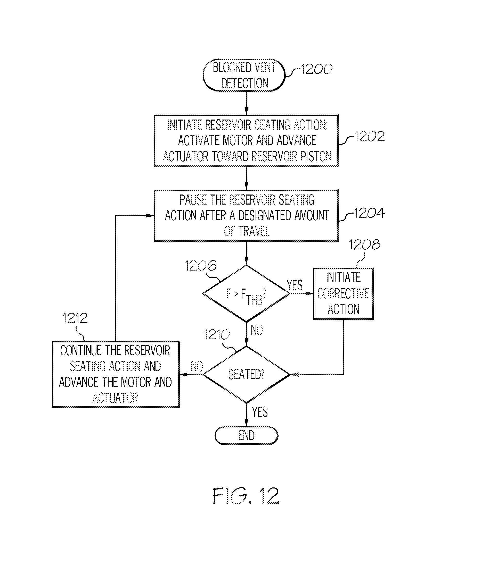
D00013

XML
uspto.report is an independent third-party trademark research tool that is not affiliated, endorsed, or sponsored by the United States Patent and Trademark Office (USPTO) or any other governmental organization. The information provided by uspto.report is based on publicly available data at the time of writing and is intended for informational purposes only.
While we strive to provide accurate and up-to-date information, we do not guarantee the accuracy, completeness, reliability, or suitability of the information displayed on this site. The use of this site is at your own risk. Any reliance you place on such information is therefore strictly at your own risk.
All official trademark data, including owner information, should be verified by visiting the official USPTO website at www.uspto.gov. This site is not intended to replace professional legal advice and should not be used as a substitute for consulting with a legal professional who is knowledgeable about trademark law.