Gear dynamic transmission error determination
Liu
U.S. patent number 10,274,399 [Application Number 15/319,228] was granted by the patent office on 2019-04-30 for gear dynamic transmission error determination. This patent grant is currently assigned to YANCHENG INSTITUTE OF TECHNOLOGY. The grantee listed for this patent is YANCHENG INSTITUTE OF TECHNOLOGY. Invention is credited to Fuhao Liu.


View All Diagrams
| United States Patent | 10,274,399 |
| Liu | April 30, 2019 |
Gear dynamic transmission error determination
Abstract
Determining a gear dynamic transmission error may include calculating a collision time interval via parameter values, such as an angular velocity of an input shaft measured by an angle coder, a drag torque of an output shaft provided by a magnetic powder brake, a gear backlash, and angular displacements of the input shaft and the output shaft and comparing a relative displacement contained with the gear backlash, until a value of the relative displacement of the comparison falls within an appropriate interval and meets requirements. In this way, a transmission error with relatively high accuracy may be obtained.
| Inventors: | Liu; Fuhao (Yancheng, CN) | ||||||||||
|---|---|---|---|---|---|---|---|---|---|---|---|
| Applicant: |
|
||||||||||
| Assignee: | YANCHENG INSTITUTE OF
TECHNOLOGY (Yancheng, CN) |
||||||||||
| Family ID: | 52943516 | ||||||||||
| Appl. No.: | 15/319,228 | ||||||||||
| Filed: | January 5, 2016 | ||||||||||
| PCT Filed: | January 05, 2016 | ||||||||||
| PCT No.: | PCT/CN2016/070104 | ||||||||||
| 371(c)(1),(2),(4) Date: | December 15, 2016 | ||||||||||
| PCT Pub. No.: | WO2016/110236 | ||||||||||
| PCT Pub. Date: | July 14, 2016 |
Prior Publication Data
| Document Identifier | Publication Date | |
|---|---|---|
| US 20170138819 A1 | May 18, 2017 | |
Foreign Application Priority Data
| Jan 5, 2015 [CN] | 2015 1 0003696 | |||
| Current U.S. Class: | 1/1 |
| Current CPC Class: | G01M 13/02 (20130101); G01M 13/021 (20130101) |
| Current International Class: | G01M 13/02 (20190101) |
| Field of Search: | ;73/115.01,115.02,115.06 |
| 101246083 | Aug 2008 | CN | |||
| 101271038 | Sep 2008 | CN | |||
| 102519723 | Jun 2012 | CN | |||
| 103698124 | Apr 2014 | CN | |||
| 104502096 | Apr 2015 | CN | |||
| H0933398 | Feb 1997 | JP | |||
Other References
|
International Search Report filed in PCT/CN2016/070104 dated Feb. 29, 2016. cited by applicant. |
Primary Examiner: McCall; Eric S.
Attorney, Agent or Firm: Rankin, Hill & Clark LLP
Claims
The invention claimed is:
1. A method for determining dynamic transmission error of gear, comprising: A. obtaining parameter values, the parameter values comprising an angular velocity of an input shaft measured by an angle coder and a drag torque of an output shaft provided by a magnetic powder brake, wherein the drag torque is T.sub.g=T.sub.m+T.sub.p cos(.omega.t); B. calculating a collision time interval .DELTA.t.sub.i between two gear teeth; C. comparing the collision time interval .DELTA.t.sub.i with a time-step .DELTA.t, and performing step D if .DELTA.t is less than .DELTA.t.sub.i; and performing step G if .DELTA.t is greater than or equal to .DELTA.t.sub.i, D. calculating a relative displacement of the gear x(n+1) by taking the time-step .DELTA.t as a step .DELTA.t. if an absolute value |x(n+1)| of the relative displacement x(n+1) is less than or equal to a gear backlash L, performing step J; and if the absolute value |x(n+1)| of the relative displacement x(n+1) is greater than the gear backlash L, decreasing the time-step .DELTA.t and then performing step E; E. comparing the time-step .DELTA.t with a minimum time-step t.sub.min, performing step D if the time-step .DELTA.t is greater than or equal to the minimum time length t.sub.min; and performing step F if the time-step .DELTA.t is less than the minimum time-step t.sub.min; F. calculating a relative displacement x(n+1)=L sign({dot over (x)}(t(n))) by taking the minimum time-step t.sub.min as a step, {dot over (x)}(n+1)=0, and then performing step J; G. calculating the relative displacement x(n+1) by taking the collision time interval .DELTA.t.sub.i as the step, if an absolute value |x(n+1)| of the relative displacement x(n+1) is less than or equal to L-.epsilon., performing step J; if the absolute value |x(n+1)| of the relative displacement x(n+1) is less than or equal to L+.epsilon. and the absolute value |x(n+1)| of the relative displacement x(n+1) is greater than L-.epsilon., performing step I; and if the absolute value |x(n+1)| of the relative displacement is greater than L+.epsilon., decreasing the collision time interval .DELTA.t.sub.i, and then performing step H; H. comparing the collision time interval .DELTA.t.sub.i with the minimum time-step t.sub.min, if the collision time interval .DELTA.t.sub.i is greater than or equal to the minimum time-step, returning to step G; if the collision time interval .DELTA.t.sub.i is less than the minimum time-step t.sub.min, taking the minimum time-step as the step t(n+1)=t(n)+t.sub.min, and then performing step I; I. calculating the relative displacement x(n+1)=L sign({dot over (x)}(t(n))), increasing the number of the step n by 1, then taking a collision time constant .di-elect cons..sub..DELTA.t as a step t(n+1)=t(n)+.di-elect cons..sub..DELTA.t, calculating a relative velocity as: {dot over (x)}(n+1)=-e{dot over (x)}(n), calculating the relative displacement as: x(n+1)=x(n), and then performing step J; and J. judging whether t(n+1) is greater than M.times.T.sub.f, if yes, finishing calculation, and if not, increasing the number of step n by 1 and then returning to step B; .epsilon. being a minimum error, M being a number of the period, T.sub.f being a period of the excitation, t(n) being a t(n).sup.(th) time sampling point, and x(n) being an n.sup.(th) relative displacement.
2. The method for determining dynamic transmission error of gear according to claim 1, wherein calculation of the collision time interval in step B is performed as follows: .DELTA..times..times..+-..times..times..times..times. ##EQU00007## wherein, a=(R.sub.bgT.sub.m+R.sub.bgT.sub.p cos(.omega.t.sub.0)-R.sub.bgkx(t.sub.0)-R.sub.bgc{dot over (x)}(t.sub.0))/2, b={dot over (x)}(t.sub.0), c=x(t.sub.0)-L sign({dot over (x)}(t.sub.0)), .DELTA.t.sub.i is a minimum positive real value of two values, R.sub.bg is a base radius of a driven wheel, R.sub.bp is a base radius of a driving wheel, T.sub.m is a ratio of a mean value of an external load moment and a rotational inertia of the driven wheel, T.sub.p is a ratio of a fluctuation portion of the external load moment and the rotational inertia of the driven wheel, .omega. is a frequency of the external load moment, t.sub.0 is an initial system time, k is a ratio of meshing stiffness of contacted front and side of a gear pair caused by an oil film and the rotational inertia of the driven wheel, and c is a ratio of meshing damping of the contacted front and side of the gear pair caused by the oil film and the rotational inertia of the driven wheel.
3. The method for determining dynamic transmission error of gear according to claim 1, directly performing step G if .DELTA.t.sub.i has no positive real value while calculating the collision time interval .DELTA.t.sub.i.
4. The method for determining dynamic transmission error of gear according to claim 1, wherein a specific operation of decreasing the time-step in step D decreases .DELTA.t.sup.2 from .DELTA.t.
5. The method for determining dynamic transmission error of gear according to claim 1, wherein a specific operation of decreasing the collision time interval in step D decreases .DELTA.t.sub.i.sup.2 from .DELTA.t.sub.i.DELTA.t.sub.i.sup.2.
Description
TECHNICAL FIELD
The present invention relates to the field of machine manufacturing and controlling, and more particularly, to a method for determining a dynamic transmission error of a gear, while considering a gear backlash.
BACKGROUND
In all mechanical drive, gear transmission has characteristics of steady drive, accuracy of drive ratio, high efficiency, long service life or the like, so that the gear transmission becomes the most important and widely used mechanism transmission High speed steady and precise gear transmission is a national key scientific and technological project. A transmission error has been widely accepted and considered as an excitation source for vibration and noise of a gear system because the transmission error affects force and velocity changes in the gear transmission. At the same time, the gear dynamic transmission error is also a very important part in gear testing, so that accurate testing and calculation of the transmission error are of great significance to gear manufacturing and the researches on gear dynamics.
The State Intellectual Property Office of the People's Republic of China disclosed a patent documentation on 1 Oct. 2008, with a Publication Patent No. of CN101275881, and titled Small Mode Number Gear transmission Error Measuring Method, including the steps of firstly connecting a measured gear, a driver, a first goniometric coder, a first shaft joint and a first electric motor in successive, then connecting a measuring gear, a flexible shaft joint, a second goniometric coder, a second shaft joint and a second electric motor in successive, the measured gear and the measuring being meshed in a single side and being driven by the two electric motors respectively, detecting an angular displacement .PHI.2 of the measuring gear relative to the second goniometric coder, an angular displacement .PHI.1 of a measuring gear shaft system and an angular displacement .PHI.' of a measured gear shaft system, and obtaining a transmission error of a small mode number gear after calculation. However, due to gear machining errors, installation errors, lubrication, modification and other factors, an offset of a tooth profile surface relative to an ideal tooth profile position will lead to a gear backlash (FIG. 1), so that positions of a meshing-in point and a meshing-out point will deviate from a theoretical meshing point when the gear is meshed in or meshed out, to produce corner meshing and cause a collision impact between meshing gear surfaces. Such collision impact plays a key role in smoothness and accuracy of high-speed gear transmission. For accuracy drive, trace idle stroke and impact occur during positive and reverse rotating, which affect the drive accuracy. Obviously, the gear backlash directly affects a gear system to obtain the transmission error. However, the influence of the gear backlash on the transmission error is not considered in this solution, so that a larger deviation will occur between a final calculation result and an actual value.
At the same time, the numerical calculation of the transmission error of the gear system becomes an increasingly prominent problem. At present, transmission error calculation methods stay in the traditional methods, such as: a Newmark integral method, a Runge-Kutta integral method, a Gear method and an improved Gear method (Wstiff method and Dstiff method). The above calculation methods have different emphasis on the transmission error calculation methods. Some methods focus more on grasping the calculation accuracy; while some methods have a faster calculation velocity. The traditional calculation methods usually fail to control the distribution of calculation time and calculation accuracy perfectly, often bring an enormous calculation quantity in case that the accuracy requirement is higher, resulting in a long calculation time; and will decrease the calculation accuracy in case of guaranteeing the calculation time, so that the transmission error of the gear system cannot be described and forecasted correctly.
SUMMARY
The present invention mainly solves a technical problem of the prior art that a transmission error is measured inaccurately due to a gear backlash during actual measurement, and a problem of it being difficult to balance a calculation accuracy and a calculation time by calculating a gear dynamic transmission error through theoretical simulation. Under the premise of taking the influence of the gear backlash on the transmission error into consideration, a calculation method that combines the actual measurement with the theoretical simulation and can quickly calculate the gear dynamic transmission error in a case of guaranteeing certain calculation accuracy is proposed.
The above technical problems are mainly solved by the present invention through the following technical solutions: a method for determining dynamic transmission error of gear includes the following steps of:
A. obtaining parameter values, the parameter values including an angular velocity of an input shaft measured by an angle coder and a drag torque of an output shaft provided by a magnetic powder brake;
B. calculating a collision time interval .DELTA.t.sub.i between two gear teeth;
C. comparing the collision time interval .DELTA.t.sub.i with a time-step .DELTA.t, performing step D if .DELTA.t is less than .DELTA.t.sub.i; and performing step G if .DELTA.t is greater than or equal to .DELTA.t.sub.i;
D. calculating a relative displacement of gear x(n+1) by taking the time-step .DELTA.t as a step, if an absolute value |x(n+1)| of the relative displacement x(n+1) is less than or equal to a gear backlash L, performing step J; and if the absolute value |x(n+1)| of the relative displacement x(n+1) is greater than the gear backlash L, decreasing the time-step .DELTA.t and then performing step E. comparing the time-step .DELTA.t with a minimum time-step t.sub.min, performing step D if the time-step .DELTA.t is greater than or equal to the minimum time length t.sub.min; and performing step F if the time-step .DELTA.t is less than the minimum time-step t.sub.min;
F. calculating a relative displacement t.sub.min by taking the minimum time-step x(n+1)=L sign({dot over (x)}(t(n))) as a step, {dot over (x)}(n+1)=0, and then performing step J;
G. calculating the relative displacement x(n+1) by taking the collision time interval .DELTA.t.sub.i as the step, if an absolute value |x(n+1)| of the relative displacement x(n+1) is less than or equal to L-.epsilon., performing step J; if the absolute value |x(n+1)| of the relative displacement x(n+1) is less than or equal to L+.epsilon. and the absolute value |x(n+1)| of the relative displacement x(n+1) is greater than L-.epsilon., performing step I; and if the absolute value |x(n+1)| of the relative displacement is greater than L+.epsilon., decreasing the collision time interval .DELTA.t.sub.i, and then performing step H;
H. comparing the collision time interval .DELTA.t.sub.i with the minimum time-step t.sub.min, if the collision time interval .DELTA.t.sub.i is greater than or equal to the minimum time-step, returning to step G; if the collision time interval .DELTA.t.sub.i is less than the minimum time-step t.sub.min, taking the minimum time-step as the step, i.e., t(n+1)=t(n)+t.sub.min, and then performing step I;
I. calculating the relative displacement x(n+1)=L sign({dot over (x)}(t(n))), increasing the number of the step n by 1, then taking a collision time constant .di-elect cons..sub..DELTA.t as a step, i.e., t(n+1)=t(n)+.di-elect cons..sub..DELTA.t, calculating a relative velocity as: {dot over (x)}(n+1)=-e{dot over (x)}(n), calculating the relative displacement as: x(n+1)=x(n), and then performing step J; and
J. judging whether tx(n+1) is greater than M.times.T.sub.f, if yes, finishing calculation, and if not, increasing the number of step n by 1 and then returning to step B;
.epsilon. being a minimum error, M is a number of the period, T.sub.f being a period of the excitation, t(n) being a t(n).sup.(th) time sampling point, and x(n) being an n.sup.(th) relative displacement, if an original point being located above a sign, it representing a derivation for time, one original point representing a first-order derivative, two original points representing second-order derivative, and sign being a sign function. The relative displacement of gear x(n+1), relative velocity {dot over (x)}(n+1) and time tx(n+1) of the M periods finally obtained can reflect the gear dynamic transmission error preferably. Through the transmission error obtained, the accuracy of a gearbox may be evaluated.
When measuring the actual gear set, various parameter values are measured in a conventional manner or set by a user, during analogue simulation calculation, the parameter values are manually set or automatically set by a computer. The parameter values include L, .epsilon., T.sub.f, R.sub.bg, R.sub.bp, .theta..sub.g, .theta..sub.p, the mean value of the external load moment, the rotational inertia of the driven wheel, the fluctuation portion of the external load moment, .omega., t.sub.0, the meshing stiffness at the front and lateral sides of the gear pair caused by the oil film, and the meshing damping at the front and lateral sides of the gear pair caused by the oil film, or the like.
Preferably, calculation of the collision time interval in step B is performed as follows:
.DELTA..times..times..+-..times..times..times..times. ##EQU00001##
wherein, a=(R.sub.bgT.sub.m+R.sub.bgT.sub.p cos(.omega.t.sub.g)-R.sub.bgkx(t.sub.0)-R.sub.bgc{dot over (x)}(t.sub.0))/2, b={dot over (x)}(t.sub.g), c=x(t.sub.0)-L sign({dot over (x)}(t.sub.0)), .DELTA.t.sub.i is a minimum positive real value of two values, R.sub.bg is a base radius of a driven wheel, R.sub.bp is a base radius of a driving wheel, T.sub.m is a ratio of a mean value of an external load moment to a rotational inertia of the driven wheel, T.sub.p is a ratio of a fluctuation portion of the external load moment to the rotational inertia of the driven wheel, .omega. is a frequency of the external load moment, t.sub.0 is an initial system time, k is a ratio of a sum of meshing stiffness at front and lateral contact sides of a gear pair caused by an oil film to the rotational inertia of the driven wheel, and c is a ratio of a sum of meshing damping at the front and lateral contact sides of the gear pair caused by the oil film to the rotational inertia of the driven wheel.
Preferably, .DELTA.t.sub.i<.DELTA.t is directly judged so that step G performed (i.e., the performing step G if .DELTA.t is greater than or equal to .DELTA.t.sub.i described in step C) if .DELTA.t.sub.i has no positive real value while calculating the collision time interval .DELTA.t.sub.i.
Preferably, a specific operation of decreasing the time-step in step D is decreased .DELTA.t.sup.2 from .DELTA.t.
Preferably, a specific operation of decreasing the collision time interval in step D is decreased .DELTA.t.sub.1.sup.2 from .DELTA.t.sub.i.
Substantial effects brought by the present invention are that the influence of the gear backlash on the transmission error is considered, and the calculation time is reduced as much as possible in the case of guaranteeing certain calculation accuracy, so that more preferable distribution of the calculation accuracy and calculation time is realized.
BRIEF DESCRIPTION OF THE DRAWINGS
FIG. 1 is an enlarged drawing of a gear meshing area of the present invention;
FIG. 2 is a schematic diagram of a parameter measurement system of the present invention;
FIG. 3 is a schematic diagram of assembling a driving wheel and a driven wheel according to a standard center distance of the present invention;
FIG. 4 is a schematic diagram of a judgment situation when the driving wheel is adhered to and linked with the driven wheel of the present invention;
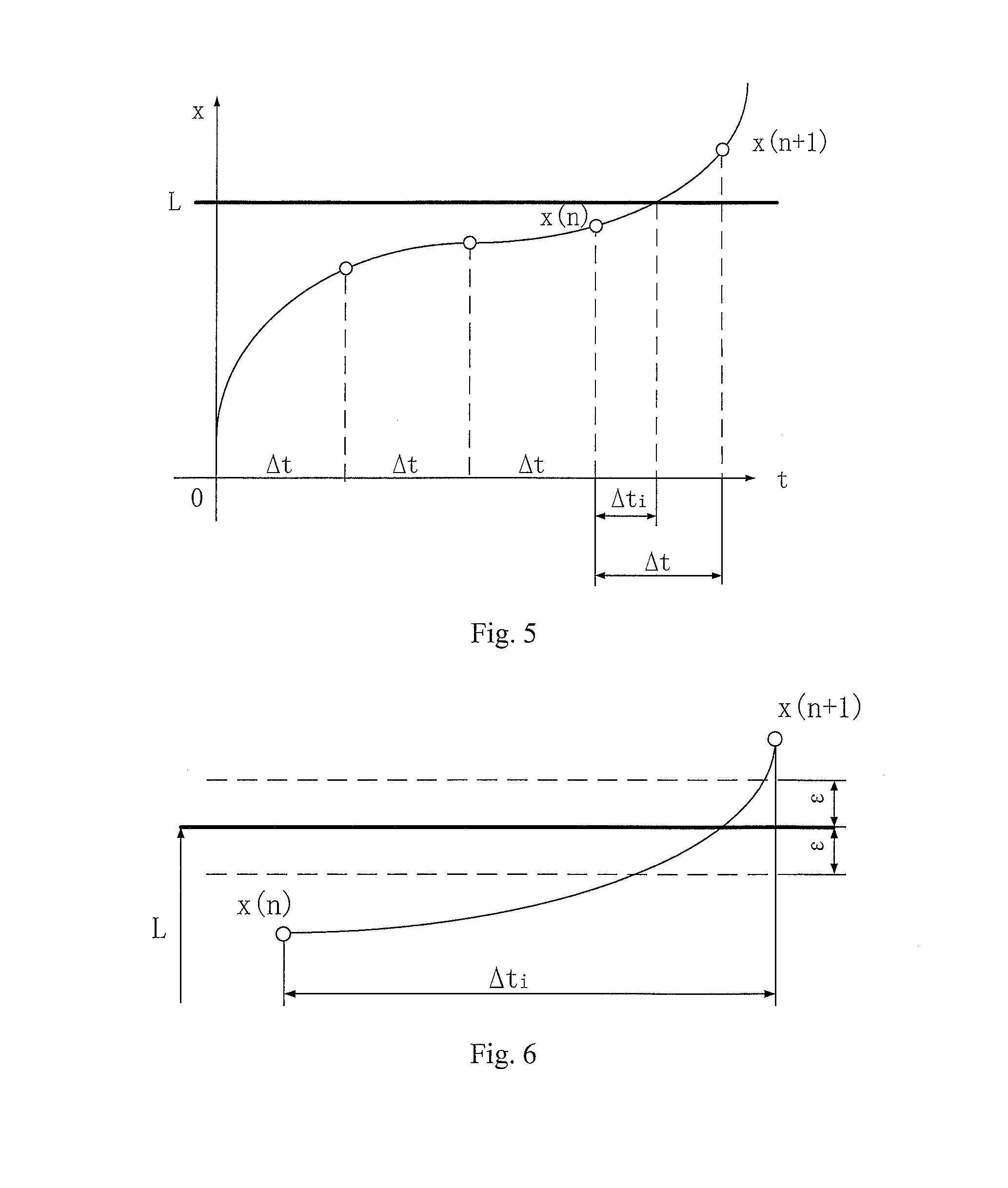
FIG. 5 is a schematic diagram of a situation when .DELTA.t.gtoreq..DELTA.t.sub.i during collision between teeth of the present invention;
FIG. 6 is a schematic diagram of a situation of using .epsilon. to make the collision between gear teeth precise again according to the present invention; and
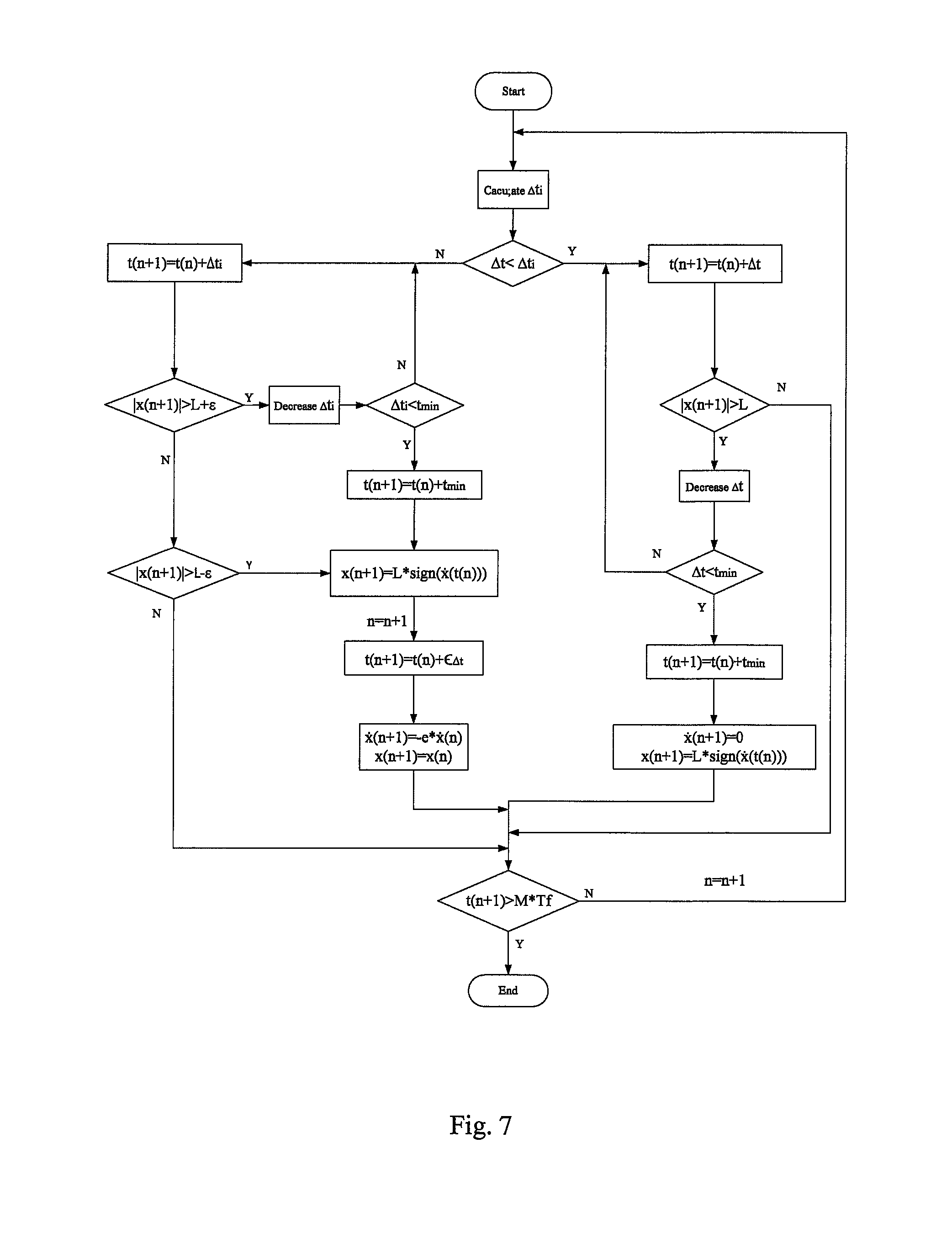
FIG. 7 is a flow chart of a determination method of the present invention;
in figures: 1 refers to electric motor, 2 refers to pinion gear; 3 refers to input shaft; 4 refers to angle coder; 5 refers to large gear; 6 refers to output shaft; and 7 refers to magnetic powder brake.
DETAILED DESCRIPTION
The technical solutions of the present invention will be further described hereinafter with reference to the embodiments and the drawings.
Embodiment: FIG. 2 is a system for measuring an actual gear set, which includes a motor 1, a driving gear 2, an input shaft 3, an angular coder 4, a driven wheel 5, an output shaft 6 and a magnetic powder brake 7. The driving wheel 2 and the driven wheel 5 are assembled according to a standard center distance, as shown in FIG. 3.
FIG. 1 is an enlarged drawing of a gear meshing area.
A transmission error (relative displacement) of a gear is a difference value between a position of a tooth profile on the driven wheel measured along a direction of a meshing line and related to drive characteristics during actual meshing and a position where the tooth profile should be located under an ideal condition, which may be defined as follows: x(t)=R.sub.bp.theta..sub.p(t)-R.sub.bg.theta..sub.g(t) (1)
wherein, R.sub.bg is a base radius of the driven wheel, R.sub.bp is a base radius of the driving wheel, .theta..sub.g is an angular displacement of the driven wheel, .theta..sub.p is an angular displacement of the driving wheel, and the angular displacement may also be measured by the angular coder.
Angular coder: measuring the angular velocity {dot over (.theta.)}.sub.p of the input shall in FIG. 2;
Magnetic powder brake: providing a drag torque for the output shaft, wherein the drag torque is: T.sub.g=T.sub.m+T.sub.p cos(.omega.t) (2)
wherein, T.sub.m and T.sub.p are the mean value of the external load moment and the moment of the fluctuation portion respectively; .omega. is a frequency of the drag torque.
When |x(t)|<L, a dynamic equation of the gear system is established according to the Alembert principle: I.sub.g{umlaut over (.theta.)}.sub.g(t)-(c.sub.1+c.sub.2){dot over (x)}(t)-(k.sub.1+k.sub.2)x(t)=-T.sub.g (3)
wherein, I.sub.g is a rotational inertia of a large gear; k.sub.1 and c.sub.1 are meshing stiffness and meshing damping at the front contact side of the gear pair caused by the oil film respectively; and T.sub.m and T.sub.p are the mean value of the external load moment and the moment of the fluctuation portion respectively. Both sides of the Formula (3) are divided by the rotational inertia I.sub.g at the same time to obtain: {umlaut over (.theta.)}.sub.g(t)-e{dot over (x)}(t)=-T.sub.m-T.sub.p cos(.omega.t) (4)
Here, c=(c.sub.1+c.sub.2)/I.sub.g, k=(k.sub.1+k.sub.2)/I.sub.g, T.sub.m=T.sub.m/I.sub.g and T.sub.p=T.sub.p/I.sub.g.
According to formula (4), it can be obtained: {umlaut over (.theta.)}.sub.x(t)=c{dot over (x)}(t)+kx(t)-T.sub.m-T.sub.p cos(.omega.t) (5)
From time t.sub.0 to time t, the angular velocity and the angular displacement of the big gear wheel may be obtained by performing integral on the formula (5).
.theta..function..theta..function..function..times..function..omega..time- s..times..function..omega..times..times..omega..function..function..functi- on..function..function..times..function..times..theta..function..theta..fu- nction..theta..function..times..times..times..function..omega..times..time- s..function..omega..times..times..omega..times..function..omega..times..ti- mes..omega..times..function..times..times..times..function..times..times..- times..function..times..theta..function..theta..function..theta..function.- .times. ##EQU00002##
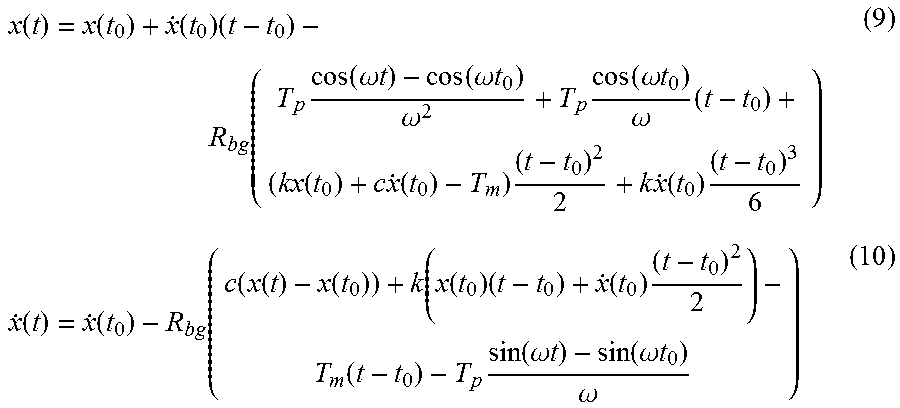
The formula (7) and the formula (8) are substituted into the formula (1) to obtain:
.function..function..function..times..function..times..function..omega..t- imes..times..function..omega..times..times..omega..times..function..omega.- .times..times..omega..times..function..times..times..function..times..time- s..times..function..times..function..function..function..function..functio- n..function..function..function..times..function..times..function..times..- function..omega..times..times..function..omega..times..times..omega. ##EQU00003##
When |x(t)|=L, an elastic collision occurs to the gear system, and the dynamic equation of the system at this moment is: x(t+.di-elect cons..sub..DELTA.t)=x(t)'{dot over (x)}(t+.di-elect cons..sub..DELTA.t)=-e{dot over (x)}(t) (11)
wherein, e is a collision coefficient, and a collision time constant .di-elect cons..sub..DELTA.t is an extremely small positive number. During collision, the transmission error may be represented as: x(t.sub.0+.DELTA.t.sub.i)=L sign({dot over (x)}(t.sub.0)) (12)
Here, .DELTA.t.sub.i=t.sub.i-t.sub.0 is a collision time interval; if sign({dot over (x)}(t.sub.0))>0, it represents that the collision occurs to the front side of the gear tooth, at this moment, the driven wheel rotates under the driving of the driving wheel. If sign({dot over (x)}(t.sub.0))<0, it represents that the collision occurs on the lateral side of the gear tooth, at this moment, the driving wheel rotates under the driving of the driven wheel.
The formula (9) is combined with the formula (12) to obtain:
.function..function..function..function..times..DELTA..times..times..func- tion..times..function..omega..times..times..function..omega..times..times.- .omega..times..function..omega..times..times..omega..times..DELTA..times..- times..function..times..times..function..times..DELTA..times..times..times- ..times..function..times..DELTA..times..times. ##EQU00004##
A second-order Taylor expansion is conducted near the small quantity of .DELTA.t.sub.i on left and right sides of the formula (13) at the same time, and an infinitely small quantity having an order higher than .DELTA.t.sub.i.sup.2 is ignored, to obtain:
.function..function..apprxeq..function..function..times..DELTA..times..ti- mes..times..function..times..times..function..times..function..omega..time- s..times..times..DELTA..times..times. ##EQU00005##
The following may be determined according to the above formula:
.DELTA..times..times..+-..times..times..times..times. ##EQU00006##
wherein, a=(R.sub.bgT.sub.m+R.sub.bgT.sub.p cos(.omega.t.sub.0)-R.sub.bgkx(t.sub.0)-R.sub.bgct(t.sub.0))/2, b={dot over (x)}(t.sub.0) and c=x(t.sub.0)-L sign({dot over (x)}(t.sub.0)). Only a minimal positive real value of .DELTA.t.sub.i is taken according to a physical significance. If .DELTA.t.sub.i has no minimal positive real value, it is deemed that .DELTA.t<.DELTA.t.sub.i.
As shown in FIG. 7, .DELTA.t.sub.i is compared with .DELTA.t to determine next time-step, if .DELTA.t<.DELTA.t.sub.i, then the relative displacement x(n+1) is calculated by the time-step .DELTA.t. If |x(n+1)|<L, the time .DELTA.t.sub.i of the next moment is calculated. If |x(n+1)|>L, it indicates that the relative displacement is greater than the gear backlash, and the time-step .DELTA.t shall be reduced according to formula .DELTA.t=.DELTA.t-.DELTA.t.sup.2 (16).
If the shortened time-step is greater than the minimum time-step t.sub.min set by the system according to the formula (16), then the relative displacement x(n+1) is recalculated. Otherwise, the minimum time-step t.sub.min is taken as a step by the system to calculate the relative displacement x(n+1). At this moment, the large gear and the pinion gear of the system are adhered and linked (as shown in FIG. 4). At this moment, it may be defined according to the physical significance thereof as follows: x(n+1)=L sign({dot over (x)})(t(n)))'{dot over (x)}(n+1)=0 (17)
If .DELTA.t.gtoreq..DELTA.t.sub.i (as shown in FIG. 5), then .DELTA.t.sub.i is served as the next step to calculate a next relative displacement and velocity. Similarly, x(n+1) needs to be judged, if |x(n+1)|>L+.epsilon., it proves that the relative displacement x(n+1) herein goes beyond an accuracy range, as shown in FIG. 6, and .DELTA.t.sub.i needs to be decreased here, so as to guarantee the accuracy within an allowable error range, and a formula of decreasing .DELTA.t.sub.i as as follows: .DELTA.t.sub.i=.DELTA.t.sub.i-.DELTA.t.sub.i.sup.2 (18)
.DELTA.t.sub.i in the formula (18) is the step, to recalculate x(n+1) and {dot over (x)}(n+1). if |x(n+1)|>L+.epsilon. at this moment, the formula (18) is repeated until .DELTA.t.sub.i<t.sub.min, then t.sub.min is taken as a step by the system to calculate the relative displacement and the relative velocity. At this moment, a collision occurs to the system, and according to the actual physical significance of collision, set: x(n+1)=L sign({dot over (x)}(t(n)))' (19)
In order to guarantee that the relative displacement values of the system before and after collision are equal, a small quantity of time is introduced herein, i.e., a collision time constant .di-elect cons..sub..DELTA.t, so that .di-elect cons..sub..DELTA.t is taken as a step by the system, i.e.,: t(n+1)=t(n)+.di-elect cons..sub..DELTA.t (20)
The relative displacement and the relative velocity are recalculated, and the relative displacement and relative velocity after the collision are as follows: {dot over (x)}(n+1)=-e{dot over (x)}(n), x(n+1)=x(n) (21)
If the formula |x(n+1)|>L+.epsilon. is not satisfied, but |x(n+1)|>L-.epsilon. is satisfied, a collision occurs to the system, and formulas (19), (20), and (21) are repeated at this moment.
If neither |x(n+1)|>L+.epsilon. nor |x(n+1)|>L-.epsilon. is satisfied, it illustrates that no collision occurs to the system, and the displacement and the velocity are recalculated at this moment.
Through continuous circulation in such a way, a large number of x(n+1), {dot over (x)}(n+1), t(n+1) and other data may be recorded. During the entire course of operation, if t(n+1)<M*T.sub.f, then the relative displacement and relative velocity obtained are substituted into the formula (15) to recalculate .DELTA.t.sub.i. If t(n+1)>M*T.sub.f, then the operation is stopped, thus being capable of obtaining the relative displacement (transmission error), the relative velocity (velocity of transmission error) and the time data of M periods. M is a number of the period of the excitation, T.sub.f is a period of the excitation, and the excitation is provided by the magnetic powder brake.
In conclusion, according to the method for determining dynamic transmission error of gear of the present invention, the collision time interval is calculated via the parameter values such as the angular velocity of the input shaft 3 measured by the angle coder 4, the drag torque of the output shaft 6 provided by the magnetic powder brake 7, the gear backlash, and angular displacements of the input shaft 3 and the output shaft 6; and the relative displacement obtained is compared with the gear backlash, until the value of the relative displacement falls within an appropriate interval and meets requirements, the result obtained being namely the transmission error with relatively high accuracy. By considering the influence of the gear backlash on the transmission error, the accuracy of a transmission error determination result is guaranteed, meanwhile, the accuracy and time are also well balanced, and the method is applicable to the measurement, calculation and analogue simulation calculation of an actual gear set.
The specific embodiments described herein merely illustrate the spirit of the present invention. Those killed in the art may figure out various modifications or supplements or replacements in a similar mode on the specific embodiments described without departing from the spirit of the invention or going beyond the scope defined by the claims appended.
Although such terms as relative displacement and collision time interval are frequently used herein, this does not exclude the possibility of using other terms. These terms are merely used for describing and explaining the essence of the present invention more conveniently; and explaining the terms into any additional limitation departs from the spirit of the present invention.
* * * * *
D00000
D00001
D00002
D00003
D00004
M00001
M00002
M00003
M00004
M00005
M00006
M00007
XML
uspto.report is an independent third-party trademark research tool that is not affiliated, endorsed, or sponsored by the United States Patent and Trademark Office (USPTO) or any other governmental organization. The information provided by uspto.report is based on publicly available data at the time of writing and is intended for informational purposes only.
While we strive to provide accurate and up-to-date information, we do not guarantee the accuracy, completeness, reliability, or suitability of the information displayed on this site. The use of this site is at your own risk. Any reliance you place on such information is therefore strictly at your own risk.
All official trademark data, including owner information, should be verified by visiting the official USPTO website at www.uspto.gov. This site is not intended to replace professional legal advice and should not be used as a substitute for consulting with a legal professional who is knowledgeable about trademark law.