Rotor for gas turbine engine
Maalouf , et al.
U.S. patent number 10,273,972 [Application Number 14/944,303] was granted by the patent office on 2019-04-30 for rotor for gas turbine engine. This patent grant is currently assigned to UNITED TECHNOLOGIES CORPORATION. The grantee listed for this patent is United Technologies Corporation. Invention is credited to Michael Espinoza, Eliannah Hunderfund, Fadi S. Maalouf, Steven M. Modon, Christopher L. Potter.


| United States Patent | 10,273,972 |
| Maalouf , et al. | April 30, 2019 |
Rotor for gas turbine engine
Abstract
A rotating component for a turbine engine includes a main component portion including a web and a platform located at a radially outboard portion of the web, relative to an axis of rotation of the rotating component. A snap surface is located at the platform and is configured to interlock the rotating component with an adjacent rotating component. A transition surface extends from the main component portion to the snap surface and includes two or more different radii.
| Inventors: | Maalouf; Fadi S. (East Hampton, CT), Potter; Christopher L. (East Hampton, CT), Espinoza; Michael (Middletown, CT), Hunderfund; Eliannah (Hartford, CT), Modon; Steven M. (Portland, CT) | ||||||||||
|---|---|---|---|---|---|---|---|---|---|---|---|
| Applicant: |
|
||||||||||
| Assignee: | UNITED TECHNOLOGIES CORPORATION
(Farmington, CT) |
||||||||||
| Family ID: | 57348561 | ||||||||||
| Appl. No.: | 14/944,303 | ||||||||||
| Filed: | November 18, 2015 |
Prior Publication Data
| Document Identifier | Publication Date | |
|---|---|---|
| US 20170138368 A1 | May 18, 2017 | |
| Current U.S. Class: | 1/1 |
| Current CPC Class: | F02C 3/04 (20130101); F04D 29/324 (20130101); F04D 19/02 (20130101); F01D 5/066 (20130101); F05D 2260/941 (20130101); F05D 2220/32 (20130101); F05D 2260/30 (20130101); F05D 2300/50212 (20130101); F05D 2230/642 (20130101); F05D 2250/712 (20130101); F05D 2240/30 (20130101); F05D 2240/80 (20130101); F05D 2230/10 (20130101) |
| Current International Class: | F04D 29/32 (20060101); F02C 3/04 (20060101); F04D 19/02 (20060101); F01D 5/06 (20060101) |
References Cited [Referenced By]
U.S. Patent Documents
| 5220784 | June 1993 | Wilcox |
| 5435694 | July 1995 | Kray |
| 5537814 | July 1996 | Nastuk |
| 6267553 | July 2001 | Burge |
| 7186079 | March 2007 | Suciu |
| 8459943 | June 2013 | Schutte |
| 9909595 | March 2018 | Colletti |
| 2006/0099070 | May 2006 | Suciu |
| 2006/0099078 | May 2006 | Rice |
| 2008/0181779 | July 2008 | Decardenas |
| 2011/0064580 | March 2011 | Barnes |
| 2012/0027606 | February 2012 | Malmborg |
| 2013/0259659 | October 2013 | Knaul |
| 2014160215 | Oct 2014 | WO | |||
| 2015023860 | Feb 2015 | WO | |||
Other References
|
European Search Report and Written Opinion; European Application No. 16199525.3; International Filing Date: Nov. 18, 2016; dated Apr. 29, 2017; 7 pages. cited by applicant. |
Primary Examiner: McCalister; William M
Attorney, Agent or Firm: Cantor Colburn LLP
Claims
The invention claimed is:
1. A rotating component for a turbine engine comprising: a main component portion including: a web; and a platform disposed at a radially outboard portion of the web, relative to an axis of rotation of the rotating component; a radially inboard platform surface defining a snap diameter thereat, the radially inboard platform surface disposed at the platform and configured to interlock the rotating component with an adjacent rotating component at an adjacent rotating component surface radially inboard of the radially inboard platform surface; and a transition surface extending from the main component portion to the radially inboard platform surface including two or more different radii, the transition surface including: a first radius of the two or more different radii extending radially outwardly from the web to a transition point; and a second radius of the two or more different radii extending from the transition point to the radially inboard platform surface; wherein the transition point is radially outboard of the radially inboard platform surface.
2. The rotating component of claim 1, wherein the first radius is larger than the second radius.
3. The rotating component of claim 1, wherein the transition surface includes: a first radius extending from the platform to a transition point; and a second radius extending from the transition point to the radially inboard platform surface.
4. A compressor rotor for a gas turbine engine comprising: a plurality of rotor blades; a main rotor portion supporting of the plurality of rotor blades, the main rotor portion including: a radially-extending web portion; and a platform portion affixed to the web portion and supportive of the plurality of rotor blades; a radially inboard platform surface defining a snap diameter thereat, the radially inboard platform surface disposed at the platform portion and configured to interlock the compressor rotor with an adjacent rotating component at an adjacent rotating component surface radially inboard of the radially inboard platform surface; and a transition surface extending from the main component portion to the radially inboard platform surface including two or more different radii, the transition surface including: a first radius of the two or more different radii extending radially outwardly from the web to a transition point; and a second radius of the two or more different radii extending from the transition point to the radially inboard platform surface; wherein the transition point is radially outboard of the radially inboard platform surface.
5. The compressor rotor of claim 4, wherein the first radius is larger than the second radius.
6. The compressor rotor of claim 5, wherein the first radius is about two times the second radius.
7. The compressor rotor of claim 4, wherein the transition surface includes: a first radius extending from the platform to a transition point; and a second radius extending from the transition point to the radially inboard platform surface.
8. The compressor rotor of claim 4, wherein the adjacent rotating component is one of an adjacent compressor rotor or a compressor spacer.
9. The compressor rotor of claim 4, wherein the radially inboard platform surface defines an interference fit between the compressor rotor and the adjacent rotating component.
10. A gas turbine engine comprising: a turbine section; a combustor section to provide combustion gases to the turbine section; and a compressor section to compress an airflow and direct the compressed airflow toward the combustor, the compressor section including a compressor rotor having: a plurality of rotor blades; a main rotor portion supporting of the plurality of rotor blades, the main rotor portion including: a radially-extending web portion; and a platform portion affixed to the web portion and supportive of the plurality of rotor blades; a radially inboard platform surface defining a snap diameter thereat, the radially inboard platform surface disposed at the platform portion and configured to interlock the compressor rotor with an adjacent rotating component at an adjacent rotating component surface radially inboard of the radially inboard platform surface; and a transition surface extending from the main component portion to the radially inboard platform surface including two or more different radii, the transition surface including: a first radius of the two or more different radii extending radially outwardly from the web to a transition point; and a second radius of the two or more different radii extending from the transition point to the radially inboard platform surface; wherein the transition point is radially outboard of the radially inboard platform surface.
11. The gas turbine engine of claim 10, wherein the first radius is larger than the second radius.
12. The gas turbine engine of claim 11, wherein the first radius is about two times the second radius.
13. The gas turbine engine of claim 10, wherein the transition surface includes: a first radius extending from the platform to a transition point; and a second radius extending from the transition point to the radially inboard platform surface.
14. The gas turbine engine of claim 10, wherein the adjacent rotating component is one of an adjacent compressor rotor or a compressor spacer.
Description
BACKGROUND
This disclosure relates to gas turbine engines, and more particularly to rotating components of gas turbine engines.
Gas turbine engines, such as those used to power modern commercial and military aircrafts, generally include a compressor section to pressurize an airflow, a combustor section for burning hydrocarbon fuel in the presence of the pressurized air, and a turbine section to extract energy from the resultant combustion gases. The airflow flows along a gaspath through the gas turbine engine.
The gas turbine engine includes a plurality of rotors arranged along an axis of rotation of the gas turbine engine, in both the compressor section and the turbine section. Some of these rotors are connected to axially adjacent rotors, spacers, or other rotating components, via interference fit, also known in the art as a "snap fit". The rotor in general, and the snap flange of the rotor in particular can be a highly stressed area during operation of the gas turbine aircraft. It is desired to reduce stresses in this area to prolong the service life of the rotor.
SUMMARY
In one embodiment, a rotating component for a turbine engine includes a main component portion including a web and a platform located at a radially outboard portion of the web, relative to an axis of rotation of the rotating component. A snap surface is located at the platform and is configured to interlock the rotating component with an adjacent rotating component. A transition surface extends from the main component portion to the snap surface and includes two or more different radii.
Additionally or alternatively, in this or other embodiments the transition surface includes a first radius extending from the web to a transition point and a second radius extending from the transition point to the snap surface.
Additionally or alternatively, in this or other embodiments the first radius is larger than the second radius.
Additionally or alternatively, in this or other embodiments the transition point is radially outboard of the snap surface.
Additionally or alternatively, in this or other embodiments the transition surface includes a first radius extending from the platform to a transition point and a second radius extending from the transition point to the snap surface.
In another embodiment, a compressor rotor for a gas turbine engine includes a plurality of rotor blades and a main rotor portion supporting of the plurality of rotor blades. The main rotor portion includes a radially-extending web portion and a platform portion affixed to the web portion and supportive of the plurality of rotor blades. A snap surface is located at the platform portion and is configured to interlock the compressor rotor with an adjacent rotating component. A transition surface extends from the main rotor portion to the snap surface, the transition surface including two or more different radii.
Additionally or alternatively, in this or other embodiments the transition surface includes a first radius extending from the web to a transition point and a second radius extending from the transition point to the snap surface.
Additionally or alternatively, in this or other embodiments the first radius is larger than the second radius.
Additionally or alternatively, in this or other embodiments the first radius is about two times the second radius.
Additionally or alternatively, in this or other embodiments the transition point is radially outboard of the snap surface.
Additionally or alternatively, in this or other embodiments the transition surface includes a first radius extending from the platform to a transition point and a second radius extending from the transition point to the snap surface.
Additionally or alternatively, in this or other embodiments the adjacent rotating component is one of an adjacent compressor rotor or a compressor spacer.
Additionally or alternatively, in this or other embodiments the snap surface defines an interference fit between the compressor rotor and the adjacent rotating component.
In yet another embodiment, a gas turbine engine includes a turbine section, a combustor section to provide combustion gases to the turbine section, and a compressor section to compress an airflow and direct the compressed airflow toward the combustor. The compressor section includes a compressor rotor having a plurality of rotor blades and a main rotor portion supporting of the plurality of rotor blades. The main rotor portion includes a radially-extending web portion and a platform portion affixed to the web portion and supportive of the plurality of rotor blades. A snap surface is located at the platform portion and is configured to interlock the compressor rotor with an adjacent rotating component. A transition surface extends from the main rotor portion to the snap surface, the transition surface including two or more different radii.
Additionally or alternatively, in this or other embodiments the transition surface includes a first radius extending from the web to a transition point and a second radius extending from the transition point to the snap surface.
Additionally or alternatively, in this or other embodiments the first radius is larger than the second radius.
Additionally or alternatively, in this or other embodiments the first radius is about two times the second radius.
Additionally or alternatively, in this or other embodiments the transition point is radially outboard of the snap surface.
Additionally or alternatively, in this or other embodiments the transition surface includes a first radius extending from the platform to a transition point and a second radius extending from the transition point to the snap surface.
Additionally or alternatively, in this or other embodiments the adjacent rotating component is one of an adjacent compressor rotor or a compressor spacer.
BRIEF DESCRIPTION OF THE DRAWINGS
The subject matter which is regarded as the present disclosure is particularly pointed out and distinctly claimed in the claims at the conclusion of the specification. The foregoing and other features, and advantages of the present disclosure are apparent from the following detailed description taken in conjunction with the accompanying drawings in which:
FIG. 1 illustrates a schematic cross-sectional view of an embodiment of a gas turbine engine;
FIG. 2 illustrates a schematic cross-sectional view of an embodiment of a compressor of a gas turbine engine;
FIG. 3 illustrates a schematic cross-sectional view of another embodiment of a compressor of a gas turbine engine; and
FIG. 4 illustrates a schematic cross-sectional view of an embodiment of a compressor rotor for a gas turbine engine.
DETAILED DESCRIPTION
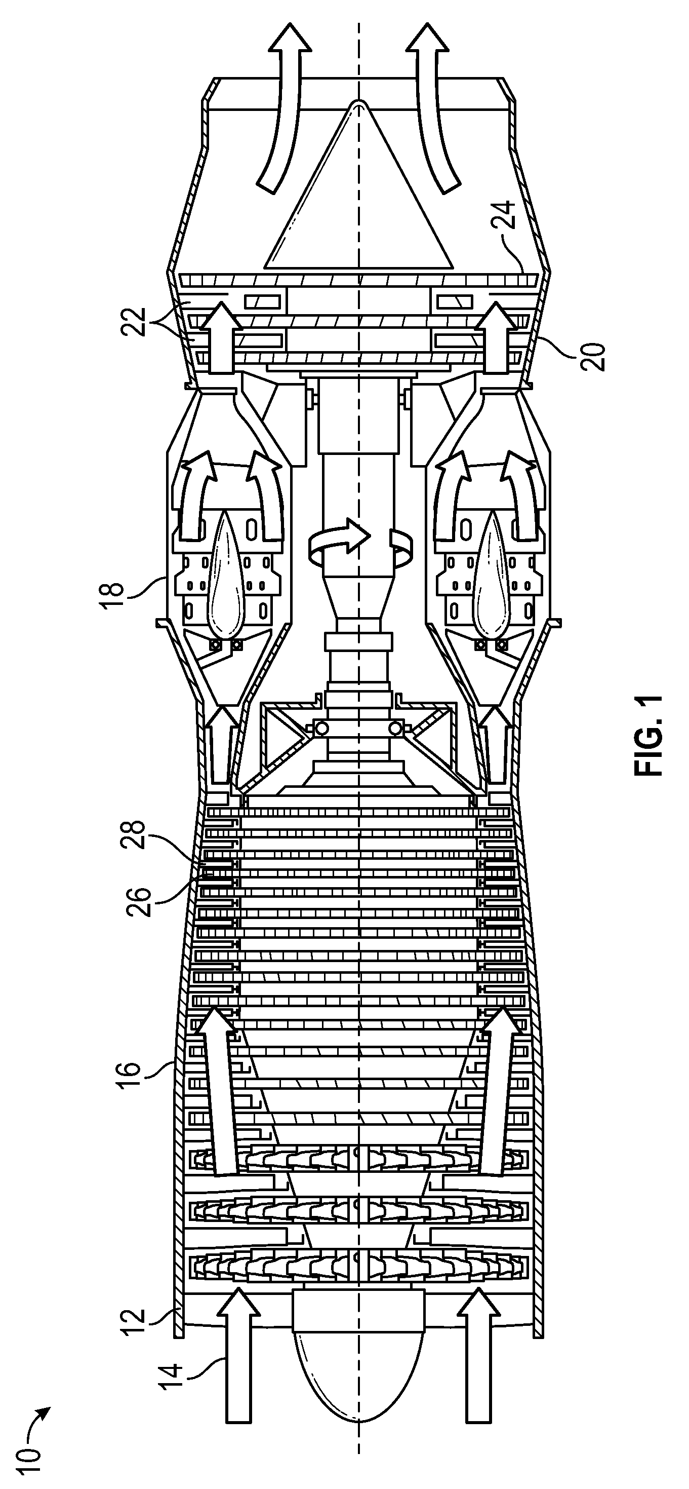
FIG. 1 is a schematic illustration of a gas turbine engine 10. The gas turbine engine generally has a fan 12 through which ambient air is propelled in the direction of arrow 14, a compressor 16 for pressurizing the air received from the fan 12 and a combustor 18 wherein the compressed air is mixed with fuel and ignited for generating combustion gases.
The gas turbine engine 10 further comprises a turbine section 20 for extracting energy from the combustion gases. Fuel is injected into the combustor 18 of the gas turbine engine 10 for mixing with the compressed air from the compressor 16 and ignition of the resultant mixture. The fan 12, compressor 16, combustor 18, and turbine 20 are typically all concentric about a common central longitudinal axis of the gas turbine engine 10. In some embodiments, the turbine 20 includes one or more turbine stators 22 and one or more turbine rotors 24. Likewise, the compressor 16 includes one or more compressor rotors 26 and one or more compressor stators 28. It is to be appreciated that while description below relates to compressors 16 and compressor rotors 26, one skilled in the art will readily appreciate that the present disclosure may utilized with respect to turbine rotors 24.
Referring now to FIG. 2, The compressor 16 includes a compressor case 30, in which the compressor rotors 26 are arranged along an engine axis 32 about which the compressor rotors 26 rotate. Each compressor rotor 26 includes a rotor disc 34 with a plurality of rotor blades 36 extending radially outwardly from the rotor disc 34. In some embodiments, the rotor disc 34 and the plurality of rotor blades 36 are a single, unitary structure, an integrally bladed compressor rotor 26. In other embodiments, the rotor blades 36 are each installed to the rotor disc 34 via, for example, a dovetail joint where a tab or protrusion at the rotor blade 36 is inserted into a corresponding slot in the rotor disc 34.
As shown in FIG. 2, axially adjacent compressor rotors 26 may be joined to each other, while in other embodiments, as shown in FIG. 3, the compressor rotor 26 may be joined to another rotating component, such as a spacer 38. The compressor rotor 26 is secured to the adjacent rotating component by an interference fit, which in some embodiments is combined with another mechanical fastening, such as a plurality of bolts (not shown) to secure the components.
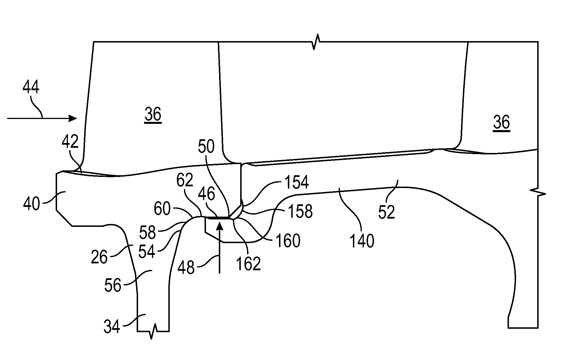
Referring now to FIG. 4, a more detailed view of the interference fit, also referred to as a "snap fit", between the compressor rotor 26 and the adjacent rotating component is shown. Compressor rotor 26, as stated above, includes a plurality of rotor blades 36 secured to, and radially extending from a rotor disc 34. In particular, the rotor blades 36 extend from a blade platform 40 portion of the rotor disc 34. The blade platform 40 extends in a substantially axial direction, and includes a flowpath surface 42 that defines an inner boundary of a flowpath 44 of the gas turbine engine 10. A radially inboard platform surface 46, opposite the flowpath surface 42 and radially inboard therefrom, defines a rotor snap diameter 48. The rotor snap diameter 48 interfaces with an adjacent component snap diameter 50 to join the compressor rotor 26 and the adjacent component 52.
In their respective free, unrestrained states, and when unjoined, the adjacent component snap diameter 50 is larger than the rotor snap diameter 48. To join the components, the compressor rotor 26 may heated and/or the adjacent component 52 may be cooled to temporarily enlarge the rotor snap diameter 48 and/or temporarily cool the adjacent component snap diameter 50, respectively. The components then may be joined, and when returned to ambient temperature the desired interference fit is achieved between the rotor snap diameter 48 and the adjacent component snap diameter 50.
The snap diameters 48, 50 are formed in the components by, for example, a grinding operation. The grinding operation is performed during manufacture after surface treatment of the compressor rotor 26 by, for example, shot peening. Any inadvertent damage to the peened surface during grinding requires the compressor rotor 26 to be retreated by shot peening. To reduce the risk of inadvertent damage to the compressor rotor 26, a transition area 54 between the rotor snap diameter 48 and a web 56 of the rotor disc 34 includes a compound radius. The web 56 extends from an inner radial extent of the rotor disc 34 to the blade platform 40.
The transition area 54 includes a first radius 58 extending from the web 56 to a transition point 60 radially outboard of the snap diameter 48. To minimize stresses and increase durability of the compressor rotor 26, the first radius 58 is selected to be as large as practicable. A second radius 62 extends from the transition point 60 to the rotor snap diameter 48 and is smaller than first radius 58. In some embodiments, the first radius 58 is about two times the second radius 62. Further, in some embodiments, the first radius 58 is between about 50 and about 0.100'', and in other embodiments the second radius 62 is between about 0.020'' and about 0.050''.
The transition area 54 including first radius 58 and second radius 62 is beneficial to the compressor rotor 26 and to the gas turbine engine 10 in several ways. The large first radius 58 reduces stresses on the compressor rotor 26 and improves durability of the compressor rotor 26. Further, the smaller second radius 62 allows for snap diameter 48 to have a larger axial width greater than a compressor rotor with a single-radius transition. Also, the use of a relatively small second radius 62 enables an increase in first radius 58 to lower compressor rotor stresses.
In some embodiments, adjacent component 52 includes a transition area 154. Similarly, the transition area 154 includes a first radius 158 extending from a platform 140 to a transition point 160 radially inboard of the adjacent component snap diameter 50. To minimize stresses and increase durability, the first radius 158 is selected to be as large as practicable. A second radius 162 extends from the transition point 160 to the adjacent component snap diameter 50 and is smaller than first radius 158. In some embodiments, the first radius 158 is about two times the second radius 162. Further, in some embodiments, the first radius 158 is between about 0.050'' and about 0.100'', and in other embodiments the second radius 162 is between about 0.020'' and about 0.050''.
While the present disclosure has been described in detail in connection with only a limited number of embodiments, it should be readily understood that the present disclosure is not limited to such disclosed embodiments. Rather, the present disclosure can be modified to incorporate any number of variations, alterations, substitutions or equivalent arrangements not heretofore described, but which are commensurate with the scope of the present disclosure. Additionally, while various embodiments of the present disclosure have been described, it is to be understood that aspects of the present disclosure may include only some of the described embodiments. Accordingly, the present disclosure is not to be seen as limited by the foregoing description, but is only limited by the scope of the appended claims.
* * * * *
D00000
D00001
D00002
D00003
XML
uspto.report is an independent third-party trademark research tool that is not affiliated, endorsed, or sponsored by the United States Patent and Trademark Office (USPTO) or any other governmental organization. The information provided by uspto.report is based on publicly available data at the time of writing and is intended for informational purposes only.
While we strive to provide accurate and up-to-date information, we do not guarantee the accuracy, completeness, reliability, or suitability of the information displayed on this site. The use of this site is at your own risk. Any reliance you place on such information is therefore strictly at your own risk.
All official trademark data, including owner information, should be verified by visiting the official USPTO website at www.uspto.gov. This site is not intended to replace professional legal advice and should not be used as a substitute for consulting with a legal professional who is knowledgeable about trademark law.