Key driven internal locking device for cabinet drawers
Chen , et al.
U.S. patent number 10,273,721 [Application Number 15/897,686] was granted by the patent office on 2019-04-30 for key driven internal locking device for cabinet drawers. This patent grant is currently assigned to E-MAKE Co., Ltd. The grantee listed for this patent is Kung-Cheng Chen, Lung-Chuan Huang. Invention is credited to Kung-Cheng Chen, Lung-Chuan Huang.
View All Diagrams
| United States Patent | 10,273,721 |
| Chen , et al. | April 30, 2019 |
Key driven internal locking device for cabinet drawers
Abstract
A cabinet includes drawers each having a rear latch; and a key driven internal locking device including a rod including a front key hole and a rear bent member; a longitudinal member secured to an inner surface of a rear end of the cabinet and including a longitudinal groove; a sliding member slidably disposed in the longitudinal groove and including rectangular openings on a front surface, a protrusion on a top of the sliding member, and an upper driven member secured to the front surface of the sliding member and having a through hole with the bent member passing through; fastening plates each secured to two sides of the longitudinal member wherein the uppermost fastening plate has a pivot hole with the rear end of the rod passing through into the longitudinal member; and a concave member in an upper portion of the longitudinal member.
| Inventors: | Chen; Kung-Cheng (Taichung, TW), Huang; Lung-Chuan (Taichung, TW) | ||||||||||
|---|---|---|---|---|---|---|---|---|---|---|---|
| Applicant: |
|
||||||||||
| Assignee: | E-MAKE Co., Ltd (Taichung,
TW) |
||||||||||
| Family ID: | 66248126 | ||||||||||
| Appl. No.: | 15/897,686 | ||||||||||
| Filed: | February 15, 2018 |
| Current U.S. Class: | 1/1 |
| Current CPC Class: | E05B 63/143 (20130101); E05B 65/462 (20130101); E05B 55/00 (20130101); E05B 65/463 (20130101) |
| Current International Class: | E05B 65/462 (20170101); E05B 55/00 (20060101); E05B 63/14 (20060101) |
| Field of Search: | ;70/78-88 ;292/DIG.18 ;312/216-219,221 |
References Cited [Referenced By]
U.S. Patent Documents
| 1613731 | January 1927 | Stockov |
| 1847106 | March 1932 | Turner |
| 3371974 | March 1968 | Vermeersch |
| 3622216 | November 1971 | Haunost |
| 5257860 | November 1993 | Slivon |
| 5782545 | July 1998 | Kahara |
| 5862689 | January 1999 | Wen |
| 6082839 | July 2000 | Chiku |
| 6347848 | February 2002 | Cho |
| 6637843 | October 2003 | Westwinkel |
| 6722167 | April 2004 | Hsu |
| 6742854 | June 2004 | Chen |
| 6896342 | May 2005 | Cheng |
| 7144092 | December 2006 | Chang |
| 7264319 | September 2007 | Cheng |
| 7784887 | August 2010 | Grela |
| 7891222 | February 2011 | Ratkus |
| 2005/0210933 | September 2005 | Wen |
| 2006/0138912 | June 2006 | Chen |
Claims
What is claimed is:
1. A cabinet comprising: a plurality of drawers each comprising two slides on outer surfaces of two sides respectively, and a latch disposed on an outer surface of a rear end and including an upper inclined surface, an upper projection in rear of the upper inclined surface, a lower inclined surface, an upper flat surface in front of the upper inclined surface, a lower flat surface in front of the lower inclined surface, and a shoulder between the lower inclined surface and the lower flat surface; and a key driven internal locking device comprising: a rod including a key hole on a front end, and a bent member adjacent to a rear end; a longitudinal member secured to an inner surface of a rear end of the cabinet and including a longitudinal groove; a sliding member slidably disposed in the longitudinal groove and including a plurality of rectangular openings on a front surface wherein a predetermined number of the rectangular openings correspond to the latches, a protrusion on a top of the sliding member, and an upper driven member secured to the front surface of the sliding member and having a through hole with the bent member passing through; a plurality of fastening plates each secured to two sides of the longitudinal member wherein an uppermost one of the fastening plates has a pivot hole with the rear end of the rod passing through into the longitudinal member; and a concave member fastened in an upper portion of the longitudinal member and above the protrusion; wherein in a locked state of the cabinet, the bent member projects upward, the protrusion is disposed in the concave member, each latch is inserted into the corresponding rectangular opening, each latch is blocked by an inner surface of the front surface of the sliding member, and all of the drawers are locked; wherein in response to inserting a key into the key hole and clockwise rotating the key, the rod clockwise rotates to push the driven member downward, the sliding member moves downward to clear the protrusion out of the concave member, the latches are not blocked by the inner surface of the front surface of the sliding member, and all of the drawers are unlocked; wherein in response to pulling out one drawer in one operation, the latch pushes the front surface of the sliding member upward to insert the protrusion into the concave member and the latches of the remaining drawers are blocked by the inner surface of the front surface of the sliding member, and the remaining drawers are locked; wherein in response to pulling out one drawer in one operation, the upper inclined surface of the latch pushes the front surface of the sliding member upward to insert the protrusion into the concave member and the shoulders of the latches of the remaining drawers are blocked by the inner surface of the front surface of the sliding member; and wherein in response to pulling out one drawer in one operation, all of the remaining drawers are locked and prior to pulling out a second drawer, one drawer is pushed in with the lower inclined surface of one drawer pushes down the sliding member so that the shoulders of the latches are not blocked by the inner surface of the front surface of the sliding member.
Description
BACKGROUND OF THE INVENTION
1. Field of the Invention
The invention relates to cabinet locks and more particularly to a locking device mounted on an inner surface of a back of a cabinet, the locking device being adapted to be locked or unlocked by inserting a key into a key hole of a rod rotatably secured to a sliding member and turning the key so that once the locking device is unlocked, one of drawers is allowed to open.
2. Description of Related Art
U.S. Pat. No. 6,742,854 to Chen discloses an anti-inclination and internal locking device for a cabinet comprising a cabinet body, at least two drawers disposed in the cabinet body, a projecting body disposed on rear side of each drawer, a base seat fixedly disposed on inner side of a rear wall board of the cabinet body corresponding to each drawer, a slide seat slidably fitted in the base seat and movable between a first position and a second position and a first and a second connecting sections respectively disposed at one end of the base seat and one end of the slide seat. The projecting body has an activating section and a stop section. The slide seat is formed with an opening corresponding to the projecting body. After one drawer is drawn out, the activating section of the projecting body of the drawn out drawer drives the slide seat and then the first connecting section is connected with the second connecting section to make the slide seat positioned in the first position, whereby the stop section of the projecting body of the other drawer is engaged with the corresponding opening.
While the patent enjoys its success in the market, continuing improvements in the exploitation of a key driven internal locking device for cabinet drawers are constantly being sought.
SUMMARY OF THE INVENTION
It is therefore one object of the invention to provide a cabinet comprising a plurality of drawers each comprising two slides on outer surfaces of two sides respectively, and a latch on an outer surface of a rear end; and a key driven internal locking device comprising a rod including a key hole on a front end, and a bent member adjacent to a rear end; a longitudinal member secured to an inner surface of a rear end of the cabinet and including a longitudinal groove; a sliding member slidably disposed in the longitudinal groove and including a plurality of rectangular openings on a front surface wherein a predetermined number of the rectangular openings correspond to the latches, a protrusion on a top of the sliding member, and an upper driven member secured to the front surface of the sliding member and having a through hole with the bent member passing through; a plurality of fastening plates each secured to two sides of the longitudinal member wherein an uppermost one of the fastening plates has a pivot hole with the rear end of the rod passing through into the longitudinal member; and a concave member fastened in an upper portion of the longitudinal member and above the protrusion; wherein in a locked state of the cabinet, the bent member projects upward, the protrusion is complementarily disposed in the concave member, each latch is inserted into the corresponding rectangular opening, each latch is blocked by an inner surface of the front surface of the sliding member, and all of the drawers are locked; wherein in response to inserting a key into the key hole and clockwise rotating the key, the rod clockwise rotates to push the driven member downward, the sliding member moves downward to clear the protrusion out of the concave member, the latches are not blocked by the inner surface of the front surface of the sliding member, and all of the drawers are unlocked; and wherein in response to pulling out one drawer, the latch pushes the front surface of the sliding member upward to insert the protrusion into the concave member and the latches of the remaining drawers are blocked by the inner surface of the front surface of the sliding member, and the remaining drawers are locked.
The above and other objects, features and advantages of the invention will become apparent from the following detailed description taken with the accompanying drawings.
BRIEF DESCRIPTION OF THE DRAWINGS
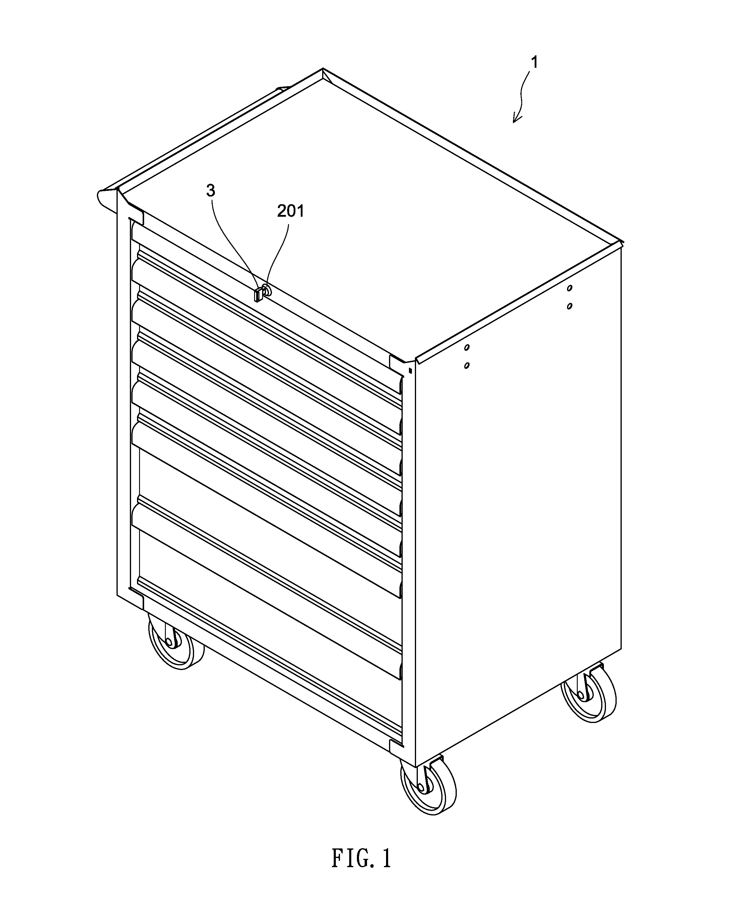
FIG. 1 is a perspective view of a wheeled cabinet incorporating a key driven locking device for drawers according to the invention;
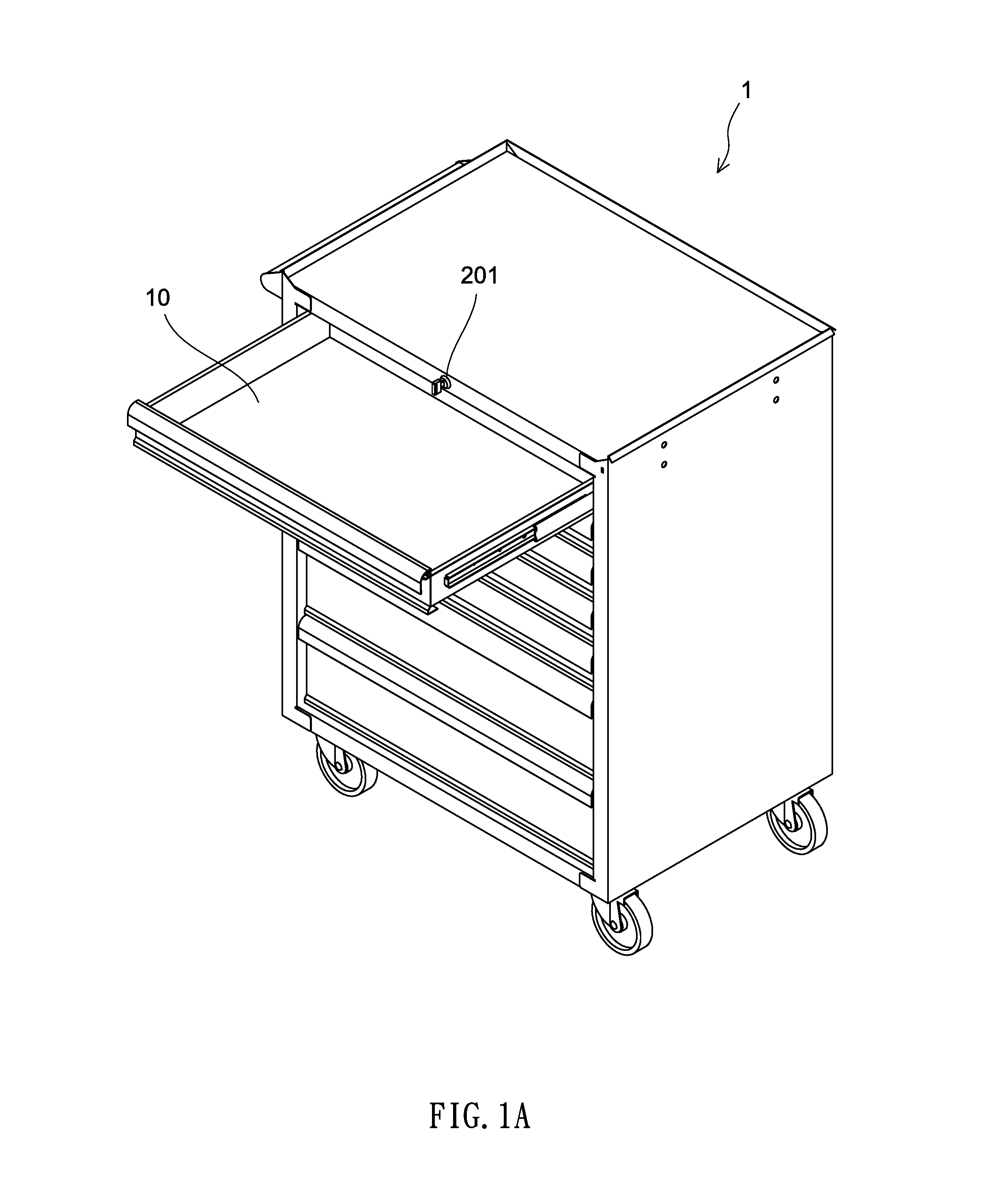
FIG. 1A is a view similar to FIG. 1 with a drawer drawn out;
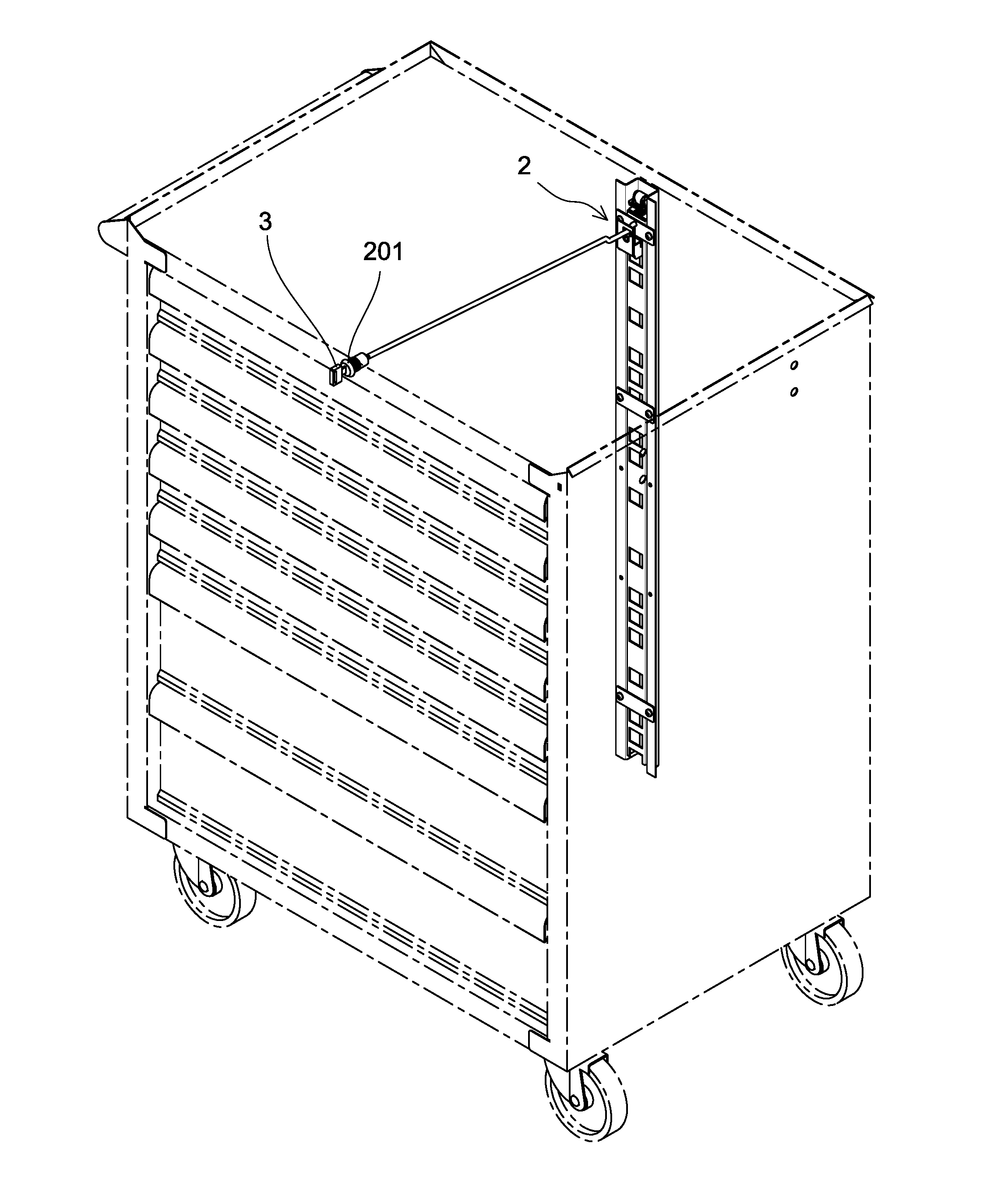
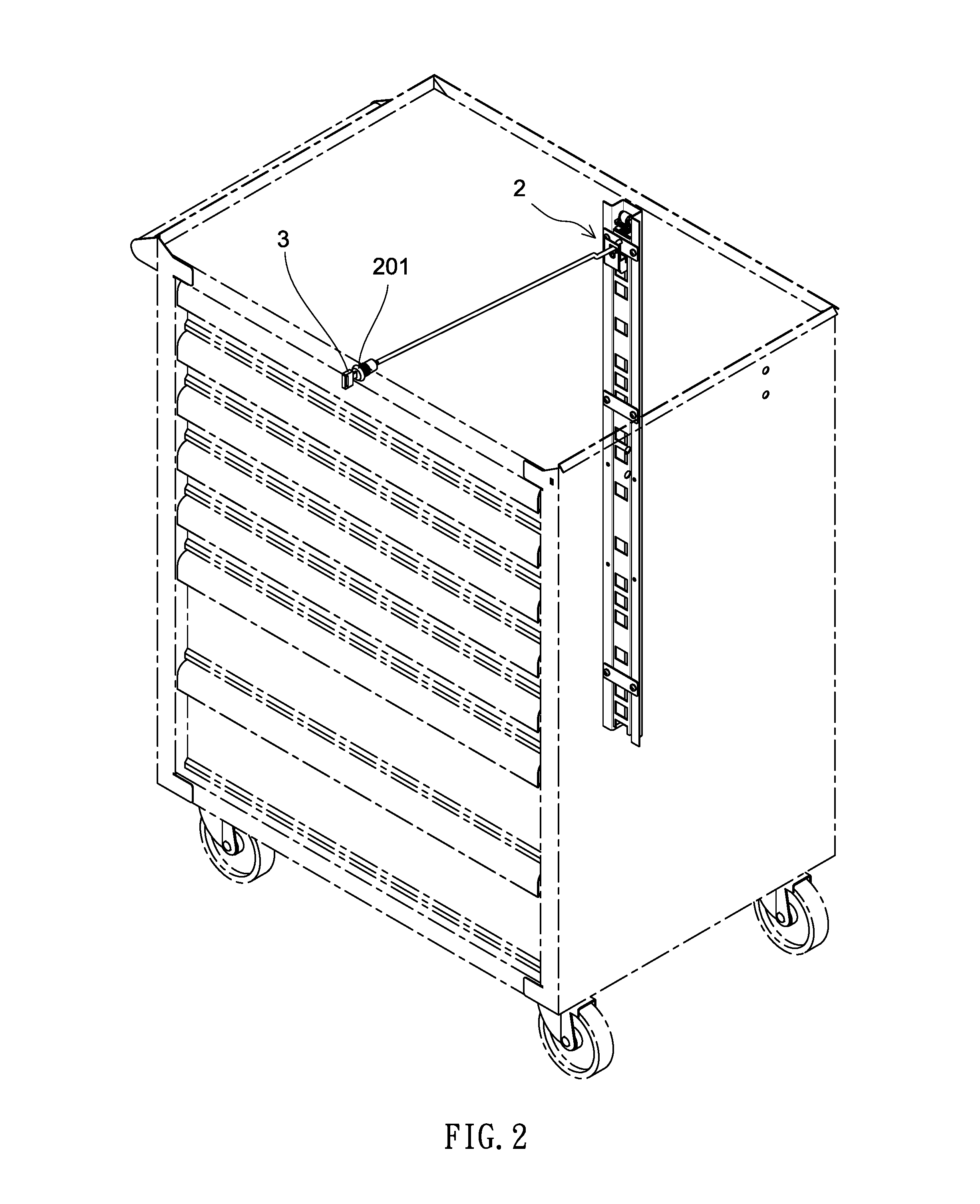
FIG. 2 is a view similar to FIG. 1 showing a key, a rod and other elements of the locking device in a transparent manner;
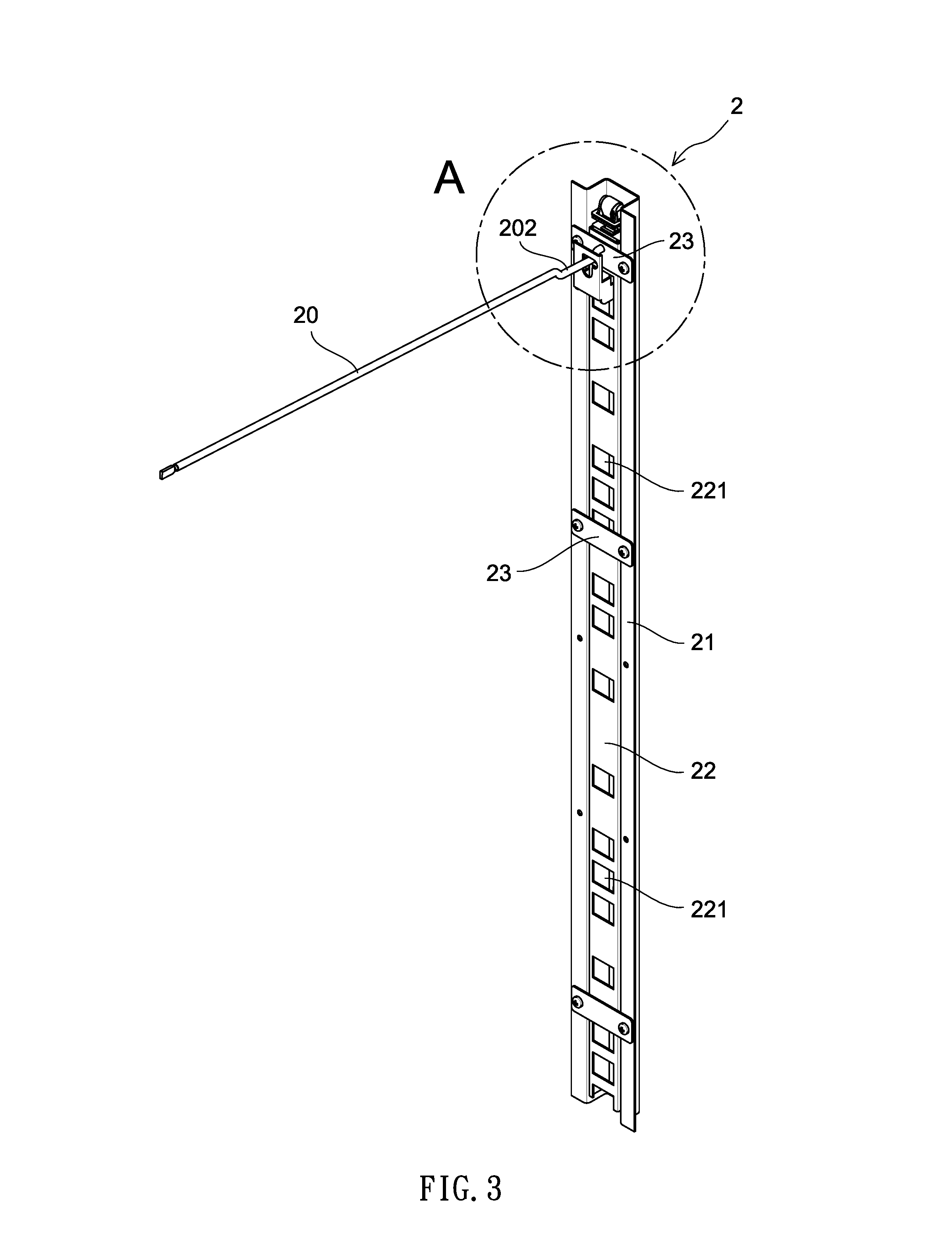
FIG. 3 is a perspective view of the locking device;
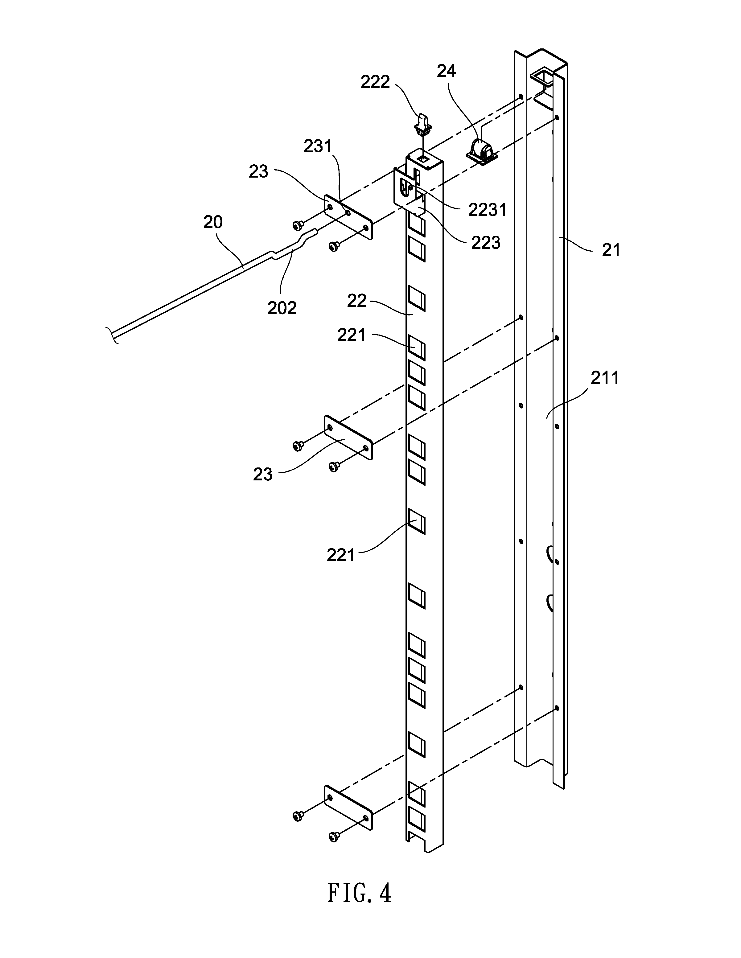
FIG. 4 is an exploded view of the locking device;
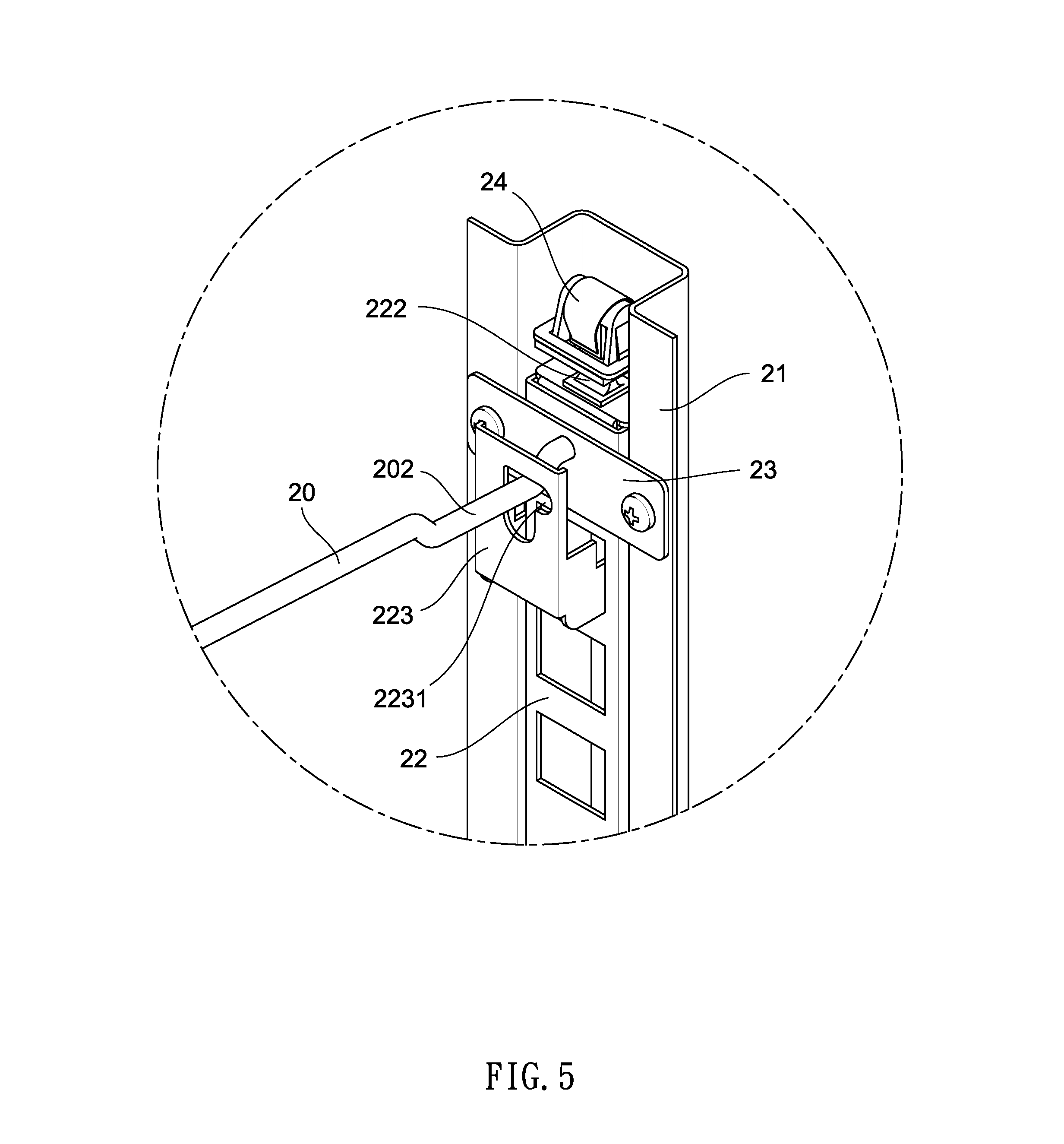
FIG. 5 is a detailed view of an area in circle A of FIG. 3, the locking device being unlocked;
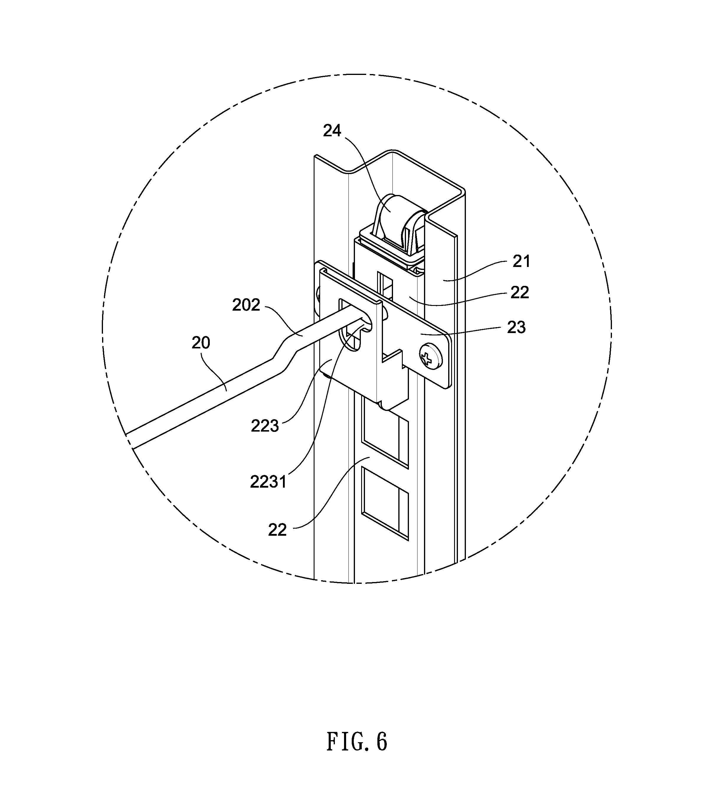
FIG. 6 is a view similar to FIG. 5, the locking device being locked;
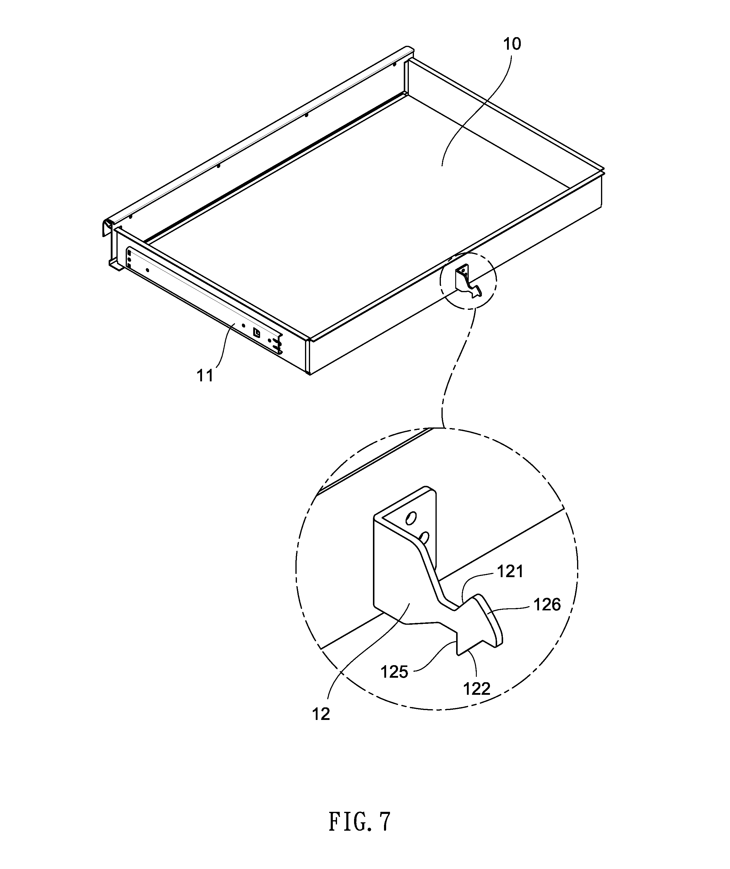
FIG. 7 is a perspective view of the drawer with a slide mounted on each of two sides thereof;
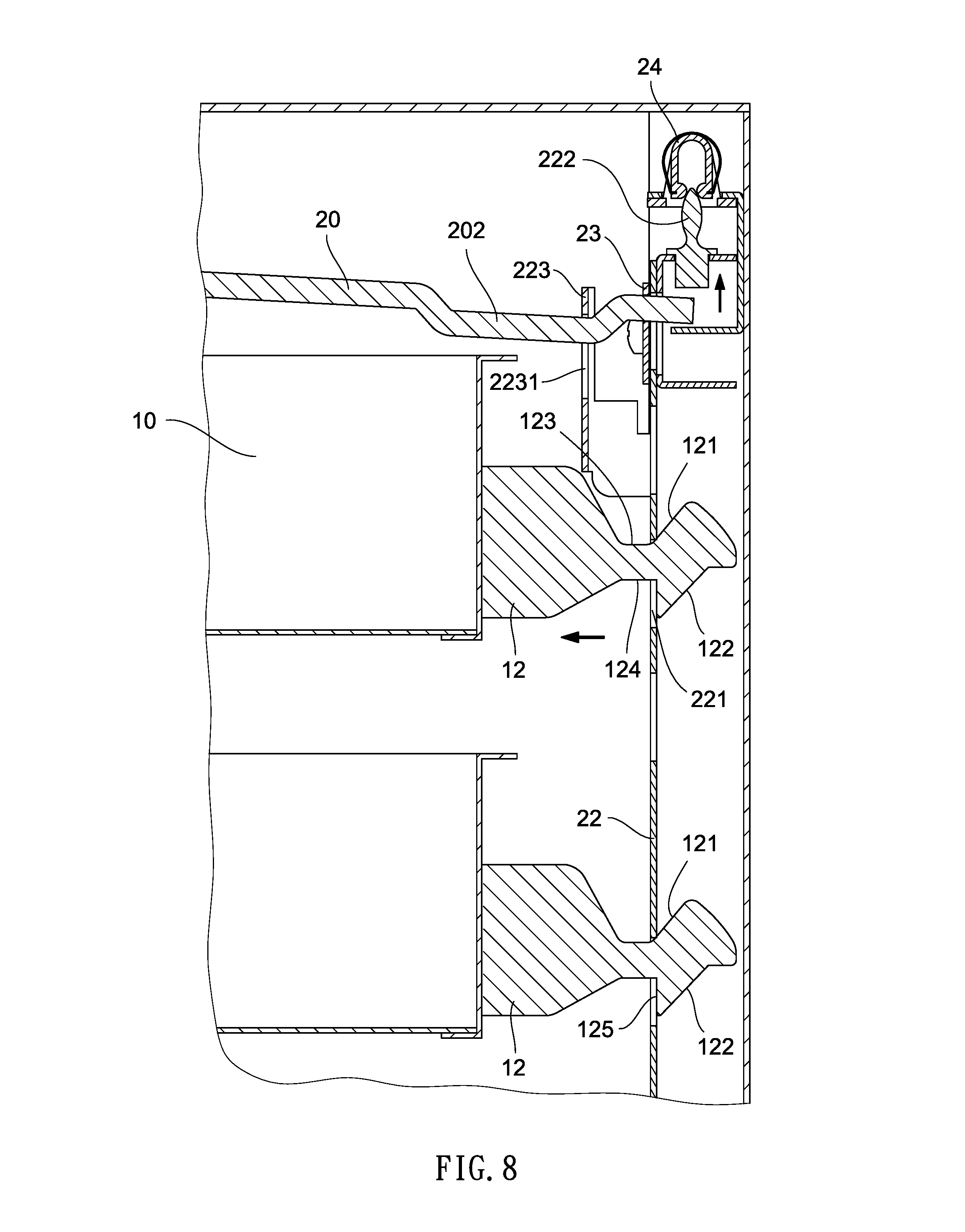
FIG. 8 is a longitudinal sectional view of FIG. 5;
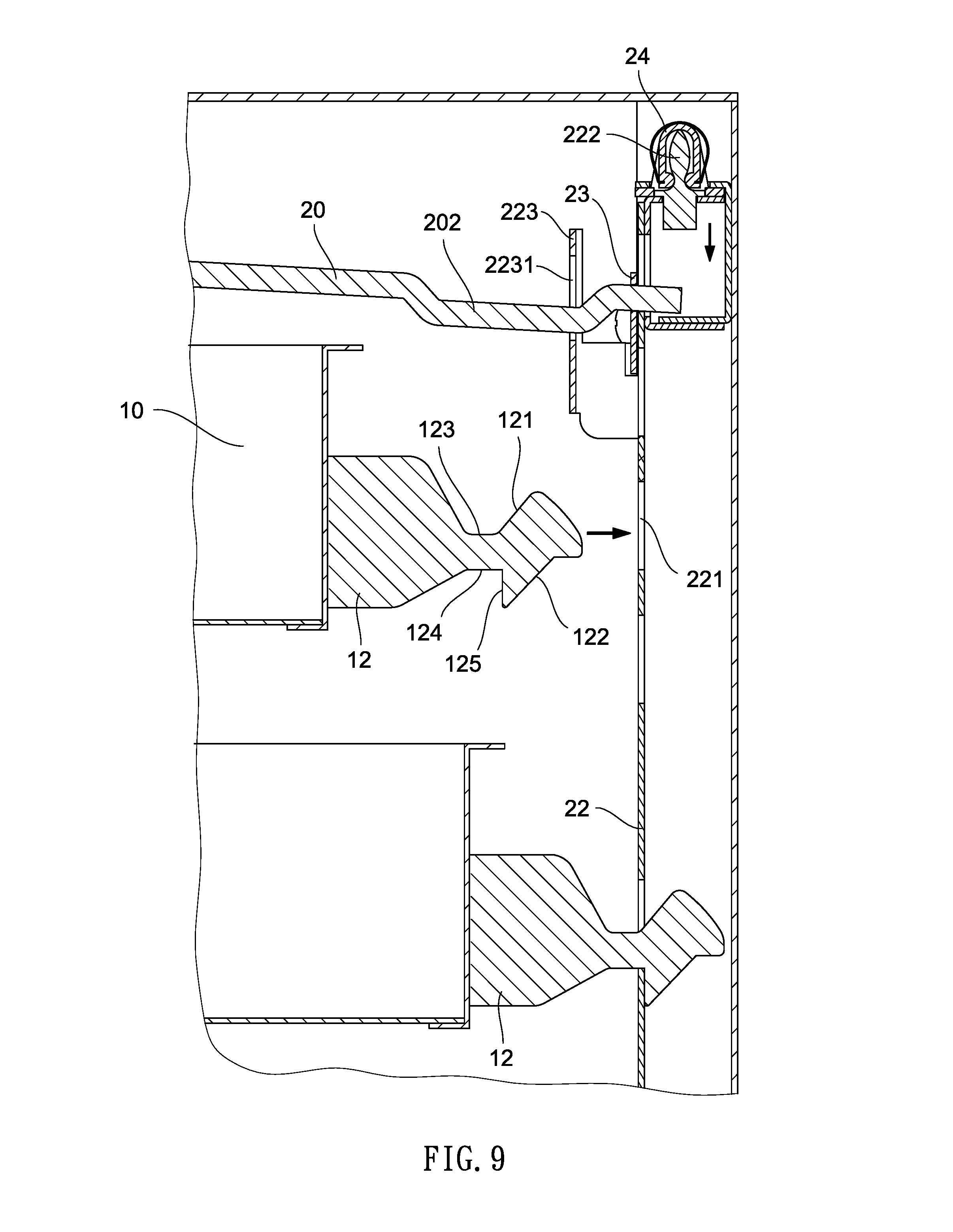
FIG. 9 is a longitudinal sectional view of FIG. 6; and
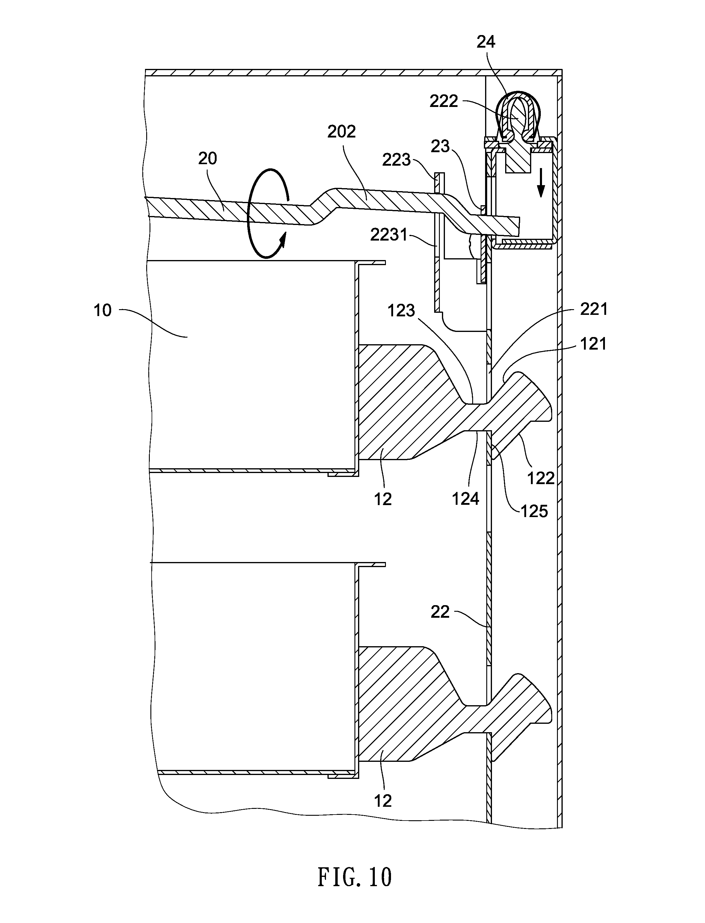
FIG. 10 is a view similar to FIG. 9, the topmost drawer being pushed in.
DETAILED DESCRIPTION OF THE INVENTION
Referring to FIGS. 1 to 10, a wheeled cabinet 1 incorporating a key driven internal locking device 2 in accordance with the invention is shown. The cabinet 1 comprises a plurality of drawers 10 each including two slides 11 on outer surfaces of two sides respectively, and a latch 12 on an outer surface of a rear end. The latch 12 includes an upper inclined surface 121, an upper projection 126 in rear of the upper inclined surface 121, a lower inclined surface 122, an upper flat surface 123 in front of the upper inclined surface 121, a lower flat surface 124 in front of the lower inclined surface 122, and a shoulder 125 between the lower inclined surface 122 and the lower flat surface 124.
The key driven internal locking device 2 comprises a rod 20 including a key hole 201 on a front end, and a bent member 202 adjacent to a rear end; a longitudinal member 21 secured to an inner surface of the rear end of the cabinet 1 and including a longitudinal groove 211; a hollow sliding member 22 slidably disposed in the groove 211 and including a plurality of rectangular openings 221 on a front surface in which some openings 221 correspond to the latches 12, a protrusion 222 on a top of the sliding member 22, and an upper driven member 223 secured to the front surface of the sliding member 22 and having a through hole 2231 with the bent member 202 passing through; a plurality of fastening plates 23 each secured to two sides of the longitudinal member 21 in which the uppermost fastening plate 23 has a pivot hole 231 with the rear end of the rod 20 passing through into the longitudinal member 21 to be positioned therein; and a concave member 24 fastened in an upper portion of the longitudinal member 21 and above the protrusion 222.
In a locked state of the cabinet 1, the bent member 202 projects upward, the protrusion 222 is complementarily disposed in the concave member 24, the latch 12 is inserted into the rectangular opening 221, and the shoulder 125 of the latch 12 is blocked by an inner surface of the front surface of the sliding member 22. Thus, all drawers 10 are locked.
A user may insert a key 3 into a key hole 201 and clockwise rotates the key 3. And in turn, the rod 20 clockwise rotates to push the driven member 223 downward. Also, the sliding member 22 moves downward to clear the protrusion 222 out of the concave member 24, and the shoulder 125 of the latch 12 is not blocked by the inner surface of the front surface of the sliding member 22. Thus, all drawers 10 are unlocked.
It is envisaged by the invention that only one drawer 10 can be pulled out in one operation. This is because when one drawer 10 is pulled out, the upper inclined surface 121 of the latch 12 pushes the front surface of the sliding member 22 upward to insert the protrusion 222 into the concave member 24 and the shoulders 125 of the latches 12 of the remaining drawers 10 are blocked by the inner surface of the front surface of the sliding member 22. Thus, all of the remaining drawers 10 are locked. This has the advantage of preventing all drawers 10 from being pulled out in one operation. Otherwise, the cabinet 1 may fall due to movement of the gravity thereof.
While the invention has been described in terms of preferred embodiments, those skilled in the art will recognize that the invention can be practiced with modifications within the spirit and scope of the appended claims.
* * * * *
D00000
D00001
D00002
D00003
D00004
D00005
D00006
D00007
D00008
D00009
D00010
D00011
XML
uspto.report is an independent third-party trademark research tool that is not affiliated, endorsed, or sponsored by the United States Patent and Trademark Office (USPTO) or any other governmental organization. The information provided by uspto.report is based on publicly available data at the time of writing and is intended for informational purposes only.
While we strive to provide accurate and up-to-date information, we do not guarantee the accuracy, completeness, reliability, or suitability of the information displayed on this site. The use of this site is at your own risk. Any reliance you place on such information is therefore strictly at your own risk.
All official trademark data, including owner information, should be verified by visiting the official USPTO website at www.uspto.gov. This site is not intended to replace professional legal advice and should not be used as a substitute for consulting with a legal professional who is knowledgeable about trademark law.