Dental prosthesis and method of its production utilizing standardized framework keys and matching premanufactured teeth
Balshi , et al.
U.S. patent number 10,271,929 [Application Number 15/390,330] was granted by the patent office on 2019-04-30 for dental prosthesis and method of its production utilizing standardized framework keys and matching premanufactured teeth. This patent grant is currently assigned to Global Dental Sciences, LLC. The grantee listed for this patent is Global Dental Science, LLC. Invention is credited to Stephen F. Balshi, Thomas J. Balshi.


View All Diagrams
| United States Patent | 10,271,929 |
| Balshi , et al. | April 30, 2019 |
Dental prosthesis and method of its production utilizing standardized framework keys and matching premanufactured teeth
Abstract
A system including a method and associated structures creates efficiencies in the manufacture of prosthetic tooth support frameworks. Pre-manufactured teeth with matching internal keys are used in the setup of a patient prototype. Each key includes a shaft, a cervical platform, a retention knob and preferably at least one channel for the expulsion of excess adhesive fluid. The cervical platforms are shaped to provide intimate contact with a base of their respective tooth. The same tooth/key pairs are then used to make a framework pattern from the setup positioning. The pattern can be cast or scanned for direct machining to produce the finished framework.
| Inventors: | Balshi; Thomas J. (Gwynedd, PA), Balshi; Stephen F. (Chalfont, PA) | ||||||||||
|---|---|---|---|---|---|---|---|---|---|---|---|
| Applicant: |
|
||||||||||
| Assignee: | Global Dental Sciences, LLC
(Scottsdale, AZ) |
||||||||||
| Family ID: | 48693674 | ||||||||||
| Appl. No.: | 15/390,330 | ||||||||||
| Filed: | December 23, 2016 |
Prior Publication Data
| Document Identifier | Publication Date | |
|---|---|---|
| US 20170231728 A1 | Aug 17, 2017 | |
Related U.S. Patent Documents
| Application Number | Filing Date | Patent Number | Issue Date | ||
|---|---|---|---|---|---|
| 15191868 | Jun 24, 2016 | ||||
| 14495036 | Sep 24, 2014 | ||||
| Current U.S. Class: | 1/1 |
| Current CPC Class: | A61C 13/2656 (20130101); A61C 13/0003 (20130101); A61C 13/102 (20130101); A61C 13/04 (20130101); A61C 13/10 (20130101); A61C 8/0078 (20130101); A61C 13/34 (20130101); A61C 8/0062 (20130101); A61C 13/0001 (20130101); A61C 8/0048 (20130101); A61C 8/0066 (20130101); A61C 8/0054 (20130101); A61C 8/0027 (20130101); A61C 13/0004 (20130101); Y10T 29/49567 (20150115); A61C 13/20 (20130101) |
| Current International Class: | A61C 13/00 (20060101); A61C 13/265 (20060101); A61C 13/34 (20060101); A61C 13/01 (20060101); A61C 13/10 (20060101); A61C 8/00 (20060101); A61C 13/107 (20060101); A61C 13/20 (20060101) |
References Cited [Referenced By]
U.S. Patent Documents
| 200445 | February 1878 | Fahnestock |
| 321847 | July 1885 | Peirce et al. |
| 711324 | October 1902 | Lacy |
| 830887 | September 1906 | Robert |
| 1223450 | April 1917 | Van Allen |
| 1293627 | February 1919 | Bowers |
| 1585348 | May 1926 | Hick et al. |
| 1652910 | December 1927 | Psayla |
| 1714185 | May 1929 | Hugh |
| 1863591 | June 1932 | Crowell |
| 1914606 | June 1933 | Kinna et al. |
| 2036678 | April 1936 | White |
| 2107181 | February 1938 | Guyton |
| 2398671 | April 1946 | Saffir |
| 2418833 | April 1947 | Harris et al. |
| 2472492 | June 1949 | Saffir |
| 2602997 | July 1952 | Clawson |
| 2641835 | June 1953 | Greenmun |
| 2985961 | May 1961 | Schwartz |
| 2994957 | August 1961 | Mcleod |
| 3083459 | April 1963 | McMurry et al. |
| 3241238 | March 1966 | Kersten |
| 3335495 | August 1967 | Theodore |
| 3458936 | August 1969 | Tuccillo et al. |
| 3470614 | October 1969 | Kelly |
| 3518761 | July 1970 | Susman et al. |
| 3644996 | February 1972 | Weinkle |
| 3667123 | June 1972 | Huey |
| 3702027 | November 1972 | Marshall et al. |
| 3727309 | April 1973 | Huey |
| 3748739 | July 1973 | Thibert |
| 3813777 | June 1974 | VanHandel et al. |
| 3844702 | October 1974 | Dimmer et al. |
| 3846911 | November 1974 | Wichner |
| 3908272 | September 1975 | Arnold |
| 3937773 | February 1976 | Huffman |
| 4029632 | June 1977 | Gross et al. |
| 4227877 | October 1980 | Tureaud et al. |
| 4247287 | February 1981 | Gigante |
| 4299573 | November 1981 | Ricci |
| 4398884 | August 1983 | Huffman |
| 4533325 | August 1985 | Blair |
| 4575340 | March 1986 | Lustig |
| 4591341 | May 1986 | Andrews |
| 4634377 | January 1987 | Behrend |
| 4784608 | November 1988 | Mays |
| 4931016 | June 1990 | Sillard |
| 2030102 | July 1991 | Lang |
| 5098296 | March 1992 | Cullen |
| 5151044 | September 1992 | Rotsaert |
| 5169309 | December 1992 | Staubli et al. |
| 5188529 | February 1993 | Luth |
| 5234339 | August 1993 | Grigereit |
| 5427906 | June 1995 | Hansen |
| 5672305 | September 1997 | Kogure |
| 5711668 | January 1998 | Huestis |
| 5716214 | February 1998 | Lund |
| 5718584 | February 1998 | Wong |
| 5775899 | July 1998 | Huffman |
| 5833461 | November 1998 | Wong |
| 5839900 | November 1998 | Billet et al. |
| 5885078 | March 1999 | Cagna et al. |
| 5934906 | August 1999 | Phimmasone |
| 6030218 | February 2000 | Robinson |
| 6056547 | May 2000 | Names |
| 6116070 | September 2000 | Oshida |
| 6126445 | October 2000 | Willoughby |
| 6139322 | October 2000 | Liu |
| 6149427 | November 2000 | Van Handel |
| 6224372 | May 2001 | Ibsen et al. |
| 6227851 | May 2001 | Chishti |
| 6257895 | July 2001 | Oestreich |
| 6384107 | May 2002 | Liu |
| 6422864 | July 2002 | Glatt |
| 6488503 | December 2002 | Lichkus et al. |
| 6616444 | September 2003 | Andreiko et al. |
| 6788986 | September 2004 | Traber et al. |
| 6814575 | November 2004 | Poirier |
| 6851949 | February 2005 | Sachdeva |
| 7021934 | April 2006 | Aravena |
| 7153135 | December 2006 | Thomas |
| 7234940 | June 2007 | Weissman |
| 7433810 | October 2008 | Pavloskaia et al. |
| 7474932 | January 2009 | Geng |
| 7530810 | May 2009 | Clement |
| 7653455 | January 2010 | Cinader, Jr. |
| 7704076 | April 2010 | Mullaly |
| 7758345 | June 2010 | Christensen |
| 7758346 | July 2010 | Letcher |
| 7806691 | October 2010 | Berger |
| 7854611 | December 2010 | Yau et al. |
| 7901209 | March 2011 | Saliger et al. |
| 7909607 | March 2011 | Yau et al. |
| 7950924 | May 2011 | Brajnovic |
| 8043091 | October 2011 | Schmitt |
| 8348669 | January 2013 | Schmitt |
| 8567408 | October 2013 | Roettger |
| 8641938 | February 2014 | Howe |
| 8801431 | August 2014 | Thompson et al. |
| 8875398 | November 2014 | Balshi et al. |
| 9055993 | June 2015 | Grobbee et al. |
| 9155599 | October 2015 | Thompson et al. |
| 9213784 | December 2015 | Thompson et al. |
| 9364302 | June 2016 | Thompson et al. |
| 9402698 | August 2016 | Thompson et al. |
| 9717572 | August 2017 | Thompson et al. |
| 9744010 | August 2017 | Grobbee |
| 2002/0015934 | February 2002 | Rubbert et al. |
| 2002/0180760 | December 2002 | Rubbert et al. |
| 2003/0108845 | June 2003 | Giovannone |
| 2003/0138756 | July 2003 | Monkmeyer |
| 2003/0162147 | August 2003 | Dequeker |
| 2003/0163291 | August 2003 | Jordan et al. |
| 2003/0211444 | November 2003 | Andrews |
| 2004/0005530 | January 2004 | Mullaly |
| 2004/0029068 | February 2004 | Sachdeva et al. |
| 2004/0185422 | September 2004 | Orth et al. |
| 2004/0219490 | November 2004 | Gartner et al. |
| 2005/0175957 | August 2005 | Haje et al. |
| 2005/0186539 | August 2005 | McLean |
| 2005/0284489 | December 2005 | Ambis |
| 2006/0040232 | February 2006 | Shoup |
| 2006/0040236 | February 2006 | Schmitt |
| 2006/0063135 | March 2006 | Mehl |
| 2006/0210945 | September 2006 | Savic et al. |
| 2006/0286507 | December 2006 | Dequeker |
| 2007/0154868 | July 2007 | Scharlack et al. |
| 2007/0190492 | August 2007 | Schmitt |
| 2007/0231774 | October 2007 | Massad |
| 2008/0085489 | April 2008 | Schmitt |
| 2008/0090207 | April 2008 | Rubbert |
| 2008/0127698 | June 2008 | Luckey et al. |
| 2008/0206710 | August 2008 | Kruth et al. |
| 2008/0206714 | August 2008 | Schmitt |
| 2008/0209974 | September 2008 | Ewolski et al. |
| 2008/0228303 | September 2008 | Schmitt |
| 2008/0300716 | December 2008 | Kopelman |
| 2009/0081618 | March 2009 | Lamar |
| 2009/0143609 | June 2009 | Araya |
| 2009/0148813 | June 2009 | Sun et al. |
| 2009/0162813 | June 2009 | Glor |
| 2009/0181346 | July 2009 | Orth |
| 2009/0287332 | November 2009 | Adusumilli et al. |
| 2009/0291407 | November 2009 | Kuo |
| 2009/0325125 | December 2009 | Diangelo et al. |
| 2010/0015572 | January 2010 | Dierkes et al. |
| 2010/0062394 | March 2010 | Jones et al. |
| 2010/0086186 | April 2010 | Zug et al. |
| 2010/0094446 | April 2010 | Baloch et al. |
| 2010/0105011 | April 2010 | Karkar et al. |
| 2010/0324875 | December 2010 | Kalili |
| 2011/0045442 | February 2011 | Adusimilli |
| 2011/0112804 | May 2011 | Chishti et al. |
| 2011/0129796 | June 2011 | Riggio |
| 2011/0236856 | September 2011 | Kanazawa et al. |
| 2011/0244417 | October 2011 | Hilsen et al. |
| 2012/0058449 | March 2012 | Sklarski et al. |
| 2012/0094253 | April 2012 | Berger |
| 2012/0095732 | April 2012 | Fisker et al. |
| 2012/0100500 | April 2012 | Gao |
| 2012/0178045 | July 2012 | Massad |
| 2012/0179281 | July 2012 | Steingart et al. |
| 2012/0258426 | October 2012 | Boe |
| 2012/0285019 | November 2012 | Schechner et al. |
| 2012/0329008 | December 2012 | Fishman et al. |
| 2013/0101962 | April 2013 | Howe |
| 2013/0108988 | May 2013 | Simoncic |
| 2013/0167380 | July 2013 | Balshi |
| 2013/0209962 | August 2013 | Thompson et al. |
| 2013/0216978 | August 2013 | Thompson et al. |
| 2013/0218532 | August 2013 | Thompson et al. |
| 2013/0221554 | August 2013 | Jung et al. |
| 2013/0249132 | September 2013 | Thompson et al. |
| 2013/0280672 | October 2013 | Thompson et al. |
| 2013/0316302 | November 2013 | Fisker |
| 2013/0337412 | December 2013 | Kwon |
| 2014/0045967 | February 2014 | Thomas et al. |
| 2014/0099600 | April 2014 | Harrison |
| 2014/0272796 | September 2014 | Grobbee et al. |
| 2015/0010885 | January 2015 | Balshi et al. |
| 2015/0037760 | February 2015 | Thompson et al. |
| 2015/0064653 | March 2015 | Grobbee et al. |
| 2015/0134094 | May 2015 | Thompson et al. |
| 2015/0230891 | August 2015 | Grobbee et al. |
| 2015/0245891 | September 2015 | Grobbee |
| 2015/0245892 | September 2015 | Grobbee |
| 2016/0374778 | December 2016 | Grobbee |
| 2017/0112599 | April 2017 | Balshi |
| 2505892 | May 2004 | CA | |||
| 1750797 | Mar 2006 | CN | |||
| 1062916 | Dec 2000 | EP | |||
| 1252867 | Oct 2002 | EP | |||
| 2915503 | Jul 2016 | EP | |||
| 2035133 | Dec 1970 | FR | |||
| 2008307281 | Dec 2008 | JP | |||
| WO 2001032096 | Dec 2001 | WO | |||
| WO 2003024352 | Mar 2003 | WO | |||
| WO 2004060197 | Jul 2004 | WO | |||
| WO2009105661 | Aug 2009 | WO | |||
| WO 2009105700 | Aug 2009 | WO | |||
| WO 2010022479 | Mar 2010 | WO | |||
| WO 2012030493 | Mar 2012 | WO | |||
| WO 2012041329 | Apr 2012 | WO | |||
| WO 2012061652 | May 2012 | WO | |||
| WO 2012061659 | May 2012 | WO | |||
| WO 2012061660 | May 2012 | WO | |||
| WO 2012064655 | May 2012 | WO | |||
| WO 2014130536 | Aug 2014 | WO | |||
| WO 2014159436 | Oct 2014 | WO | |||
| WO 2015063032 | Mar 2015 | WO | |||
Other References
|
European App EP14840991.5--EPO Search Report dated Apr. 19, 2017. cited by applicant . PCT App PCTUS2014051008--International Search Report and Written Opinion dated Nov. 20, 2014. cited by applicant . PCT App PCTUS201451008--Preliminary Report on Patentability dated Mar. 1, 2016. cited by applicant . Positioning handle and occlusal locks for the Teeth-in-a-Day protocol:, The Journal of Prosthetic Dentistry, 2016, Balshi et al., p. 274-278. cited by applicant . "A New Protocol for Immediate Functional Loading of Dental Implants", Dentistry Today, Balshi et al., Sep. 2001, vol. 20, No. 9. cited by applicant . U.S. Appl. No. 13/343,566--Restrictriction Requirement dated Apr. 16, 2014. cited by applicant . U.S. Appl. No. 13/343,566--Notice of Allowance dated Jun. 26, 2014. cited by applicant . U.S. Appl. No. 14/013,295--Non-Final Official Action dated Dec. 19, 2014. cited by applicant . U.S. Appl. No. 14/495,036--Non-Final Official Action dated May 19, 2015. cited by applicant . U.S. Appl. No. 14/495,036--Final Official Action dated Nov. 6, 2015. cited by applicant . U.S. Appl. No. 14/495,036--Final Official Action dated Jun. 7, 2016. cited by applicant . U.S. Appl. No. 14/698,649--Non-Final Official Action dated Sep. 26, 2017. cited by applicant . U.S. Appl. No. 14/013,295--Notice of Allowance dated Apr. 13, 2015. cited by applicant . U.S. Appl. No. 15/181,032--Non-Final Official Action dated Jul. 6, 2017. cited by applicant . U.S. Appl. No. 15/191,868--Non-Fial Official Action dated Jun. 16, 2017. cited by applicant . U.S. Appl. No. 15/390,330--Non-Final Official Action dated Jun. 1, 2017. cited by applicant. |
Primary Examiner: Chang; Rick K
Attorney, Agent or Firm: Harvey; Derrick Harvey Law, PC
Parent Case Text
RELATED APPLICATION
This patent application is a continuation of co-pending application Ser. No. 15/191,868 entitled "DENTAL PROSTHESIS AND METHOD OF ITS PRODUCTION UTILIZING STANDARDIZED FRAMEWORK KEYS AND MATCHING PREMANUFACTURED TEETH" filed Jun. 24, 2016 and a continuation of co-pending patent Ser. No. 14/495,036 filed Sep. 24, 2014, entitled "DENTAL PROSTHESIS AND METHOD OF ITS PRODUCTION UTILIZING STANDARDIZED FRAMEWORK KEYS AND MATCHING PREMANUFACTURED TEETH", which is a divisional of patent application Ser. No. 13/343,566, now U.S. Pat. No. 8,875,398, entitled "Dental Prosthesis and Method of its Production Utilizing Standardized Framework Keys and Matching Premanufactured Teeth" filed Jan. 4, 2012, priority from which is hereby claimed.
Claims
What is claimed as being new and desired to be protected by Letters Patent of the United States is as follows:
1. A free-standing one-piece key utilized in forming a pattern for a prosthetic framework strut that may be affixed upon one or more implants or implant abutments within a prosthetic tooth, the key comprising: a shaft having a coronal aspect at a coronal end of the shaft for placing the prosthetic tooth; a retention knob at an opposite end of the coronal end, the retention knob having a spheroid shape and a diameter greater than that of the shaft; and a cervical platform between the retention knob and the coronal end, and comprising a supporting base of the key.
2. The key of claim 1 wherein said key includes an elongate channel extending along a surface of the shaft to the cervical platform for the expulsion of excess adhesive fluid.
3. The key of claim 2 wherein said channel is an axial groove that forms a release opening at a margin between the tooth and the cervical.
4. The key of claim 3 wherein said shaft is tapered from said platform toward the coronal aspect of the key.
5. The key of claim 2, the channel forming a release opening at a margin between the tooth and the cervical platform.
6. The key of claim 1 wherein the spheroid is asymmetrical.
7. The key of claim 1, the shaft resembling a triangular prism.
8. The key of claim 1, wherein the shaft at the coronal end is configured to fit within an axial internal keyway of a socket of a tooth.
9. The key of claim 1 wherein the spheroid is irregular.
10. A vertical strut component to be disposed between a prosthetic framework model and a socket of a prosthetic tooth, the strut comprising: an elongate shaft having a coronal aspect at a first end of the shaft for placing the prosthetic tooth; a retentive element having a spheroid shape at a second end of the shaft, wherein the retentive element having a diameter greater than that of the shaft; and the coronal aspect being configured to lock within an axial internal keyway of a socket of the tooth, a cervical platform between the first and second end being configured to support a cervical aspect of the prosthetic tooth; and an elongate channel extending along a surface of the shaft to the cervical platform for an expulsion of excess adhesive fluid, wherein said channel is an axial groove that forms a release opening at a margin between the tooth and the cervical platform.
11. The vertical strut component in claim 10, wherein the spheroid is asymmetrical.
12. The key of claim 10 wherein the spheroid is asymmetrical.
13. They key of claim 8, wherein the shaft tapers between the cervical platform and the coronal aspect.
14. The key of claim 13, wherein the shaft resembles a triangular prism.
15. The key of claim 10, wherein the spheroid is irregular.
Description
FIELD OF THE INVENTION
The present invention relates to frameworks for dental implant-supported prostheses produced either by conventional dental laboratory procedures including CAD/CAM or by virtual technology. More specifically, it relates to a framework using a uniquely designed set of prosthetic teeth and internal abutments specific to the individual tooth position.
BACKGROUND OF THE INVENTION
A framework for a dental prosthesis as shown in FIG. 4 is a unified metal or ceramic base structure consisting of a horizontal beam on which vertical posts, specific to the teeth they support are rigidly connected. This framework can be supported by dental implants placed in the jawbone. Such a framework is securely fixed to the jaw by screwing or cementing it onto the implants. The framework supports the specifically designed replacement teeth which are fused to the posts of the framework with a luting cement. The prosthesis containing this framework is patient-specific and must meet the strict requirements of accuracy to reach an optimal fit at the prosthesis/implant interface to distribute chewing and grinding forces appropriately to the underlying jawbone and avoiding high stresses to the underlying bone which could cause implants to deintegrate from the bone. The fit of the framework to the supporting implants should be 50 microns or less. Because the framework is capable of replacing all the teeth in a dental arch, and because the framework connects the occlusal surfaces of the replacement teeth to the osseointegrated dental implants, the dimensions of the framework are generally larger in comparison to traditional dental prostheses like crowns and tooth-supported bridges. The framework is designed to support not only replacement teeth but also the bone and gum tissue that previously immediately surrounded the missing teeth.
The traditional or conventional dental laboratory method for creating these frameworks is based on the manual design of a physical model of the framework in wax or resin and the production of the framework by means of lost wax casting or copy milling. These previous methods of framework production can be highly precise however they require very skilled dental laboratory technicians doing time-consuming modeling of the frame, a process that is inefficient and costly. The traditional lost wax process is very lengthy and highly labor intensive, consisting of many manual steps that include the design, manual contour and fabrication of the wax pattern, investing the pattern in a refractory mold, melting and evaporating the wax pattern in a high temperature burn out oven over many hours, melting the metal and casting it into the pattern mold, devesting the solidified metal framework and refining the surface of the framework to permit the next phase to begin. A current alternative to the lost wax casting method of framework construction is the use of CAD/CAM technology to scan the wax or resin pattern frame and robotic ally mill a precise copy of the pattern. Framework production by virtual technology is available but its ability to create tooth support mechanisms is limited.
Following completion of the metal or ceramic framework, impressions of that framework are made and stone casts are produced to replicate the metal framework. These casts are then cut into sections providing individual stone dies being replicas of the vertical tooth support portion of the framework pattern, upon which individual teeth are manually created from wax relying on the artistic skill of the dental technician. These individual teeth may then be either scanned or copy milled in a tooth colored material. These steps of custom fabrication of the individual prosthetic teeth are eliminated by the present invention thus avoiding time-consuming and highly skilled labor required of the dental technicians and ceramists. Furthermore, later if a tooth needs to be replaced because it has become worn or chipped, the above-described process must be repeated to provide a replacement for that tooth. There is therefore a need in the dental arts for a method of prosthesis production which is less time-consuming and labor-intensive and which requires less skill. Further, there is a need for such a system which can also provide the highest quality result for the patient.
SUMMARY OF THE INVENTION
In order to meet the needs in the art described above, the present invention has been devised which for the first time provides a rapid and precisely accurate method of prosthesis production that is highly repeatable, requiring limited technical ability by dental technicians.
This is achieved by a simplified system for the production of the final implant-supported prosthesis by using the identical tooth set that was used at or shortly after the surgical placement of the implants for the provisional temporary prosthesis. By using the identical tooth set of the final prosthesis, the provisional prosthesis becomes the prototype for the position of the teeth in the final prosthesis. This position can be recorded manually with a variety of indices or virtually by scanning the provisional teeth. In an optional more advanced adaptation of the invention, individual tooth data files can be incorporated into software systems to accelerate the process by virtual construction of the framework followed by CNC copy milling. It also provides "off the shelf` future replacement teeth that will fit the vertical framework supports precisely should tooth wear or fracture occur with patient natural function.
As further described in greater detail herein, the present invention provides premanufactured prosthetic teeth available in resin, ceramic, or wax, with highly specific and precise matching internal struts (hereinafter "keys") that are use to support the teeth when affixed to the horizontal beam of the unified framework. Once the tooth arrangement selected from a library of individual teeth has been determined to be positioned appropriately for individual patient function and appearance, this setup position of the teeth is recorded either physically or digitally. Based on the position of the teeth with the vertical keys still occupying each individual tooth (hereafter "keyed teeth"), the keyed teeth pairs are easily and quickly connected to the horizontal beam during its formation with a wax or resin or connected virtually in a computer design system containing the specific files for the tooth matching vertical keys.
Once the properly positioned keyed teeth have the keys attached to the horizontal beam, the teeth are removed from the keys revealing the completed pattern. This pattern, either wax or resin, can then be invested and cast using traditional dental laboratory methods, or it can be scanned and the file transmitted to a CNC milling machine for the production of the metal or ceramic framework. Whether cast or milled, the present framework is composed of a very rigid and highly precise metal or ceramic that is biocompatible and capable of resisting complex heavy loading forces applied to the specific individual teeth, providing long term functionality required by implant-supported prostheses.
When the framework is completed, the previous set of keyway teeth can be installed onto the framework and fused to the frame with a luting cement. The prosthesis is then completed with the application of pink gingival resin or composite material. Replacement of teeth on the framework will be precise and accurate due to the high level of fit of the individual teeth to the vertical keys.
In general terms the invention may be described as a method for producing a prosthetic tooth support framework including a horizontal beam, vertical support struts and implant prosthetic connectors comprising the steps of:
constructing a working model of at least a portion of a human dental arch;
arranging pre-manufactured teeth on said model to create a prototype setup representing a finished prosthesis, said teeth each including an axial internal keyway for receiving a key;
inserting a plurality of keys into a closely fitting keyway of the teeth forming keyed tooth
pairs, an attachment portion of each key extending from a base of each tooth; holding said keyed tooth pairs in a setup location adjacent a dental arch defined by said
model, said model including implant prosthetic connectors;
affixing said key attachment portions onto a horizontal beam and said implant prosthetic connectors while held in said setup location during the formation of a beam assembly;
removing the teeth from the beam assembly leaving a framework pattern; and
constructing a finished prosthetic tooth framework using said beam assembly as a pattern, the pattern keys each matching the configuration and location of the permanent teeth support struts of said finished framework.
The present invention may comprise a free-standing one-piece key utilized in forming a pattern for a prosthetic framework strut that may be affixed upon one or more implants or implant abutments within a prosthetic tooth, the key comprising a shaft having a coronal aspect at a coronal end of the shaft, a retention knob at an opposite end of the coronal end, the retention knob having a width greater than that of the shaft and the shaft at the coronal end being configured to fit within a socket of a tooth comprising an axial internal keyway, a cervical platform between the retention knob and the coronal end, and comprising a supporting base of the key, the cervical platform further having circumference configured to support a cervical aspect of the tooth. The key may include an elongate channel extending along a surface of the shaft to cervical platform for the expulsion of excess adhesive fluid, wherein said channel may be an axial groove that forms a release opening at a margin between the tooth and the cervical platform, forming a release opening at a margin between the tooth and the cervical platform. The shaft may inwardly tapered from said platform toward the coronal aspect of the key. The retention knob of the key may be a spheroid or other shapes that are greater than diameter or width of the shaft. The shaft may resemble a triangular prism.
The present invention may further comprise a vertical strut component to be disposed between a prosthetic framework model and a socket of a prosthetic tooth socket, the strut comprising an elongate shaft having a coronal aspect at a first end of the shaft, a retentive element at a second end of the shaft, the retention element having a width greater than that of the shaft so that it may be mechanically fitted within a prosthetic frame work model, and the coronal aspect being configured to fit within a socket of a tooth comprising an axial internal keyway, a cervical platform between the first and second end having a width greater than the shaft and being configured to support a cervical aspect of the prosthetic tooth, an elongate channel extending along a surface of the shaft to cervical platform for the expulsion of excess adhesive fluid, wherein said channel is an axial groove that forms a release opening at a margin between the tooth and the cervical platform. The shaft may comprise a second elongate channel on an opposite side of the shaft, so that a cross-section of the shaft having an elongate channel and a second elongate channel generally resembles the letter
This prosthesis construction has many advantages over traditional dental laboratory methods for framework production. These advantages include but are not limited to the following: 1) significant reduction in the time for the labor intense design, 2) fabrication of the framework pattern is simplified by the use of the keys due to the use of standardized key way teeth, 3) technician skill required is reduced due to the simplified pattern fabrication, and 4) maintenance of the implant-supported prosthesis is easier because the replacement teeth are cataloged and the replacement teeth can still be modified or customized to meet specific patient requirements.
Accordingly, it is the main object of the present invention to provide a procedure and method for the production of a high-strength biocompatible dental implant-supported framework with individually specific vertical keys to support sets of individual prosthetic teeth in a timesaving and labor-saving system.
It is a further objective to produce these frameworks manually with traditional dental laboratory (lost wax), copy milled or constructed virtually so that the resultant framework will have a precision fit to the implants of less than 50 microns.
It is another object of the present invention is to offer a diversified system that consists of prosthetic teeth in various shapes, sizes and colors that can be used with a manually built framework pattern.
Another object of the present invention is to provide an implant-supported prosthesis that permits the cementation of selected prefabricated teeth onto a framework, thereby eliminating the custom fabrication of individual teeth by dental technicians.
Yet another object of the present invention is to provide a method of easy tooth replacement in the future for patients who have worn or chipped a tooth or a portion of the prosthesis through natural function or accidental trauma.
In this respect, before explaining at least one embodiment of the invention in detail, it is to be understood that the invention is not limited in its application to the details of construction and to the arrangements of the components set forth in the following description or illustrated in the drawings. The invention is capable of other embodiments and of being practiced and carried out in various ways. Also, it is to be understood that the phraseology and terminology employed herein are for the purpose of description and should not be regarded as limiting.
As such, those skilled in the art will appreciate that the conception, upon which this disclosure is based, may readily be utilized as a basis for the designing of other structures, methods, and systems for carrying out the several purposes of the present invention. It is important, therefore, that the claims be regarded as including such equivalent constructions insofar as they do not depart from the spirit and scope of the present invention.
BRIEF DESCRIPTION OF THE DRAWINGS
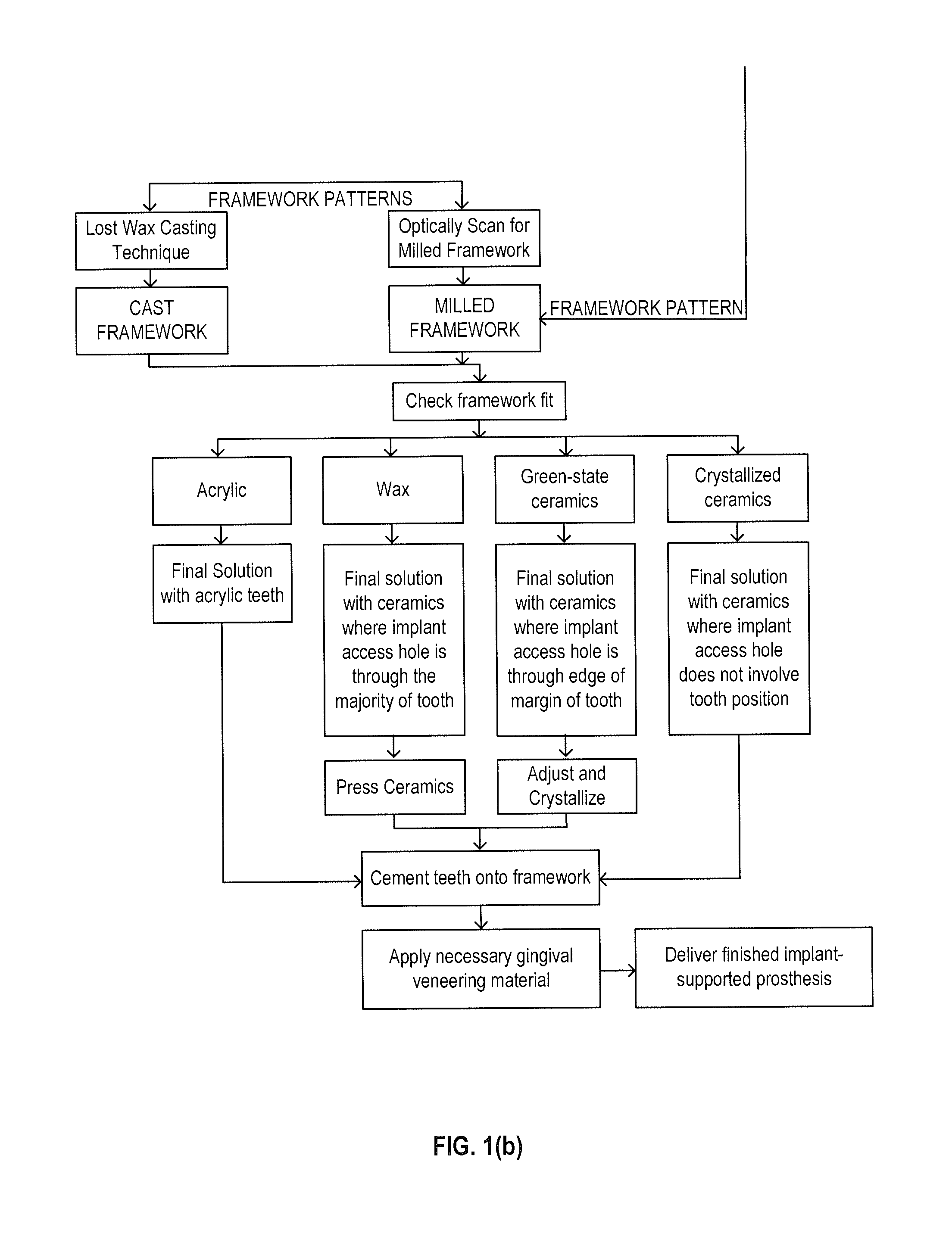
FIG. 1a is a diagram showing the process of utilizing the invention.
FIG. 1b is a diagram showing the process of utilizing the invention.
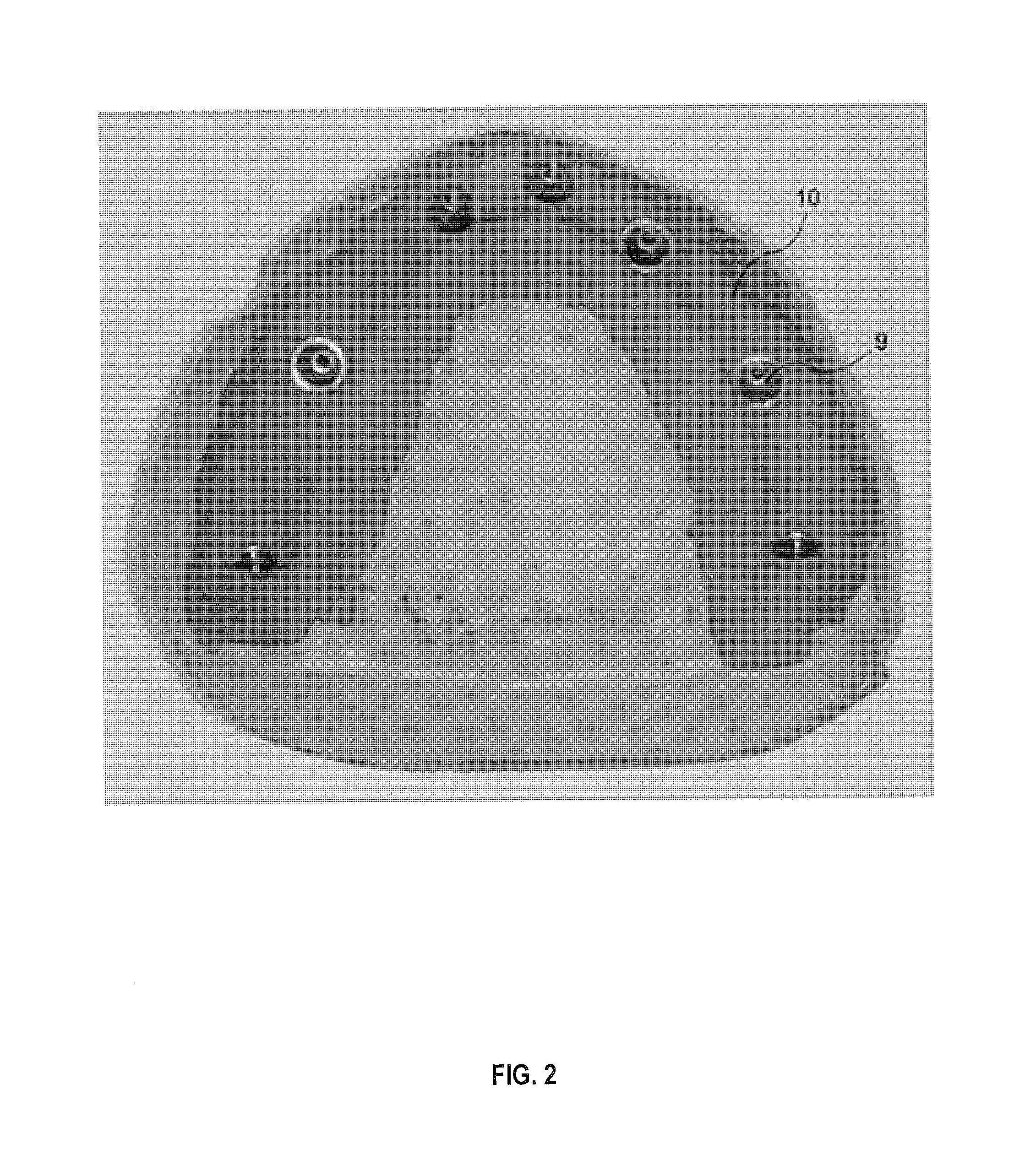
FIG. 2 is a top rear isometric view of a patient model.
FIG. 3 is a left side elevation view of a prototype setup built on the model.
FIG. 4 is a top front isometric view of a typical dental prosthetic framework.
FIG. 5 is a front isometric view showing a full set of keys and keyway teeth.
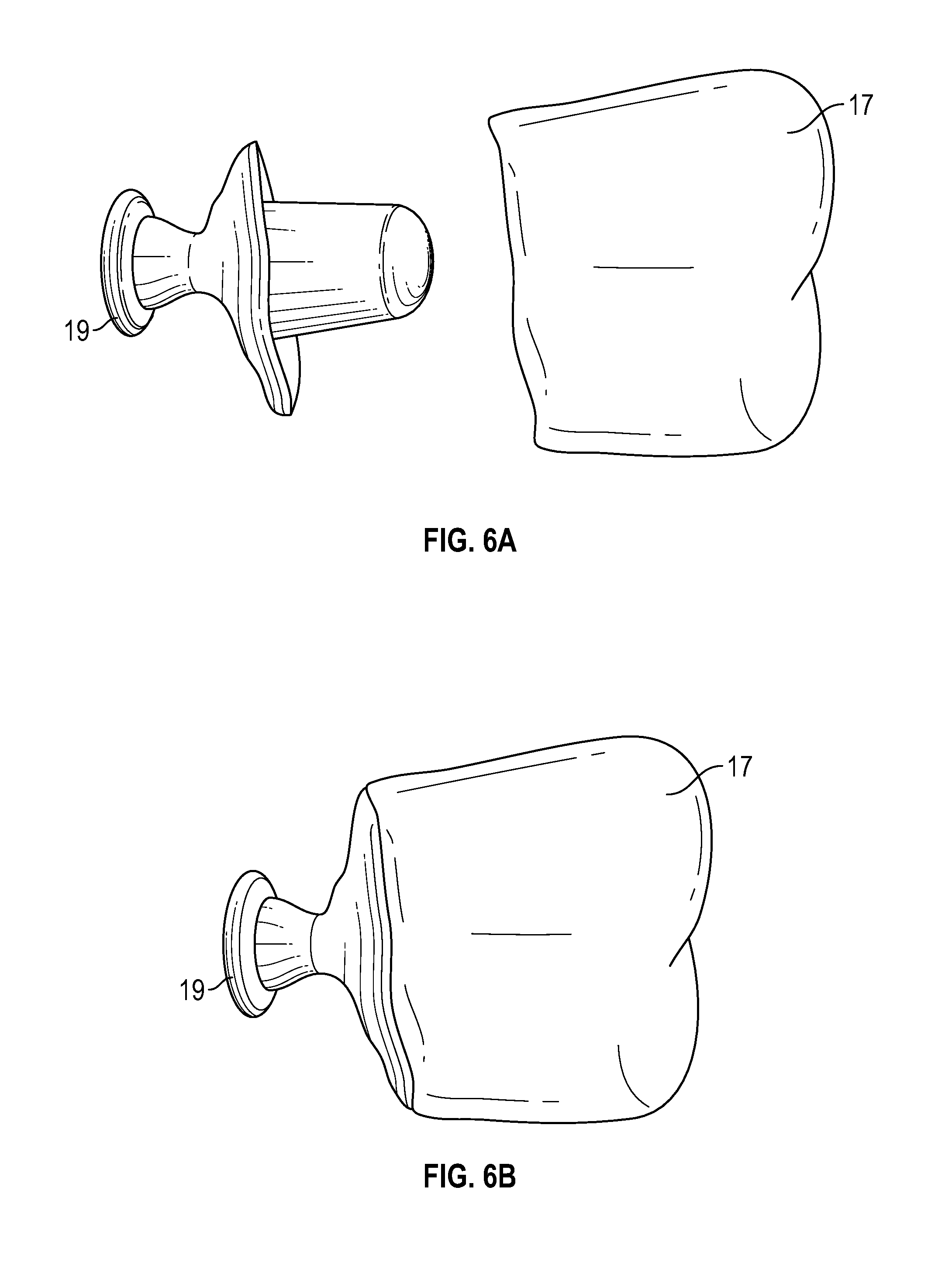
FIGS. 6a and 6b are elevation views showing the assembly of a keyed tooth pair.
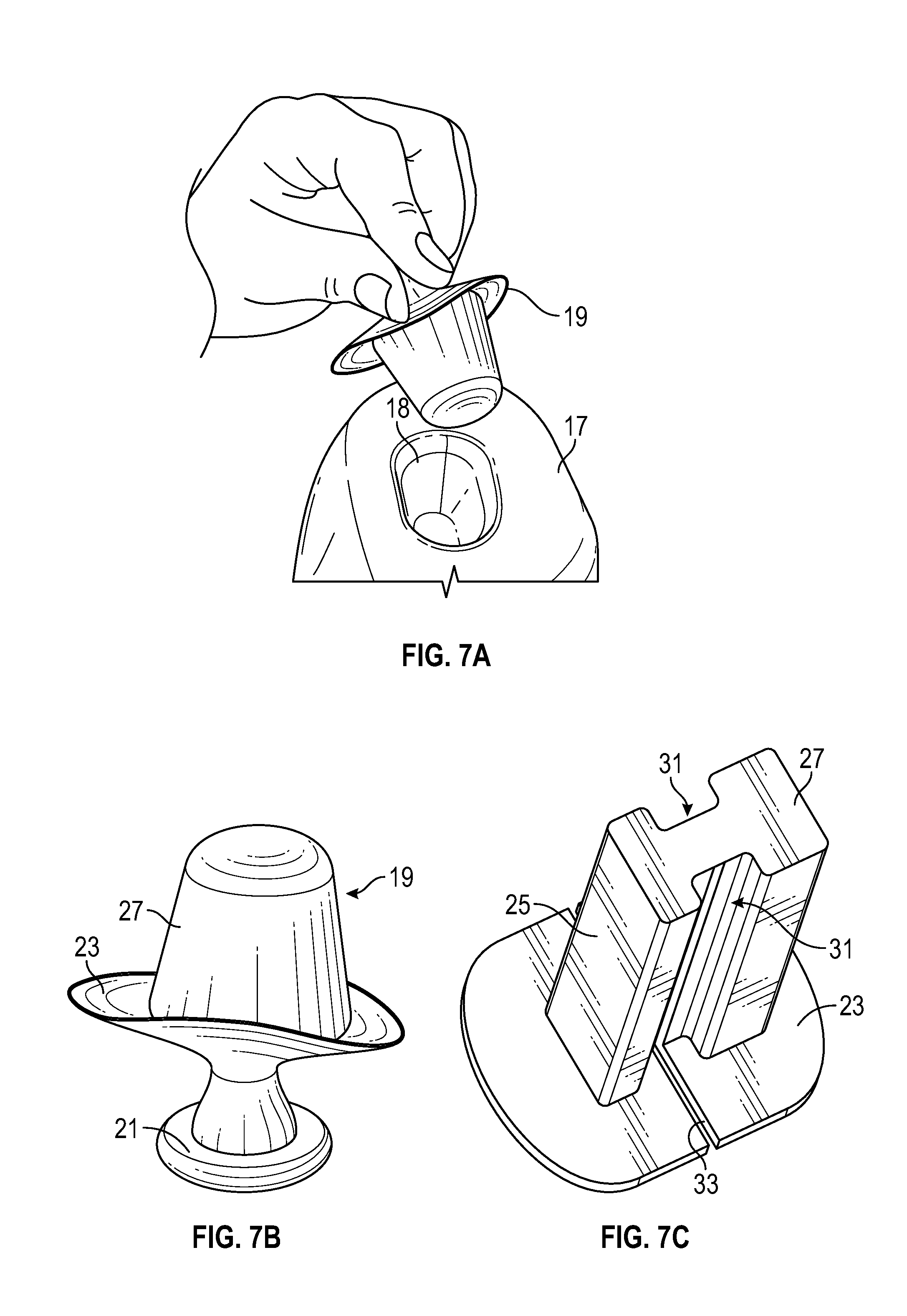
FIGS. 7a, 7b and 7c are isometric views showing detail of the keys.
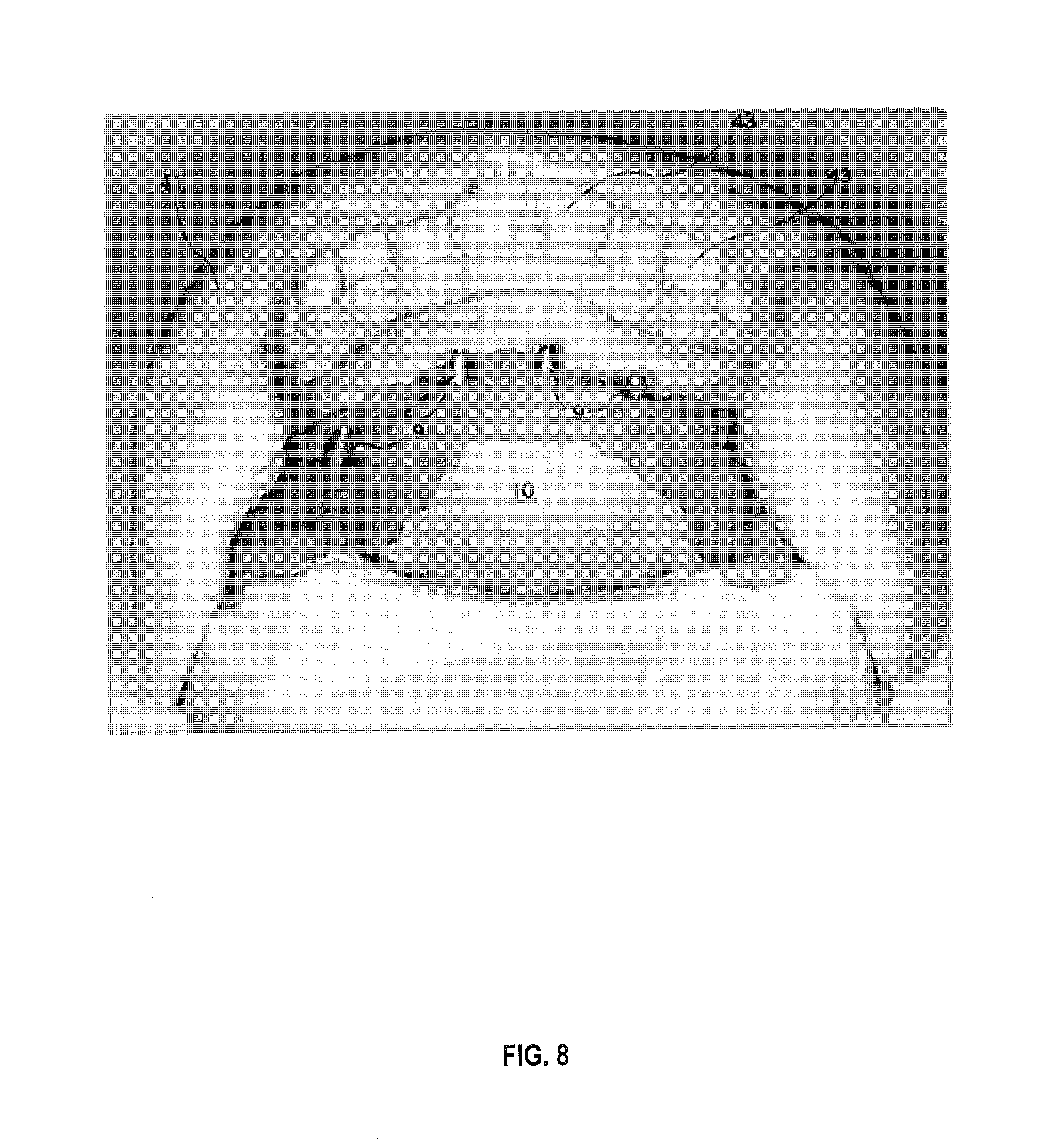
FIG. 8 is a rear view showing a matrix impression taken from the model and setup.
FIG. 9 is a rear view showing keyed teeth held in the matrix.
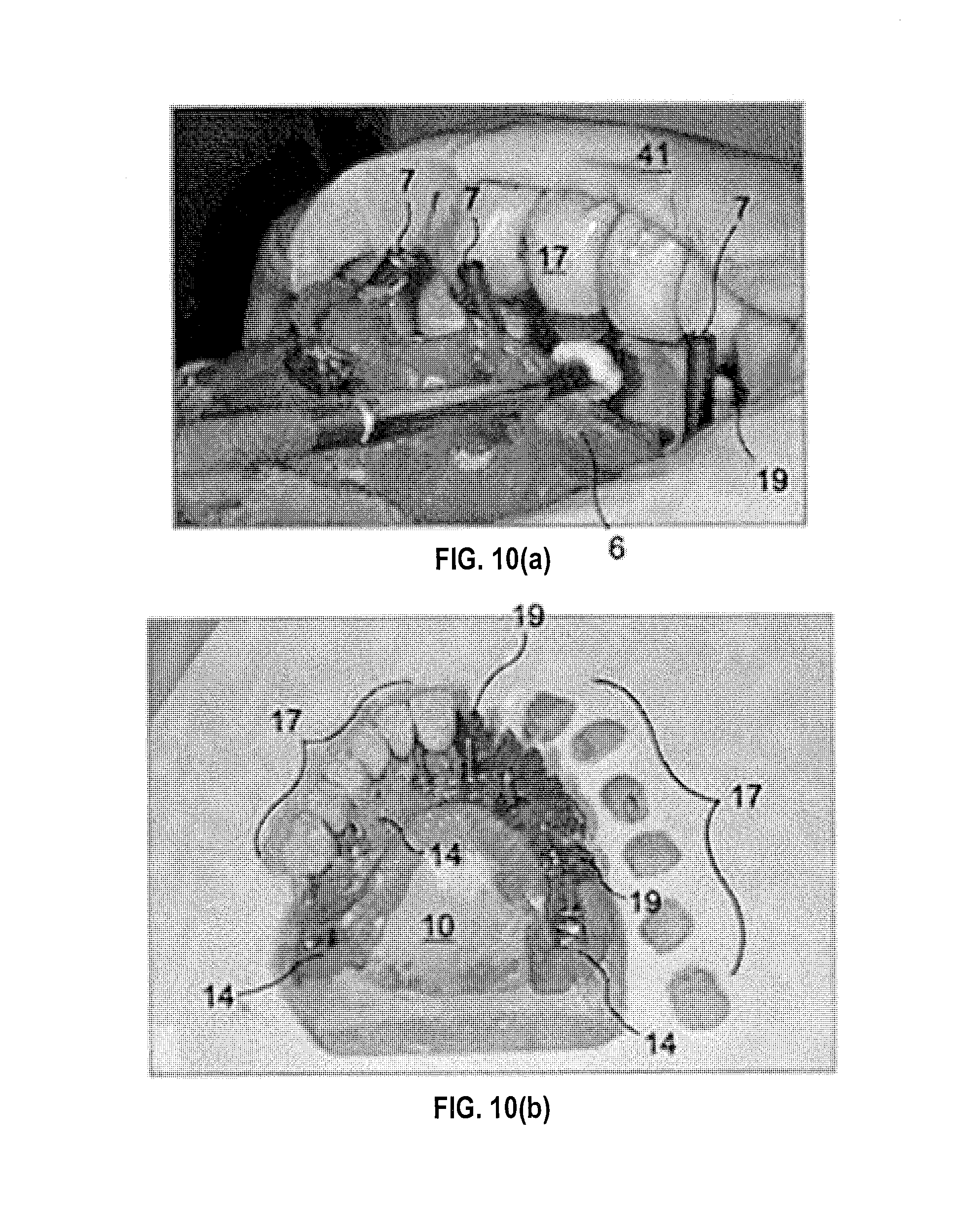
FIG. 10a is a left side top rear isometric view showing the keyed teeth molded into the horizontal beam supported by the matrix.
FIG. 10b is a top rear isometric view of the horizontal beam, keyway teeth and keys on the module with the matrix removed.
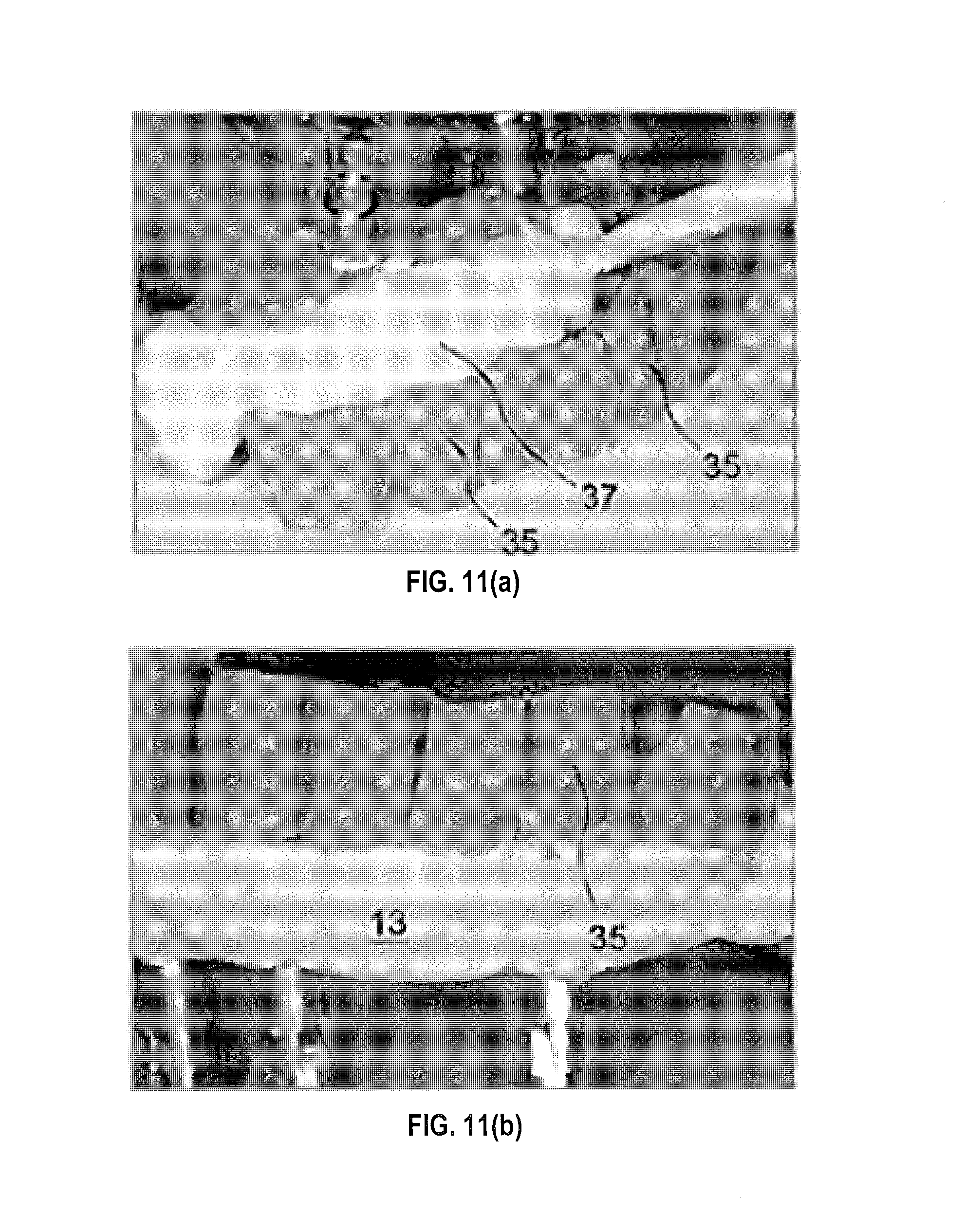
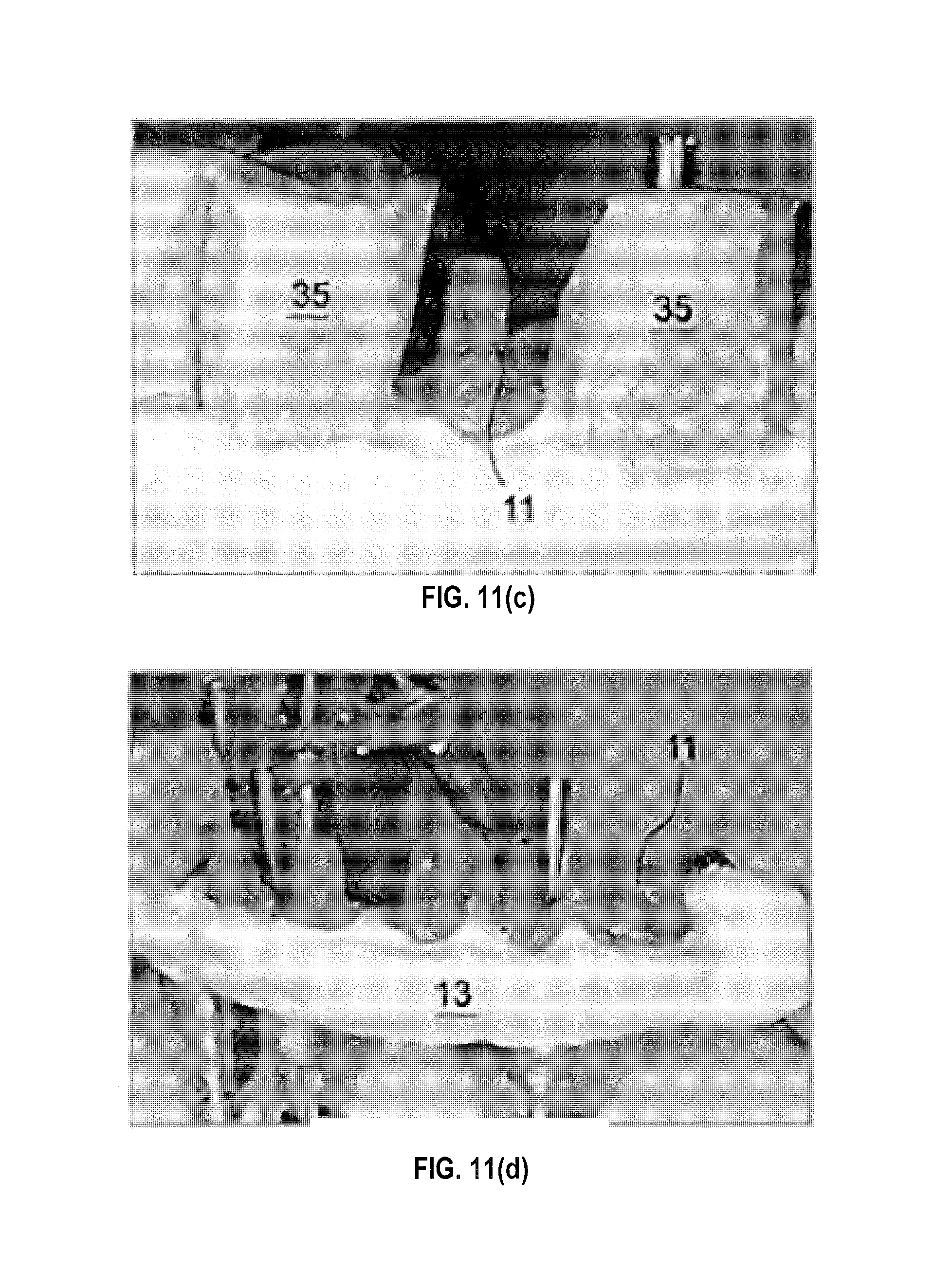
FIGS. 11a, 11b, 11c and 11d are isometric views showing the use of key protector caps in completing the horizontal beam portion of the framework pattern.
FIG. 12a depicts a completed framework pattern.
FIG. 12b shows the final casting resulting from the pattern of FIG. 12a.
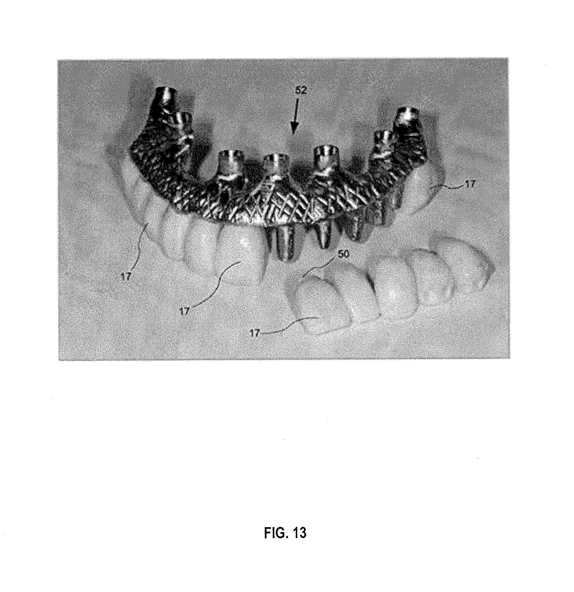
FIG. 13 is an isometric assembly view of the teeth being assembled to the completed framework.
FIG. 14 is an exploded view from the anterior side of inventive key used in the framework system,
FIG. 15 shows an embodiment of the keyway system from 14, with an isolated view of the key being mounted with a prosthetic tooth,
FIGS. 16-18 illustrates an embodiment of invention depicting side, top and perspective views of an inventive key.
DESCRIPTION OF THE PREFERRED EMBODIMENT
A step-by-step process showing the methodology and use of the novel structures comprising the invention is depicted in FIG. 1. Referring now to FIG. 2, the process begins as in current practice with the patient first receiving osseointegrated implants. From an impression of the implants including connectors, a working cast or model 10 is produced. As depicted in FIG. 3, a setup using keyway teeth 17 built on the completed working model 10 can be kept in the mouth of the patient for possible adjustments. This completes a prototype of the finished prosthesis. This is similar to current practice but with the use of novel keys and keyway teeth to form the setup, which keys and keyway teeth then are used to construct the vertical struts of the framework in the next steps of the invention. These further steps comprise designing a tooth-supporting framework which includes vertical keys positioned to hold their respective keyway teeth prescribed by the setup.
Referring now to FIG. 4, one goal of the invention is to produce a framework of this type. The basic elements of the inventive framework are the keys 11, a supporting horizontal beam 13 and implant connectors, in this example, cylinders 15 on the opposite side of the beam. The horizontal beam 13 is an intermediate connecting structure in the framework pattern or final frame, either metal or ceramic, parallel to the bite plane that unites the vertical keys supporting the teeth on one side and the implant prosthetic cylinders that connect underlying dental implants on the other side. The construction of the implant side of the horizontal beam follows current practice and therefore need not be discussed in detail. As further described herein, the main features of the invention are the keyway teeth and keys and the method by which they are employed to create the teeth-supporting abutments of a finished framework.
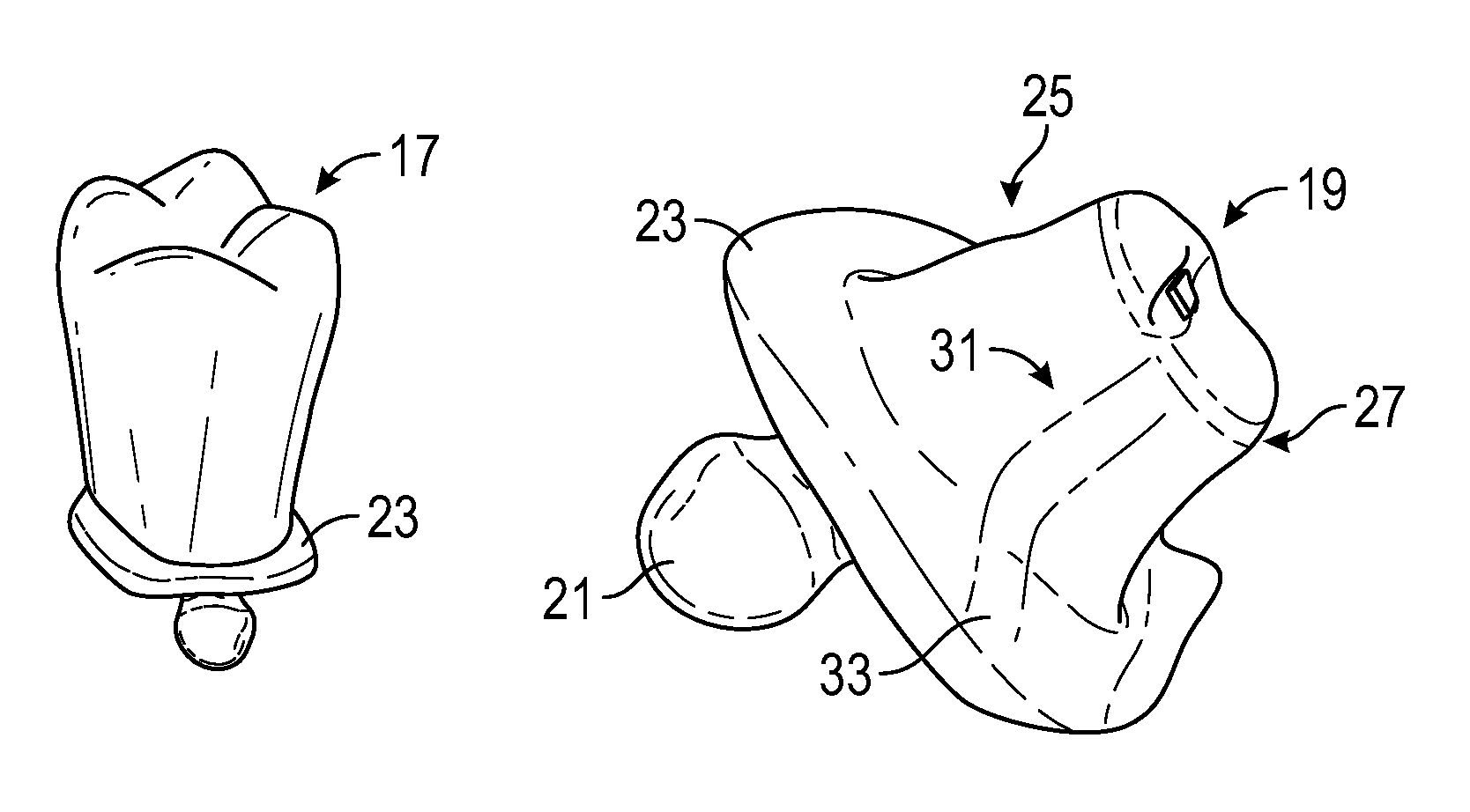
Referring now to FIG. 5, the keyway teeth 17 of the invention are full anatomic prosthetic teeth made of a variety of materials such as acrylic resin, composite, ceramic or wax. They are specifically designed for implant-supported prosthesis and are catalogued in a similar way that denture teeth are used in current fixed and removable prosthetics. Keyway teeth are so named because they have specific vertical keyways or sockets 18 inside the teeth which intimately receive specially designed pattern keys 19 as further described below and as shown in FIGS. 6a and 6b and FIGS. 7a, 7b and 7c.
The keyway teeth are preferably coated with an opaque layer for color control and are cataloged in various shapes and sizes available in numerous shades (colors) just as any traditional denture tooth line. Each different tooth geometry is provided in the above materials.
The position of the prosthetic screw access channel may dictate the selection of the material used for a given keyway tooth position. By way of example, if the prosthetic screw access channel is directly through the occlusal table of the molar, it may be advantageous to use the wax version of that keyway tooth. The wax keyway tooth can be modified with a hole to provide direct access to the prosthetic retention screw. After modification, the wax version of the keyway tooth can be invested and finalized with a pressed ceramic. In another example, if the prosthetic screw access channel impinges on the cervical margin of the keyway tooth, it may be advantageous to use the green state tooth with appropriate marginal adaptation to accommodate the screwdriver access to the retention screw. Following adaptation would be the crystallization of the green state to a solid ceramic keyway tooth. The keyway teeth also have a cervical groove 50 to aid in retention as a mechanical interlock with the gingival veneering material once the tooth is luted to the framework in a final step in the process shown in FIG. 13.
As shown in FIGS. 6a and 6b and with further detail in FIGS. 7a, 7b and 7c, the pattern keys 19 are vertical struts of various configurations that each fit precisely within the socket of a designated keyway tooth 17. The pattern keys are one of the most important aspects of the present invention. They comprise the following structural features: a retention knob 21 at a base end, a cervical platform 23 adjacent the retentive knob and an elongate tapered shaft 25 extending axially from the platform terminating at an opposite end 27 forming the coronal aspect of the key. The shaft is tapered from the cervical platform to the coronal aspect for optimal cement retention of the keyway tooth. As shown in FIG. 7c, the shaft preferably includes at least one cement release channel 33 which are formed by one or more axial grooves which lie along opposing surfaces of the shaft. Two channels are depicted in this embodiment (31, 33). This embodiment depicts an "H" cross section configuration of the shaft, however it should be understood that various shapes may be employed so long as there are no sharp edges along the surface of the key. The cement release channels run from the coronal aspect of the key to the edge of the cervical platform. The purpose of the channel(s) is to relieve hydraulic back pressure and permit the expulsion of flowable cement or other luting agents when the keyway tooth is fastened to the final unifying framework. The cervical platform 23 is the supporting base of the key that supports the cervical aspect of each keyway tooth. Incorporated into the lingual aspect of the platform is a portion of the cement release channel 33. The platforms shown are concave but may be any shape so long as it provides an intimately mating surface with the base of the tooth. The retentive knob provides a structural linkage to the horizontal beam by molding into the beam material as it is being formed. The keys are anti-rotational inside the keyway teeth so that only one position of fit exists. The keys are preferably made of a moldable and adjustable material that is chemically compatible with traditional resins and composites when they are connected to adjacent keys and the implant prosthetic cylinders to build the horizontal beam. The junction of all geometric planes of the keys should be round, avoiding any sharp angles.
One of the main advantages of the present invention is that it can utilize more commonplace dental laboratory skills and equipment or alternatively can be utilized with technologically advanced optical scanning. This makes the invention available to the greatest number of users. This more commonplace practice will now be discussed.
Once the tooth setup position has been determined, that position is recorded manually with laboratory indices or virtually in computer programming to dictate the position of the individual teeth and keys as depicted in the layout shown in FIG. 3. An impression is then taken of the setup to create a facial matrix 41 positioned on the model 10 as shown in FIG. 8.
The matrix has pockets 43 that can hold each of their respective teeth in its proper position while leaving the bottom portions of the teeth exposed as shown in FIG. 9. During this step in the process, the keys 19 remain in the sockets of their respective teeth 17. The retentive knob attachment portion of the keys extends from the base of each tooth and with the platform portion of the key in intimate contact with the base of the tooth. The matrix-supported keyed teeth are then held in juxtaposition with the implant connectors of the patient modeling.
Referring now to FIG. 10a, the retentive knobs of the keys are then joined to the implant prosthetic cylinders and to one another during the formation of the intermediate horizontal beam and supported in the setup location by the matrix 41 on the model. After the resin is set, the matrix is removed as shown in FIG. 10b. Half of the teeth in this illustration are removed to reveal the pattern keys.
Referring now to FIG. 11, the process continues with more modifiable resin material added to complete the horizontal beam portion of the framework using protective caps 35 as shown in FIGS. 11a, 11b, 11c and 11d. The protective caps 35 are installed on the keys 11 prior to the addition of the additional material 37 used to reinforce and contour the horizontal beam. The purpose of the protective caps is to prevent contamination of the keys by excess resin which could distort the pattern and prevent complete seating of the tooth on the final framework.
The horizontal beam assembly 13 is then removed from the model and the teeth removed from the keys. The remaining structure is refined providing the pattern depicted in FIG. 12a for constructing the final framework shown in FIG. 12b which can be constructed from the pattern using a variety of methods, such as:
a) Traditional lost wax technique where the framework pattern is invested, burned out and metal is cast into the mold, or
b) Copy milling using scanning technology where the framework pattern is scanned and data files are developed and transmitted to robotic milling machines for the milling of the final framework from a variety of solid materials (metal or ceramic by example).
As an option, the above-described procedure following the finished setup can be replaced by more advanced technology which permits the virtual construction of the framework from an optical scanning of the finished setup. In concert with the use of computer software which includes the three-dimensional characteristics of virtual keys that correspond to the individual scanned teeth in the setup, the location and orientation of the keys is then combined with a framework pattern that creates a file which is then copy milled by a CNC milling machine to create the final framework.
When prosthetic retention screws have their access channel coming through any portion of the keyway tooth, that tooth (either in wax or green state) will be manually or virtually modified to permit screwdriver access to the head of the screw. Acrylic, wax and green state keyway teeth may be modified or customized to accommodate the opposing occlusion, or individual cosmetic patient requirements.
With the final framework 52 completed, the selected teeth are cemented to the metal or ceramic framework as shown in FIG. 13 and the gingival veneering material is then applied to complete the prosthesis construction. A cervical groove 50 in the keyway tooth will be covered with the gingival veneering material, providing additional stability and retention of the tooth to the final framework.
Therefore, the foregoing is considered as illustrative only of the principles of the invention. Further, since numerous modifications and changes will readily occur to those skilled in the art, it is not desired to limit the invention to the exact construction and operation shown and described, and accordingly, all suitable modifications and equivalents may be resorted to, falling within the scope of the invention. For example, this invention can be applied to totally or partially edentulous patients being restored with osseointegrated dental implants.
* * * * *
D00000
D00001
D00002
D00003
D00004
D00005
D00006
D00007
D00008
D00009
D00010
D00011
D00012
D00013
D00014

D00015
D00016

D00017

XML
uspto.report is an independent third-party trademark research tool that is not affiliated, endorsed, or sponsored by the United States Patent and Trademark Office (USPTO) or any other governmental organization. The information provided by uspto.report is based on publicly available data at the time of writing and is intended for informational purposes only.
While we strive to provide accurate and up-to-date information, we do not guarantee the accuracy, completeness, reliability, or suitability of the information displayed on this site. The use of this site is at your own risk. Any reliance you place on such information is therefore strictly at your own risk.
All official trademark data, including owner information, should be verified by visiting the official USPTO website at www.uspto.gov. This site is not intended to replace professional legal advice and should not be used as a substitute for consulting with a legal professional who is knowledgeable about trademark law.