Apparatus and method for catheter navigation using endovascular energy mapping
Grunwald
U.S. patent number 10,271,762 [Application Number 15/365,872] was granted by the patent office on 2019-04-30 for apparatus and method for catheter navigation using endovascular energy mapping. This patent grant is currently assigned to Bard Access Systems, Inc.. The grantee listed for this patent is Bard Access Systems, Inc.. Invention is credited to Sorin Grunwald.


View All Diagrams
| United States Patent | 10,271,762 |
| Grunwald | April 30, 2019 |
Apparatus and method for catheter navigation using endovascular energy mapping
Abstract
Devices and methods obtain and use endovascular electrograms (or electrocardiograms/ECGs) in a number of clinical applications and settings. In one embodiment, a method for locating an indwelling medical device within a vasculature of a patient includes identifying an endovascular ECG waveform complex from an endovascular ECG signal associated with the indwelling medical device, then calculating an absolute value of the energy of the endovascular ECG waveform complex over a predetermined segment thereof. A position of the medical device within the vasculature is then determined by observation of the absolute value of the energy of the predetermined segment of the endovascular ECG waveform complex.
| Inventors: | Grunwald; Sorin (Paris, FR) | ||||||||||
|---|---|---|---|---|---|---|---|---|---|---|---|
| Applicant: |
|
||||||||||
| Assignee: | Bard Access Systems, Inc. (Salt
Lake City, UT) |
||||||||||
| Family ID: | 45771202 | ||||||||||
| Appl. No.: | 15/365,872 | ||||||||||
| Filed: | November 30, 2016 |
Prior Publication Data
| Document Identifier | Publication Date | |
|---|---|---|
| US 20170079552 A1 | Mar 23, 2017 | |
Related U.S. Patent Documents
| Application Number | Filing Date | Patent Number | Issue Date | ||
|---|---|---|---|---|---|
| 13240171 | Sep 22, 2011 | 9532724 | |||
| 13019939 | Sep 8, 2015 | 9125578 | |||
| 12854083 | Sep 20, 2016 | 9445734 | |||
| 12815331 | May 17, 2016 | 9339206 | |||
| 61213474 | Jun 12, 2009 | ||||
| 61272025 | Aug 10, 2009 | ||||
| 61282397 | Feb 2, 2010 | ||||
| 61344732 | Sep 23, 2010 | ||||
| Current U.S. Class: | 1/1 |
| Current CPC Class: | A61B 5/0006 (20130101); A61B 5/044 (20130101); A61B 5/04017 (20130101); A61M 25/003 (20130101); A61B 5/042 (20130101); A61M 25/0102 (20130101); A61M 25/0147 (20130101); A61M 25/0194 (20130101); A61B 5/0456 (20130101); A61B 5/063 (20130101); A61B 5/0408 (20130101); A61B 5/7203 (20130101); A61M 25/09 (20130101); A61B 5/06 (20130101); A61M 25/0026 (20130101); A61B 5/0452 (20130101); A61B 2034/2046 (20160201); A61M 2025/0166 (20130101); A61B 2034/2053 (20160201); A61M 2025/09116 (20130101) |
| Current International Class: | A61B 5/04 (20060101); A61B 5/044 (20060101); A61B 5/0408 (20060101); A61B 5/042 (20060101); A61B 5/0452 (20060101); A61B 5/00 (20060101); A61M 25/01 (20060101); A61B 5/0456 (20060101); A61M 25/09 (20060101); A61M 25/00 (20060101); A61B 5/06 (20060101); A61B 34/20 (20160101) |
References Cited [Referenced By]
U.S. Patent Documents
| 3133244 | May 1964 | Wojtulewicz |
| 3297020 | January 1967 | Mathiesen |
| 3625200 | December 1971 | Muller |
| 3674014 | July 1972 | Tillander et al. |
| 3795855 | March 1974 | Browning |
| 3817241 | June 1974 | Grausz |
| 3847157 | November 1974 | Caillouette et al. |
| 3868565 | February 1975 | Kuipers |
| 3896373 | July 1975 | Zelby |
| 3902501 | September 1975 | Citron et al. |
| 3986373 | October 1976 | Goodlaxson |
| 3995623 | December 1976 | Blake et al. |
| 4003369 | January 1977 | Heilman et al. |
| 4063561 | December 1977 | McKenna |
| 4072146 | February 1978 | Howes |
| 4114601 | September 1978 | Abels |
| 4149535 | April 1979 | Volder et al. |
| 4173228 | November 1979 | Steenwyk et al. |
| 4175566 | November 1979 | Millar |
| 4181120 | January 1980 | Kunii et al. |
| 4224949 | September 1980 | Scott et al. |
| 4244362 | January 1981 | Anderson |
| 4289139 | September 1981 | Enjoji et al. |
| 4317078 | February 1982 | Weed et al. |
| 4327722 | May 1982 | Groshong et al. |
| 4327723 | May 1982 | Frankhouser |
| 4362166 | December 1982 | Furler et al. |
| 4365639 | December 1982 | Goldreyer |
| 4380237 | April 1983 | Newbower |
| 4407294 | October 1983 | Vilkomerson |
| 4417886 | November 1983 | Frankhouser et al. |
| 4429693 | February 1984 | Blake et al. |
| 4431005 | February 1984 | McCormick |
| 4431214 | February 1984 | Buffington |
| 4445501 | May 1984 | Bresler |
| 4459854 | July 1984 | Richardson et al. |
| 4469106 | September 1984 | Harui |
| 4483343 | November 1984 | Beyer et al. |
| 4491137 | January 1985 | Jingu |
| 4565201 | January 1986 | Lass |
| 4572198 | February 1986 | Codrington |
| 4577634 | March 1986 | Gessman |
| 4582067 | April 1986 | Silverstein et al. |
| 4587975 | May 1986 | Salo et al. |
| 4588394 | May 1986 | Schulte et al. |
| 4593687 | June 1986 | Gray |
| 4595012 | June 1986 | Webler et al. |
| 4601706 | July 1986 | Aillon |
| 4608989 | September 1986 | Drue |
| 4608992 | September 1986 | Hakim et al. |
| 4619247 | October 1986 | Inoue et al. |
| 4622644 | November 1986 | Hansen |
| 4644960 | February 1987 | Johans |
| 4652820 | March 1987 | Maresca |
| 4660571 | April 1987 | Hess et al. |
| 4665925 | May 1987 | Millar |
| 4667230 | May 1987 | Arakawa et al. |
| 4674518 | June 1987 | Salo |
| 4676249 | June 1987 | Arenas et al. |
| 4681106 | July 1987 | Kensey et al. |
| 4681117 | July 1987 | Brodman et al. |
| 4688578 | August 1987 | Takano et al. |
| 4692148 | September 1987 | Kantrowitz et al. |
| 4697595 | October 1987 | Breyer et al. |
| 4700997 | October 1987 | Strand |
| 4706681 | November 1987 | Breyer et al. |
| 4710708 | December 1987 | Rorden et al. |
| 4733669 | March 1988 | Segal |
| 4737794 | April 1988 | Jones |
| 4741356 | May 1988 | Letzo et al. |
| 4742356 | May 1988 | Kuipers |
| 4753247 | June 1988 | Kirsner et al. |
| 4770185 | September 1988 | Silverstein et al. |
| 4771788 | September 1988 | Millar |
| 4781685 | November 1988 | Lehmann et al. |
| 4784646 | November 1988 | Feingold |
| 4787070 | November 1988 | Suzuki et al. |
| 4787396 | November 1988 | Pidorenko |
| 4790809 | December 1988 | Kuntz |
| 4793361 | December 1988 | DuFault |
| 4794930 | January 1989 | Machida et al. |
| 4796632 | January 1989 | Boyd et al. |
| 4798588 | January 1989 | Aillon |
| 4798598 | January 1989 | Bonello et al. |
| 4809681 | March 1989 | Kantrowitz et al. |
| 4809713 | March 1989 | Grayzel |
| 4813729 | March 1989 | Speckhart |
| 4821731 | April 1989 | Martinelli et al. |
| 4836214 | June 1989 | Sramek |
| 4840182 | June 1989 | Carlson |
| 4840622 | June 1989 | Hardy |
| 4841977 | June 1989 | Griffith et al. |
| 4849692 | July 1989 | Blood |
| 4850358 | July 1989 | Millar |
| 4852580 | August 1989 | Wood |
| 4856317 | August 1989 | Pidorenko et al. |
| 4856529 | August 1989 | Segal |
| 4860757 | August 1989 | Lynch et al. |
| 4867169 | September 1989 | Machida et al. |
| 4869263 | September 1989 | Segal et al. |
| 4869718 | September 1989 | Brader |
| 4873987 | October 1989 | Djordjevich et al. |
| 4887606 | December 1989 | Yock et al. |
| 4887615 | December 1989 | Taylor |
| 4889128 | December 1989 | Millar |
| 4899756 | February 1990 | Sonek |
| 4901725 | February 1990 | Nappholz et al. |
| 4905698 | March 1990 | Strohl, Jr. et al. |
| 4911173 | March 1990 | Terwilliger |
| 4911174 | March 1990 | Pederson et al. |
| 4917669 | April 1990 | Bonaldo |
| 4924870 | May 1990 | Wlodarczyk et al. |
| 4943770 | July 1990 | Ashley-Rollman et al. |
| 4945305 | July 1990 | Blood |
| 4947852 | August 1990 | Nassi et al. |
| 4957110 | September 1990 | Vogel et al. |
| 4957111 | September 1990 | Millar |
| 4961433 | October 1990 | Christian |
| 4966148 | October 1990 | Millar |
| 4967753 | November 1990 | Haase et al. |
| 4977886 | December 1990 | Takehana et al. |
| 4989608 | February 1991 | Ratner |
| 4989610 | February 1991 | Patton et al. |
| 4995396 | February 1991 | Inaba et al. |
| 4998916 | March 1991 | Hammerslag et al. |
| 5004456 | April 1991 | Botterbusch et al. |
| 5005592 | April 1991 | Cartmell |
| 5016173 | May 1991 | Kenet et al. |
| 5025799 | June 1991 | Wilson |
| 5029585 | July 1991 | Lieber et al. |
| 5040548 | August 1991 | Yock |
| 5042486 | August 1991 | Pfeiler et al. |
| 5045071 | September 1991 | McCormick et al. |
| 5046497 | September 1991 | Millar |
| 5050607 | September 1991 | Bradley et al. |
| 5057095 | October 1991 | Fabian |
| 5058583 | October 1991 | Geddes et al. |
| 5058595 | October 1991 | Kern |
| 5067489 | November 1991 | Lind |
| 5076278 | December 1991 | Vilkomerson et al. |
| 5078140 | January 1992 | Kwoh |
| 5078148 | January 1992 | Nassi et al. |
| 5078149 | January 1992 | Katsumata et al. |
| 5078678 | January 1992 | Katims |
| 5078714 | January 1992 | Katims |
| 5084022 | January 1992 | Claude |
| 5092341 | March 1992 | Kelen |
| 5099845 | March 1992 | Besz et al. |
| 5099850 | March 1992 | Matsui et al. |
| 5100387 | March 1992 | Ng |
| 5105829 | April 1992 | Fabian et al. |
| 5109862 | May 1992 | Kelen et al. |
| 5114401 | May 1992 | Stuart et al. |
| 5121750 | June 1992 | Katims |
| 5125410 | June 1992 | Misono et al. |
| 5134370 | July 1992 | Jefferts et al. |
| 5144955 | September 1992 | O'Hara |
| 5146151 | September 1992 | Korn |
| 5156151 | October 1992 | Imran |
| 5158086 | October 1992 | Brown et al. |
| 5160342 | November 1992 | Reger et al. |
| 5161536 | November 1992 | Vilkomerson et al. |
| 5174295 | December 1992 | Christian et al. |
| 5174299 | December 1992 | Nelson |
| 5184601 | February 1993 | Putman |
| 5184627 | February 1993 | de Toledo |
| 5190045 | March 1993 | Frazin |
| 5202985 | April 1993 | Goyal |
| 5205830 | April 1993 | Dassa et al. |
| 5211165 | May 1993 | Dumoulin et al. |
| 5211636 | May 1993 | Mische |
| 5212988 | May 1993 | White et al. |
| 5214615 | May 1993 | Bauer et al. |
| 5217026 | June 1993 | Stoy et al. |
| 5220924 | June 1993 | Frazin |
| 5233994 | August 1993 | Shmulewitz |
| 5235987 | August 1993 | Wolfe |
| 5239464 | August 1993 | Blair et al. |
| 5240004 | August 1993 | Walinsky et al. |
| 5243995 | September 1993 | Maier |
| 5246007 | September 1993 | Frisbie et al. |
| 5246426 | September 1993 | Lewis et al. |
| 5247171 | September 1993 | Wlodarczyk et al. |
| 5251635 | October 1993 | Dumoulin et al. |
| 5255680 | October 1993 | Darrow et al. |
| 5257636 | November 1993 | White |
| 5257979 | November 1993 | Jagpal |
| 5261409 | November 1993 | Dardel |
| 5265610 | November 1993 | Darrow et al. |
| 5265614 | November 1993 | Hayakawa et al. |
| 5267569 | December 1993 | Lienhard |
| 5269306 | December 1993 | Warnking et al. |
| 5270810 | December 1993 | Nishimura |
| 5271404 | December 1993 | Corl et al. |
| 5273025 | December 1993 | Sakiyama et al. |
| 5273042 | December 1993 | Lynch et al. |
| 5274551 | December 1993 | Corby, Jr. |
| 5275053 | January 1994 | Wlodarczyk et al. |
| 5279129 | January 1994 | Ito |
| 5279607 | January 1994 | Schentag et al. |
| 5280786 | January 1994 | Wlodarczyk et al. |
| 5287331 | February 1994 | Schindel et al. |
| 5289373 | February 1994 | Zarge et al. |
| 5292342 | March 1994 | Nelson et al. |
| 5307072 | April 1994 | Jones, Jr. |
| 5311871 | May 1994 | Yock |
| 5313949 | May 1994 | Yock |
| 5318025 | June 1994 | Dumoulin et al. |
| 5325860 | July 1994 | Seward et al. |
| 5325873 | July 1994 | Hirschi et al. |
| 5330496 | July 1994 | Alferness |
| 5331966 | July 1994 | Bennett et al. |
| 5333614 | August 1994 | Feiring |
| 5337678 | August 1994 | Grout et al. |
| 5341807 | August 1994 | Nardella |
| 5343865 | September 1994 | Gardineer et al. |
| 5345940 | September 1994 | Seward et al. |
| 5348020 | September 1994 | Hutson |
| 5350352 | September 1994 | Buchholtz et al. |
| 5357961 | October 1994 | Fields et al. |
| 5365935 | November 1994 | Righter et al. |
| 5366443 | November 1994 | Eggers et al. |
| 5368048 | November 1994 | Stoy et al. |
| 5375596 | December 1994 | Twiss et al. |
| 5376083 | December 1994 | Mische |
| 5377678 | January 1995 | Dumoulin et al. |
| 5385053 | January 1995 | Wlodarczyk et al. |
| 5385146 | January 1995 | Goldreyer |
| 5391199 | February 1995 | Ben-Haim |
| 5394876 | March 1995 | Ma |
| 5394877 | March 1995 | Orr et al. |
| 5395366 | March 1995 | D'Andrea et al. |
| 5398683 | March 1995 | Edwards et al. |
| 5398691 | March 1995 | Martin et al. |
| 5411485 | May 1995 | Tennican et al. |
| 5413107 | May 1995 | Oakley et al. |
| 5417208 | May 1995 | Winkler |
| 5417701 | May 1995 | Holmes |
| 5422478 | June 1995 | Wlodarczyk et al. |
| 5423334 | June 1995 | Jordan |
| 5423877 | June 1995 | MacKey |
| 5425367 | June 1995 | Shapiro et al. |
| 5425370 | June 1995 | Vilkomerson |
| 5425382 | June 1995 | Golden et al. |
| 5427114 | June 1995 | Colliver et al. |
| 5429132 | July 1995 | Guy et al. |
| 5429617 | July 1995 | Hammersmark et al. |
| 5431641 | July 1995 | Grozinger et al. |
| 5433729 | July 1995 | Adams et al. |
| 5437276 | August 1995 | Takada et al. |
| 5437277 | August 1995 | Dumoulin et al. |
| 5438873 | August 1995 | Wlodarczyk et al. |
| 5443066 | August 1995 | Dumoulin et al. |
| 5443489 | August 1995 | Ben-Haim |
| 5445150 | August 1995 | Dumoulin et al. |
| 5445166 | August 1995 | Taylor |
| 5450846 | September 1995 | Goldreyer |
| 5453575 | September 1995 | O'Donnell et al. |
| 5453576 | September 1995 | Krivitski |
| 5456256 | October 1995 | Schneider |
| 5456718 | October 1995 | Szymaitis |
| 5464016 | November 1995 | Nicholas et al. |
| 5474065 | December 1995 | Meathrel et al. |
| 5476090 | December 1995 | Kishi |
| 5480422 | January 1996 | Ben-Haim |
| 5487729 | January 1996 | Avellanet et al. |
| 5490522 | February 1996 | Dardel |
| 5492538 | February 1996 | Johlin, Jr. |
| 5494038 | February 1996 | Wang et al. |
| 5500011 | March 1996 | Desai |
| 5500012 | March 1996 | Brucker et al. |
| 5505205 | April 1996 | Solomon et al. |
| 5509822 | April 1996 | Negus et al. |
| 5513637 | May 1996 | Twiss et al. |
| 5515160 | May 1996 | Schulz et al. |
| 5515853 | May 1996 | Smith et al. |
| 5517989 | May 1996 | Frisbie et al. |
| 5522878 | June 1996 | Montecalvo et al. |
| 5522880 | June 1996 | Barone et al. |
| 5526812 | June 1996 | Dumoulin et al. |
| 5531664 | July 1996 | Adachi et al. |
| 5536248 | July 1996 | Weaver et al. |
| 5540230 | July 1996 | Vilkomerson |
| 5540681 | July 1996 | Strul et al. |
| 5542938 | August 1996 | Avellanet et al. |
| 5546949 | August 1996 | Frazin et al. |
| 5546951 | August 1996 | Ben-Haim |
| 5555618 | September 1996 | Winkler |
| 5558091 | September 1996 | Acker et al. |
| 5568809 | October 1996 | Ben-haim |
| D375450 | November 1996 | Bidwell et al. |
| 5570671 | November 1996 | Hickey |
| 5575291 | November 1996 | Hayakawa et al. |
| 5588442 | December 1996 | Scovil et al. |
| 5592939 | January 1997 | Martinelli |
| 5598846 | February 1997 | Peszynski |
| 5599299 | February 1997 | Weaver et al. |
| 5600330 | February 1997 | Blood |
| 5603333 | February 1997 | Konings |
| 5610967 | March 1997 | Moorman et al. |
| 5617866 | April 1997 | Marian, Jr. |
| 5622169 | April 1997 | Golden et al. |
| 5622170 | April 1997 | Schulz |
| 5622184 | April 1997 | Ashby et al. |
| 5623931 | April 1997 | Wung et al. |
| 5624430 | April 1997 | Eton et al. |
| 5626554 | May 1997 | Ryaby et al. |
| 5626870 | May 1997 | Monshipouri et al. |
| 5630419 | May 1997 | Ranalletta |
| 5638819 | June 1997 | Manwaring et al. |
| 5640967 | June 1997 | Fine et al. |
| 5644612 | July 1997 | Moorman et al. |
| 5645065 | July 1997 | Shapiro et al. |
| 5651047 | July 1997 | Moorman et al. |
| 5654864 | August 1997 | Ritter et al. |
| D383968 | September 1997 | Bidwell et al. |
| 5662115 | September 1997 | Torp et al. |
| 5665103 | September 1997 | Lafontaine et al. |
| 5665477 | September 1997 | Meathrel et al. |
| 5666473 | September 1997 | Wallace |
| 5666958 | September 1997 | Rothenberg et al. |
| 5669383 | September 1997 | Johnson |
| 5669388 | September 1997 | Vilkomerson |
| 5676159 | October 1997 | Navis |
| 5676673 | October 1997 | Ferre et al. |
| 5682890 | November 1997 | Kormos et al. |
| 5691898 | November 1997 | Rosenberg et al. |
| 5694945 | December 1997 | Ben-Haim |
| 5695479 | December 1997 | Jagpal |
| 5697377 | December 1997 | Wittkampf |
| 5699801 | December 1997 | Atalar et al. |
| 5700889 | December 1997 | Blair |
| 5701898 | December 1997 | Adam et al. |
| 5702433 | December 1997 | Taylor et al. |
| 5711299 | January 1998 | Manwaring et al. |
| 5713362 | February 1998 | Vilkomerson |
| 5713363 | February 1998 | Seward et al. |
| 5713858 | February 1998 | Heruth et al. |
| 5713946 | February 1998 | Ben-Haim |
| 5715817 | February 1998 | Stevens-Wright et al. |
| 5716389 | February 1998 | Walinsky et al. |
| 5718241 | February 1998 | Ben-Haim et al. |
| D391838 | March 1998 | Bidwell et al. |
| 5722412 | March 1998 | Pflugrath et al. |
| 5727550 | March 1998 | Montecalvo |
| 5727552 | March 1998 | Ryan |
| 5727553 | March 1998 | Saad |
| 5729055 | March 1998 | Manning |
| 5729129 | March 1998 | Acker |
| 5729584 | March 1998 | Moorman et al. |
| 5730129 | March 1998 | Darrow et al. |
| 5731996 | March 1998 | Gilbert |
| 5733323 | March 1998 | Buck et al. |
| 5738096 | April 1998 | Ben-Haim |
| 5740808 | April 1998 | Panescu et al. |
| 5742394 | April 1998 | Hansen |
| 5744953 | April 1998 | Hansen |
| 5748767 | May 1998 | Raab |
| 5749835 | May 1998 | Glantz |
| 5749938 | May 1998 | Coombs |
| 5751785 | May 1998 | Moorman et al. |
| 5752513 | May 1998 | Acker et al. |
| 5758650 | June 1998 | Miller et al. |
| 5762064 | June 1998 | Polvani |
| 5767669 | June 1998 | Hansen et al. |
| 5767960 | June 1998 | Orman et al. |
| 5769786 | June 1998 | Wiegel |
| 5769843 | June 1998 | Abela et al. |
| 5769881 | June 1998 | Schroeppel et al. |
| 5771896 | June 1998 | Sliwa, Jr. et al. |
| 5775322 | July 1998 | Silverstein et al. |
| 5775332 | July 1998 | Goldman |
| 5776064 | July 1998 | Kalfas et al. |
| 5776080 | July 1998 | Thome et al. |
| 5779638 | July 1998 | Vesely et al. |
| 5782767 | July 1998 | Pretlow, III |
| 5782773 | July 1998 | Kuo et al. |
| 5785657 | July 1998 | Breyer et al. |
| 5792055 | August 1998 | McKinnon et al. |
| 5795297 | August 1998 | Daigle |
| 5795298 | August 1998 | Vesely et al. |
| 5795632 | August 1998 | Buchalter |
| 5797849 | August 1998 | Vesely et al. |
| 5800352 | September 1998 | Ferre et al. |
| 5800410 | September 1998 | Gawreluk |
| 5800497 | September 1998 | Bakels et al. |
| 5803089 | September 1998 | Ferre et al. |
| 5810733 | September 1998 | Van Creveld et al. |
| RE35924 | October 1998 | Winkler |
| 5817022 | October 1998 | Vesely |
| 5817024 | October 1998 | Ogle et al. |
| 5820549 | October 1998 | Marian, Jr. |
| 5820560 | October 1998 | Sinderby et al. |
| 5824031 | October 1998 | Cookston et al. |
| 5827192 | October 1998 | Gopakumaran et al. |
| 5829444 | November 1998 | Ferre et al. |
| 5830145 | November 1998 | Tenhoff |
| 5831260 | November 1998 | Hansen |
| 5833608 | November 1998 | Acker |
| 5833622 | November 1998 | Meathrel et al. |
| 5835561 | November 1998 | Moorman et al. |
| 5836882 | November 1998 | Frazin |
| 5836990 | November 1998 | Li |
| 5840024 | November 1998 | Taniguchi et al. |
| 5840025 | November 1998 | Ben-Haim |
| 5840030 | November 1998 | Ferek-Petric et al. |
| 5840031 | November 1998 | Crowley |
| 5842986 | December 1998 | Avrin et al. |
| 5842998 | December 1998 | Gopakumaran et al. |
| 5843076 | December 1998 | Webster, Jr. et al. |
| 5843153 | December 1998 | Johnston et al. |
| 5844140 | December 1998 | Seale |
| 5846198 | December 1998 | Killmann |
| 5855553 | January 1999 | Tajima et al. |
| 5859893 | January 1999 | Moorman et al. |
| 5865748 | February 1999 | Co et al. |
| 5868673 | February 1999 | Vesely |
| 5873822 | February 1999 | Ferre et al. |
| 5876328 | March 1999 | Fox et al. |
| 5879297 | March 1999 | Haynor et al. |
| 5893363 | April 1999 | Little et al. |
| 5897495 | April 1999 | Aida et al. |
| 5899860 | May 1999 | Pfeiffer et al. |
| 5902238 | May 1999 | Golden et al. |
| 5907487 | May 1999 | Rosenberg et al. |
| 5908385 | June 1999 | Chechelski et al. |
| 5910113 | June 1999 | Pruter |
| 5910120 | June 1999 | Kim et al. |
| 5913820 | June 1999 | Bladen et al. |
| 5913830 | June 1999 | Miles |
| 5919141 | July 1999 | Money et al. |
| 5919170 | July 1999 | Woessner |
| 5928145 | July 1999 | Ocali et al. |
| 5929607 | July 1999 | Rosenberg et al. |
| 5931788 | August 1999 | Keen et al. |
| 5931818 | August 1999 | Werp et al. |
| 5931863 | August 1999 | Griffin, III et al. |
| 5935160 | August 1999 | Auricchio et al. |
| 5941858 | August 1999 | Johnson |
| 5941889 | August 1999 | Cermak |
| 5941904 | August 1999 | Johnston et al. |
| 5944022 | August 1999 | Nardella et al. |
| 5944023 | August 1999 | Johnson et al. |
| 5951472 | September 1999 | Van Vaals et al. |
| 5951598 | September 1999 | Bishay et al. |
| 5953683 | September 1999 | Hansen et al. |
| 5957857 | September 1999 | Hartley |
| 5961923 | October 1999 | Nova et al. |
| 5967978 | October 1999 | Littmann et al. |
| 5967980 | October 1999 | Ferre et al. |
| 5967991 | October 1999 | Gardineer et al. |
| 5969722 | October 1999 | Palm |
| 5971933 | October 1999 | Gopakumaran et al. |
| 5978705 | November 1999 | KenKnight et al. |
| 5983126 | November 1999 | Wittkampf |
| 5984908 | November 1999 | Davis et al. |
| 5991693 | November 1999 | Zalewski |
| 5997473 | December 1999 | Taniguchi et al. |
| 5997481 | December 1999 | Adams et al. |
| 6006123 | December 1999 | Nguyen et al. |
| 6011988 | January 2000 | Lynch et al. |
| 6014473 | January 2000 | Hossack et al. |
| 6014580 | January 2000 | Blume et al. |
| 6015414 | January 2000 | Werp et al. |
| 6017496 | January 2000 | Nova et al. |
| 6019724 | February 2000 | Gronningsaeter et al. |
| 6019725 | February 2000 | Vesely et al. |
| 6022342 | February 2000 | Mukherjee |
| 6023638 | February 2000 | Swanson |
| 6026312 | February 2000 | Shemwell et al. |
| 6031765 | February 2000 | Lee et al. |
| 6032070 | February 2000 | Flock et al. |
| 6039694 | March 2000 | Larson et al. |
| 6050718 | April 2000 | Schena et al. |
| 6052610 | April 2000 | Koch |
| 6052618 | April 2000 | Dahlke et al. |
| D424693 | May 2000 | Pruter |
| 6058323 | May 2000 | Lemelson |
| 6059718 | May 2000 | Taniguchi et al. |
| 6063032 | May 2000 | Grunwald |
| 6064905 | May 2000 | Webster, Jr. et al. |
| 6066094 | May 2000 | Ben-Haim |
| 6068599 | May 2000 | Saito et al. |
| 6073043 | June 2000 | Schneider |
| 6074367 | June 2000 | Hubbell |
| 6075442 | June 2000 | Welch |
| 6076007 | June 2000 | England et al. |
| 6081737 | June 2000 | Shah |
| 6082366 | July 2000 | Andra et al. |
| 6083170 | July 2000 | Ben-Haim |
| 6099524 | August 2000 | Lipson et al. |
| 6100026 | August 2000 | Nova et al. |
| 6102044 | August 2000 | Naidyhorski |
| 6102862 | August 2000 | Grunwald et al. |
| 6107699 | August 2000 | Swanson |
| 6112111 | August 2000 | Glantz |
| 6112115 | August 2000 | Feldman et al. |
| 6113504 | September 2000 | Kuesters |
| 6115624 | September 2000 | Lewis et al. |
| 6120445 | September 2000 | Grunwald |
| 6122538 | September 2000 | Sliwa, Jr. et al. |
| 6128174 | October 2000 | Ritter et al. |
| 6129668 | October 2000 | Haynor et al. |
| 6132378 | October 2000 | Marino |
| 6132379 | October 2000 | Patacsil et al. |
| 6135961 | October 2000 | Pflugrath et al. |
| 6136274 | October 2000 | Nova et al. |
| 6138681 | October 2000 | Chen et al. |
| 6139496 | October 2000 | Chen et al. |
| 6139502 | October 2000 | Fredriksen |
| 6139540 | October 2000 | Rost et al. |
| 6144300 | November 2000 | Dames et al. |
| 6148823 | November 2000 | Hastings |
| 6152933 | November 2000 | Werp et al. |
| 6157853 | December 2000 | Blume et al. |
| 6165144 | December 2000 | Talish et al. |
| 6165977 | December 2000 | Mochly-Rosen |
| 6166496 | December 2000 | Lys et al. |
| 6166806 | December 2000 | Tjin |
| 6167765 | January 2001 | Weitzel |
| 6172499 | January 2001 | Ashe |
| 6173199 | January 2001 | Gabriel |
| 6173715 | January 2001 | Sinanan et al. |
| 6175756 | January 2001 | Ferre et al. |
| 6176829 | January 2001 | Vilkomerson |
| 6187744 | February 2001 | Rooney |
| 6190370 | February 2001 | Tsui |
| 6191136 | February 2001 | Marban |
| 6193743 | February 2001 | Brayton et al. |
| 6197001 | March 2001 | Wilson et al. |
| 6200305 | March 2001 | Berthiaume et al. |
| 6203499 | March 2001 | Imling et al. |
| 6208884 | March 2001 | Kumar et al. |
| 6211626 | April 2001 | Lys et al. |
| 6211666 | April 2001 | Acker |
| 6212426 | April 2001 | Swanson |
| 6216027 | April 2001 | Willis et al. |
| 6216028 | April 2001 | Haynor et al. |
| 6216029 | April 2001 | Paltieli |
| 6217517 | April 2001 | Grunwald |
| 6223087 | April 2001 | Williams |
| 6226547 | May 2001 | Lockhart et al. |
| 6230042 | May 2001 | Slettenmark |
| 6230046 | May 2001 | Crane et al. |
| 6231518 | May 2001 | Grabek et al. |
| 6233476 | May 2001 | Strommer et al. |
| 6233994 | May 2001 | Roy et al. |
| 6236883 | May 2001 | Ciaccio et al. |
| 6238344 | May 2001 | Gamelsky et al. |
| 6241673 | June 2001 | Williams |
| 6246231 | June 2001 | Ashe |
| 6246898 | June 2001 | Vesely et al. |
| 6248072 | June 2001 | Murkin |
| 6248074 | June 2001 | Ohno et al. |
| 6248075 | June 2001 | McGee et al. |
| 6249234 | June 2001 | Ely et al. |
| 6253770 | July 2001 | Acker et al. |
| 6254543 | July 2001 | Grunwald et al. |
| 6258035 | July 2001 | Hoeksel et al. |
| 6259938 | July 2001 | Zarychta et al. |
| 6259941 | July 2001 | Chia et al. |
| 6261231 | July 2001 | Damphousse et al. |
| 6263230 | July 2001 | Haynor et al. |
| 6266550 | July 2001 | Selmon et al. |
| 6266551 | July 2001 | Osadchy et al. |
| 6266552 | July 2001 | Slettenmark |
| 6266563 | July 2001 | KenKnight et al. |
| 6270493 | August 2001 | Lalonde et al. |
| 6271833 | August 2001 | Rosenberg et al. |
| 6272371 | August 2001 | Shlomo |
| 6272374 | August 2001 | Flock et al. |
| 6275258 | August 2001 | Chim |
| 6275724 | August 2001 | Dickinson et al. |
| 6277077 | August 2001 | Brisken et al. |
| 6284459 | September 2001 | Nova et al. |
| 6285898 | September 2001 | Ben-Haim |
| 6287259 | September 2001 | Grunwald |
| 6287260 | September 2001 | Hascoet et al. |
| 6288704 | September 2001 | Flack et al. |
| 6292678 | September 2001 | Hall et al. |
| 6292680 | September 2001 | Somogyi et al. |
| 6292901 | September 2001 | Lys et al. |
| 6293955 | September 2001 | Houser et al. |
| 6296604 | October 2001 | Garibaldi et al. |
| 6298261 | October 2001 | Rex |
| 6304768 | October 2001 | Blume et al. |
| 6306097 | October 2001 | Park et al. |
| 6306105 | October 2001 | Rooney et al. |
| 6311082 | October 2001 | Creighton, IV et al. |
| 6315709 | November 2001 | Garibaldi et al. |
| 6315727 | November 2001 | Coleman et al. |
| 6319668 | November 2001 | Nova et al. |
| 6323769 | November 2001 | Dames et al. |
| 6323770 | November 2001 | Dames et al. |
| 6324416 | November 2001 | Seibert |
| 6325540 | December 2001 | Lounsberry et al. |
| 6325762 | December 2001 | Tjin |
| 6329139 | December 2001 | Nova et al. |
| 6329916 | December 2001 | Dames et al. |
| 6330467 | December 2001 | Creighton, IV et al. |
| 6332089 | December 2001 | Acker et al. |
| 6332874 | December 2001 | Eliasen et al. |
| 6340588 | January 2002 | Nova et al. |
| 6340868 | January 2002 | Lys et al. |
| 6341231 | January 2002 | Ferre et al. |
| 6346081 | February 2002 | Vilkomerson |
| 6348911 | February 2002 | Rosenberg et al. |
| 6350160 | February 2002 | Feuersanger et al. |
| 6352363 | March 2002 | Munger et al. |
| 6354999 | March 2002 | Dgany et al. |
| 6355026 | March 2002 | Mick |
| 6356791 | March 2002 | Westlund et al. |
| 6360123 | March 2002 | Kimchi et al. |
| 6361499 | March 2002 | Bates et al. |
| 6364823 | April 2002 | Garibaldi et al. |
| 6364839 | April 2002 | Little et al. |
| 6366804 | April 2002 | Mejia |
| 6368285 | April 2002 | Osadchy et al. |
| 6370411 | April 2002 | Osadchy et al. |
| 6373240 | April 2002 | Govari |
| 6373388 | April 2002 | Dames et al. |
| 6374134 | April 2002 | Bladen et al. |
| 6374670 | April 2002 | Spelman et al. |
| 6375606 | April 2002 | Garibaldi et al. |
| 6375639 | April 2002 | Duplessie et al. |
| 6377857 | April 2002 | Brayton et al. |
| 6379302 | April 2002 | Kessman et al. |
| 6379303 | April 2002 | Seitz et al. |
| 6379307 | April 2002 | Filly et al. |
| 6381485 | April 2002 | Hunter et al. |
| 6385472 | May 2002 | Hall et al. |
| 6385476 | May 2002 | Osadchy et al. |
| 6398736 | June 2002 | Seward |
| 6398738 | June 2002 | Millar |
| 6401723 | June 2002 | Garibaldi et al. |
| 6406422 | June 2002 | Landesberg |
| 6406442 | June 2002 | McFann et al. |
| 6412978 | July 2002 | Watanabe et al. |
| 6412980 | July 2002 | Lounsberry et al. |
| 6417839 | July 2002 | Odell |
| 6418332 | July 2002 | Mastrototaro et al. |
| 6418335 | July 2002 | Avrin et al. |
| 6423002 | July 2002 | Hossack |
| 6423050 | July 2002 | Twardowski |
| 6427079 | July 2002 | Schneider et al. |
| 6428551 | August 2002 | Hall et al. |
| 6430315 | August 2002 | Makram-Ebeid |
| 6432069 | August 2002 | Godo et al. |
| 6438411 | August 2002 | Guttman et al. |
| 6442416 | August 2002 | Schultz |
| 6445943 | September 2002 | Ferre et al. |
| 6456874 | September 2002 | Hafer et al. |
| 6459919 | October 2002 | Lys et al. |
| 6463121 | October 2002 | Milnes |
| 6466815 | October 2002 | Saito et al. |
| 6471656 | October 2002 | Shalman et al. |
| 6471658 | October 2002 | Daniels et al. |
| 6471700 | October 2002 | Burbank et al. |
| 6473167 | October 2002 | Odell |
| 6474341 | November 2002 | Hunter et al. |
| 6475152 | November 2002 | Kelly, Jr. et al. |
| 6475223 | November 2002 | Werp et al. |
| 6477402 | November 2002 | Lynch et al. |
| 6484118 | November 2002 | Govari et al. |
| 6487916 | December 2002 | Gomm et al. |
| 6491671 | December 2002 | Larson, III et al. |
| 6493573 | December 2002 | Martinelli et al. |
| 6494832 | December 2002 | Feldman et al. |
| 6496715 | December 2002 | Lee et al. |
| 6498944 | December 2002 | Ben-Haim et al. |
| 6500141 | December 2002 | Irion et al. |
| 6505062 | January 2003 | Ritter et al. |
| 6506159 | January 2003 | Hascoet et al. |
| 6507751 | January 2003 | Blume et al. |
| 6508802 | January 2003 | Rosengart et al. |
| 6511413 | January 2003 | Landesberg |
| 6512958 | January 2003 | Swoyer et al. |
| 6514202 | February 2003 | Grunwald |
| 6514226 | February 2003 | Levin et al. |
| 6514249 | February 2003 | Maguire et al. |
| 6515657 | February 2003 | Zanelli |
| 6516212 | February 2003 | Bladen et al. |
| 6516231 | February 2003 | Flammang |
| 6516807 | February 2003 | Panescu et al. |
| 6517520 | February 2003 | Chang et al. |
| 6522906 | February 2003 | Salisbury, Jr. et al. |
| 6522907 | February 2003 | Bladen et al. |
| 6522909 | February 2003 | Garibaldi et al. |
| 6524303 | February 2003 | Garibaldi |
| 6528954 | March 2003 | Lys et al. |
| 6528991 | March 2003 | Ashe |
| 6529761 | March 2003 | Creighton, IV et al. |
| 6529766 | March 2003 | Guendel |
| 6534982 | March 2003 | Jakab |
| 6535625 | March 2003 | Chang et al. |
| 6537192 | March 2003 | Elliott et al. |
| 6537196 | March 2003 | Creighton, IV et al. |
| 6538634 | March 2003 | Chui et al. |
| 6540699 | April 2003 | Smith et al. |
| 6542766 | April 2003 | Hall et al. |
| 6544251 | April 2003 | Crawford |
| 6545678 | April 2003 | Ohazama |
| 6546270 | April 2003 | Goldin et al. |
| 6546279 | April 2003 | Bova et al. |
| 6546787 | April 2003 | Schiller et al. |
| 6552841 | April 2003 | Lasser et al. |
| 6556858 | April 2003 | Zeman |
| 6562019 | May 2003 | Sell |
| 6564087 | May 2003 | Pitris et al. |
| 6569101 | May 2003 | Quistgaard et al. |
| 6569103 | May 2003 | Hoeksel et al. |
| 6569160 | May 2003 | Goldin et al. |
| 6569862 | May 2003 | Marban |
| 6571004 | May 2003 | Florent et al. |
| 6574518 | June 2003 | Lounsberry et al. |
| 6575908 | June 2003 | Barnes et al. |
| 6577080 | June 2003 | Lys et al. |
| 6577896 | June 2003 | Werner et al. |
| 6584343 | June 2003 | Ransbury et al. |
| 6589181 | July 2003 | Grunwald et al. |
| 6593754 | July 2003 | Steber et al. |
| 6593884 | July 2003 | Gilboa et al. |
| 6597943 | July 2003 | Taha et al. |
| 6599249 | July 2003 | Nordgren et al. |
| 6607488 | August 2003 | Jackson et al. |
| 6610058 | August 2003 | Flores |
| 6611141 | August 2003 | Schulz et al. |
| 6615071 | September 2003 | Casscells, III et al. |
| 6615155 | September 2003 | Gilboa |
| 6616610 | September 2003 | Steininger et al. |
| 6618612 | September 2003 | Acker et al. |
| 6626832 | September 2003 | Paltieli et al. |
| 6626834 | September 2003 | Dunne et al. |
| 6626902 | September 2003 | Kucharczyk et al. |
| 6630879 | October 2003 | Creighton, IV et al. |
| 6635027 | October 2003 | Cragg et al. |
| 6645148 | November 2003 | Nguyen-Dinh et al. |
| 6648875 | November 2003 | Simpson et al. |
| 6649914 | November 2003 | Moorman et al. |
| 6652505 | November 2003 | Tsugita |
| 6652506 | November 2003 | Bowe et al. |
| 6660024 | December 2003 | Flaherty et al. |
| 6662034 | December 2003 | Segner et al. |
| 6663661 | December 2003 | Boneau |
| 6666828 | December 2003 | Greco et al. |
| 6672308 | January 2004 | Gaspari |
| 6677752 | January 2004 | Creighton, IV et al. |
| 6679857 | January 2004 | Bastia et al. |
| 6684176 | January 2004 | Willins et al. |
| 6685644 | February 2004 | Seo |
| 6687531 | February 2004 | Ferre et al. |
| 6689119 | February 2004 | Di Caprio et al. |
| 6690963 | February 2004 | Ben-Haim et al. |
| 6690964 | February 2004 | Bieger et al. |
| 6690968 | February 2004 | Mejia |
| 6694167 | February 2004 | Ferre et al. |
| 6695786 | February 2004 | Wang et al. |
| 6701179 | March 2004 | Martinelli et al. |
| 6701918 | March 2004 | Fariss et al. |
| 6702804 | March 2004 | Ritter et al. |
| 6704590 | March 2004 | Haldeman |
| 6709390 | March 2004 | Marie Pop |
| 6711429 | March 2004 | Gilboa et al. |
| 6711431 | March 2004 | Sarin et al. |
| 6719699 | April 2004 | Smith |
| 6719724 | April 2004 | Walker et al. |
| 6719756 | April 2004 | Muntermann |
| 6720745 | April 2004 | Lys et al. |
| 6733458 | May 2004 | Steins et al. |
| 6733511 | May 2004 | Hall et al. |
| 6736782 | May 2004 | Pfeiffer et al. |
| 6738656 | May 2004 | Ferre et al. |
| 6740103 | May 2004 | Hall et al. |
| 6743177 | June 2004 | Ito et al. |
| 6754596 | June 2004 | Ashe |
| 6755789 | June 2004 | Stringer et al. |
| 6755816 | June 2004 | Ritter et al. |
| 6755822 | June 2004 | Reu et al. |
| 6757557 | June 2004 | Bladen et al. |
| 6763261 | July 2004 | Casscells, III et al. |
| 6764449 | July 2004 | Lee et al. |
| 6768496 | July 2004 | Bieger et al. |
| 6772001 | August 2004 | Maschke et al. |
| 6774624 | August 2004 | Anderson et al. |
| 6783536 | August 2004 | Vilsmeier et al. |
| 6784660 | August 2004 | Ashe |
| 6785571 | August 2004 | Glossop et al. |
| 6786219 | September 2004 | Garibaldi et al. |
| 6786870 | September 2004 | Miyaki et al. |
| 6788967 | September 2004 | Ben-Haim et al. |
| 6794667 | September 2004 | Noshi |
| 6799066 | September 2004 | Steines et al. |
| 6815651 | November 2004 | Odell |
| 6816266 | November 2004 | Varshneya et al. |
| 6817364 | November 2004 | Garibaldi |
| 6834201 | December 2004 | Gillies et al. |
| 6844713 | January 2005 | Steber et al. |
| 6845142 | January 2005 | Ohishi |
| 6856823 | February 2005 | Ashe |
| 6860422 | March 2005 | Hull et al. |
| 6862467 | March 2005 | Moore et al. |
| 6869390 | March 2005 | Elliott et al. |
| 6875179 | April 2005 | Ferguson et al. |
| 6879160 | April 2005 | Jakab |
| 6887206 | May 2005 | Hoeksel et al. |
| 6889091 | May 2005 | Hine et al. |
| 6895268 | May 2005 | Rahn et al. |
| 6902528 | June 2005 | Garibaldi et al. |
| 6905469 | June 2005 | Hascoet et al. |
| 6908433 | June 2005 | Pruter |
| 6911026 | June 2005 | Hall et al. |
| 6923782 | August 2005 | O'Mahony et al. |
| 6926673 | August 2005 | Roberts et al. |
| 6926674 | August 2005 | Tenerz et al. |
| 6934575 | August 2005 | Ferre et al. |
| 6936010 | August 2005 | Fang et al. |
| 6939313 | September 2005 | Saadat et al. |
| 6940379 | September 2005 | Creighton |
| 6941166 | September 2005 | MacAdam et al. |
| 6945938 | September 2005 | Grunwald |
| 6947788 | September 2005 | Gilboa et al. |
| 6950689 | September 2005 | Willis et al. |
| 6953754 | October 2005 | Machida et al. |
| 6958677 | October 2005 | Carter |
| 6959214 | October 2005 | Pape et al. |
| 6962566 | November 2005 | Quistgaard et al. |
| 6968846 | November 2005 | Viswanathan |
| 6975197 | December 2005 | Creighton, IV |
| 6976962 | December 2005 | Bullis |
| 6976987 | December 2005 | Flores |
| 6980843 | December 2005 | Eng et al. |
| 6980852 | December 2005 | Jersey-Willuhn et al. |
| 6980921 | December 2005 | Anderson et al. |
| 6986739 | January 2006 | Warren et al. |
| 6986744 | January 2006 | Krivitski |
| 6999821 | February 2006 | Jenney et al. |
| 7001355 | February 2006 | Nunomura et al. |
| 7008418 | March 2006 | Hall et al. |
| 7010338 | March 2006 | Ritter et al. |
| 7015393 | March 2006 | Weiner et al. |
| 7017584 | March 2006 | Garibaldi et al. |
| 7019610 | March 2006 | Creighton, IV et al. |
| 7020512 | March 2006 | Ritter et al. |
| D518574 | April 2006 | Chaggares |
| 7022075 | April 2006 | Grunwald et al. |
| 7022082 | April 2006 | Sonek |
| 7026927 | April 2006 | Wright et al. |
| 7027634 | April 2006 | Odell |
| 7028387 | April 2006 | Huynh et al. |
| 7029446 | April 2006 | Wendelken et al. |
| 7033603 | April 2006 | Nelson et al. |
| D520139 | May 2006 | Chaggares |
| D520140 | May 2006 | Chaggares |
| 7038398 | May 2006 | Lys et al. |
| 7038657 | May 2006 | Rosenberg et al. |
| 7043293 | May 2006 | Baura |
| 7048733 | May 2006 | Hartley et al. |
| 7054228 | May 2006 | Hickling |
| 7065403 | June 2006 | Mouchawar et al. |
| 7066914 | June 2006 | Andersen |
| 7066924 | June 2006 | Garibaldi et al. |
| 7069072 | June 2006 | Jansen et al. |
| D525363 | July 2006 | Chaggares |
| 7070565 | July 2006 | Vaezy et al. |
| 7072704 | July 2006 | Bucholz |
| 7082325 | July 2006 | Hashimshony et al. |
| 7090639 | August 2006 | Govari |
| 7096059 | August 2006 | Geddes et al. |
| 7096148 | August 2006 | Anderson et al. |
| 7096870 | August 2006 | Lamprich et al. |
| 7098907 | August 2006 | Houston et al. |
| 7103205 | September 2006 | Wang et al. |
| 7104980 | September 2006 | Laherty et al. |
| 7106043 | September 2006 | Da Silva et al. |
| 7106431 | September 2006 | Odell |
| 7106479 | September 2006 | Roy et al. |
| 7107105 | September 2006 | Bjorklund et al. |
| 7112197 | September 2006 | Hartley et al. |
| 7128734 | October 2006 | Wilson et al. |
| 7132804 | November 2006 | Lys et al. |
| 7137976 | November 2006 | Ritter et al. |
| 7141019 | November 2006 | Pearlman |
| 7141812 | November 2006 | Appleby et al. |
| 7142905 | November 2006 | Slayton et al. |
| 7148970 | December 2006 | de Boer |
| 7153291 | December 2006 | Bierman |
| 7161453 | January 2007 | Creighton, IV |
| 7162291 | January 2007 | Nachaliel |
| 7167738 | January 2007 | Schweikard et al. |
| 7169107 | January 2007 | Jersey-Willuhn et al. |
| 7169109 | January 2007 | Jansen et al. |
| 7174201 | February 2007 | Govari et al. |
| 7175646 | February 2007 | Brenneman et al. |
| 7180252 | February 2007 | Lys et al. |
| 7184820 | February 2007 | Jersey-Willuhn et al. |
| 7189198 | March 2007 | Harburn et al. |
| 7189205 | March 2007 | McMorrow et al. |
| 7189208 | March 2007 | Beatty et al. |
| 7190819 | March 2007 | Viswanathan |
| 7194295 | March 2007 | Vilsmeier |
| 7204798 | April 2007 | Zdeblick et al. |
| 7206064 | April 2007 | Rogers et al. |
| 7207941 | April 2007 | Sharf |
| 7211082 | May 2007 | Hall et al. |
| 7214191 | May 2007 | Stringer et al. |
| 7215326 | May 2007 | Rosenberg |
| 7221104 | May 2007 | Lys et al. |
| 7223256 | May 2007 | Bierman |
| 7229400 | June 2007 | Elliott et al. |
| 7231243 | June 2007 | Tearney et al. |
| 7236157 | June 2007 | Schena et al. |
| 7236816 | June 2007 | Kumar et al. |
| 7236820 | June 2007 | Mabary et al. |
| 7237313 | July 2007 | Skujins et al. |
| 7241267 | July 2007 | Furia |
| 7244234 | July 2007 | Ridley et al. |
| 7248032 | July 2007 | Hular et al. |
| 7248914 | July 2007 | Hastings et al. |
| 7252633 | August 2007 | Obata et al. |
| 7261691 | August 2007 | Asomani |
| 7264584 | September 2007 | Ritter et al. |
| 7270662 | September 2007 | Visram et al. |
| 7276044 | October 2007 | Ferry et al. |
| 7286034 | October 2007 | Creighton |
| 7291146 | November 2007 | Steinke et al. |
| 7297140 | November 2007 | Corlu et al. |
| 7299085 | November 2007 | Bergelson et al. |
| 7300430 | November 2007 | Wilson et al. |
| 7302288 | November 2007 | Schellenberg |
| 7308296 | December 2007 | Lys et al. |
| 7310150 | December 2007 | Guillermo et al. |
| 7311702 | December 2007 | Tallarida et al. |
| 7321228 | January 2008 | Govari |
| 7326241 | February 2008 | Jang |
| 7327872 | February 2008 | Vaillant et al. |
| 7331462 | February 2008 | Steppe |
| 7342058 | March 2008 | Peppmoller et al. |
| 7349732 | March 2008 | Kil et al. |
| 7355716 | April 2008 | de Boer et al. |
| 7360427 | April 2008 | Drinkwater et al. |
| 7366376 | April 2008 | Shishkov et al. |
| 7366562 | April 2008 | Dukesherer et al. |
| 7366563 | April 2008 | Kleen et al. |
| 7373271 | May 2008 | Schneider |
| 7381204 | June 2008 | Wilson et al. |
| 7382949 | June 2008 | Bouma et al. |
| 7384407 | June 2008 | Rodriguez et al. |
| 7418169 | August 2008 | Tearney et al. |
| 7447408 | November 2008 | Bouma et al. |
| 7452331 | November 2008 | Pruter |
| 7452358 | November 2008 | Stern et al. |
| 7454244 | November 2008 | Kassab et al. |
| D585556 | January 2009 | Kosaku |
| 7479141 | January 2009 | Kleen et al. |
| 7519424 | April 2009 | Dennis et al. |
| 7529584 | May 2009 | Laske et al. |
| 7534223 | May 2009 | Boutilette et al. |
| 7538859 | May 2009 | Tearney et al. |
| 7543239 | June 2009 | Viswanathan et al. |
| 7546158 | June 2009 | Allison et al. |
| 7547282 | June 2009 | Lo et al. |
| 7551293 | June 2009 | Yelin et al. |
| D603050 | October 2009 | Chen |
| 7599730 | October 2009 | Hunter et al. |
| 7606615 | October 2009 | Makower et al. |
| 7613478 | November 2009 | Jabri et al. |
| 7616992 | November 2009 | Dennis et al. |
| 7627376 | December 2009 | Dennis et al. |
| 7635336 | December 2009 | Pruter |
| 7637163 | December 2009 | Fetzer et al. |
| 7640053 | December 2009 | Verin |
| 7651469 | January 2010 | Osborne et al. |
| 7652080 | January 2010 | Peppmoller et al. |
| 7660623 | February 2010 | Hunter et al. |
| 7665893 | February 2010 | Buchalter |
| 7666191 | February 2010 | Orban, III et al. |
| 7668583 | February 2010 | Fegert et al. |
| 7697972 | April 2010 | Verard et al. |
| 7699782 | April 2010 | Angelsen et al. |
| 7699829 | April 2010 | Harris et al. |
| 7715925 | May 2010 | Hafer et al. |
| 7727192 | June 2010 | Tokumoto et al. |
| 7729743 | June 2010 | Sabczynski et al. |
| 7751865 | July 2010 | Jascob et al. |
| 7766839 | August 2010 | Rogers et al. |
| 7771437 | August 2010 | Hogg et al. |
| 7774051 | August 2010 | Voth |
| 7774055 | August 2010 | Min |
| 7794407 | September 2010 | Rothenberg |
| 7798970 | September 2010 | Lo et al. |
| 7819810 | October 2010 | Stringer et al. |
| 7822464 | October 2010 | Maschke et al. |
| 7828528 | November 2010 | Estes et al. |
| 7831294 | November 2010 | Viswanathan |
| 7833168 | November 2010 | Taylor et al. |
| 7833214 | November 2010 | Wilson et al. |
| 7840252 | November 2010 | Strommer et al. |
| D629526 | December 2010 | Ladwig et al. |
| D629527 | December 2010 | Crunkilton |
| 7846157 | December 2010 | Kozel |
| 7850613 | December 2010 | Stribling |
| D630756 | January 2011 | Kitayama |
| D630757 | January 2011 | Kitayama |
| 7869854 | January 2011 | Shachar et al. |
| 7869865 | January 2011 | Govari et al. |
| 7873402 | January 2011 | Shachar |
| 7909815 | March 2011 | Whitmore, III et al. |
| 7931596 | April 2011 | Rachlin et al. |
| 7947040 | May 2011 | Davies et al. |
| 7969142 | June 2011 | Krueger et al. |
| 7976469 | July 2011 | Bonde et al. |
| 7976518 | July 2011 | Shaughnessy et al. |
| 7981038 | July 2011 | Kanade et al. |
| 7988633 | August 2011 | Hossack et al. |
| 8016814 | September 2011 | Blakstvedt et al. |
| 8046052 | October 2011 | Verard et al. |
| 8055327 | November 2011 | Strommer et al. |
| 8057394 | November 2011 | Dala-Krishna |
| 8060185 | November 2011 | Hunter et al. |
| 8078274 | December 2011 | Kassab |
| 8078279 | December 2011 | Dennis et al. |
| 8082025 | December 2011 | Amitai et al. |
| 8082032 | December 2011 | Kassab et al. |
| 8088072 | January 2012 | Munrow et al. |
| 8090430 | January 2012 | Makower et al. |
| 8099161 | January 2012 | Kassab |
| 8105338 | January 2012 | Anderson et al. |
| 8114143 | February 2012 | Kassab et al. |
| 8118743 | February 2012 | Park et al. |
| 8123691 | February 2012 | Mine et al. |
| 8133698 | March 2012 | Silver |
| 8142417 | March 2012 | Pajunk et al. |
| 8150522 | April 2012 | Echauz et al. |
| 8152724 | April 2012 | Ridley et al. |
| 8155732 | April 2012 | Scholz et al. |
| 8204582 | June 2012 | Zantos et al. |
| 8214018 | July 2012 | Markowitz et al. |
| 8221402 | July 2012 | Francischelli et al. |
| 8240211 | August 2012 | Zeitner et al. |
| 8241274 | August 2012 | Keogh et al. |
| 8244339 | August 2012 | Shen et al. |
| 8255035 | August 2012 | Cao et al. |
| 8260395 | September 2012 | Markowitz et al. |
| 8262577 | September 2012 | Munrow et al. |
| 8298149 | October 2012 | Hastings et al. |
| 8303502 | November 2012 | Washburn et al. |
| 8303505 | November 2012 | Webler et al. |
| 8326419 | December 2012 | Rosenberg et al. |
| 8326651 | December 2012 | McLaren et al. |
| 8340751 | December 2012 | Markowitz et al. |
| 8346343 | January 2013 | Kimura et al. |
| 8369922 | February 2013 | Paul et al. |
| 8388541 | March 2013 | Messerly et al. |
| 8388546 | March 2013 | Rothenberg |
| 8391956 | March 2013 | Zellers et al. |
| 8400164 | March 2013 | Osadchy et al. |
| 8401616 | March 2013 | Verard et al. |
| 8409103 | April 2013 | Grunwald et al. |
| 8412313 | April 2013 | Amitai et al. |
| 8425425 | April 2013 | Hagy et al. |
| 8437833 | May 2013 | Silverstein |
| 8439873 | May 2013 | Donovan |
| 8442621 | May 2013 | Gorek et al. |
| 8447384 | May 2013 | Xu et al. |
| D684265 | June 2013 | Cadera |
| 8456182 | June 2013 | Bar-Tal et al. |
| 8478382 | July 2013 | Burnside et al. |
| 8478388 | July 2013 | Nguyen et al. |
| 8485980 | July 2013 | Sinderby et al. |
| 8494608 | July 2013 | Markowitz et al. |
| 8496592 | July 2013 | Ridley et al. |
| 8504139 | August 2013 | Jacobsen et al. |
| 8512256 | August 2013 | Rothenberg |
| 8521122 | August 2013 | Scott et al. |
| 8527036 | September 2013 | Jalde et al. |
| 8538509 | September 2013 | Harlev et al. |
| 8597193 | December 2013 | Grunwald et al. |
| 8620412 | December 2013 | Griffiths et al. |
| 8644907 | February 2014 | Hartmann et al. |
| 8663116 | March 2014 | Hamilton, Jr. |
| 8690776 | April 2014 | Razzaque et al. |
| 8700137 | April 2014 | Albert |
| 8715195 | May 2014 | Ziv |
| 8721655 | May 2014 | Viswanathan et al. |
| 8734440 | May 2014 | Wu |
| 8761862 | June 2014 | Ridley et al. |
| 8774907 | July 2014 | Rothenberg |
| 8781555 | July 2014 | Bumside et al. |
| 8784336 | July 2014 | Bown et al. |
| 8801693 | August 2014 | He et al. |
| 8849382 | September 2014 | Cox et al. |
| 8858455 | October 2014 | Rothenberg |
| 8934961 | January 2015 | Lakin et al. |
| 8942784 | January 2015 | Neidert et al. |
| 8965490 | February 2015 | Lee et al. |
| 8971994 | March 2015 | Burnside et al. |
| 9014794 | April 2015 | Brodnick et al. |
| 9033889 | May 2015 | Hamilton, Jr. |
| 9125578 | September 2015 | Grunwald |
| 9179860 | November 2015 | Markowitz et al. |
| 9198600 | December 2015 | Grunwald et al. |
| 9339206 | May 2016 | Grunwald |
| 9415188 | August 2016 | He et al. |
| 9456766 | October 2016 | Cox et al. |
| 9492097 | November 2016 | Wilkes et al. |
| 9521961 | December 2016 | Silverstein et al. |
| 9526440 | December 2016 | Burnside et al. |
| 9532724 | January 2017 | Grunwald |
| 9554716 | January 2017 | Burnside et al. |
| 9636031 | May 2017 | Cox |
| 9642986 | May 2017 | Beasley |
| 9649048 | May 2017 | Cox et al. |
| 9681823 | June 2017 | Messerly et al. |
| 9833169 | December 2017 | Rothenberg |
| 9839372 | December 2017 | Bukhman et al. |
| 9901714 | February 2018 | Lemon et al. |
| 9907513 | March 2018 | Silverstein |
| 9999371 | June 2018 | Messerly et al. |
| 10004875 | June 2018 | Bown et al. |
| 10046139 | August 2018 | Owers et al. |
| 10105121 | October 2018 | Burnside et al. |
| 2001/0014774 | August 2001 | Grunwald |
| 2001/0027332 | October 2001 | Grunwald et al. |
| 2002/0010392 | January 2002 | Desai |
| 2002/0016549 | February 2002 | Mejia |
| 2002/0019447 | February 2002 | Renn et al. |
| 2002/0022777 | February 2002 | Crieghton et al. |
| 2002/0032391 | March 2002 | McFann et al. |
| 2002/0049488 | April 2002 | Boneau |
| 2002/0055680 | May 2002 | Miele et al. |
| 2002/0082559 | June 2002 | Chang et al. |
| 2002/0113555 | August 2002 | Lys et al. |
| 2002/0123679 | September 2002 | Dominguez |
| 2002/0128554 | September 2002 | Seward |
| 2002/0129952 | September 2002 | Matsudate et al. |
| 2002/0133079 | September 2002 | Sandhu |
| 2002/0156363 | October 2002 | Hunter et al. |
| 2002/0156376 | October 2002 | Wang et al. |
| 2002/0165448 | November 2002 | Ben-Haim et al. |
| 2002/0165534 | November 2002 | Hayzelden et al. |
| 2002/0165537 | November 2002 | Kelley et al. |
| 2002/0173721 | November 2002 | Grunwald et al. |
| 2002/0193756 | December 2002 | Prindle |
| 2002/0198568 | December 2002 | Hafer et al. |
| 2003/0009132 | January 2003 | Schwartz et al. |
| 2003/0011359 | January 2003 | Ashe |
| 2003/0013959 | January 2003 | Grunwald et al. |
| 2003/0013966 | January 2003 | Barnes et al. |
| 2003/0013986 | January 2003 | Saadat |
| 2003/0018251 | January 2003 | Solomon |
| 2003/0036696 | February 2003 | Willis et al. |
| 2003/0040671 | February 2003 | Somogyi et al. |
| 2003/0040743 | February 2003 | Cosman et al. |
| 2003/0072805 | April 2003 | Miyazawa et al. |
| 2003/0073901 | April 2003 | Simon et al. |
| 2003/0076281 | April 2003 | Morgan et al. |
| 2003/0083698 | May 2003 | Whitehurst et al. |
| 2003/0088195 | May 2003 | Vardi et al. |
| 2003/0092993 | May 2003 | Grunwald |
| 2003/0100849 | May 2003 | Jang |
| 2003/0114742 | June 2003 | Lewkowicz et al. |
| 2003/0114777 | June 2003 | Griffin et al. |
| 2003/0120150 | June 2003 | Govari |
| 2003/0120154 | June 2003 | Sauer et al. |
| 2003/0139661 | July 2003 | Kimchy et al. |
| 2003/0149328 | August 2003 | Elliott et al. |
| 2003/0149368 | August 2003 | Hennemann et al. |
| 2003/0152290 | August 2003 | Odell |
| 2003/0160721 | August 2003 | Gilboa et al. |
| 2003/0162414 | August 2003 | Schulz et al. |
| 2003/0163037 | August 2003 | Bladen et al. |
| 2003/0163142 | August 2003 | Paltieli et al. |
| 2003/0171691 | September 2003 | Casscells et al. |
| 2003/0173953 | September 2003 | Ashe |
| 2003/0181892 | September 2003 | Pajunk et al. |
| 2003/0184544 | October 2003 | Prudent |
| 2003/0191392 | October 2003 | Haldeman |
| 2003/0191460 | October 2003 | Hobbs et al. |
| 2003/0195420 | October 2003 | Mendlein et al. |
| 2003/0199746 | October 2003 | Fuimaono et al. |
| 2003/0208142 | November 2003 | Boudewijn et al. |
| 2003/0216639 | November 2003 | Gilboa et al. |
| 2003/0220557 | November 2003 | Cleary et al. |
| 2003/0220578 | November 2003 | Ho et al. |
| 2003/0229298 | December 2003 | Iwami et al. |
| 2003/0233042 | December 2003 | Ashe |
| 2003/0236445 | December 2003 | Couvillon |
| 2004/0010189 | January 2004 | van Sloun et al. |
| 2004/0015070 | January 2004 | Liang et al. |
| 2004/0024301 | February 2004 | Hockett et al. |
| 2004/0030319 | February 2004 | Korkor et al. |
| 2004/0054278 | March 2004 | Kimchy et al. |
| 2004/0059217 | March 2004 | Kessman et al. |
| 2004/0059237 | March 2004 | Narayan et al. |
| 2004/0082916 | April 2004 | Jenkins |
| 2004/0087877 | May 2004 | Besz et al. |
| 2004/0088136 | May 2004 | Ashe |
| 2004/0092962 | May 2004 | Thornton et al. |
| 2004/0097803 | May 2004 | Panescu |
| 2004/0097804 | May 2004 | Sobe |
| 2004/0097805 | May 2004 | Verard et al. |
| 2004/0097806 | May 2004 | Hunter et al. |
| 2004/0116809 | June 2004 | Chow et al. |
| 2004/0127805 | July 2004 | MacAdam et al. |
| 2004/0131998 | July 2004 | Marom et al. |
| 2004/0133111 | July 2004 | Szczech et al. |
| 2004/0133130 | July 2004 | Ferry et al. |
| 2004/0135069 | July 2004 | Odell |
| 2004/0138557 | July 2004 | Le et al. |
| 2004/0138564 | July 2004 | Hwang et al. |
| 2004/0138569 | July 2004 | Grunwald et al. |
| 2004/0138570 | July 2004 | Nita et al. |
| 2004/0147837 | July 2004 | Macaulay et al. |
| 2004/0150963 | August 2004 | Holmberg et al. |
| 2004/0152972 | August 2004 | Hunter |
| 2004/0155609 | August 2004 | Lys et al. |
| 2004/0158140 | August 2004 | Fuimaono et al. |
| 2004/0171924 | September 2004 | Mire et al. |
| 2004/0176688 | September 2004 | Haldeman |
| 2004/0186461 | September 2004 | DiMatteo |
| 2004/0199069 | October 2004 | Connelly et al. |
| 2004/0210289 | October 2004 | Wang et al. |
| 2004/0225233 | November 2004 | Frankowski et al. |
| 2004/0230131 | November 2004 | Kassab et al. |
| 2004/0230271 | November 2004 | Wang et al. |
| 2004/0234453 | November 2004 | Smith |
| 2004/0243018 | December 2004 | Organ et al. |
| 2004/0243116 | December 2004 | Joye et al. |
| 2004/0243118 | December 2004 | Ayers et al. |
| 2004/0253365 | December 2004 | Warren et al. |
| 2004/0254470 | December 2004 | Drinkwater et al. |
| 2004/0254495 | December 2004 | Mabary et al. |
| 2004/0260174 | December 2004 | Keene |
| 2004/0267086 | December 2004 | Anstadt et al. |
| 2005/0004450 | January 2005 | Ben-Haim et al. |
| 2005/0021019 | January 2005 | Hashimshony et al. |
| 2005/0033150 | February 2005 | Takahashi et al. |
| 2005/0038355 | February 2005 | Gellman et al. |
| 2005/0043640 | February 2005 | Chang |
| 2005/0049486 | March 2005 | Urquhart et al. |
| 2005/0049510 | March 2005 | Haldeman et al. |
| 2005/0063194 | March 2005 | Lys et al. |
| 2005/0070788 | March 2005 | Wilson et al. |
| 2005/0075561 | April 2005 | Golden |
| 2005/0085715 | April 2005 | Dukesherer et al. |
| 2005/0085716 | April 2005 | Hamm et al. |
| 2005/0085718 | April 2005 | Shahidi |
| 2005/0085720 | April 2005 | Jascob et al. |
| 2005/0090746 | April 2005 | Ohtake |
| 2005/0101868 | May 2005 | Ridley et al. |
| 2005/0101869 | May 2005 | Burba et al. |
| 2005/0105081 | May 2005 | Odell |
| 2005/0105101 | May 2005 | Duling et al. |
| 2005/0112135 | May 2005 | Cormier et al. |
| 2005/0113669 | May 2005 | Helfer et al. |
| 2005/0113676 | May 2005 | Weiner et al. |
| 2005/0113700 | May 2005 | Yanagihara et al. |
| 2005/0113873 | May 2005 | Weiner et al. |
| 2005/0113874 | May 2005 | Connelly et al. |
| 2005/0113876 | May 2005 | Weiner et al. |
| 2005/0148836 | July 2005 | Kleen et al. |
| 2005/0148902 | July 2005 | Minar et al. |
| 2005/0149002 | July 2005 | Wang et al. |
| 2005/0151489 | July 2005 | Lys et al. |
| 2005/0154308 | July 2005 | Quistgaard et al. |
| 2005/0159644 | July 2005 | Takano |
| 2005/0159790 | July 2005 | Shalev |
| 2005/0165301 | July 2005 | Smith et al. |
| 2005/0165313 | July 2005 | Byron et al. |
| 2005/0175665 | August 2005 | Hunter et al. |
| 2005/0175703 | August 2005 | Hunter et al. |
| 2005/0178395 | August 2005 | Hunter et al. |
| 2005/0178396 | August 2005 | Hunter et al. |
| 2005/0182295 | August 2005 | Soper et al. |
| 2005/0182454 | August 2005 | Gharib et al. |
| 2005/0197674 | September 2005 | McCabe et al. |
| 2005/0203368 | September 2005 | Verin |
| 2005/0203396 | September 2005 | Angelsen et al. |
| 2005/0205081 | September 2005 | Barker et al. |
| 2005/0215901 | September 2005 | Anderson et al. |
| 2005/0215945 | September 2005 | Harris et al. |
| 2005/0222532 | October 2005 | Bertolero et al. |
| 2005/0240102 | October 2005 | Rachlin et al. |
| 2005/0245811 | November 2005 | Scheffler |
| 2005/0256398 | November 2005 | Hastings et al. |
| 2005/0256451 | November 2005 | Adams et al. |
| 2005/0256521 | November 2005 | Kozel |
| 2005/0256541 | November 2005 | Stypulkowski |
| 2005/0283210 | December 2005 | Blischak et al. |
| 2005/0283216 | December 2005 | Pyles |
| 2005/0288586 | December 2005 | Ferek-Petric |
| 2006/0009759 | January 2006 | Chrisitian et al. |
| 2006/0015003 | January 2006 | Moaddes et al. |
| 2006/0025677 | February 2006 | Verard et al. |
| 2006/0025697 | February 2006 | Kurzweil et al. |
| 2006/0058633 | March 2006 | Hoshino et al. |
| 2006/0068074 | March 2006 | Stefandl |
| 2006/0084867 | April 2006 | Tremblay et al. |
| 2006/0106306 | May 2006 | Essner et al. |
| 2006/0116571 | June 2006 | Maschke et al. |
| 2006/0116576 | June 2006 | McGee et al. |
| 2006/0116578 | June 2006 | Grunwald et al. |
| 2006/0122514 | June 2006 | Byrd et al. |
| 2006/0142656 | June 2006 | Malackowski et al. |
| 2006/0149134 | July 2006 | Soper et al. |
| 2006/0173251 | August 2006 | Govari et al. |
| 2006/0173329 | August 2006 | Irioka et al. |
| 2006/0173407 | August 2006 | Shaughnessy et al. |
| 2006/0176242 | August 2006 | Jaramaz et al. |
| 2006/0184074 | August 2006 | Vaezy et al. |
| 2006/0206037 | September 2006 | Braxton |
| 2006/0211944 | September 2006 | Mauge et al. |
| 2006/0217655 | September 2006 | Vitullo et al. |
| 2006/0217755 | September 2006 | Eversull et al. |
| 2006/0224188 | October 2006 | Libbus et al. |
| 2006/0241432 | October 2006 | Herline et al. |
| 2006/0247746 | November 2006 | Danek et al. |
| 2006/0253029 | November 2006 | Altmann et al. |
| 2006/0258895 | November 2006 | Maschke |
| 2006/0276867 | December 2006 | Viswanathan |
| 2006/0287595 | December 2006 | Maschke |
| 2007/0010753 | January 2007 | MacAdam |
| 2007/0016007 | January 2007 | Govari et al. |
| 2007/0016013 | January 2007 | Camus |
| 2007/0016068 | January 2007 | Grunwald et al. |
| 2007/0016069 | January 2007 | Grunwald et al. |
| 2007/0016070 | January 2007 | Grunwald et al. |
| 2007/0016072 | January 2007 | Grunwald et al. |
| 2007/0032746 | February 2007 | Sell |
| 2007/0038113 | February 2007 | Oonuki et al. |
| 2007/0049817 | March 2007 | Preiss et al. |
| 2007/0049822 | March 2007 | Bunce et al. |
| 2007/0049846 | March 2007 | Bown et al. |
| 2007/0055141 | March 2007 | Kruger et al. |
| 2007/0055142 | March 2007 | Webler |
| 2007/0055294 | March 2007 | Giap |
| 2007/0060992 | March 2007 | Pappone |
| 2007/0062544 | March 2007 | Rauk Bergstrom et al. |
| 2007/0066888 | March 2007 | Maschke |
| 2007/0073155 | March 2007 | Park et al. |
| 2007/0078343 | April 2007 | Kawashima et al. |
| 2007/0087038 | April 2007 | Richardson et al. |
| 2007/0093710 | April 2007 | Maschke |
| 2007/0100236 | May 2007 | McMorrow et al. |
| 2007/0100285 | May 2007 | Griffin et al. |
| 2007/0112282 | May 2007 | Skujins et al. |
| 2007/0123805 | May 2007 | Shireman et al. |
| 2007/0129770 | June 2007 | Younis |
| 2007/0135803 | June 2007 | Belson |
| 2007/0135886 | June 2007 | Maschke |
| 2007/0156205 | July 2007 | Larson et al. |
| 2007/0161853 | July 2007 | Yagi et al. |
| 2007/0161914 | July 2007 | Zdeblick et al. |
| 2007/0161915 | July 2007 | Desai |
| 2007/0167738 | July 2007 | Timinger et al. |
| 2007/0167762 | July 2007 | Kim et al. |
| 2007/0167769 | July 2007 | Ikuma et al. |
| 2007/0167801 | July 2007 | Webler et al. |
| 2007/0167997 | July 2007 | Forsberg et al. |
| 2007/0197891 | August 2007 | Shachar et al. |
| 2007/0197905 | August 2007 | Timinger et al. |
| 2007/0197926 | August 2007 | Danehorn et al. |
| 2007/0208255 | September 2007 | Ridley et al. |
| 2007/0219453 | September 2007 | Kremliovsky et al. |
| 2007/0225589 | September 2007 | Viswanathan |
| 2007/0225610 | September 2007 | Mickley et al. |
| 2007/0232882 | October 2007 | Glossop et al. |
| 2007/0232896 | October 2007 | Gilboa et al. |
| 2007/0238984 | October 2007 | Maschke et al. |
| 2007/0239018 | October 2007 | Fetzer et al. |
| 2007/0244413 | October 2007 | Biggins |
| 2007/0247454 | October 2007 | Rahn et al. |
| 2007/0249911 | October 2007 | Simon |
| 2007/0255270 | November 2007 | Carney |
| 2007/0265526 | November 2007 | Govari et al. |
| 2007/0280974 | December 2007 | Son et al. |
| 2007/0282196 | December 2007 | Birk et al. |
| 2007/0282197 | December 2007 | Bill et al. |
| 2007/0299352 | December 2007 | Harlev et al. |
| 2007/0299353 | December 2007 | Harlev et al. |
| 2008/0004652 | January 2008 | Abboud et al. |
| 2008/0008745 | January 2008 | Stinchcomb et al. |
| 2008/0009720 | January 2008 | Schefelker et al. |
| 2008/0015442 | January 2008 | Watson et al. |
| 2008/0027320 | January 2008 | Bolorforosh et al. |
| 2008/0033283 | February 2008 | Dellaca et al. |
| 2008/0033316 | February 2008 | Kassab et al. |
| 2008/0033350 | February 2008 | Wilson et al. |
| 2008/0045908 | February 2008 | Gould et al. |
| 2008/0051626 | February 2008 | Sato et al. |
| 2008/0077158 | March 2008 | Haider et al. |
| 2008/0081958 | April 2008 | Denison et al. |
| 2008/0082136 | April 2008 | Gaudiani |
| 2008/0097232 | April 2008 | Rothenberg |
| 2008/0108949 | May 2008 | Beasley et al. |
| 2008/0114095 | May 2008 | Peppmoller et al. |
| 2008/0119697 | May 2008 | Vadodaria et al. |
| 2008/0125772 | May 2008 | Stone et al. |
| 2008/0137927 | June 2008 | Altmann et al. |
| 2008/0139944 | June 2008 | Weymer et al. |
| 2008/0146939 | June 2008 | McMorrow et al. |
| 2008/0146940 | June 2008 | Jenkins et al. |
| 2008/0146941 | June 2008 | Dala-Krishna |
| 2008/0146942 | June 2008 | Dala-Krishna |
| 2008/0154100 | June 2008 | Thalmeier et al. |
| 2008/0166453 | July 2008 | Steele et al. |
| 2008/0171934 | July 2008 | Greenan et al. |
| 2008/0183075 | July 2008 | Govari et al. |
| 2008/0188830 | August 2008 | Rosenblatt et al. |
| 2008/0190438 | August 2008 | Harlev et al. |
| 2008/0195169 | August 2008 | Pinter et al. |
| 2008/0200754 | August 2008 | Buchalter |
| 2008/0200801 | August 2008 | Wildes et al. |
| 2008/0200913 | August 2008 | Viswanathan |
| 2008/0228082 | September 2008 | Scheirer et al. |
| 2008/0236598 | October 2008 | Gobel |
| 2008/0255404 | October 2008 | Nogawa et al. |
| 2008/0255475 | October 2008 | Kondrosky et al. |
| 2008/0269581 | October 2008 | Wood et al. |
| 2008/0269611 | October 2008 | Pedrizzetti et al. |
| 2008/0275465 | November 2008 | Paul et al. |
| 2008/0275765 | November 2008 | Kuchar |
| 2008/0288038 | November 2008 | Paul et al. |
| 2008/0294041 | November 2008 | Kassab |
| 2008/0319350 | December 2008 | Wallace et al. |
| 2009/0005674 | January 2009 | Saadat et al. |
| 2009/0005675 | January 2009 | Grunwald et al. |
| 2009/0018497 | January 2009 | Birchard et al. |
| 2009/0024018 | January 2009 | Boyden et al. |
| 2009/0030380 | January 2009 | Binmoeller |
| 2009/0043205 | February 2009 | Pelissier et al. |
| 2009/0062646 | March 2009 | Creighton, IV et al. |
| 2009/0062684 | March 2009 | Gregersen et al. |
| 2009/0062772 | March 2009 | Wakeford et al. |
| 2009/0080738 | March 2009 | Zur et al. |
| 2009/0082661 | March 2009 | Saladin et al. |
| 2009/0084382 | April 2009 | Jalde et al. |
| 2009/0099468 | April 2009 | Thiagalingam et al. |
| 2009/0101577 | April 2009 | Fulkerson et al. |
| 2009/0115406 | May 2009 | Anderson et al. |
| 2009/0118612 | May 2009 | Grunwald et al. |
| 2009/0118637 | May 2009 | Kassab et al. |
| 2009/0118706 | May 2009 | Schweikert et al. |
| 2009/0124901 | May 2009 | Fink et al. |
| 2009/0143736 | June 2009 | Mittermeyer et al. |
| 2009/0156926 | June 2009 | Messerly et al. |
| 2009/0163810 | June 2009 | Kanade et al. |
| 2009/0171217 | July 2009 | Kim et al. |
| 2009/0177083 | July 2009 | Matsumura |
| 2009/0177090 | July 2009 | Grunwald et al. |
| 2009/0203989 | August 2009 | Burnside et al. |
| 2009/0204113 | August 2009 | MacAdam et al. |
| 2009/0209872 | August 2009 | Pop |
| 2009/0209950 | August 2009 | Starksen |
| 2009/0221908 | September 2009 | Glossop |
| 2009/0227952 | September 2009 | Blakstvedt et al. |
| 2009/0234328 | September 2009 | Cox et al. |
| 2009/0253976 | October 2009 | Harlev et al. |
| 2009/0258171 | October 2009 | Uang |
| 2009/0259124 | October 2009 | Rothenberg |
| 2009/0262982 | October 2009 | Markowitz et al. |
| 2009/0270729 | October 2009 | Corbucci et al. |
| 2009/0270746 | October 2009 | Min |
| 2009/0275828 | November 2009 | Shachar et al. |
| 2009/0281419 | November 2009 | Troesken et al. |
| 2009/0297441 | December 2009 | Canham et al. |
| 2009/0312629 | December 2009 | Razzaque et al. |
| 2010/0004543 | January 2010 | Ahlund et al. |
| 2010/0004547 | January 2010 | Scholz et al. |
| 2010/0010355 | January 2010 | Kassab |
| 2010/0010444 | January 2010 | Bettuchi |
| 2010/0010612 | January 2010 | Gelbart et al. |
| 2010/0016726 | January 2010 | Meier |
| 2010/0036227 | February 2010 | Cox et al. |
| 2010/0036284 | February 2010 | Laynes et al. |
| 2010/0041973 | February 2010 | Vu et al. |
| 2010/0041984 | February 2010 | Shapland et al. |
| 2010/0049062 | February 2010 | Ziv |
| 2010/0055153 | March 2010 | Majmudar |
| 2010/0055184 | March 2010 | Zeitels et al. |
| 2010/0057157 | March 2010 | Govari et al. |
| 2010/0060472 | March 2010 | Kimura et al. |
| 2010/0063401 | March 2010 | Nishina et al. |
| 2010/0076305 | March 2010 | Maier-Hein et al. |
| 2010/0076328 | March 2010 | Matsumura et al. |
| 2010/0081934 | April 2010 | Soltani et al. |
| 2010/0083719 | April 2010 | Peppmoller et al. |
| 2010/0094116 | April 2010 | Silverstein |
| 2010/0106011 | April 2010 | Byrd et al. |
| 2010/0113917 | May 2010 | Anderson |
| 2010/0114573 | May 2010 | Huang et al. |
| 2010/0117659 | May 2010 | Osadchy et al. |
| 2010/0130858 | May 2010 | Arai et al. |
| 2010/0143119 | June 2010 | Kooijman et al. |
| 2010/0152596 | June 2010 | Griffiths et al. |
| 2010/0152604 | June 2010 | Kaula et al. |
| 2010/0160772 | June 2010 | Gardeski et al. |
| 2010/0168557 | July 2010 | Deno et al. |
| 2010/0185097 | July 2010 | Hall |
| 2010/0198048 | August 2010 | Togawa |
| 2010/0198346 | August 2010 | Keogh et al. |
| 2010/0204569 | August 2010 | Burnside et al. |
| 2010/0204614 | August 2010 | Lindquist et al. |
| 2010/0210938 | August 2010 | Verard et al. |
| 2010/0210950 | August 2010 | Dunbar et al. |
| 2010/0217116 | August 2010 | Eck et al. |
| 2010/0222664 | September 2010 | Lemon et al. |
| 2010/0222786 | September 2010 | Kassab |
| 2010/0234724 | September 2010 | Jacobsen et al. |
| 2010/0234733 | September 2010 | Wahlheim |
| 2010/0249598 | September 2010 | Smith et al. |
| 2010/0258033 | October 2010 | Yang et al. |
| 2010/0268059 | October 2010 | Ryu et al. |
| 2010/0273895 | October 2010 | Stinchcomb et al. |
| 2010/0274150 | October 2010 | Harlev et al. |
| 2010/0291521 | November 2010 | Simon |
| 2010/0298702 | November 2010 | Rogers et al. |
| 2010/0298704 | November 2010 | Pelissier et al. |
| 2010/0298705 | November 2010 | Pelissier et al. |
| 2010/0298712 | November 2010 | Pelissier et al. |
| 2010/0312086 | December 2010 | Beatty et al. |
| 2010/0317981 | December 2010 | Grunwald |
| 2010/0318026 | December 2010 | Grunwald |
| 2010/0331712 | December 2010 | Rothenberg |
| 2011/0015496 | January 2011 | Sherman et al. |
| 2011/0015527 | January 2011 | Heasty et al. |
| 2011/0015533 | January 2011 | Cox et al. |
| 2011/0034823 | February 2011 | Gelbart et al. |
| 2011/0034940 | February 2011 | Payner |
| 2011/0040212 | February 2011 | Dietz et al. |
| 2011/0052694 | March 2011 | Stinchcomb et al. |
| 2011/0087105 | April 2011 | Ridley et al. |
| 2011/0087106 | April 2011 | Ridley et al. |
| 2011/0087107 | April 2011 | Lindekugel et al. |
| 2011/0106101 | May 2011 | Tortonese et al. |
| 2011/0112396 | May 2011 | Shachar et al. |
| 2011/0136242 | June 2011 | Marx et al. |
| 2011/0137156 | June 2011 | Razzaque et al. |
| 2011/0196235 | August 2011 | Dunbar et al. |
| 2011/0196248 | August 2011 | Grunwald |
| 2011/0196255 | August 2011 | Kassab |
| 2011/0237935 | September 2011 | Kalpin et al. |
| 2011/0245659 | October 2011 | Ma et al. |
| 2011/0282187 | November 2011 | Harlev et al. |
| 2011/0282188 | November 2011 | Burnside et al. |
| 2011/0282285 | November 2011 | Blanchard et al. |
| 2011/0282686 | November 2011 | Venon et al. |
| 2011/0295108 | December 2011 | Cox et al. |
| 2011/0306859 | December 2011 | Saldivar et al. |
| 2011/0306867 | December 2011 | Gopinathan et al. |
| 2011/0313293 | December 2011 | Lindekugel et al. |
| 2012/0004564 | January 2012 | Dobak, III |
| 2012/0035460 | February 2012 | Stangenes et al. |
| 2012/0046562 | February 2012 | Powers et al. |
| 2012/0059249 | March 2012 | Verard et al. |
| 2012/0059270 | March 2012 | Grunwald |
| 2012/0059271 | March 2012 | Amitai et al. |
| 2012/0071751 | March 2012 | Sra et al. |
| 2012/0071759 | March 2012 | Hagy et al. |
| 2012/0071782 | March 2012 | Patil et al. |
| 2012/0078342 | March 2012 | Vollkron et al. |
| 2012/0095319 | April 2012 | Kondrosky et al. |
| 2012/0108950 | May 2012 | He et al. |
| 2012/0143029 | June 2012 | Silverstein et al. |
| 2012/0143078 | June 2012 | Kassab et al. |
| 2012/0172727 | July 2012 | Hastings et al. |
| 2012/0220854 | August 2012 | Messerly et al. |
| 2012/0265084 | October 2012 | Stewart et al. |
| 2012/0283582 | November 2012 | Mahapatra et al. |
| 2012/0296200 | November 2012 | Shachar et al. |
| 2012/0310052 | December 2012 | Mahapatra et al. |
| 2012/0310066 | December 2012 | Shachar et al. |
| 2012/0310660 | December 2012 | Liu et al. |
| 2012/0316440 | December 2012 | Munrow et al. |
| 2013/0006100 | January 2013 | Shachar et al. |
| 2013/0006102 | January 2013 | Wilkes et al. |
| 2013/0018248 | January 2013 | Hurezan |
| 2013/0035590 | February 2013 | Ma et al. |
| 2013/0041254 | February 2013 | Hagy et al. |
| 2013/0041269 | February 2013 | Stahmann et al. |
| 2013/0060116 | March 2013 | Messerly et al. |
| 2013/0079628 | March 2013 | Groszmann et al. |
| 2013/0085416 | April 2013 | Mest |
| 2013/0090938 | April 2013 | Fishman et al. |
| 2013/0102890 | April 2013 | Dib |
| 2013/0123597 | May 2013 | Rothenberg |
| 2013/0131503 | May 2013 | Schneider et al. |
| 2013/0169272 | July 2013 | Eichler et al. |
| 2013/0217999 | August 2013 | Burnside et al. |
| 2013/0245434 | September 2013 | Messerly et al. |
| 2013/0281837 | October 2013 | Ridley et al. |
| 2013/0289417 | October 2013 | Grunwald et al. |
| 2013/0296691 | November 2013 | Ashe |
| 2013/0296693 | November 2013 | Wenzel et al. |
| 2013/0303878 | November 2013 | Nevo et al. |
| 2013/0303896 | November 2013 | Kalpin et al. |
| 2013/0303945 | November 2013 | Blumenkranz et al. |
| 2013/0317338 | November 2013 | Silverstein |
| 2013/0324841 | December 2013 | Kamen et al. |
| 2013/0338503 | December 2013 | Cohen et al. |
| 2013/0338517 | December 2013 | Rothenberg |
| 2013/0345555 | December 2013 | Kanade et al. |
| 2014/0031674 | January 2014 | Newman et al. |
| 2014/0046261 | February 2014 | Newman et al. |
| 2014/0089836 | March 2014 | Damani et al. |
| 2014/0094694 | April 2014 | Moctezuma de la Barrera |
| 2014/0094768 | April 2014 | Stangenes et al. |
| 2014/0107475 | April 2014 | Cox et al. |
| 2014/0128712 | May 2014 | Banet et al. |
| 2014/0163356 | June 2014 | Burnside et al. |
| 2014/0180074 | June 2014 | Green et al. |
| 2014/0187917 | July 2014 | Clark et al. |
| 2014/0187990 | July 2014 | Banet et al. |
| 2014/0188133 | July 2014 | Misener |
| 2014/0221862 | August 2014 | Tambe |
| 2014/0228689 | August 2014 | Ishikawa et al. |
| 2014/0243659 | August 2014 | Rothenberg |
| 2014/0249428 | September 2014 | Ingold, Jr. et al. |
| 2014/0249505 | September 2014 | Bukhman |
| 2014/0253270 | September 2014 | Nicholls et al. |
| 2014/0257080 | September 2014 | Dunbar et al. |
| 2014/0275957 | September 2014 | Lupotti |
| 2014/0275990 | September 2014 | Hagy et al. |
| 2014/0276010 | September 2014 | Anderson |
| 2014/0309624 | October 2014 | Bown et al. |
| 2014/0343398 | November 2014 | He et al. |
| 2015/0005621 | January 2015 | Liu |
| 2015/0018701 | January 2015 | Cox et al. |
| 2015/0025365 | January 2015 | Esguerra Wilczynski et al. |
| 2015/0025402 | January 2015 | Rothenberg |
| 2015/0051489 | February 2015 | Caluser et al. |
| 2015/0073285 | March 2015 | Albert et al. |
| 2015/0080716 | March 2015 | Powers et al. |
| 2015/0209008 | July 2015 | Ridley et al. |
| 2015/0216445 | August 2015 | Carmeli et al. |
| 2015/0216446 | August 2015 | Bukhman et al. |
| 2015/0223775 | August 2015 | Hamilton, Jr. |
| 2015/0245809 | September 2015 | Hagy et al. |
| 2015/0245872 | September 2015 | Hagy et al. |
| 2015/0246247 | September 2015 | Binnekamp et al. |
| 2015/0282734 | October 2015 | Schweikert et al. |
| 2015/0289781 | October 2015 | Grunwald et al. |
| 2015/0297114 | October 2015 | Cox et al. |
| 2015/0317810 | November 2015 | Grunwald et al. |
| 2015/0335310 | November 2015 | Bernstein et al. |
| 2015/0335383 | November 2015 | Cohen |
| 2016/0067449 | March 2016 | Misener et al. |
| 2016/0278869 | September 2016 | Grunwald |
| 2016/0374589 | December 2016 | Misener et al. |
| 2017/0000367 | January 2017 | Grunwald |
| 2017/0020561 | January 2017 | Cox et al. |
| 2017/0079548 | March 2017 | Silverstein et al. |
| 2017/0079615 | March 2017 | Burnside et al. |
| 2017/0079681 | March 2017 | Burnside et al. |
| 2017/0086782 | March 2017 | Hagy et al. |
| 2017/0151022 | June 2017 | Jascob et al. |
| 2017/0215762 | August 2017 | Burnside et al. |
| 2017/0231700 | August 2017 | Cox et al. |
| 2017/0281029 | October 2017 | Messerly et al. |
| 2018/0070856 | March 2018 | Grunwald |
| 2018/0103869 | April 2018 | Bukhman et al. |
| 2018/0116551 | May 2018 | Newman et al. |
| 2018/0169389 | June 2018 | Lemon et al. |
| 642647 | Nov 1990 | AU | |||
| 1860597 | Jun 1999 | AU | |||
| 20009592 | Sep 2000 | AU | |||
| 20015250 | Jun 2001 | AU | |||
| 768362 | Dec 2003 | AU | |||
| 2001229024 | Sep 2005 | AU | |||
| 2001283703 | May 2006 | AU | |||
| 2006202149 | Jun 2006 | AU | |||
| 2006904933 | Sep 2006 | AU | |||
| 2006283022 | Feb 2012 | AU | |||
| 2420676 | Feb 2002 | CA | |||
| 2619909 | Jan 2014 | CA | |||
| 2031655 | Feb 1989 | CN | |||
| 1672649 | Sep 2005 | CN | |||
| 1913833 | Feb 2007 | CN | |||
| 101854853 | Oct 2010 | CN | |||
| 102209490 | Oct 2011 | CN | |||
| 102802514 | Nov 2012 | CN | |||
| 102821679 | Dec 2012 | CN | |||
| 103037761 | Apr 2013 | CN | |||
| 103037762 | Apr 2013 | CN | |||
| 103118591 | May 2013 | CN | |||
| 103189009 | Jul 2013 | CN | |||
| 1319033 | Jun 1994 | DE | |||
| 0359697 | Mar 1990 | EP | |||
| 0362821 | Apr 1990 | EP | |||
| 0399536 | Nov 1990 | EP | |||
| 0823261 | Feb 1998 | EP | |||
| 0928976 | Jul 1999 | EP | |||
| 1025805 | Aug 2000 | EP | |||
| 1015967 | Apr 2002 | EP | |||
| 1311226 | May 2003 | EP | |||
| 1504713 | Feb 2005 | EP | |||
| 1117331 | May 2005 | EP | |||
| 1117332 | Aug 2005 | EP | |||
| 1118019 | May 2006 | EP | |||
| 1717601 | Nov 2006 | EP | |||
| 1887940 | Feb 2008 | EP | |||
| 1932477 | Jun 2008 | EP | |||
| 2337491 | Jun 2011 | EP | |||
| 2440122 | Apr 2012 | EP | |||
| 2464407 | Jun 2012 | EP | |||
| 2482719 | Aug 2012 | EP | |||
| 2531098 | Dec 2012 | EP | |||
| 2575610 | Apr 2013 | EP | |||
| 2575611 | Apr 2013 | EP | |||
| 2603145 | Jun 2013 | EP | |||
| 2605699 | Jun 2013 | EP | |||
| 2474268 | Jul 2013 | EP | |||
| 2618727 | Jul 2013 | EP | |||
| 2632360 | Sep 2013 | EP | |||
| 2219526 | Mar 2014 | EP | |||
| 2712547 | Apr 2014 | EP | |||
| 2313143 | Sep 2014 | EP | |||
| 2992825 | May 2017 | EP | |||
| 2170162 | Aug 2017 | EP | |||
| 2265175 | Aug 2017 | EP | |||
| 2545349 | Nov 1984 | FR | |||
| 01097440 | Apr 1989 | JP | |||
| 03173542 | Jul 1991 | JP | |||
| 4090741 | Aug 1992 | JP | |||
| 9-503054 | Mar 1997 | JP | |||
| 09-094298 | Apr 1997 | JP | |||
| 10043310 | Feb 1998 | JP | |||
| 10290839 | Nov 1998 | JP | |||
| 11128237 | May 1999 | JP | |||
| 2001-145630 | May 2001 | JP | |||
| 2001161683 | Jun 2001 | JP | |||
| 2001-514533 | Sep 2001 | JP | |||
| 2001-524339 | Dec 2001 | JP | |||
| 2001340334 | Dec 2001 | JP | |||
| 2002-224069 | Aug 2002 | JP | |||
| 2002-529133 | Sep 2002 | JP | |||
| 2002-541947 | Dec 2002 | JP | |||
| 2003-010138 | Jan 2003 | JP | |||
| 2003501127 | Jan 2003 | JP | |||
| 2003061752 | Mar 2003 | JP | |||
| 2003299654 | Oct 2003 | JP | |||
| 2003334191 | Nov 2003 | JP | |||
| 2002520893 | Feb 2004 | JP | |||
| 2004505748 | Feb 2004 | JP | |||
| 2004515298 | May 2004 | JP | |||
| 2006508744 | Mar 2006 | JP | |||
| 2006-338526 | Dec 2006 | JP | |||
| 2007-000226 | Jan 2007 | JP | |||
| 2007-068989 | Mar 2007 | JP | |||
| 2007-105450 | Apr 2007 | JP | |||
| 2007-313122 | Dec 2007 | JP | |||
| 2009/271123 | Nov 2009 | JP | |||
| 5010604 | Jun 2012 | JP | |||
| 2012-529929 | Nov 2012 | JP | |||
| 2013-518676 | May 2013 | JP | |||
| 2013-526959 | Jun 2013 | JP | |||
| 2013-526961 | Jun 2013 | JP | |||
| 2009101949 | Jul 2010 | RU | |||
| 1980002376 | Nov 1980 | WO | |||
| 1991012836 | Sep 1991 | WO | |||
| 1992003090 | Mar 1992 | WO | |||
| 1994003159 | Feb 1994 | WO | |||
| 1994004938 | Mar 1994 | WO | |||
| 1996005768 | Feb 1996 | WO | |||
| 1996007352 | Mar 1996 | WO | |||
| 1996041119 | Dec 1996 | WO | |||
| 1997/22395 | Jun 1997 | WO | |||
| 1997029683 | Aug 1997 | WO | |||
| 1997043989 | Nov 1997 | WO | |||
| 97/48438 | Dec 1997 | WO | |||
| 1998025159 | Jun 1998 | WO | |||
| 98/29032 | Jul 1998 | WO | |||
| 1998035611 | Aug 1998 | WO | |||
| 1999016495 | Apr 1999 | WO | |||
| 1999027837 | Jun 1999 | WO | |||
| 1999049407 | Sep 1999 | WO | |||
| 2000019906 | Apr 2000 | WO | |||
| 2000027281 | May 2000 | WO | |||
| 2000040155 | Jul 2000 | WO | |||
| 2000063658 | Oct 2000 | WO | |||
| 2000074775 | Dec 2000 | WO | |||
| 2001013792 | Mar 2001 | WO | |||
| 2001039683 | Jun 2001 | WO | |||
| 2001076479 | Oct 2001 | WO | |||
| 02/07794 | Jan 2002 | WO | |||
| 2002015973 | Feb 2002 | WO | |||
| 2002019905 | Mar 2002 | WO | |||
| 2002025277 | Mar 2002 | WO | |||
| 2002085442 | Oct 2002 | WO | |||
| 2003061752 | Jul 2003 | WO | |||
| 2003077759 | Sep 2003 | WO | |||
| 03/088833 | Oct 2003 | WO | |||
| 2003091495 | Nov 2003 | WO | |||
| 2004002303 | Jan 2004 | WO | |||
| 2004049970 | Jun 2004 | WO | |||
| 2005033524 | Apr 2005 | WO | |||
| 2005033574 | Apr 2005 | WO | |||
| 2005/089851 | Sep 2005 | WO | |||
| 2005117690 | Dec 2005 | WO | |||
| 2005117733 | Dec 2005 | WO | |||
| 2006074509 | Jul 2006 | WO | |||
| 2006074510 | Jul 2006 | WO | |||
| 2006078677 | Jul 2006 | WO | |||
| 2006103661 | Oct 2006 | WO | |||
| 2006111056 | Oct 2006 | WO | |||
| 2007002541 | Jan 2007 | WO | |||
| 2007005976 | Jan 2007 | WO | |||
| 2007014447 | Feb 2007 | WO | |||
| 2007034196 | Mar 2007 | WO | |||
| 2007067324 | Jun 2007 | WO | |||
| 2007069168 | Jun 2007 | WO | |||
| 2007109123 | Sep 2007 | WO | |||
| 2007126536 | Nov 2007 | WO | |||
| 2007144894 | Dec 2007 | WO | |||
| 2008005480 | Jan 2008 | WO | |||
| 2008024596 | Feb 2008 | WO | |||
| 2008028253 | Mar 2008 | WO | |||
| 2008083111 | Jul 2008 | WO | |||
| 2008097767 | Aug 2008 | WO | |||
| 2008118992 | Oct 2008 | WO | |||
| 2008126074 | Oct 2008 | WO | |||
| 2008129326 | Oct 2008 | WO | |||
| 2008131017 | Oct 2008 | WO | |||
| 2008136008 | Nov 2008 | WO | |||
| 2009000439 | Dec 2008 | WO | |||
| 2009002514 | Dec 2008 | WO | |||
| 2009003138 | Dec 2008 | WO | |||
| 2009009064 | Jan 2009 | WO | |||
| 2009057774 | May 2009 | WO | |||
| 2009063166 | May 2009 | WO | |||
| 2009067654 | May 2009 | WO | |||
| 2009070616 | Jun 2009 | WO | |||
| 2009100158 | Aug 2009 | WO | |||
| 2009123819 | Oct 2009 | WO | |||
| 2009126340 | Oct 2009 | WO | |||
| 2009129475 | Oct 2009 | WO | |||
| 2009129477 | Oct 2009 | WO | |||
| 2009134605 | Nov 2009 | WO | |||
| 2009137262 | Nov 2009 | WO | |||
| 2010002313 | Jan 2010 | WO | |||
| 2010018500 | Feb 2010 | WO | |||
| 2010022370 | Feb 2010 | WO | |||
| 2010027349 | Mar 2010 | WO | |||
| 2010027471 | Mar 2010 | WO | |||
| 2010029906 | Mar 2010 | WO | |||
| 2010030820 | Mar 2010 | WO | |||
| 2010132857 | Nov 2010 | WO | |||
| 2010132985 | Nov 2010 | WO | |||
| 2010/144922 | Dec 2010 | WO | |||
| 2010143196 | Dec 2010 | WO | |||
| 2011019760 | Feb 2011 | WO | |||
| 2011041450 | Apr 2011 | WO | |||
| 2011044421 | Apr 2011 | WO | |||
| 2011057289 | May 2011 | WO | |||
| 2011064209 | Jun 2011 | WO | |||
| 2011084593 | Jul 2011 | WO | |||
| 2011097312 | Aug 2011 | WO | |||
| 2011128052 | Oct 2011 | WO | |||
| 2011150358 | Dec 2011 | WO | |||
| 2011150376 | Dec 2011 | WO | |||
| 2012021542 | Feb 2012 | WO | |||
| 2012024577 | Feb 2012 | WO | |||
| 2012039866 | Mar 2012 | WO | |||
| 2012040487 | Mar 2012 | WO | |||
| 2012058461 | May 2012 | WO | |||
| 2012083245 | Jun 2012 | WO | |||
| 2012088535 | Jun 2012 | WO | |||
| 2012110955 | Aug 2012 | WO | |||
| 2012173697 | Dec 2012 | WO | |||
| 2013006713 | Jan 2013 | WO | |||
| 2013006817 | Jan 2013 | WO | |||
| 2013034175 | Mar 2013 | WO | |||
| 2014042329 | Mar 2014 | WO | |||
| 2014052894 | Apr 2014 | WO | |||
| 2014062728 | Apr 2014 | WO | |||
| 2014138652 | Sep 2014 | WO | |||
| 2014138918 | Sep 2014 | WO | |||
| 2015/055797 | Apr 2015 | WO | |||
| 2015048514 | Apr 2015 | WO | |||
| 2015073962 | May 2015 | WO | |||
| 2015/120256 | Aug 2015 | WO | |||
| 2016/210325 | Dec 2016 | WO | |||
| 2018/112252 | Jun 2018 | WO | |||
Other References
|
PCT/US2009/054687 Filed Aug. 21, 2009 International Preliminary Report on Patentability dated Feb. 22, 2011. cited by applicant . PCT/US2009/054687 filed Aug. 21, 2009 Search Report dated Oct. 6, 2009. cited by applicant . PCT/US2009/054687 filed Aug. 21, 2009 Written Opinion dated Oct. 6, 2009. cited by applicant . PCT/US2009/056567 filed Sep. 10, 2009 International Preliminary Report on Patentability dated Mar. 15, 2011. cited by applicant . PCT/US2009/056567 filed Sep. 10, 2009 Search Report dated Nov. 6, 2009. cited by applicant . PCT/US2009/056567 filed Sep. 10, 2009 Written Opinion dated Nov. 6, 2009. cited by applicant . PCT/US2010/038555 filed Jun. 14, 2010 Search Report dated Oct. 5, 2010. cited by applicant . PCT/US2010/038555 filed Jun. 14, 2010 Written Opinion dated Oct. 5, 2010. cited by applicant . PCT/US2010/045084 filed Aug. 10, 2010 International Preliminary Report on Patentability dated Feb. 23, 2012. cited by applicant . PCT/US2010/045084 filed Aug. 10, 2010 Search Report dated Apr. 14, 2011. cited by applicant . PCT/US2010/045084 filed Aug. 10, 2010 Written Opinion dated Apr. 14, 2011. cited by applicant . PCT/US2010/050773 filed Sep. 29, 2010 Search Report dated Jan. 24, 2011. cited by applicant . PCT/US2010/050773 filed Sep. 29, 2010 Written Opinion dated Jan. 24, 2011. cited by applicant . PCT/US2010/051917 filed Oct. 8, 2010 Search Report dated Nov. 29, 2010. cited by applicant . PCT/US2010/051917 filed Oct. 8, 2010 Written Opinion dated Nov. 29, 2010. cited by applicant . PCT/US2011/023497 filed Feb. 2, 2011 Search Report dated Jun. 6, 2011. cited by applicant . PCT/US2011/023497 filed Feb. 2, 2011 Written Opinion dated Jun. 6, 2011. cited by applicant . PCT/US2011/038391 filed May 27, 2011 International Preliminary Report on Patentability and Written Opinion dated Dec. 4, 2012. cited by applicant . PCT/US2011/038391 filed May 27, 2011 International Search Report dated Sep. 21, 2011. cited by applicant . PCT/US2011/038415 filed May 27, 2011 International Preliminary Report on Patentability dated Dec. 13, 2012. cited by applicant . PCT/US2011/038415 filed May 27, 2011 International Search Report dated Sep. 28, 2011. cited by applicant . PCT/US2011/038415 filed May 27, 2011 Written Opinion dated Sep. 28, 2011. cited by applicant . PCT/US2011/047127 filed Aug. 9, 2011 International Preliminary Report on Patentability dated Apr. 18, 2013. cited by applicant . PCT/US2011/047127 filed Aug. 9, 2011 International Search Report dated Feb. 29, 2012. cited by applicant . PCT/US2011/047127 filed Aug. 9, 2011 Written Opinion dated Feb. 29, 2012. cited by applicant . PCT/US2011/048403 filed Aug. 19, 2011 International Preliminary Report on Patentability dated Jul. 30, 2013. cited by applicant . PCT/US2011/048403 filed Aug. 19, 2011 International Search Report dated Dec. 15, 2011. cited by applicant . PCT/US2011/048403 filed Aug. 19, 2011 Written Opinion dated Dec. 15, 2011. cited by applicant . PCT/US2011/052793 filed Sep. 22, 2011 International Preliminary Report on Patentability dated Apr. 4, 2013. cited by applicant . PCT/US2011/052793 filed Sep. 22, 2011 International Search Report dated Jan. 6, 2012. cited by applicant . PCT/US2011/052793 filed Sep. 22, 2011 Written Opinion dated Jan. 6, 2012. cited by applicant . PCT/US2011/058138 filed Oct. 27, 2011 International Preliminary Report on Patentability dated May 10, 2013. cited by applicant . PCT/US2011/058138 filed Oct. 27, 2011 International Search Report dated Feb. 7, 2012. cited by applicant . PCT/US2011/058138 filed Oct. 27, 2011 Written Opinion dated Feb. 7, 2012. cited by applicant . PCT/US2011/067268 filed Dec. 23, 2011 International Preliminary Report on Patentability dated Jul. 4, 2013. cited by applicant . PCT/US2011/067268 filed Dec. 23, 2011 International Search Report and Written Opinion dated Apr. 27, 2012. cited by applicant . PCT/US2012/045814 filed Jul. 6, 2012 International Search Report and Written Opinion dated Oct. 1, 2012. cited by applicant . PCT/US2013/065121 filed Oct. 15, 2013 International Search Report and Written Opinion dated Jan. 16, 2014. cited by applicant . PCT/US2014/022019 filed Mar. 7, 2014 International Search Report and Written Opinion dated Jun. 11, 2014. cited by applicant . PCT/US2015/014795 filed Feb. 6, 2015 International Search Report and Written Opinion dated May 14, 2015. cited by applicant . PCT/US2016/039356 filed Jun. 24, 2016 International Search Report and Written Opinion dated Sep. 16, 2016. cited by applicant . Pennington, C.R., Right Atrial Thrombus: a Complication of Total Parenteral Nutrition, British Medical Journal, pp. 446-447, vol. 295, Aug. 15, 1987. cited by applicant . Petersen, J et al, Silicone Venous Access Devices Positioned with their Tip High in the Superior Vena Cava are More Likely to Malfunction, Am J Surg, pp. 38-41, vol. 178 No. 1, Jul. 1999. cited by applicant . Pittiruti, et al, "The intracavitary ECG method for positioning the tip of central venous catheters: results of an Italian multicenter study," J Vasc Access, pp. 1-9, Nov. 21, 2011. cited by applicant . Pittiruti, et al, Intracavitary EKG Monitoring: A reliable method for controlling tip position during and after PICC Insertion presentation in Catholic University, Rome, Italy in 2008. cited by applicant . Pittiruti, et al. "The EKG Method for Positioning the Tip of PICCs: Results from Two Preliminary Studies." JAVA, vol. 13, No. 4, pp. 179-185, 2008. cited by applicant . Pittiruti, et al. "The electrocardiographic method for positioning the tip of central venous catheters" JAVA, pp. 1-12, Feb. 12, 2011. cited by applicant . Polos, PG et al, Tips for Monitoring the Position of a Central Venous Catheter--How Placement can go awry--even when the anatomy is normal, J Crit Illn, pp. 660-674, vol. 8 No. 6, Jun. 1993 (Abstract only). cited by applicant . Pop, Gheorghe A. et al., Catheter-based impedance measurements in the right atrium for continuously monitoring hematocrit and estimating blood viscosity changes; an in vivo feasibility study in swine, Biosensors and Bioelectronics 19 (2004) 1685-1693. cited by applicant . Popp, M. B. et al., Accuracy of implanted port placement with the use of the electromagnetic CathTrack.RTM. catheter locator system, The Journal of Vascular Access 2005; 6: 9-12. cited by applicant . U.S. Appl. No. 13/019,939, filed Feb. 2, 2011 Non-Final Office Action dated Feb. 9, 2015. cited by applicant . U.S. Appl. No. 13/019,939, filed Feb. 2, 2011 Non-Final Office Action dated Oct. 11, 2013. cited by applicant . U.S. Appl. No. 13/118,033, filed May 27, 2011 Final Office Action dated Apr. 1, 2016. cited by applicant . U.S. Appl. No. 13/118,033, filed May 27, 2011 Non-Final Office Action dated Aug. 1, 2013. cited by applicant . U.S. Appl. No. 13/118,033, filed May 27, 2011 Non-Final Office Action dated Feb. 3, 2015. cited by applicant . U.S. Appl. No. 13/118,033, filed May 27, 2011 Non-Final Office Action dated Jul. 8, 2015. cited by applicant . U.S. Appl. No. 13/118,033, filed May 27, 2011 Non-Final Office Action dated May 22, 2014. cited by applicant . U.S. Appl. No. 13/118,033, filed May 27, 2011 Notice of Allowance dated Sep. 2, 2016. cited by applicant . U.S. Appl. No. 13/118,138, filed May 27, 2011 Final Office Action dated Apr. 1, 2016. cited by applicant . U.S. Appl. No. 13/118,138, filed May 27, 2011 Final Office Action dated Apr. 3, 2013. cited by applicant . U.S. Appl. No. 13/118,138, filed May 27, 2011 Non-Final Office Action dated Jul. 15, 2015. cited by applicant . U.S. Appl. No. 13/118,138, filed May 27, 2011 Non-Final Office Action dated Oct. 3, 2012. cited by applicant . U.S. Appl. No. 13/118,138, filed May 27, 2011 Non-Final Office Action dated Oct. 9, 2014. cited by applicant . U.S. Appl. No. 13/213,622, filed Aug. 19, 2011 Final Office Action dated Feb. 19, 2013. cited by applicant . U.S. Appl. No. 13/213,622, filed Aug. 19, 2011 Non-Final Office Action dated Jul. 31, 2012. cited by applicant . U.S. Appl. No. 13/213,622, filed Aug. 19, 2011 Non-Final Office Action dated May 22, 2014. cited by applicant . U.S. Appl. No. 13/240,171, filed Sep. 22, 2011 Advisory Action dated Aug. 18, 2015. cited by applicant . U.S. Appl. No. 13/240,171, filed Sep. 22, 2011 Advisory Action dated Jul. 22, 2016. cited by applicant . U.S. Appl. No. 13/240,171, filed Sep. 22, 2011 Final Office Action dated Jun. 10, 2015. cited by applicant . U.S. Appl. No. 13/240,171, filed Sep. 22, 2011 Final Office Action dated May 6, 2016. cited by applicant . U.S. Appl. No. 13/240,171, filed Sep. 22, 2011 Non-Final Office Action dated Dec. 1, 2015. cited by applicant . U.S. Appl. No. 13/240,171, filed Sep. 22, 2011 Non-Final Office Action dated Dec. 26, 2014. cited by applicant . U.S. Appl. No. 13/283,395, filed Oct. 27, 2011 Advisory Action dated Jan. 28, 2014. cited by applicant . U.S. Appl. No. 13/283,395, filed Oct. 27, 2011 Final Office Action dated Nov. 14, 2013. cited by applicant . U.S. Appl. No. 13/283,395, filed Oct. 27, 2011 Non-Final Office Action dated Apr. 23, 2013. cited by applicant . U.S. Appl. No. 13/336,919, filed Dec. 23, 2011 Advisory Action dated May 23, 2013. cited by applicant . U.S. Appl. No. 13/336,919, filed Dec. 23, 2011 Final Office Action dated Dec. 19, 2014. cited by applicant . U.S. Appl. No. 13/336,919, filed Dec. 23, 2011 Final Office Action dated Mar. 1, 2013. cited by applicant . U.S. Appl. No. 13/336,919, filed Dec. 23, 2011 Non-Final Office Action dated Dec. 27, 2013. cited by applicant . U.S. Appl. No. 13/336,919, filed Dec. 23, 2011 Non-Final Office Action dated Jul. 9, 2015. cited by applicant . U.S. Appl. No. 13/336,919, filed Dec. 23, 2011 Non-Final Office Action dated Oct. 16, 2012. cited by applicant . U.S. Appl. No. 13/336,919, filed Dec. 23, 2011 Notice of Allowance dated Jul. 26, 2016. cited by applicant . U.S. Appl. No. 13/337,987, filed Dec. 27, 2011 Examiner's Answer dated Jul. 2, 2014. cited by applicant . U.S. Appl. No. 13/337,987, filed Dec. 27, 2011 Final Office Action dated Sep. 19, 2013. cited by applicant . U.S. Appl. No. 13/337,987, filed Dec. 27, 2011 Non-Final Office Action dated Mar. 15, 2013. cited by applicant . U.S. Appl. No. 13/469,932, filed May 11, 2012 Advisory Action dated Jun. 27, 2016. cited by applicant . U.S. Appl. No. 13/469,932, filed May 11, 2012 Non-Final Office Action dated Jan. 3, 2014. cited by applicant . U.S. Appl. No. 13/469,932, filed May 11, 2012 Non-Final Office Action dated Jul. 31, 2014. cited by applicant . U.S. Appl. No. 13/469,932, filed May 11, 2012 Non-Final Office Action dated Sep. 4, 2015. cited by applicant . U.S. Appl. No. 13/469,932, filed May 11, 2012 Notice of Allowance dated Jan. 31, 2017. cited by applicant . U.S. Appl. No. 13/469,932, filed May 11, 2012 Final Office Action dated Apr. 7, 2016. cited by applicant . U.S. Appl. No. 13/665,420, filed Oct. 31, 2012 Final Office Action dated Apr. 8, 2016. cited by applicant . U.S. Appl. No. 13/665,420, filed Oct. 31, 2012 Non-Final Office Action dated Jan. 6, 2014. cited by applicant . U.S. Appl. No. 13/665,420, filed Oct. 31, 2012 Non-Final Office Action dated Jul. 9, 2015. cited by applicant . U.S. Appl. No. 13/665,420, filed Oct. 31, 2012 Non-Final Office Action dated Oct. 9, 2014. cited by applicant . U.S. Appl. No. 13/737,806, filed Jan. 9, 2013 Notice of Allowance dated Oct. 31, 2013. cited by applicant . U.S. Appl. No. 13/858,782, filed Apr. 8, 2013 Notice of Allowance dated Oct. 9, 2014. cited by applicant . U.S. Appl. No. 13/887,166, filed May 3, 2013 Advisory Action dated Aug. 27, 2014. cited by applicant . U.S. Appl. No. 13/887,166, filed May 3, 2013 Examiner's Answer dated Jul. 16, 2015. cited by applicant . U.S. Appl. No. 13/887,166, filed May 3, 2013 Final Office Action dated Jun. 23, 2014. cited by applicant . VIASYS Healthcare MedSystems, Navigator.RTM. Research in Cost Justification, 2008. cited by applicant . VIASYS MedSystems, Cortrak.TM. Systems Brochure, 2005. cited by applicant . Volcano ComboMap Features and Benefits/Technical Specifications, 2 pages, 2011. cited by applicant . Watters, et al. "Use of Electrocardiogram to Position Right Atrial Catheters During Surgery." Annals of Surgery, vol. 225, No. 2, pp. 165-171, 1997. cited by applicant . Welch Allyn Cardioperfect.RTM. PC-Based Resting ECG, 2003. cited by applicant . Wilson, R. G. et al, Right Atrial Electrocardiography in Placement of Central Venous Catheters, The Lancet, pp. 462-463, Feb. 27, 1988. cited by applicant . Wong, Jeffrey J. et al., Azygos Tip Placement for Hemodialysis Catheters in Patients with Superior Vena Cava Occlusion, Cardiovasc Intervent Radiol (2006) 29:143-146. cited by applicant . Worley, Seth J. "Use of a Real-Time Three-Dimensional Magenetic Navigation System for Radiofrequency Ablation of Accessory Pathways." PACE, vol. 21 pp. 1636-1643, Aug. 1998. cited by applicant . Yilmazlar A et al, Complications of 1303 Central Venous Cannulations, J R Soc Med, pp. 319-321, vol. 90 No. 6, Jun. 1997 (Abstract only). cited by applicant . Yoon, SZ et al, Usefulness of the Carina as a Radiographic Landmark for Central Venous Catheter Placement in Paediatric Patients, Br J Anaesth, Jul. 2005. cited by applicant . Yoshida, Teruhisa et al, Detection of Concealed Left Sided Accessory Atrioventricular Pathway by P Wave Signal Averaged Electrocardiogram, J Am Coll Cardiol, pp. 55-62, 1999. cited by applicant . Zaaroor, et al. "Novel Magnetic Technology for Intraoperative Intracranial Frameless Navigation: In Vivo and In Vitro Results." Neurosurgery, vol. 48, No. 5. pp. 1100-1107, May 2001. cited by applicant . Zachariou, Zacharias et al., Intra-atrial ECG recording: a new and safe method for implantation of Broviac catheters in children, Pediatr Surg Int (1994) 9: 457-458. cited by applicant . Zaidi, Naveed A., et al. "Room temperature magnetic order in an organic magnet derived from polyaniline." 2004, Polymer, vol. 45, pp. 5683-5689. cited by applicant . Leowenthal, MR et al, The Peripherally Inserted Central Catheter (PICC): A Prospective Study of its Natural History after Fossa Insertion, Anaesth Intensive Care, pp. 21-24; vol. 30 No. 1, Feb. 2002. cited by applicant . Lepage Ronan et al. ECG Segmentation and P-wave Feature Extraction: Application to Patients Prone to Atrial Fibrillation, IEEE/EMBS Proceedings, 23rd Annual Conference, Istanbul, Turkey, Oct. 25-28, 2001. cited by applicant . Liu , Ji-Bin et al, Catheter-Based Intralumincal Sonography, J Ultrasound Med, pp. 145-160, vol. 23, 2004. cited by applicant . Lucey, B et al, Routine Chest Radiographs after Central Line Insertion: Mandatory Postprocedural Evaluation or Unnecessary Waste of Resources?, Cardiovasc Intervent Radiol, pp. 381-384, vol. 22 No. 5, Sep.-Oct. 1999. cited by applicant . Lum, Phillip, A New Formula-Based Measurement Guide for Optimal Positioning of Central Venous Catheters, JAVA, vol. 9, No. 2, pp. 80-85, 2004. cited by applicant . Lynch, RE et al, A Procedure for Placing Pediatric Femoral Venous Catheter Tips near the Right Atrium, Pediatr Emerg Care, pp. 130-132, vol. 18 No. 2, Apr. 2002. cited by applicant . Madan, et al. "Right Atrial Electrocardiography: A Technique for the Placement of Central Venous Catheters for Chemotherapy or Intravenous Nutrition." British Journal of Surgery, vol. B1, pp. 1604-1605, 1994. cited by applicant . Madias, John E, Intracardiac (Superior Vena Cava/Right Atrial) ECGs using Saline Solution as the Conductive Medium for the Proper Positioning of the Shiley Hemodialysis Catheter: Is it Not Time to Forego the Postinsertion Chest Radiograph?, pp. 2363-2367, CHEST, 2003. cited by applicant . Markovich, Mary B., Central Venous Catheter Tip Placement: Determination of Posterior Malposition--A Case Study, JAVA, vol. 11, No. 2, pp. 85-89, 2006. cited by applicant . Martin, Roy W, An Ultrasoundic Catheter for Intravascular Measurement of Blood Flow: Technical Details, IEEE Transactions on Sonics and Ultrasonics, vol. SU-27, No. 6, pp. 277-286, Nov. 1980. cited by applicant . McDonnall, "Intra-Atrial Electrocardiography (ECG) for Catheter Placement." Literature review prepared for Bard Access Systems, Oct. 2007. cited by applicant . McGee et al., "Accurate Placement of Central Venous Catheters: A Prospective, Randomize, Multicenter Trail." Critical Care Medicine, vol. 21 No. 8, Aug. 1993. cited by applicant . MedGraphics, CardioPerfect.RTM. Resting/Stress ECG System, 3 pages, 2001. cited by applicant . Michenfelder, John et al, Air Embolism During Neurosurgery--An Evaluation of Right-Atrial Catheters for Diagnosis and Treatment, JAMA, pp. 1353-1358, vol. 208, No. 8, May 26, 1969. cited by applicant . Michenfelder, John et al, Air Embolism During Neurosurgery. A New Method of Treatment, Anesthesia and Analgesia. Current Researches, pp. 390-395, vol. 45, No. 4, Jul.-Aug. 1966. cited by applicant . Microbird.TM. Miniaturized DC Magnetic Sensors for Intra-body Navigation and Localization, Specifications, 2005. cited by applicant . Micronix CathRite.TM. Cardiac Access Device Brochure. Jun. 2004. cited by applicant . Micronix Pty Ltd "CathRite" Guiding Styled Core Manufacturing, Jun. 15, 2006. cited by applicant . Moureau, Nancy L. et al., "Electrocardiogram (EKG) Guided Peripherally Inserted Central Catheter Placement and Tip Position: Results of a Trial to Replace Radiological Confirmation," Journal of the Association for Vascular Access, pp. 8-14, vol. 15, No. 1, 2010. cited by applicant . Murthy, Vrudhula et al, Analysis of Power Spectral Densities of Electrocardiograms, Mathematical Biosciences, pp. 41-51, vol. 12 No. 1-2, Oct. 1971. cited by applicant . MX/a/2012/013672 filed Nov. 23, 2012 First Office Action dated Aug. 10, 2015. cited by applicant . MX/a/2012/013858 filed Nov. 28, 2012 First Office Action dated Sep. 26, 2014. cited by applicant . MX/a/2012/013858 filed Nov. 28, 2012 Second Office Action dated Jun. 10, 2015. cited by applicant . MX/a/2013/001317 filed Jan. 31, 2013 First Office Action dated Nov. 26, 2015. cited by applicant . Nadroo, AM et al, Changes in Upper Extremity Position Cause Migration of Peripherally Inserted Central Catheters in Neonates, Pediatrics, pp. 131-136, vol. 110, Jul. 2002. cited by applicant . Nakatani, K et al, Accurate Placement of Central Venous Catheters--ECG-guided method vs Patient Height Method, MASUI, pp. 34-38, vol. 51 No. 1, Jan. 2002. cited by applicant . Nazarian, GK et al, Changes in Tunneled Catheter Tip Position when a patient is Upright, J Vasc Intery Radiol, pp. 437-441, vol. 8 No. 3, May-Jun. 1997. cited by applicant . Neurometer.RTM. CPT, Clinical Applications. Neurotron , Inc. website: www.neurotron.com/CLINAPS.html, last accessed Oct. 23, 2006. cited by applicant . Neurometer.RTM. CPT, Frequently Asked Questions. Neurotron , Inc. website: www.neurotron.com/CPTFAQ/html, last accessed Oct. 23, 2006. cited by applicant . Neurometer.RTM. CPT, Products Page. Neurotron , Inc. website: www.neurotron.com/products.html, last accessed Oct. 23, 2006. cited by applicant . Neurometer.RTM. Electrodiagnostic Neuroselective Sensory Nerve Evaluation: Charts, Tables, Documents & Downloads. Neurotron , Inc. website: www.neurotron.com/downloads.html, last accessed Oct. 23, 2006. cited by applicant . Odd, De et al, Does Radio-opaque Contrast Improve Radiographic localisation of Percutaneous Central Venous Lines?, Arch Dis Child Fetal Neonatal Ed, pp. 41-43, vol. 89 No. 1, Jan. 2004. cited by applicant . Palesty, JA et al, Routine Chest Radiographs Following Central Venous Recatherization over a Wire are not Justified, Am J Surg, pp. 618-621, vol. 176 No. 6, Dec. 1998. cited by applicant . Paliotti, Roberta P. et al, Intravascular Doppler Technique for Monitoring Renal Venous Blood Flow in Man, J Nephrol, pp. 57-62, 2003. cited by applicant . Parker, K.H. et al, Cardiovascular Fluid Dynamics, Department of Bioengineering, National Heart and Lung Institute, Imperial College of Science, Technology and Medicine, Cardiovascular Haemodynamics, pp. 1-28, Sep. 26, 2005. cited by applicant . Pawlik, et al., "Central Venous Catheter Placement: Comparison of the Intravascular Guidewire and the Fluid Column Electrocardiograms." European Journal of Anaesthesiology, vol. 41, pp. 594-599, 2004. cited by applicant . PCT/US13/62409 filed Sep. 27, 2013 International Search Report and Written Opinion dated Feb. 24, 2014. cited by applicant . PCT/US2006/033079 filed Aug. 24, 2006 International Preliminary Report on Patentability dated Feb. 26, 2008. cited by applicant . PCT/US2006/033079 filed Aug. 24, 2006 Search Report dated Dec. 19, 2006. cited by applicant . PCT/US2006/033079 filed Aug. 24, 2006 Written Opinion dated Dec. 19, 2006. cited by applicant . PCT/US2008/060502 filed Apr. 16, 2008 International Search Report and Written Opinion dated Oct. 16, 2008. cited by applicant . PCT/US2008/084751 filed Nov. 25, 2008 International Preliminary Report on Patentability dated Jun. 1, 2010. cited by applicant . PCT/US2008/084751 filed Nov. 25, 2008 Search Report dated May 20, 2009. cited by applicant . PCT/US2008/084751 filed Nov. 25, 2008 Written Opinion dated May 20, 2009. cited by applicant . PCT/US2009/033116 filed Feb. 4, 2009 International Preliminary Report on Patentability dated Aug. 10, 2010. cited by applicant . PCT/US2009/033116 filed Feb. 4, 2009 Search Report dated Mar. 13, 2009. cited by applicant . PCT/US2009/033116 filed Feb. 4, 2009 Written Opinion dated Mar. 13, 2009. cited by applicant . PCT/US2009/041051 filed Apr. 17, 2009 International Preliminary Report on Patentability dated Apr. 8, 2014. cited by applicant . PCT/US2009/041051 filed Apr. 17, 2009 Search Report dated Jul. 28, 2009. cited by applicant . PCT/US2009/041051 filed Apr. 17, 2009 Written Opinion dated Jul. 28, 2009. cited by applicant . U.S. Appl. No. 13/887,166, filed May 3, 2013 Non-Final Office Action dated Jan. 7, 2014. cited by applicant . U.S. Appl. No. 13/890,158, filed May 8, 2013 Advisory Action dated Jul. 26, 2016. cited by applicant . U.S. Appl. No. 13/890,158, filed May 8, 2013 Non-Final Office Action dated Aug. 15, 2014. cited by applicant . U.S. Appl. No. 13/890,158, filed May 8, 2013 Non-Final Office Action dated Jul. 9, 2015. cited by applicant . U.S. Appl. No. 13/969,265, filed Aug. 16, 2013 Non-Final Office Action dated Dec. 19, 2013. cited by applicant . U.S. Appl. No. 13/969,265, filed Aug. 16, 2013 Notice of Allowance dated Jun. 23, 2014. cited by applicant . U.S. Appl. No. 14/040,205, filed Sep. 27, 2013 Advisory Action dated Dec. 15, 2016. cited by applicant . U.S. Appl. No. 14/040,205, filed Sep. 27, 2013 Final Office Action dated Oct. 19, 2016. cited by applicant . U.S. Appl. No. 14/040,205, filed Sep. 27, 2013 Non-Final Office Action dated Mar. 10, 2016. cited by applicant . U.S. Appl. No. 14/054,700, filed Oct. 15, 2013 Advisory Action dated Dec. 15, 2016. cited by applicant . U.S. Appl. No. 14/054,700, filed Oct. 15, 2013 Final Office Action dated Oct. 19, 2016. cited by applicant . U.S. Appl. No. 14/141,046, filed Dec. 26, 2013 Advisory Action dated Aug. 4, 2016. cited by applicant . U.S. Appl. No. 14/141,046, filed Dec. 26, 2013 Final Office Action dated May 11, 2016. cited by applicant . U.S. Appl. No. 14/141,046, filed Dec. 26, 2013 Non-Final Office Action dated Feb. 11, 2015. cited by applicant . U.S. Appl. No. 14/141,046, filed Dec. 26, 2013 Non-Final Office Action dated Jun. 20, 2014. cited by applicant . U.S. Appl. No. 14/141,046, filed Dec. 26, 2013 Non-Final Office Action dated Nov. 5, 2015. cited by applicant . U.S. Appl. No. 14/201,300, filed Mar. 7, 2014 Advisory Action dated Jul. 18, 2016. cited by applicant . U.S. Appl. No. 14/201,300, filed Mar. 7, 2014 Advisory Action dated Mar. 2, 2017. cited by applicant . U.S. Appl. No. 14/201,300, filed Mar. 7, 2014 Final Office Action dated Dec. 19, 2016. cited by applicant . U.S. Appl. No. 14/201,300, filed Mar. 7, 2014 Final Office Action dated May 5, 2016. cited by applicant . U.S. Appl. No. 14/201,300, filed Mar. 7, 2014 Non-Final Office Action dated Aug. 24, 2016. cited by applicant . U.S. Appl. No. 14/201,300, filed Mar. 7, 2014 Non-Final Office Action dated Jan. 6, 2016. cited by applicant . U.S. Appl. No. 14/270,241, filed May 5, 2014 Non-Final Office Action dated Apr. 23, 2015. cited by applicant . U.S. Appl. No. 14/270,241, filed May 5, 2014 Notice of Allowance dated Oct. 7, 2015. cited by applicant . U.S. Appl. No. 14/309,511, filed Jun. 19, 2014 Non-Final Office Action, dated Sep. 24, 2015. cited by applicant . U.S. Appl. No. 14/309,511, filed Jun. 19, 2014 Notice of Allowance, dated Jul. 26, 2016. cited by applicant . U.S. Appl. No. 14/317,501, filed Jun. 27, 2014 Advisory Action dated Sep. 16, 2015. cited by applicant . U.S. Appl. No. 14/317,501, filed Jun. 27, 2014 Examiner's Answer dated Jun. 30, 2016. cited by applicant . U.S. Appl. No. 14/317,501, filed Jun. 27, 2014 Final Office Action dated Jul. 1, 2015. cited by applicant . U.S. Appl. No. 14/317,501, filed Jun. 27, 2014 Non-Final Office Action dated Mar. 3, 2015. cited by applicant . U.S. Appl. No. 14/317,501, filed Jun. 27, 2014 Non-Final Office Action dated Sep. 12, 2014. cited by applicant . U.S. Appl. No. 14/449,061, filed Jul. 31, 2014 Final Office Action dated Nov. 6, 2015. cited by applicant . U.S. Appl. No. 14/449,061, filed Jul. 31, 2014 Non-Final Office Action dated Apr. 27, 2015. cited by applicant . U.S. Appl. No. 14/449,061, filed Jul. 31, 2014 Notice of Allowance dated Apr. 13, 2016. cited by applicant . U.S. Appl. No. 14/498,887, filed Sep. 26, 2014 Advisory Action dated Aug. 22, 2016. cited by applicant . U.S. Appl. No. 14/498,887, filed Sep. 26, 2014 Final Office Action dated Jun. 15, 2016. cited by applicant . U.S. Appl. No. 14/498,887, filed Sep. 26, 2014 Non-Final Office Action dated Feb. 19, 2016. cited by applicant . U.S. Appl. No. 14/506,552, filed Oct. 3, 2014 Non-Final Office Action dated Oct. 1, 2015. cited by applicant . U.S. Appl. No. 14/548,151, filed Nov. 19, 2014 Advisory Action dated Jul. 22, 2016. cited by applicant . U.S. Appl. No. 14/548,151, filed Nov. 19, 2014 Non-Final Office Action dated Jun. 5, 2015. cited by applicant . U.S. Appl. No. 14/548,151, filed Nov. 19, 2014 Non-Final Office Action dated Sep. 28, 2016. cited by applicant . U.S. Appl. No. 14/615,932, filed Feb. 6, 2015 Non-Final Office dated Dec. 29, 2016. cited by applicant . U.S. Appl. No. 14/846,496, filed Sep. 4, 2015 Non-Final Office Action dated Nov. 25, 2016. cited by applicant . U.S. Appl. No. 15/160,958, filed May 20, 2016 Non-Final Office Action dated Dec. 15, 2016. cited by applicant . U.S. Appl. No. 29/428,649, filed Aug. 1, 2012 Notice of Allowance dated Jul. 5, 2013. cited by applicant . Valdivieso, J.R. Perez, et al., Evaluation of a formula for optimal positioning of a central venous catheter inserted through the right internal jugular vein, Rev. Esp. Anestesiol. Reanim. 2003; 50: 77-79. cited by applicant . VasoNova Inc, Vascular navigation system for accurate placement of PICCs, Start-Up Emerging Medical Ventures, pp. 44-45, vol. 14 No. 7, Jul.-Aug. 2009. cited by applicant . Vesely, Thomas M. et al., Central Venous Catheter Tip Position: A Continuing Controversy, J Vasc Intery Radiol 2003; 14:527-534. cited by applicant . VIASYS Health Care Inc. Cortrak.COPYRGT. Fact Sheet, 2005. cited by applicant . VIASYS Healthcare MedSystems, Navigator.RTM. Benefits, 2008. cited by applicant . U.S. Appl. No. 12/426,175, filed Apr. 17, 2009 Advisory Action dated Nov. 26, 2013. cited by applicant . U.S. Appl. No. 12/426,175, filed Apr. 17, 2009 Decision on Appeal dated Nov. 7, 2016. cited by applicant . U.S. Appl. No. 12/426,175, filed Apr. 17, 2009 Examiner's Answer dated Oct. 7, 2014. cited by applicant . U.S. Appl. No. 12/426,175, filed Apr. 17, 2009 Final Office Action dated Aug. 2, 2013. cited by applicant . U.S. Appl. No. 12/426,175, filed Apr. 17, 2009 Final Office Action dated Jan. 31, 2014. cited by applicant . U.S. Appl. No. 12/426,175, filed Apr. 17, 2009 Non-Final Office Action dated Dec. 3, 2012. cited by applicant . U.S. Appl. No. 12/426,175, filed Apr. 17, 2009 Notice of Allowance dated Dec. 13, 2016. cited by applicant . U.S. Appl. No. 12/427,244, filed Apr. 21, 2009 Non-Final Office Action dated Jan. 19, 2012. cited by applicant . U.S. Appl. No. 12/545,762, filed Aug. 21, 2009 Final Office Action dated Mar. 7, 2013. cited by applicant . U.S. Appl. No. 12/545,762, filed Aug. 21, 2009 Non-Final Office Action dated Aug. 1, 2012. cited by applicant . U.S. Appl. No. 12/545,762, filed Aug. 21, 2009 Non-Final Office Action dated Dec. 13, 2013. cited by applicant . U.S. Appl. No. 12/545,762, filed Aug. 21, 2009 Non-Final Office Action dated Feb. 16, 2016. cited by applicant . U.S. Appl. No. 12/545,762, filed Aug. 21, 2009 Non-Final Office Action dated Nov. 7, 2014. cited by applicant . U.S. Appl. No. 12/545,762, filed Aug. 21, 2009 Non-Final Office Action dated Sep. 11, 2015. cited by applicant . U.S. Appl. No. 12/545,762, filed Aug. 21, 2009 Non-Final Office Action dated Sep. 26, 2016. cited by applicant . U.S. Appl. No. 12/557,401, filed Sep. 10, 2009 Non-Final Office Action dated Apr. 24, 2012. cited by applicant . U.S. Appl. No. 12/557,401, filed Sep. 10, 2009 Non-Final Office Action dated Jan. 6, 2014. cited by applicant . U.S. Appl. No. 12/575,456, filed Oct. 7, 2009 Non-Final Office Action dated Oct. 5, 2012. cited by applicant . U.S. Appl. No. 12/715,556, filed Mar. 2, 2010 Final Office Action dated Oct. 2, 2013. cited by applicant . U.S. Appl. No. 12/715,556, filed Mar. 2, 2010 Non-Final Office Action dated Sep. 13, 2012. cited by applicant . U.S. Appl. No. 12/815,331, filed Jun. 14, 2010 Advisory Action dated Mar. 5, 2015. cited by applicant . U.S. Appl. No. 12/815,331, filed Jun. 14, 2010 Advisory Action dated Oct. 4, 2013. cited by applicant . U.S. Appl. No. 12/815,331, filed Jun. 14, 2010 Final Office Action dated Dec. 23, 2014. cited by applicant . U.S. Appl. No. 12/815,331, filed Jun. 14, 2010 Final Office Action dated Jul. 26, 2013. cited by applicant . U.S. Appl. No. 12/815,331, filed Jun. 14, 2010 Final Office Action dated Nov. 4, 2015. cited by applicant . U.S. Appl. No. 12/815,331, filed Jun. 14, 2010 Non-Final Office Action dated Jan. 22, 2013. cited by applicant . U.S. Appl. No. 12/815,331, filed Jun. 14, 2010 Non-Final Office Action dated Jul. 2, 2014. cited by applicant . U.S. Appl. No. 12/815,331, filed Jun. 14, 2010 Non-Final Office Action dated Jun. 1, 2015. cited by applicant . U.S. Appl. No. 12/854,083, filed Aug. 10, 2010 Advisory Action dated Sep. 8, 2014. cited by applicant . U.S. Appl. No. 12/854,083, filed Aug. 10, 2010 Final Office Action dated Aug. 15, 2013. cited by applicant . U.S. Appl. No. 12/854,083, filed Aug. 10, 2010 Final Office Action dated Aug. 21, 2015. cited by applicant . U.S. Appl. No. 12/854,083, filed Aug. 10, 2010 Final Office Action dated Jul. 1, 2014. cited by applicant . U.S. Appl. No. 12/854,083, filed Aug. 10, 2010 Non-Final Office Action dated Feb. 1, 2016. cited by applicant . U.S. Appl. No. 12/854,083, filed Aug. 10, 2010 Non-Final Office Action dated Jan. 29, 2013. cited by applicant . U.S. Appl. No. 12/854,083, filed Aug. 10, 2010 Non-Final Office Action dated Jan. 29, 2014. cited by applicant . U.S. Appl. No. 12/854,083, filed Aug. 10, 2010 Non-Final Office Action dated Mar. 16, 2015. cited by applicant . U.S. Appl. No. 12/878,915, filed Sep. 9, 2010 Final Office Action dated Sep. 26, 2012. cited by applicant . U.S. Appl. No. 12/878,915, filed Sep. 9, 2010 Non-Final Office Action dated Mar. 15, 2012. cited by applicant . U.S. Appl. No. 12/878,915, filed Sep. 9, 2010 Notice of Allowance dated Jan. 8, 2013. cited by applicant . U.S. Appl. No. 12/893,916, filed Sep. 29, 2010 Advisory Action dated Aug. 15, 2014. cited by applicant . U.S. Appl. No. 12/893,916, filed Sep. 29, 2010 Advisory Action dated Jun. 2, 2016. cited by applicant . U.S. Appl. No. 12/893,916, filed Sep. 29, 2010 Final Office Action dated Jan. 15, 2015. cited by applicant . U.S. Appl. No. 12/893,916, filed Sep. 29, 2010 Final Office Action dated Jun. 18, 2014. cited by applicant . U.S. Appl. No. 12/893,916, filed Sep. 29, 2010 Final Office Action dated Mar. 25, 2016. cited by applicant . U.S. Appl. No. 12/893,916, filed Sep. 29, 2010 Non-Final Office Action dated Aug. 31, 2016. cited by applicant . U.S. Appl. No. 12/893,916, filed Sep. 29, 2010 Non-Final Office Action dated Dec. 24, 2013. cited by applicant . U.S. Appl. No. 12/893,916, filed Sep. 29, 2010 Non-Final Office Action dated Sep. 10, 2015. cited by applicant . U.S. Appl. No. 12/893,916, filed Sep. 29, 2010 Non-Final Office Action dated Sep. 25, 2014. cited by applicant . U.S. Appl. No. 12/900,750, filed Oct. 8, 2010 Non-Final Office Action dated Jun. 3, 2013. cited by applicant . U.S. Appl. No. 13/019,939, filed Feb. 2, 2011 Final Office Action dated Apr. 2, 2014. cited by applicant . CA 2800810 filed Nov. 26, 2012 Office Action dated Mar. 13, 2018. cited by applicant . CA 2800813 filed Nov. 26, 2012 Office Action dated Mar. 5, 2018. cited by applicant . CN 201380051172.5 filed Mar. 30, 2015 Office Action dated Jan. 16, 2018. cited by applicant . EP 14197137.4 filed Dec. 10, 2014 Office Action dated Apr. 5, 2018. cited by applicant . EP 17186624.7 filed Aug. 17, 2017 Extended European Search Report dated Jan. 17, 2018. cited by applicant . JP 2015-534770 filed Mar. 26, 2015 Office Action dated Feb. 21, 2018. cited by applicant . MX/a/2015/004864 filed Apr. 16, 2015 Office Action dated Apr. 24, 2018. cited by applicant . PCT/US2017/066503 filed Dec. 14, 2017 International Search Report and Written Opinion dated Feb. 20, 2018. cited by applicant . NOT Resource Center. Magnetic Permeability. Oct. 18, 2014. Last accessed Mar. 23, 2018. <URL:https://web.archive.org/web/20141018213902/https://www.nde-ed.org- /EducationResources/CommunityCollege/Materials/Physical_Chemical/Permeabil- ity.htm>. cited by applicant . AZoMaterials. Nickel-Based Super Alloy Inconel 625--Properties and Applications by United Performance Alloys. Oct. 27, 2015. Last accessed Mar. 23, 2018. <URL:https:I/web.archive.org/web/20151027202821/https://www.azom.com/a- rtic1e.aspx?ArticleID=4461>. cited by applicant . U.S. Appl. No. 13/890,158, filed May 8, 2013 Notice of Allowance dated May 30, 2018. cited by applicant . U.S. Appl. No. 14/201,300, filed Mar. 7, 2014 Examiner's Answer dated Apr. 19, 2018. cited by applicant . U.S. Appl. No. 15/192,561, filed Jun. 24, 2016 Non-Final Office Action dated Apr. 6, 2018. cited by applicant . U.S. Appl. No. 15/284,355, filed Oct. 3, 2016 Final Office Action dated May 24, 2018. cited by applicant . U.S. Appl. No. 15/365,734, filed Nov. 30, 2016 Non-Final Office Action dated Feb. 23, 2018. cited by applicant . U.S. Appl. No. 15/365,734, filed Nov. 30, 2016 Notice of Allowance dated Jun. 4, 2018. cited by applicant . U.S. Appl. No. 15/585,051, filed May 2, 2017 Final Office Action dated Feb. 28, 2018. cited by applicant . U.S. Appl. No. 15/585,051, filed May 2, 2017 Final Office Action dated Mar. 15, 2018. cited by applicant . U.S. Appl. No. 15/900,623, filed Feb. 20, 2018 Non-Final Office Action dated May 3, 2018. cited by applicant . CN 201480010988.8 filed Aug. 27, 2015 Office Action dated Dec. 13, 2017. cited by applicant . CN 201610127217.8 filed Mar. 7, 2016 Office Action dated Dec. 28, 2017. cited by applicant . CN 201610166569.4 filed Dec. 23, 2010, Office Action dated Nov. 1, 2017. cited by applicant . EP 15179061.5 filed Jul. 30, 2015 Partial European Search Report dated Jan. 17, 2018. cited by applicant . EP 17186624.7 filed Aug. 17, 2017 Partial European Search Report dated Jan. 17, 2018. cited by applicant . JP 2013-530322 filed Mar. 18, 2013, Office Action dated Nov. 6, 2017. cited by applicant . MX/a/2015/004864 filed Apr. 16, 2015 Office Action dated Dec. 18, 2017. cited by applicant . RU 2015111669 filed Apr. 1, 2015 Office Action dated Jan. 25, 2018. cited by applicant . U.S. Appl. No. 13/665,420, filed Oct. 31, 2012 Notice of Allowance dated Feb. 7, 2018. cited by applicant . U.S. Appl. No. 13/890,158, filed May 8, 2013 Advisory Action dated Feb. 13, 2018. cited by applicant . U.S. Appl. No. 14/141,046, filed Dec. 26, 2013 Final Office Action dated Dec. 11, 2017. cited by applicant . U.S. Appl. No. 14/317,501, filed Jun. 27, 2014 Notice of Allowance dated Feb. 9, 2018. cited by applicant . U.S. Appl. No. 14/788,305, filed Jun. 30, 2015 Non-Final Office Action dated Jan. 10, 2018. cited by applicant . U.S. Appl. No. 15/365,698, filed Nov. 30, 2016 Non-Final Office Action dated Dec. 14, 2017. cited by applicant . U.S. Appl. No. 15/365,752, filed Nov. 30, 2016 Non-Final Office Action dated Dec. 13, 2017. cited by applicant . EP 15179061.5 filed Jul. 30, 2015 Extended European Search Report dated Jan. 14, 2016. cited by applicant . EP14197136.6 filed Dec. 10, 2014 Extended European Search Report dated May 26, 2015. cited by applicant . Fearon, William F et al, Evaluating Intermediate Coronary Lesions in the Cardiac Catheterization Laboratory, vol. 4, No. 1, 7 pages, Reviews in Cardiovascular Medicine, 2003. cited by applicant . Felleiter P et al, Use of Electrocardiographic Placement Control of Central Venous Catheters in Austria, Acta Med Austriaca, pp. 109-113, vol. 26 No. 3, 1999 (Abstract only). cited by applicant . Forauer, AR et al, Change in Peripherally Inserted Central Catheter Tip Location with Abduction and Adduction of the Upper Extremity, J Vasc Intery Radiol, pp. 1315-1318, vol. 11 No. 10, Nov.-Dec. 2000. cited by applicant . Frassinelli, P et al, Utility of Chest Radiographs after Guidewire Exchanges of Central Venous Catheters, Crit Care Med, pp. 611-615, vol. 26 No. 3, Mar. 1998. cited by applicant . Frazin L et al, A Doppler Guided Retrograde Catheterization System, Cathet. Cardiovasc Diagn, pp. 41-50, May 1992. cited by applicant . French, PJ et al, Sensors for Catheter Applications, Sensors Update, vol. 13 Issue 1 pp. 107-153, Dec. 2003. cited by applicant . GB Application 0800474.9 filed Aug. 24, 2006 Office Action dated Aug. 9, 2010. cited by applicant . GB Application 0800474.9 filed Aug. 24, 2006 Office Action dated Mar. 17, 2010. cited by applicant . Gebauer, B et al, Ultrasound and Fluoroscopy-guided Implantation of Peripherally Inserted Central Venous Catheters (PICCs), ROFO, pp. 386-391, vol. 176 No. 3, Mar. 2004 (Abstract only). cited by applicant . Gebhard, et al., "The accuracy of Electrocardiogram-Controlled Central Line Placement." The International Anesthesia Research Society, vol. 104, No. 1 Jan. 2007. cited by applicant . Gjendemsjo, Anders, et al., Energy and Power, The Connexions Project, Version 1.2, Feb. 20, 2004. cited by applicant . Gladwin, MT et al, Cannulation of the Internal Jugular Vein: is postpocedural chest radiography always necessary?, Crit Care Med, 33 pages, Oct. 2000. cited by applicant . Gonzales, et al. "Peripherally Inserted Central Catheter Placement in Swine Using Magnet Detection." Journal of Intravenous Nursing, vol. 22, No. 3, May/Jun. 1999. cited by applicant . Greenall, M.J. et al, Cardiac Tamponade and Central Venous Catheters, British Medical Journal, pp. 595-597, Jun. 14, 1975. cited by applicant . Guillory, "Basic Principles of Technologies for Catheter Localization." C.R. Bard internal paper, Oct. 20, 2004. cited by applicant . Guth, AA, Routine Chest X-rays after Insertion of Implantable Long-Term Venous Catheters: Necessary or Not?, Am Surg, pp. 26-29, vol. 67 No. 1, Jan. 2001 (Abstract only). cited by applicant . Hill, Bradley et al, Abstract of article discussing VasaNova VPS as guide for placement of PICCs. 2009. cited by applicant . Hill, Bradley, Identifying the Caval-Atrial Junction Using Smart-Catheter Technology presentation, 22nd Annual Scientific Meeting of the AVA in Savannah, Georgia, Sep. 13, 2008. cited by applicant . Hoffman, Thomas et al, Simultaneous Measurement of Pulmonary Venous Flow by Intravascular Catheter Doppler Velocimetry and Transesophageal Doppler Echocardiography: Relation to Left Atrial Pressure and Left Atrial and Left Ventricular Function, pp. 239-249, J Am Coll Cardiol, Jul. 1995. cited by applicant . Hoffmann, et al. "New Procedure in Transesophageal Echocardiography: Multiplane Transesophageal Echocardiography and Transesophageal Stress Echocardiography." Herz, vol. 18, No. 5, pp. 269-277, Oct. 1993. cited by applicant . Iacopino, Domenico Gerardo et al, Intraoperative Microvascular Doppler Monitoring of Blood Flow within a Spinal Dural Arteriovenous Fistula: A Precious Surgical Tool, vol. 10, 5 pages, Neurosurg. Focus, Feb. 2001. cited by applicant . Jeon, Yunseok et al., "Transesophageal Echocardiographic Evaluation of ECG-guided Central Venous Catheter Placement," Canadian Journal of Anesthesia, vol. 53, No. 10, Oct. 1, 2006, pp. 978-983. cited by applicant . Joosting, Jean-Pierre, "Dual-interface RFID-compatible EEPROM enables remote access to electronic device parameters," EE Times, Mar. 8, 2010. cited by applicant . JP 2008-528151 filed Aug 24, 2006 Notice of Grant dated May 6, 2012. cited by applicant . JP 2010-504220 filed Sep. 3, 2009 Final Office Action dated Apr. 18, 2013. cited by applicant . JP 2010-504220 filed Sep. 3, 2009 Office Action dated Apr. 1, 2014. cited by applicant . JP 2010-504220 filed Sep. 3, 2009 Office Action dated Apr. 18, 2013. cited by applicant . JP 2010-504220 filed Sep. 3, 2009 Office Action dated May 21, 2012. cited by applicant . JP 2010-535117 filed May 26, 2011 First Office Action dated Aug. 5, 2013. cited by applicant . JP 2012-515222 filed Dec. 9, 2011 Office Action dated Feb. 23, 2015. cited by applicant . JP 2012-515222 filed Dec. 9, 2011 Office Action dated Mar. 24, 2014. cited by applicant . JP 2012-552060 filed Aug. 1, 2012 Office Action dated Nov. 12, 2014. cited by applicant . JP 2012-552060 filed Aug. 1, 2012 Second Office Action dated Nov. 6, 2015. cited by applicant . JP 2013-512046 filed Nov. 26, 2012 First Office Action dated Mar. 23, 2015. cited by applicant . JP 2013-512046 filed Nov. 26, 2012 Office Action dated Dec. 8, 2015. cited by applicant . JP 2013-512046 filed Nov. 26, 2012 Office Action dated May 16, 2016. cited by applicant . JP 2013-512051 filed Nov. 26, 2012 First Office Action dated Mar. 23, 2015. cited by applicant . JP 2013-524999 filed Jan. 22, 2013 First Office Action dated Jun. 1, 2015. cited by applicant . JP 2014-519081 filed Dec. 27, 2013 First Office Action dated Apr. 26, 2016. cited by applicant . JP2013-530322 filed Mar. 18, 2013, Office Action dated May 2, 2016. cited by applicant . JP2013-530322 filed Mar. 18, 2013, First Office Action dated Jul. 31, 2015. cited by applicant . Kim, Ko et al, Positioning Internal Jugular Venous Catheters using the Right Third Intercostal Space in Children, Acta Anaesthesiol Scand, pp. 1284-1286, vol. 47 No. 10, Nov. 2003. cited by applicant . Kjelstrup T et al, Positioning of Central Venous Catheters using ECG, Tidssk nor Laegeforen, pp. 599-601, vol. 111 No. 5, Feb. 1999 (Abstract only). cited by applicant . Kofler, Julia, et al., Epinephrine application via an endotracheal airway and via the Combitube in esophageal position, Critical Care Medicine: May 2000, vol. 28: Issue 5, pp. 1445-1449. cited by applicant . Konings, MK, et al., Development of an intravascular impedance catheter for detection of fatty lesions in arteries, IEEE Trans Med Imaging Aug. 1997; 16(4):439-46. cited by applicant . Kowalski, CM et al, Migration of Central Venous Catheters: Implications for Initial Catheter Tip Positioning, J Vasc Interv Radiol, pp. 443-447, vol. 8 No. 3, May-Jun. 1997. cited by applicant . KR 10-2012-7000866 filed Jan. 11, 2012 First Office Action dated Jun. 16, 2016. cited by applicant . KR 10-2012-7000866 filed Jan. 11, 2012 Second Office Action dated Nov. 3, 2016. cited by applicant . "Ascension to Launch New 3D Guidance.TM. Tracker at TCT 2006." Press Releases from Ascension website: www.ascension-tech.com/news/press_101106.php, last accessed Dec. 1, 2006. cited by applicant . Acuson--The Value of Vision, AcuNav Diagnostic Ultrasound Catheter, 2000. cited by applicant . Advertising flyer for GAVECELT--The Italian Group for Long Term Venous Access Devices, for program on International Meeting on PICC's, Midline Catheters and Long Term Venous Access Devices in Catholic University, Rome, Italy on Dec. 3, 4, 5, 2008. cited by applicant . Alexander, GD et al, The Role of Nitrous Oxide in Postoperative Nausea and Vomiting, Collection of Abstracts Presented at the International Anesthesia Research Society by various speakers, 58th Congress, Mar. 12-14, 1984, Anesthesia and Analgesia, pp. 175-284, vol. 63, 1984. cited by applicant . Allan, P.L. et al, Role of Ultrsound in the Assessment of Chronic Venous Insufficiency, Ultrasound Quarterly, vol. 17, No. 1, pp. 3-10, 2001. cited by applicant . Andropoulos, et al. "A Controlled Study of the Transesophageal Echocardiography to Guide Central Venous Catheter Placement in Congetital Heart Surgery Patients." The International Anesthesia Research Society, vol. 89, pp. 65-70, 1999. cited by applicant . Anonymous author, Correct Catheter Placement with a low-impact, reliable and economical method, <http://www.cvc-partner.com/index.cfm?103A955CC6844BF58ACFE3C9C1471959- >, last accessed Dec. 22, 2011. cited by applicant . Arai, J et al, Detection of Peripherally Inserted Central Catheter Occlusion by in-line Pressure Monitoring, Paediatr Anaesth, pp. 621-624, vol. 12 No. 7, Sep. 2002. cited by applicant . Arrow International, Inc., The Arrow-Johans RAECG Adapter-Making Proper Central Venous Catheter Placement More Reliable (Modle No. EG-04900), Technical Report 1987, USA. cited by applicant . Aslamy, et al. "MRI of Central Venous Anatomy: Implications for Central Venous Catheter Insertion." American College of Chest Physicians, Jun. 8, 2009. cited by applicant . AU 2006283022 filed Aug. 24, 2006 Office Action dated Dec. 22, 2010. cited by applicant . AU 2008329807 exam requested Aug. 13, 2012 Examination Report No. 1 dated Feb. 15, 2013. cited by applicant . AU 2008329807 exam requested Aug. 13, 2012 Notice of Acceptance dated Feb. 14, 2014. cited by applicant . AU 2010300677 filed Mar. 12, 2012 First Examination Report dated Mar. 9, 2014. cited by applicant . AU 2011289513 filed Jan. 21, 2013 Examiner's Report dated Jul. 5, 2013. cited by applicant . AU 2012202293 filed Apr. 19, 2012 Examination Report No. 1 dated Apr. 24, 2013. cited by applicant . AU 2012278809 filed Nov. 12, 2013 Notice of Acceptance dated Sep. 13, 2016. cited by applicant . AU 2013201648 filed Mar. 19, 2013 Examiner's Report dated Mar. 5, 2014. cited by applicant . AU 2013201648 filed Mar. 19, 2013 Examiner's Report dated Oct. 14, 2013. cited by applicant . AU 2013202824 filed Apr. 6, 2013 First Examiner's Report dated Mar. 10, 2014. cited by applicant . AU 2013204243 filed Apr. 12, 2013 Examiner's Report dated Jun. 5, 2013. cited by applicant . AURORA.RTM. System Technical Specifications, Oct. 2003. cited by applicant . B. Braun Website, "The Optimal Position of the Central Venous Catheter." http://www.cvcpartner.com/index.cfm18F1BDEA1310466194960A39F4E90968 (2009). cited by applicant . B. Braun, Certofix Central Venous Catheter for Placement Using the Seldinger Technique with Simultaneous ECG Lead Option, Feb. 2010. cited by applicant . Bailey, SH et al, Is Immediate Chest Radiograph Necessary after Central Venous Catheter Placement in a Surgical Intensive Care Unit?, Am J Surg, pp. 517-522, vol. 180 No. 6, Dec. 2000. cited by applicant . Bankier, Alexander A., Azygos Arch Cannulation by Central Venous Catheters: Radiographic Detection of Malposition and Subsequent Complications, Journal of Thoracic Imaging 12:64-69 (1997). cited by applicant . Barber, JM et al, A Nurse led Peripherally Inserted Central Catheter Line Insertion Service is Effective with Radiological Support, Clin Radiol, pp. 352-354, vol. 57 No. 5, May 2002. cited by applicant . Bard Access Systems, Sherlock Tip Location System, 5 pages, 2006. cited by applicant . Bard Access Systems, Site Rite Vascular Acess Ultrasound System, 4 pages, 2005. cited by applicant . Benchimol, Alberto at al, Right Atrium and Superior Vena Cava Flow Velocity in Man Measured with the Doppler-Catheter Flowmeter-Telemetry System, The Amer Journal of Medicine, pp. 303-309, vol. 48, Mar. 1970. cited by applicant . Benzadon, M. N. et al: "Comparison of the Amplitude of the P-Wave from Intracardiac Electrocardiogram Obtained Means of a Central Venous Catheter Filled With Saline Solution to That Obtained Via Esophageal Electrocardiogram", American Journal of Cardiology, Cahners Publishing Co., Newton, MA, US, vol. 98, No. 7, Oct. 1, 2006 (Oct. 1, 2006), pp. 978-981. cited by applicant . BioAdvance Lumen Vu, Greenhouse Fund Feb. 2004 Recipient, www.bioadvance.com <http://www.bioadvance.com>, 2005. cited by applicant . Borgobello, Bridget, App allows users to view electrocardiograms on smartphones dated Oct. 15, 2010; printed from http://www.gizmag.com/app-to-view-electrocardiograms-on-smartphones/16664- / on Feb. 4, 2011. cited by applicant . Buehrle, Douglas, PICC Placement in Humans using Electromagnetic Detection, <http://www.corpakmedsystems.com/supplement_material/supplementpages/n- avigator/navarticle.html>, 2008. cited by applicant . C.R. Bard, CathTrack.TM. Catheter Location System at www.bardaccess.com <http://www.bardaccess.com>, last accessed Apr. 28, 2011. cited by applicant . C.R. Bard, Inc., Bard Electrophysiology Product Catalogue, Bard Catheters, pp. 74-75 (2002), USA. cited by applicant . CA 2,619,909 filed Aug. 24, 2006 Examiner's Report dated Oct. 26, 2012. cited by applicant . CA 2,721,715 filed Apr. 17, 2009 Examiner's Report dated Aug. 18, 2015. cited by applicant . CA 2,721,715 filed Apr. 17, 2009 Examiner's Report dated Oct. 25, 2016. cited by applicant . Cadman, A et al, To Clot or Not to Clot? That is the question in Central Venous Catheters, Clinical Radiology, pp. 349-355, vol. 59 No. 4, Apr. 2004. cited by applicant . Calvert, N et al, The Effectiveness and Cost-effectiveness of Ultrasound Locating Devices for Central Venous Access: A Systematic Review and Economic Evaluation, Health Technology Assessment, vol. 7, No. 12, 2003. cited by applicant . Cardella, John F. et al., Interventinal Radiologic Placement of Peripherally Inserted Central Catheters, Journal of Vascular and Interventional Radiology 1993; 4:653-660. cited by applicant . Carlon, R et al, Secondary Migration of a Central Venous Catheter--A Case Report, Minerva Anestesiol, pp. 927-931, vol. 69 No. 12, Dec. 2003. cited by applicant . Caruso, LJ et al, A Better Landmark for Positioning a Central Venous Catheter, J Clinical Monitoring and Computing, pp. 331-334, vol. 17 No. 6, Aug. 2002. cited by applicant . Cavatorta, et al., "Central Venous Catheter Placement in Hemodialysis: Evaluation of Electrocardiography Using a Guidewire." The Journal of Vascular Access, vol. 2, pp. 45-50, 2001. cited by applicant . Chalkiadis, GA et al, Depth of Central Venous Catheter Insertion in Adults: An Audit and Assessment of a Technique to Improve Tip Position, Anaesth Intensive Care, pp. 61-66, vol. 26 No. 1, Feb. 1998. cited by applicant . Chamsi-Pasha, Hassan et al, Cardiac Complications of Total Parenteral Nutrition: The Role of Two-Dimensional Echocardiography in Diagnosis, Annals of the Royal College of Surgeons of England, pp. 120-123, vol. 71, 1989. cited by applicant . Chang, Thomas C. et al., Are Routine Ch Ladiographs Necessary After Image-Guided Placement of Internal Jugular Central Venous Access Devices?, AJR Feb. 1998;170:335-337. cited by applicant . Chaturvedi et al., "Catheter Malplacement During Central Venous Cannulation Through Arm Veins in Pediatric Patients." Journal of Neurosurgical Anesthesiology, vol. 15, No. 3 pp. 170-175, Jan. 2003. cited by applicant . Chen, Zhongping et al, Optical Doppler Tomography: Imaging in vivo Blood Flow Dynamics Following Pharmacological Intervention and Photodynamic Therapy, 7 pages, vol. 67, Photochemistry and Photobiology, 1998. cited by applicant . CN 201180068309.9 filed Aug. 22, 2013 Third Office Action dated Sep. 2, 2015. cited by applicant . CN 201280033189.3 filed Jan. 3, 2014 First Office Action dated Apr. 3, 2014. cited by applicant . CN 201280033189.3 filed Jan. 3, 2014 Second Office Action dated Sep. 14, 2015. cited by applicant . CN 201410009216A filed Jan. 8, 2014 Office Action dated Jun. 15, 2016. cited by applicant . CN 201410009216A filed Jan. 8, 2014 Second Office Action dated Sep. 25, 2015. cited by applicant . CN 201510144728.6 filed Apr. 17, 2015 Office Action dated Jan. 23, 2017. cited by applicant . CO 15110530 filed May 14, 2015 Office Action dated Nov. 25, 2016. cited by applicant . Colley, Peter S et al, ECG-Guided Placement of Sorenson CVP Catheters via Arm Veins, Anesthesia and Analgesia, pp. 953-956, vol. 63, 1984. cited by applicant . Collier, PE et al, Cardiac Tamponade from Central Venous Catheters, Am J Surg, pp. 212-214, vol. 176 No. 2, Aug. 1998. cited by applicant . ComboWire.RTM. Pressure/Flow Guide Wire Ref 9500 Series, Instructions for Use, Apr. 2011. cited by applicant . Corsten, et al., "Central Placement Catheter Placement Using the ECG-Guided Cavafix-Certodyn SD Catheter." Journal of Clinical Anesthesiology, vol. 6, Nov./Dec. 1994. cited by applicant . Cucchiara, Roy et al, Time Required and Success Rate of Percantaneous Right Atrial Catherization: Description of a Technique, Canad. Anaesth. Soc. J., pp. 572-573, vol. 27, No. 6, Nov. 1980. cited by applicant . Cullinane, DC et al, The Futility of Chest Roentgenograms Following Routine Central Venous Line Changes, Am J Surg, pp. 283-285, vol. 176 No. 3, Sep. 1998. cited by applicant . Curet, Myriam J. et al., University and Practice-based Physicians' Input on the Content of a Surgical Curriculum, The American Journal of Surgery.RTM. vol. 178 Jul. 1999, 78-84. cited by applicant . David, et al., "Is ECG-Guidance a Helpful Method to Correctly Position a Central Venous Catheter During Prehospital Emergency Care?" ACTA Anaesthesiologica Scandinavica, vol. 49, pp. 1010-1014, 2005. cited by applicant . DELTEC Cath-Finder.RTM. Tracking System Operation Manual, 1994. cited by applicant . Egelhof, Petra, Effects of Somatostatin on Portal Blood Flow and Portal Vein Pressure in Patients with Portal Hypertension due to Liver Cirrhosis Invasive Monitoring during TIPSS Procedures, Dissertation submitted to: Technical University of Munich, Faculty of Medicine, May 13, 2002; Date of examination: Feb. 26, 2003. cited by applicant . Engelhardt, W et al, ECG-Controlled Placement of Central Venous Catheters in Patients with Atrial Fibrallation, Anaesthesist, pp. 476-479, vol. 38 No. 9, Sep. 1989 (Abstract only). cited by applicant . EP 08855396.1 filed Jun. 15, 2010 European Search Report dated Jul. 31, 2012. cited by applicant . EP 08855396.1 filed Jun. 15, 2010 Intent to Grant dated Jul. 5, 2013. cited by applicant . EP 09707467.8 supplemental European search report dated Jun. 18, 2013. cited by applicant . EP 09743249.6 filed Oct. 18, 2010 Extended European Search Report dated Jan. 13, 2016. cited by applicant . EP 09743249.6 filed Oct. 18, 2010 Intention to Grant dated Mar. 2, 2017. cited by applicant . EP 09808901.4 filed Aug. 21, 2009 European Search Report dated May 23, 2012. cited by applicant . EP 09808901.4 filed Aug. 21, 2009 Examination Report dated May 10, 2013. cited by applicant . EP 09813632.8 filed Apr. 5, 2011 European Search Report dated Jul. 4, 2012. cited by applicant . EP 09813632.8 filed Apr. 5, 2011 Office Action dated Apr. 30, 2013. cited by applicant . EP 09813632.8 filed Apr. 5, 2011 Summons to Attend Oral Proceedings dated Apr. 16, 2014. cited by applicant . EP 10 808 660.4 filed Feb. 15, 2012 Extended European Search Report dated Mar. 4, 2014. cited by applicant . EP 10786978.6 filed Dec. 19, 2011 Extended European Search Report dated Mar. 7, 2014. cited by applicant . EP 10821193.9 filed Mar. 27, 2012 Partial European Search Report dated Oct. 9, 2015. cited by applicant . EP 11 818 828.3 filed Mar. 18, 2013 Extended European Search Report dated Dec. 10, 2014. cited by applicant . EP 11740309.7 filed Aug. 23, 2012 Extended European Search Report dated Aug. 3, 2015. cited by applicant . EP 11787515.3 filed Dec. 12, 2012 partial European search report dated Jun. 23, 2015. cited by applicant . EP 11787515.3 filed Dec. 12, 2012 partial European search report dated Oct. 27, 2015. cited by applicant . EP 11787527.8 filed Dec. 19, 2012 Extended European Search Report dated Oct. 9, 2015. cited by applicant . EP 11787527.8 filed Dec. 19, 2012 partial European search report dated May 26, 2015. cited by applicant . EP 11837113.7 filed May 28, 2013 Extended European Search Report dated Apr. 24, 2014. cited by applicant . EP 12177438.4 filed Jul. 23, 2012 Communication dated Jan. 13, 2014. cited by applicant . EP 12177438.4 filed Jul. 23, 2012 European Search Report dated Dec. 4, 2012. cited by applicant . EP 12177438.4 filed Jul. 23, 2012 European Search Report dated Jun. 7, 2015. cited by applicant . EP 12177438.4 filed Jul. 23, 2012 Examination Report dated Dec. 5, 2014. cited by applicant . EP 12177438.4 filed Jul. 23, 2012 extended European Search Report dated Mar. 25, 2013. cited by applicant . EP 12807886.2 filed Jan. 15, 2014 Extended European Search Report dated Feb. 6, 2015. cited by applicant . EP 13194818.4 filed Nov. 28, 2013 extended European search report dated Feb. 28, 2014. cited by applicant . EP 13840356.3 filed Apr. 27, 2015 Partial European Search Report dated Oct. 19, 2016. cited by applicant . EP 13846380.7 filed May 15, 2015 Extended European Search Report dated Sep. 30, 2016. cited by applicant . EP 13846380.7 filed May 15, 2015 Partial European Search Report dated Sep. 30, 2016. cited by applicant . EP 14151268.1 filed Jan. 15, 2014 European Search Report dated Feb. 21, 2014. cited by applicant . EP 14761249.3 Filed Sep. 3, 2015 Extended European Search Report dated Sep. 19, 2016. cited by applicant . Randolph AG et al, Ultrasound guidance for placement of central venous catheters: a meta-analysis of the literature, Critcal Care Medicine, pp. 2053-2058, vol. 24, Dec. 1996. cited by applicant . Reece, A et al, Posititioning Long Lines: Contrast Versus Plain Radiography, Arch Dis Child Fetal Neonatal Ed, pp. 129-130, vol. 84 No. 2, Mar. 2001. cited by applicant . Reynolds, N et al, Assessment of Distal Tip Position of Long Term Central Venous Feeding Catheters using Transesophageal Echocardiology, JPEN J Parenter Enteral Nutr, pp. 39-41, vol. 25 No. 1, Jan.-Feb. 2001. cited by applicant . RU 2011150917 filed Dec. 15, 2011 First Office Action dated Apr. 24, 2014. cited by applicant . RU 2011150917 filed Dec. 15, 2011 Second Office Action dated Aug. 28, 2014. cited by applicant . RU 2013158008 filed Dec. 26, 2013 First Office Action dated May 27, 2016. cited by applicant . Ruschulte, Heiner et al, Prevention of Central Venous Catheter related infections with chlorhex idine gluconate impregnated wound dressings: A randomized controlled trial, presented as an abstract at the Annual meeting of the European Society of Anaesthesiologists (ESA) in Madrid, Spain in Jun. 2006, 12 pages, Annals of Hematology, Jul. 14, 2008. cited by applicant . Rutherford, J. S. et al., Depth of Central Venous Catheterization: An Audit of Practice in a Cardiac Surgical Unit, Anaesth Intens Care 1994; 22: 267-271. cited by applicant . Sacolick, et al. "Electromagnetically Tracked Placement of a Peripherally Inserted Central Catheter." SPIE Medical Imaging, 2004 Proceedings. cited by applicant . Salem, et al. "A New Peripherally Implanted Subcutaneous Permanent Central Venous Access Device for Patients Requiring Chemotherapy." Journal of Clinical Oncology, vol. 11, No. 11, pp. 2181-2185, Nov. 1993. cited by applicant . Savary, D et al, Intra-atrial Monitoring to Add Insertion of a Central Venous Line in Pre-Hospital Emergency Care Journal Europeen des Urgences, pp. 75-78, vol. 17 No. 2, 2004. cited by applicant . Schafer et al. "Incorrect placement of a vena cava catheter and its prevention by intra-atrial ECG." Anaesthesist. Jan. 1988;37(1):49-51. cited by applicant . Schummer, et al. "Central Venous Catheters--The inability of `intra-atrial ECG` to prove adequate positioning." British Journal of Anaesthesia, vol. 93, No. 2, pp. 193-198, 2004. cited by applicant . Schummer, W et al, ECG-guided Central Venous Catheter Positioning: Does it detect the Pericardial Reflection rather than the Right Atrium?, Eur J Anaesthesiol, pp. 600-605, vol. 21 No. 8, Aug. 2004 (Abstract only). cited by applicant . Schummer, W et al, Intra-Atrial ECG is not a Reliable Method for Positioning Left Internal Jugular Vein Catheters, Br J Anaesth, pp. 481-486, vol. 91 No. 4, Oct. 2003. cited by applicant . Schummer, W, Central Venous Catheter--the Inability of "Intra-Atrial ECG" to prove Adequate Positioning, Br J Anaesth, pp. 193-198, vol. 93 No. 2, Aug. 2004. cited by applicant . Schuster, M. et al., The carina as a landmark in central venous catheter placement, British Journal of Anaesthesia 85 (2): 192-4 (2000). cited by applicant . Siela, Debra, Using Chest Radiography in the Intensive Care Unit, Crit Care Nurse Aug. 1, 2002 vol. 22 No. 4, pp. 18-27. cited by applicant . Simon, et al., "Central Venous Catheter Placement in Children: Evaluation of Electrocardiography Using J-Wire." Paediatric Anaesthesia vol. 9, pp. 501-504, 1999. cited by applicant . Smith, Brigham, et al., Intravenous electrocardiographic guidance for placement of peripherally inserted central catheters, Journal of Electrocardiology 43 (2010) 274-278. cited by applicant . Stark, DD et al, Radiographic Assessment of Venous Catheter Position in Children: Value of the Lateral View, Pediatric Radiology, pp. 76-80, vol. 14 No. 2, 1984. cited by applicant . Starkhammar et al. "Cath-Finder Catheter Tracking System: A New Device for Positioning of Central Venous Catheters. Early Experience from Implantation of Brachial portal Systems." Acta Anaesthesiol Scandinavia, vol. 34, No. 4 pp. 296-300, May 1990. cited by applicant . Starkhammer, H et al, Central Venous Catheter Placement using Electromagnetic Position Sensing: A Clinical Evaluation, Biomed. Instrum Technol, vol. 30 No. 2, pp. 164-170; Mar.-Apr. 1996. cited by applicant . Starr, David S et al, EKG Guided Placement of Subclavian CVP Catheters Using J-Wire, pp. 673-676, Ann. Surg, Dec. 1986. cited by applicant . Stas, M et al, Peroperative Intravasal Electrographic Control of Catheter Tip Position in Access Ports Placed by Venous Cut-Down Technique, EJSO, pp. 316-320, vol. 27, 2001. cited by applicant . STEREOTAXIS Magetic Navigation System with Navigan.TM. User Interface, 2005 Brochure. cited by applicant . STEREOTAXIS, Expanding the Possibilites of Interventional Medicine: Remote Navigation and Automation, pp. 1-8, Apr. 2011. cited by applicant . Tepa.RTM. Health Innovation PC based ECG System Introduction and Technical Specifications, EKG Master USB, 2 pages, Nov. 2003. cited by applicant . The FloWire Doppler Guide Wire located <http://www.volcanocorp.com/products/flowire-doppler-guide-wire.php>- ;, 2011. cited by applicant . TRAXAL Technologies, Tracking Technology website overview: www.traxal.com/rd/rd_classroom_trackingtechnology.htm, last accessed Dec. 1, 2006. cited by applicant . UAB Health Systems, Arrhythmias, retrieved from http://www.health,uab.edu/14564/ on Nov. 15, 2007, 12 pages. cited by applicant . U.S. Appl. No. 11/466,602, filed Aug. 23, 2006 Advisory Action dated Jun. 22, 2009. cited by applicant . U.S. Appl. No. 11/466,602, filed Aug. 23, 2006 Appeal Board Decision dated Sep. 17, 2012. cited by applicant . U.S. Appl. No. 11/466,602, filed Aug. 23, 2006 Final Office Action dated Apr. 8, 2010. cited by applicant . U.S. Appl. No. 11/466,602, filed Aug. 23, 2006 Final Office Action dated Jan. 30, 2009. cited by applicant . U.S. Appl. No. 11/466,602, filed Aug. 23, 2006 Final Office Action dated Oct. 28, 2013. cited by applicant . U.S. Appl. No. 11/466,602, filed Aug. 23, 2006 Non-Final Office Action dated Mar. 28, 2013. cited by applicant . U.S. Appl. No. 11/466,602, filed Aug. 23, 2006 Non-Final Office Action dated Sep. 25, 2009. cited by applicant . U.S. Appl. No. 11/466,602, filed Aug. 23, 2006 Notice of Allowance dated Dec. 3, 2012. cited by applicant . U.S. Appl. No. 11/466,602, filed Aug. 23, 2006 Notice of Allowance dated Mar. 14, 2014. cited by applicant . U.S. Appl. No. 11/552,094, filed Oct. 23, 2006 Notice of Allowability dated Apr. 2, 2010. cited by applicant . U.S. Appl. No. 11/552,094, filed Oct. 23, 2006 Non-Final Office Action dated Apr. 27, 2009. cited by applicant . U.S. Appl. No. 11/552,094, filed Oct. 23, 2006 Notice of Allowance dated May 20, 2010. cited by applicant . U.S. Appl. No. 12/104,253, filed Apr. 16, 2008 Final Office Action dated Jul. 27, 2011. cited by applicant . U.S. Appl. No. 12/104,253, filed Apr. 16, 2008 Non-Final Office Action dated Nov. 29, 2010. cited by applicant . U.S. Appl. No. 12/323,273, filed Nov. 25, 2008 Non-Final Office Action dated Jun. 8, 2012. cited by applicant . U.S. Appl. No. 12/369,625, filed Feb. 11, 2009 Final Office Action dated Feb. 23, 2012. cited by applicant . U.S. Appl. No. 12/369,625, filed Feb. 11, 2009 Notice of Allowance dated Oct. 5, 2012. cited by applicant . U.S. Appl. No. 12/369,625, filed Feb. 11, 2009 Notice of Panel Decision dated Aug. 1, 2012. cited by applicant . U.S. Appl. No. 12/369,625, filed Feb. 11, 2009 Non-Final Office Action dated Jul. 20, 2011. cited by applicant . CA 2800810 filed Nov. 26, 2012 Office Action dated Mar. 30, 2017. cited by applicant . CN 2013800656635 filed Jun. 15, 2015 Office Action dated Mar. 15, 2017. cited by applicant . CO 15110530 filed May 14, 2015 Office Action dated May 8, 2017. cited by applicant . EP 13840356.3 filed Apr. 27, 2015 Extended European Search Report dated Mar. 22, 2017. cited by applicant . JP 2013-530322 filed Mar. 18, 2013, Office Action dated Mar. 2, 2017. cited by applicant . U.S. Appl. No. 12/545,762, filed Aug. 21, 2009 Final Office Action dated Apr. 10, 2017. cited by applicant . U.S. Appl. No. 13/665,420, filed Oct. 31, 2012 Non-Final Office Action dated Mar. 15, 2017. cited by applicant . U.S. Appl. No. 13/890,158, filed May 8, 2013 Non-Final Office Action dated Apr. 7, 2017. cited by applicant . U.S. Appl. No. 14/141,046, filed Dec. 26, 2013 Non-Final Office Action dated Apr. 7, 2017. cited by applicant . U.S. Appl. No. 14/201,300, filed Mar. 7, 2014 Non-Final Office Action dated Mar. 30, 2017. cited by applicant . U.S. Appl. No. 14/548,151, filed Nov. 19, 2014 Final Office Action dated Apr. 19, 2017. cited by applicant . U.S. Appl. No. 15/160,958, filed May 20, 2016 Final Office Action dated Apr. 21, 2017. cited by applicant . U.S. Appl. No. 15/284,355, filed Oct. 3, 2016 Non-Final Office Action dated Apr. 24, 2017. cited by applicant . CN 2013800511725 filed Mar. 30, 2015 Office Action dated May 2, 2017. cited by applicant . CN 2013800656635 filed Jun. 15, 2015 Office Action dated Oct. 10, 2017. cited by applicant . CN 201510144728.6 filed Apr. 17, 2015 Office Action dated Aug. 29, 2017. cited by applicant . EP 10786978.6 filed Dec. 19, 2011 Office Action dated Aug. 11, 2017. cited by applicant . EP 11827551.0 filed Feb. 7, 2013 Extended European Search Report dated Sep. 19, 2017. cited by applicant . EP 11850625.2 filed Jul. 22, 2013 Extended European Search Report dated Jun. 21, 2017. cited by applicant . EP 14197137.4 filed Dec. 10, 2014 Extended European Search Report dated Nov. 4, 2015. cited by applicant . EP 14197137.4 filed Dec. 10, 2014 Office Action dated Sep. 20, 2017. cited by applicant . EP 14197137.4 filed Dec. 10, 2014, Partial European Search Report dated May 29, 2015. cited by applicant . EP 14761249.3 Filed Sep. 3, 2015 Office Action dated Sep. 28, 2017. cited by applicant . EP 15746326.6 filed Jul. 1, 2016 Extended European Search Report dated Jun. 9, 2017. cited by applicant . EP 17157118.5 filed Feb. 21, 2017 Extended European Search Report Jun. 8, 2017. cited by applicant . JP 2015-534770 filed Mar. 26, 2015 Office Action dated Jun. 12, 2017. cited by applicant . KR 10-2013-7006933 filed Mar. 19, 2013 Office Action dated Aug. 7, 2017. cited by applicant . RU 2015111669 filed Apr. 1, 2015 Office Action dated Sep. 5, 2017. cited by applicant . U.S. Appl. No. 12/545,762, filed Aug. 21, 2009 Notice of Panel Decision dated Jul. 14, 2017. cited by applicant . U.S. Appl. No. 13/887,166, filed May 3, 2013 Appeal Decision dated Aug. 17, 2017. cited by applicant . U.S. Appl. No. 13/887,166, filed May 3, 2013 Notice of Allowance dated Nov. 6, 2017. cited by applicant . U.S. Appl. No. 13/890,158, filed May 8, 2013 Final Office Action dated Nov. 21, 2017. cited by applicant . U.S. Appl. No. 14/040,205, filed Sep. 27, 2013 Examiner's Answer dated Jul. 20, 2017. cited by applicant . U.S. Appl. No. 14/054,700, filed Oct. 15, 2013 Examiner's Answer dated Jul. 3, 2017. cited by applicant . U.S. Appl. No. 14/201,300, filed Mar. 7, 2014 Final Office Action dated Jul. 10, 2017. cited by applicant . U.S. Appl. No. 14/317,501, filed Jun. 27, 2014 Decision on Appeal dated Nov. 17, 2017. cited by applicant . U.S. Appl. No. 14/548,151, filed Nov. 19, 2014 Advisory Action dated Aug. 1, 2017. cited by applicant . U.S. Appl. No. 14/548,151, filed Nov. 19, 2014 Non-Final Office Action dated Sep. 21, 2017. cited by applicant . U.S. Appl. No. 14/788,305, filed Jun. 30, 2015 Restriction Requirement dated Aug. 25, 2017. cited by applicant . U.S. Appl. No. 15/160,958, filed May 20, 2016 Advisory Action dated Jul. 10, 2017. cited by applicant . U.S. Appl. No. 15/160,958, filed May 20, 2016 Notice of Allowance dated Jul. 26, 2017. cited by applicant . U.S. Appl. No. 15/284,355, filed Oct. 3, 2016 Non-Final Office Action dated Nov. 17, 2017. cited by applicant . U.S. Appl. No. 15/585,051, filed May 2, 2017 Non-Final Office Action dated Jul. 14, 2017. cited by applicant . Cheng, Ki et al, A Novel Approach of Intravenous Electrocardiograph Technique in Correct Position the Long-Term Central Venous Catheter, Kaohsiung J Med Sci, pp. 241-247, vol. 16 No. 5, May 2000 (Abstract only). cited by applicant . Cheung, P., et al., The Effect of a Disposable Probe Cover on Pulse Oximetry, Anaesth Intensive Care 2002; 30: 211-214. cited by applicant . Chu, et al., "Accurate Central Venous Port--A Catheter Placement: Intravenous Electrocardiography and Surface Landmark Techniques Compared by Using Transesophageal Echocardiography." The International Anesthesia Research Society, vol. 98, pp. 910-914, 2004. cited by applicant . Claasz, Antonia et al, A Study of the Relationship of the Superior Vena Cava to the Bony Landmarks of the Sternum in the Supine Adult: Implications for Magnetic Guidance Systems, Journal, vol. 12 No. 3, JAVA, Jul. 24, 2007. cited by applicant . Clifford, et al. "Assessment of Hepatic Motion Secondary to Respiration for Computer Assisted Interventions." Computer Aided Surgery, vol. 7, pp. 291-299, 2002. cited by applicant . CN 200880012117.4 filed Apr. 16, 2008 First Office Action dated Dec. 23, 2011. cited by applicant . CN 200880012117.4 filed Apr. 16, 2008 Fourth Office Action dated Sep. 4, 2013. cited by applicant . CN 200880012117.4 filed Apr. 16, 2008 Second Office Action dated Oct. 8, 2012. cited by applicant . CN 200880012117.4 filed Apr. 16, 2008 Third Office Action dated Apr. 27, 2013. cited by applicant . CN 200880125528.4 filed Nov. 25, 2008 First Office Action dated Jun. 5, 2012. cited by applicant . CN 200880125528.4 filed Nov. 25, 2008 Second Office Action dated Mar. 6, 2013. cited by applicant . CN 200880125528.4 filed Nov. 25, 2008 Third Office Action dated Jul. 1, 2013. cited by applicant . CN 200980123021.X filed Dec. 17, 2010 First Office Action dated Nov. 19, 2012. cited by applicant . CN 200980123021.X filed Dec. 17, 2010 Second Office Action dated Aug. 13, 2013. cited by applicant . CA 200980123021.X filed Dec. 17, 2010 Third Office Action dated Apr. 22, 2014. cited by applicant . CN 200980144663.8 filed May 9, 2011 Decision of Re-Examination dated Feb. 21, 2017. cited by applicant . CN 200980144663.8 filed May 9, 2011 Fifth Office Action dated May 26, 2015. cited by applicant . CN 200980144663.8 filed May 9, 2011 First Office Action dated Dec. 5, 2012. cited by applicant . CN 200980144663.8 filed May 9, 2011 Fourth Office Action dated Nov. 15, 2014. cited by applicant . CN 200980144663.8 filed May 9, 2011 Notice of Reexamination dated Aug. 5, 2016. cited by applicant . CN 200980144663.8 filed May 9, 2011 Second Office Action dated Aug. 22, 2013. cited by applicant . CN 200980144663.8 filed May 9, 2011 Third Office Action dated May 4, 2014. cited by applicant . CN 201080035659.0 filed Feb. 10, 2012 First Office Action dated Jan. 26, 2014. cited by applicant . CN 201080035659.0 filed Feb. 10, 2012 Second Office Action dated Oct. 9, 2014. cited by applicant . CN 201080035659.0 filed Feb. 10, 2012 Third Office Action dated Mar. 19, 2015. cited by applicant . CN 201080053838.7 filed May 28, 2012 First Office Action dated Jan. 6, 2014. cited by applicant . CN 201080053838.7 filed May 28, 2012 Fourth Office Action dated Jun. 2, 2015. cited by applicant . CN 201080053838.7 filed May 28, 2012 Second Office Action dated Jun. 17, 2014. cited by applicant . CN 201080053838.7 filed May 28, 2012 Third Office Action dated Dec. 4, 2014. cited by applicant . CN 201180016462.7 filed Sep. 27, 2012 First Office Action dated Mar. 21, 2014. cited by applicant . CN 201180016462.7 filed Sep. 27, 2012 Second Office Action dated Dec. 9, 2014. cited by applicant . CN 201180016462.7 filed Sep. 27, 2012 Third Office Action dated Jun. 10, 2015. cited by applicant . CN 201180037065.8 filed Jan. 28, 2013 First Office Action dated Sep. 28, 2014. cited by applicant . CN 201180037065.8 filed Jan. 28, 2013 Fourth Office Action dated May 5, 2016. cited by applicant . CN 201180037065.8 filed Jan. 28, 2013 Notice of Grant dated Aug. 30, 2016. cited by applicant . CN 201180037065.8 filed Jan. 28, 2013 Second Office Action dated Jun. 2, 2015. cited by applicant . CN 201180037065.8 filed Jan. 28, 2013 Third Office Action dated Nov. 24, 2015. cited by applicant . CN 201180037068.1 filed Jan. 28, 2013 First Office Action dated Apr. 20, 2015. cited by applicant . CN 201180037068.1 filed Jan. 28, 2013 First Office Action dated Sep. 9, 2014. cited by applicant . CN 201180037068.1 filed Jan. 28, 2013 Third Office Action dated Oct. 19, 2015. cited by applicant . CN 201180040151.4 filed Feb. 19, 2013 First Office Action dated Oct. 28, 2014. cited by applicant . CN 201180040151.4 filed Feb. 19, 2013 Office Action dated Dec. 10, 2015. cited by applicant . CN 201180040151.4 filed Feb. 19, 2013 Second Office Action dated Jun. 19, 2015. cited by applicant . CN 201180043512.0 filed Mar. 8, 2013 First Office Action dated Jul. 31, 2014. cited by applicant . CN 201180043512.0 filed Mar. 8, 2013 Second Office Action dated Apr. 14, 2015. cited by applicant . CN 201180052587.5 filed Apr. 28, 2013 First Office Action dated Jan. 26, 2015. cited by applicant . CN 201180052587.5 filed Apr. 28, 2013 Office Action dated Feb. 24, 2016. cited by applicant . CN 201180052587.5 filed Apr. 28, 2013 Second Office Action dated Aug. 19, 2015. cited by applicant . CN 201180068309.9 filed Aug. 22, 2013 First Office Action dated Oct. 16, 2014. cited by applicant . CN 201180068309.9 filed Aug. 22, 2013 Second Office Action dated May 6, 2015. cited by applicant . CN 201380051172.5 filed Mar. 30, 2015 Office Action dated Jul. 30, 2018. cited by applicant . CN 201480010988.8 filed Aug. 27, 2015 Office Action dated Aug. 17, 2018. cited by applicant . CN 201610127217.8 filed Mar. 7, 2016 Office Action dated Jun. 11, 2018. cited by applicant . Enrique Company-Bosch, "ECG Front-End Design is Simplified with MicroConverter." Analog Dialogue 37-11, (dated Nov. 2003). cited by applicant . EP 11850625.2 filed Jul. 22, 2013 Office Action dated Sep. 24, 2018. cited by applicant . Hamza, N. et al. "Interference reduction in ECG signal acquisition: Ground electrode removal." 2013 International Conference on Computer Medical Applications (ICCMA), Jan. 2013. cited by applicant . Honeywell, "1, 2 and 3 Axis Magnetic Sensors HMC1051/HMC1052L/HMC1053" dated Jan. 2010. cited by applicant . JP 2013-530322 filed Mar. 18, 2013, Office Action dated Jul. 6, 2018. cited by applicant . KR 10-2014-7002789 filed Feb. 3, 2014 Office Action dated Jun. 21, 2018. cited by applicant . RU 2015111669 filed Apr. 1, 2015 Office Action dated May 18, 2018. cited by applicant . Thakor, N. V., et al. "Ground-Free ECG Recording with Two Electrodes." IEEE Transactions on Biomedical Engineering, vol. BME-27, No. 12, Dec. 1980. cited by applicant . U.S. Appl. No. 14/141,046, filed Dec. 26, 2013 Examiner's Answer dated Oct. 15, 2018. cited by applicant . U.S. Appl. No. 14/788,305, filed Jun. 30, 2015 Advisory Action dated Oct. 19, 2018. cited by applicant . U.S. Appl. No. 14/788,305, filed Jun. 30, 2015 Final Office Action dated Jul. 27, 2018. cited by applicant . U.S. Appl. No. 15/192,561, filed Jun. 24, 2016 Final Office Action dated Nov. 1, 2018. cited by applicant . U.S. Appl. No. 15/266,977, filed Sep. 15, 2016 Non-Final Office Action dated Oct. 30, 2018. cited by applicant . U.S. Appl. No. 15/284,355, filed Oct. 3, 2016 Advisory Action dated Aug. 13, 2018. cited by applicant . U.S. Appl. No. 15/365,698, filed Nov. 30, 2016 Final Office Action dated Jul. 12, 2018. cited by applicant . U.S. Appl. No. 15/365,752, filed Nov. 30, 2016 Final Office Action dated Jul. 12, 2018. cited by applicant . U.S. Appl. No. 15/365,752, filed Nov. 30, 2016 Notice of Allowance dated Nov. 6, 2018. cited by applicant . U.S. Appl. No. 15/900,623, filed Feb. 20, 2018 Final Office Action dated Sep. 20, 2018. cited by applicant. |
Primary Examiner: Marlen; Tammie K
Attorney, Agent or Firm: Rutan & Tucker, LLP
Parent Case Text
CROSS-REFERENCE TO RELATED APPLICATIONS
This application is a division of U.S. patent application Ser. No. 13/240,171, filed Sep. 22, 2011, now U.S. Pat. No. 9,532,724, which claims the benefit of U.S. Provisional Patent Application No. 61/344,732, filed on Sep. 23, 2010, and which is a continuation-in-part of U.S. patent application Ser. No. 13/019,939, filed on Feb. 2, 2011, now U.S. Pat. No. 9,125,578, which claims the benefit of U.S. Provisional Patent Application No. 61/282,397, filed on Feb. 2, 2010, and which is a continuation-in-part of U.S. patent application Ser. No. 12/854,083, filed Aug. 10, 2010, now U.S. Pat. No. 9,445,734, which claims the benefit of U.S. Provisional Patent Application No. 61/272,025, filed Aug. 10, 2009, and which is a continuation-in-part of U.S. patent application Ser. No. 12/815,331, filed on Jun. 14, 2010, now U.S. Pat. No. 9,339,206, which claims the benefit of U.S. Provisional Patent Application No. 61/213,474, filed on Jun. 12, 2009, the disclosures of which are incorporated herein by reference in their entireties.
Claims
What is claimed is:
1. A method for locating an indwelling medical device within a vasculature of a patient, comprising: identifying with indicators of a graphical user interface on a display screen of a portable device an endovascular ECG waveform complex from an endovascular ECG signal associated with endovascular electrodes of the indwelling medical device; determining an energy of the endovascular ECG waveform complex; calculating an absolute value of the energy of the endovascular ECG waveform complex over a predetermined segment thereof by applying data-processing algorithms of a computer module of the portable device; and determining a position of the indwelling medical device within the vasculature by observation of the absolute value of the energy of the predetermined segment of the endovascular ECG waveform complex in the graphical user interface by a user of the portable device.
2. The method for locating according to claim 1, wherein the method is at least partially performed with an ECG signal monitoring system including the display screen for depicting the endovascular ECG waveform complex, and wherein determining the position includes observing information relating to the absolute value of the energy of the endovascular ECG waveform complex as depicted on the display.
3. The method for locating according to claim 1, wherein the endovascular ECG waveform complex includes both positive energy values and negative energy values, and wherein identifying the endovascular ECG waveform complex includes identifying two successive peaks of an R-wave with the indicators of the graphical user interface.
4. The method for locating according to claim 1, wherein the endovascular ECG signal is detected by the endovascular electrodes, which are disposed proximate to a distal tip of the indwelling medical device.
5. The method for locating according to claim 4, wherein the indwelling medical device is a catheter.
6. The method for locating according to claim 1, wherein the predetermined segment of the endovascular ECG waveform complex includes an entirety of the endovascular ECG waveform complex corresponding to a complete single heartbeat of the patient.
7. The method for locating according to claim 1, wherein calculating the absolute value of the energy further comprises: discretely sampling a number of portions of the endovascular ECG waveform complex; calculating with the data-processing algorithms squares of amplitudes of the endovascular ECG waveform complex at each of the number of discretely sampled portions of the endovascular ECG waveform complex over the predetermined segment; summing with the data-processing algorithms the squares of the amplitudes; and dividing with the data-processing algorithms the summed squares of the amplitudes by the number of discretely sampled portions of the endovascular ECG waveform complex.
8. The method for locating according to claim 1, wherein identifying the endovascular ECG waveform complex further comprises identifying with the indicators of the graphical user interface an R-peak, a P-wave segment, and a P-peak of the endovascular ECG waveform complex on the display screen.
9. The method for locating according to claim 1, wherein the method is iteratively executed for successively detected endovascular ECG waveform complexes as the indwelling medical device is advanced within the vasculature.
10. The method for locating according to claim 1, further comprising: identifying with the indicators of the graphical user interface a skin ECG waveform complex from a skin ECG signal sensed by an electrode on the patient; and determining an energy of the skin ECG waveform complex; calculating an absolute value of the energy of the skin ECG waveform complex over a predetermined segment time synchronized with the predetermined segment of the endovascular ECG waveform complex by applying the data-processing algorithms, wherein determining the position of the indwelling medical device includes determining by the user from the graphical user interface the position of the indwelling medical device based on a ratio of the absolute value of the energy of the predetermined segment of the endovascular ECG waveform complex to the absolute value of the energy of the predetermined segment of the skin ECG waveform complex.
11. A method for locating an indwelling catheter within a vasculature of a patient, comprising: identifying with indicators of a graphical user interface on a display screen of a portable device an endovascular ECG waveform complex from an endovascular ECG signal associated with endovascular electrodes of the indwelling catheter and a skin ECG waveform complex from a skin ECG signal; determining an energy of the endovascular ECG waveform complex and an energy of the skin ECG waveform complex; calculating an absolute value of the energy of the endovascular ECG waveform complex over a predetermined segment thereof and an absolute value of the energy of the skin ECG waveform complex over a predetermined segment thereof by applying data-processing algorithms of a computer module of the portable device, the predetermined segments corresponding in time with one another; and determining a position of the indwelling catheter within the vasculature from the graphical user interface by a user of the portable device using at least one of the absolute values of the energy of the predetermined segment of the endovascular ECG waveform complex or the energy of the predetermined segment of the skin ECG waveform complex.
12. The method for locating according to claim 11, wherein determining the position further comprises determining the position of the indwelling catheter based on a ratio of the absolute value of the energy of the predetermined segment of the endovascular ECG waveform complex to the absolute value of the energy of the predetermined segment of the skin ECG waveform complex.
13. The method for locating according to claim 11, wherein the method is iteratively executed for successively detected waveform complexes as the indwelling catheter is advanced within the vasculature.
Description
BACKGROUND
The electrical conduction system of the heart creates specific electrical signals, electrical energy distributions and behaviors thereof which are indicative of specific locations in the thoracic cavity and/or of specific heart functions or conditions. When measured endovascularly, i.e., from within blood vessels or from within the heart, certain parameters of the electrical activity of the heart can be used to identify specific locations in the cardiovascular system and/or functional conditions, normal or abnormal. Moreover, by locally and accurately identifying the location and the type of condition, therapy of such conditions can be optimized and the effect of the therapy monitored in real-time.
Two types of clinical applications are typically addressed. The first is related to guiding endovascular devices through the cardiovascular system, while the second is related to the non-invasive or the minimally invasive remote monitoring of the electrical activity of the heart.
The guidance, positioning, and placement confirmation of endovascular catheters are necessary in a number of clinical applications, such as, for example: 1. Central venous access, e.g., CVC, PICC, implantable ports; 2. Hemodialysis catheters; 3. Placement of pacemaker leads; 4. Hemodynamics monitoring catheters, e.g., Swan-Ganz and central pressure monitoring catheters; and 5. Guiding guidewires and catheters into the left heart.
The location of the catheter tip is very important to the patient safety, the duration and the success of the procedure. Today's golden standard for confirming the target location of the catheter tip is the chest X-ray. In addition, there are currently two types of real-time guiding products available on the market, which try to overcome the limitations of chest X-ray confirmation: electromagnetic and ECG-based. In hospitals where real-time guidance is used results have improved in terms of reducing the number of X-rays, the procedure time, and the cost of the procedure. Under real-time guidance first-time success rate has typically increased from 75%-80% to 90%-95%. In addition, in hospitals where ECG guidance is used, e.g., in Italy, Belgium, Germany, chest X-ray confirmation has been eliminated for more than 90% of the patients. Electromagnetic systems are used mostly in the United States while ECG-based systems are used mostly in Europe. Amongst other factors which determine the difference between the markets in the United States and Europe in terms of technology adoption: a) type of health care personnel allowed to perform procedures: nurses have more flexibility in the United States, b) type of devices placed: PICCs are placed more and more often in the United States, c) price sensitivity: the European market seems to be more price sensitive, and d) the current guiding devices are commercialized by specific manufacturers to work exclusively with their catheters: market penetration of the guiding systems reflects the market penetration of the catheter manufacturer.
It was also found that different opinions exist regarding where the target tip location should be: for example, lower third of the SVC or RA. Therefore guiding technologies should allow for discrimination of these locations. The chest X-ray, which is the current golden standard does not always allow for such discrimination requiring an accuracy of typically better than 2 cm. Also, because ECG-based systems make use of physiological information related to the heart activity, their ability to guide placement is accurate with respect to the anatomy. This is not the case with electromagnetic guiding systems which measure the distance between the catheter tip in the vasculature and an external reference placed typically on the patient's chest. Because of this aspect, ECG-based systems can be used to document the final result of the catheter placement potentially replacing the chest X-ray as the golden standard.
One of the most valuable diagnostic tools available, the ECG records the heart's electrical activity as waveforms. By interpreting these waveforms, one can identify rhythm disturbances, conduction abnormalities, and electrolyte imbalance. An ECG aids in diagnosing and monitoring such conditions as acute coronary syndromes and pericarditis. The heart's electrical activity produces currents that radiate through the surrounding tissue to the skin. When electrodes are attached to the skin, they sense these electrical currents and transmit them the electrocardiograph. Because the electrical currents from the heart radiate to the skin in many directions, electrodes are placed at different locations on the skin to obtain a total picture of the heart's electrical activity. The electrodes are then connected to an electrocardiograph device, or computer, and record information from different perspectives, which are called leads and planes. A lead provides a view of the heart's electrical activity between two points or poles. A plane is a cross section of the heart which provides a different view of the heart's electrical activity. Currently, the interpretation of an ECG waveform is based on identifying waveform component amplitudes, analyzing and then comparing the amplitudes with certain standards. Modifications of these amplitude components are indicative of certain conditions, e.g., the elevation of the ST segment or of certain locations in the heart, e.g., the amplitude of the P-wave. In today's practice ECG monitors are widely used to record ECG waveforms. More and more often applications are made available for automatic identification of the ECG amplitude components. In certain cases tools are available for decision making support and for automatic interpretation of ECG amplitude components with respect to underlying heart conditions.
Remote patient monitoring is a well established medical field. Still remote monitoring of heart conditions is not as widely accepted as it would be need and possible. One of the reasons is related to the relatively complicated way of acquiring signals related to the heart activity, in particular ECG signals. Another important limiting factor of the current remote monitoring technologies is the use of communications channels, like the telephone line, which are difficult to interface with at both the patient and the physician ends.
BRIEF SUMMARY
Briefly summarized, embodiments of the present invention are directed to systems, devices, and methods for obtaining and using endovascular electrograms (or electrocardiograms/ECGs) in a number of clinical applications and settings. For example, the devices can be used to guide endovascular devices in and around the heart, e.g., guiding central venous access devices in the superior vena cava, right atrium, and right ventricle. Such central venous access devices may include central venous catheters (CVC), peripherally inserted central catheters (PICC), implantable ports, hemodialysis catheters, tunneled catheters and others.
In one aspect, one or several skin electrodes are used to obtain skin surface ECG signals simultaneous with the acquisition of endovascular (intracavitary) electrogram (ECG) signals via the use of endovascular (intracavitary) electrodes. The simultaneous and synchronized skin surface and endovascular ECG signals are used in one of several ways to analyze and quantify the ECG signals as a function of the location of the endovascular electrode, e.g. as a function of the tip of a catheter.
In light of the above, in one embodiment the ease-of-use of the ECG-based catheter navigation and tip location is enhanced. In one aspect, for instance, skin ECG reference waveforms are simultaneously presented on a display with endovascular ECG waveforms measured at the tip of a catheter or other indwelling medical device. Such simultaneous acquisition and display of concurrent ECG signals allows for ready interpretation of the endovascular ECG waveform at the tip of the catheter. In another aspect, a skin ECG reference signal is used to synchronize information processing algorithms applied to the endovascular ECG signal, yielding results of enhanced reliability concerning changes of P-wave of the endovascular ECG signal in terms of shape and energy.
In greater detail, in one embodiment a skin ECG signal can be used as a reference and compared to an endovascular ECG signal in order to detect changes in the endovascular ECG relative to the skin ECG.
In another embodiment, analysis of the synchronized skin and/or endovascular ECG signals can be linked to one another and/or to the periodic electrical activity of the heart. For example, a skin ECG lead can be used to detect the R-peak of the QRS complex of a detected skin ECG waveform. Detection of the R-peak in the skin ECG waveform can be used to trigger analysis of the endovascular ECG signal in a simultaneously corresponding segments of the endovascular ECG waveform, e.g., in the segment corresponding to the P-wave. Such triggering is particularly useful in case of arrhythmia, wherein the skin ECG waveform does not typically demonstrate a consistent P-wave, while the endovascular ECG waveform indeed includes a detectable P-wave segment that changes as a function of the location in the vasculature.
In another embodiment, a skin ECG lead can be used to monitor the patient's heart activity at the same time an endovascular ECG lead is employed to guide a catheter or other suitable indwelling or endovascular devices through the vasculature. In another embodiment, R-peaks detected in the skin ECG waveform are used to trigger correlation computation and other types of signal processing on the endovascular ECG signal in order to allow for efficient noise reduction in the resultant endovascular ECG waveform.
In another aspect, a connector for establishing an operable connection between a catheter in the sterile field of the patient and an ECG cable outside of the sterile field is described, allowing for single operator utilization of the apparatus for catheter navigation and tip location introduced herein.
In another aspect, algorithms are introduced that allow for mapping certain ECG waveforms to corresponding locations in the vasculature. In one embodiment, the algorithm analyzes directional electrical energy present at the tip of a catheter or other endovascular device capable of detecting endovascular ECG signals. In another embodiment the algorithm can map the catheter tip to a certain location in the vasculature based on endovascular ECG signals so as to allow for catheter navigation.
In another aspect, a simplified graphical user interface is disclosed, depicting a moving graphical indicator over a heart icon so as to indicate a location of a catheter tip in the vasculature as determined by the endovascular ECG signal. The graphical indicator can include different colors and shapes, such as dots or arrows, for instance. The colors and shapes of the graphic indicator may change as a function of the tip location in the vasculature.
In another aspect, an ECG signal acquisition module is disclosed that is operably connectable, via a suitable interface, to a mobile phone or other portable electronic device. This enables control of the ECG signal acquisition module, including ECG signal analysis, by a user of the mobile phone. In another embodiment, the ECG signal acquisition module can be operably connected interfaced to other handheld or remote devices.
In another aspect, a user interface is included for use in connection with the mobile phone or other portable device to enable ECG signal-based guiding of endovascular devices by the mobile phone. In another embodiment, the user interface enables use of the mobile phone to support analysis and archival of ECG signals, catheter information, and results of a catheter placement procedure. In another embodiment, the user interface optimizes ECG signal acquisition for remote patient monitoring via the mobile phone or other handheld device.
In another aspect, a method is disclosed for locating an indwelling medical device within a vasculature of a patient. The method comprises identifying an endovascular ECG waveform complex from an endovascular ECG signal associated with the indwelling medical device, then calculating an absolute value of the energy of the endovascular ECG waveform complex over a predetermined segment thereof. A position of the medical device within the vasculature is then determined by observation of the absolute value of the energy of the predetermined segment of the endovascular ECG waveform complex.
There has thus been outlined, rather broadly, certain embodiments of the invention in order that the detailed description thereof herein may be better understood, and in order that the present contribution to the art may be better appreciated. There are, of course, additional embodiments of the invention that will be described below and which will form the subject matter of the claims appended hereto.
In this respect, before explaining at least one embodiment of the invention in detail, it is to be understood that the embodiments are not limited in their application to the details of construction and to the arrangements of the components set forth in the following description or illustrated in the drawings. Indeed, other embodiments in addition to those described herein can be conceived of, practiced, and carried out in various ways. Also, it is to be understood that the phraseology and terminology employed herein, as well as the abstract, are for the purpose of description and should not be regarded as limiting.
As such, those skilled in the art will appreciate that the conception upon which this disclosure is based may readily be utilized as a basis for the designing of other structures, methods and systems for carrying out the several purposes of embodiments of the present invention. It is important, therefore, that the claims be regarded as including such equivalent constructions insofar as they do not depart from the spirit and scope of this disclosure.
These and other features of embodiments of the present invention will become more fully apparent from the following description and appended claims, or may be learned by the practice of embodiments of the invention as set forth hereinafter.
BRIEF DESCRIPTION OF THE DRAWINGS
A more particular description of the present disclosure will be rendered by reference to specific embodiments thereof that are illustrated in the appended drawings. It is appreciated that these drawings depict only typical embodiments of the invention and are therefore not to be considered limiting of its scope. Example embodiments of the invention will be described and explained with additional specificity and detail through the use of the accompanying drawings in which:
FIG. 1A is a block diagram that depicts an apparatus according to an embodiment of the present invention.
FIG. 1B is a block diagram of an electronic module for acquisition and processing of endovascular electrocardiogram according to an embodiment of the present invention.
FIG. 2 depicts an adaptor for an endovascular device according to an embodiment of the present invention.
FIG. 3 depicts a catheter steering device according to an embodiment of the present invention.
FIGS. 4A, 4B, 4C, and 4D depict electrode configurations that provide optimal acquisition of endovascular electrocardiogram according to various embodiments of the present invention. FIG. 4A depicts a single lead configuration, FIG. 4B depicts a modified 3-lead configuration with monitoring and guiding capabilities, FIG. 4C depicts a telemetry configuration with a single grounded lead, and FIG. 4D depicts one use of ECG monitors for guiding endovascular devices.
FIG. 5 illustrates exemplary electrocardiogram signal amplitudes at different locations in the central venous system.
FIG. 6 illustrates exemplary electrocardiogram signal power spectra at different locations in the central venous system.
FIG. 7 illustrates exemplary electrocardiogram signal electrical energy distribution at different locations in the central venous system.
FIG. 8 depicts a graphical user interface according to an embodiment of the present invention.
FIG. 9 depicts a graphical user interface according to another embodiment of the present invention.
FIGS. 10A and 10B depict exemplary printouts for the information displayed by the graphical user interface, according to an embodiment of the present invention.
FIG. 11 is a block diagram for a computer-based method for positioning an endovascular device in or near the heart using electrocardiogram signals.
FIG. 12 illustrates another decision support algorithm for a computer-based method for positioning an endovascular device in or near the heart using electrocardiogram signals, according to one embodiment.
FIG. 13 illustrates the cardiac conduction system of the heart.
FIG. 14 illustrates electrical signal propagation in the conduction system of the heart.
FIG. 15 illustrates electrical activity in the cardiovascular system due to neuronal control system.
FIG. 16 illustrates a framework for analyzing the endovascular electrography signals, according to an embodiment of the present invention.
FIG. 17 illustrates several embodiments for electrogram waveform processing.
FIG. 18A shows ECG leads arranged to form an Einthoven triangle.
FIGS. 18B-18F show various views of a skin ECG waveform and an endovascular ECG waveform as depicted on a graphical user interface according to one embodiment.
FIGS. 19A and 19B show various views of a skin ECG waveform and an endovascular ECG waveform as depicted on a graphical user interface according to one embodiment.
FIGS. 20A-20F show various views of a skin ECG waveform and an endovascular ECG waveform as depicted on a graphical user interface according to one embodiment.
FIGS. 21A and 21B show various views of a skin ECG waveform and an endovascular ECG waveform as depicted on a graphical user interface according to one embodiment.
FIGS. 22A-22D show various magnetic sterile connectors according to certain embodiments.
FIGS. 23A and 23B show various steerable sterile connectors according to certain embodiments.
FIGS. 24A-24F show various views of a skin ECG waveform and an endovascular ECG waveform together with a heart icon to indicate a position of an endovascular device as depicted on a graphical user interface according to one embodiment.
FIGS. 25A and 25B show various possible depictions for use in ECG signal-based guidance as displayed on a mobile phone according to one embodiment.
FIG. 26 shows a depiction of the zooming of multiple ECG waveforms as displayed on a mobile phone according to one embodiment.
FIGS. 27A and 27B show additional ECG waveform-related depictions as displayed on a mobile phone according to one embodiment.
FIG. 28 is a view of skin and endovascular ECG waveforms together with additional elements as depicted on a graphical user interface according to one embodiment.
FIG. 29 is a view of skin and endovascular ECG waveforms together with additional elements as depicted on a graphical user interface according to one embodiment.
FIG. 30 is a view of skin and endovascular ECG waveforms together with additional elements as depicted on a graphical user interface according to one embodiment.
FIG. 31 is a view of skin and endovascular ECG waveforms together with additional elements as depicted on a graphical user interface according to one embodiment.
FIG. 32 is a view of skin and endovascular ECG waveforms together with additional elements as depicted on a graphical user interface according to one embodiment.
FIG. 33 is a view of skin and endovascular ECG waveforms together with additional elements as depicted on a graphical user interface according to one embodiment.
FIG. 34 is a view of skin and endovascular ECG waveforms together with additional elements as depicted on a graphical user interface according to one embodiment.
FIG. 35 is a view of skin and endovascular ECG waveforms together with additional elements as depicted on a graphical user interface according to one embodiment.
FIG. 36 is a table showing various ECG waveform energy values and ratios according to one embodiment.
FIG. 37 is a graph showing energy vs. location for an endovascular ECG electrode and a skin ECG electrode.
FIG. 38 is a simplified view of a heart and proximate vasculature showing various possible locations for positioning a catheter or other medical device.
FIG. 39 is a view of a Doppler ultrasound signal, including various peaks and a region of interest, according to one embodiment.
DETAILED DESCRIPTION OF SELECTED EMBODIMENTS
Reference will now be made to figures wherein like structures will be provided with like reference designations. It is understood that the drawings are diagrammatic and schematic representations of exemplary embodiments of the present invention, and are neither limiting nor necessarily drawn to scale.
For clarity it is to be understood that the word "proximal" refers to a direction relatively closer to a clinician using the device to be described herein, while the word "distal" refers to a direction relatively further from the clinician. For example, the end of a catheter placed within the body of a patient is considered a distal end of the catheter, while the catheter end remaining outside the body is a proximal end of the catheter. Also, the words "including," "has," and "having," as used herein, including the claims, shall have the same meaning as the word "comprising."
Embodiments of the present invention advantageously provide an inventive apparatus(es), computer-based data processing algorithms and methods for obtaining and using endovascular ECGs in a number of clinical applications and settings. For example, once device can be used to guide endovascular devices in and around the heart, e.g., guiding central venous access devices in the superior vena cava, right atrium, and right ventricle. Such central venous access devices may include central venous catheters (CVC), peripherally inserted central catheters (PICC), implantable ports, hemodialysis catheters, tunneled catheters and others. Other devices which may benefit from guidance with the inventive apparatus are temporary pacemaker leads placed through the central venous system. Catheters and guidewires used in left heart procedures may also benefit from the embodiments described herein by decreasing the amount of contrast and radiation required to guide these devices in position. In another example, the apparatus can be used for minimally invasive monitoring and assessing heart conditions based on its electrical activity, e.g., assessing preload in a heart cycle or monitoring ST segments and T-waves in congestive heart failure.
In one aspect, an apparatus is described consisting of sterile adaptors, an electronic module for signal acquisition, a computer module, software, and peripheral devices and connections. In one embodiment, the electronic module for signal acquisition can be dedicated to acquiring and processing endovascular electrical signals generated by the body (endovascular ECG), in another embodiment the electronic module can be dedicated to acquiring and processing endovascular ECGs as well as skin ECGs.
In one embodiment, the electronic module and the computer module can be separate modules, in another embodiment they can be integrated in the same module and enclosure, and yet in another embodiment they can communicate with each other via a wireless connection, such as Bluetooth. In one embodiment, the apparatus can contain an integrated printer, while in another embodiment the printer can be external and attached to the apparatus and the apparatus connected via network, e.g., wireless to other devices. In yet another embodiment the apparatus can be used for telemetry and for transmitting the endovascular electrograms to a remote location, e.g., via a telephone line, Internet, and/or wireless phone. Any combination of embodiments mentioned above is also possible.
In another aspect, various configurations allow the connection of endovascular devices, such as central venous access devices, to the electronic module for signal acquisition and processing. In one embodiment, the device consists of a connecting wire with two ends and special connectors at each end. At one end, the wire can be connected to a metal or nitinol guidewire or stylet as commonly available on the market. At the other end, the wire can be safely connected to the electronic module. In another embodiment, the device includes a coated guidewire, e.g., made of nitinol or stainless steel with uncoated distal and proximal ends and cm markings. In such an embodiment, the coated guidewire is inserted endovascularly, while the connecting wire is connected to the proximal end of the coated guidewire. In another embodiment, the device includes a catheter-syringe adaptor provided with an electrical connecting wire. At one end, the electrical connecting wire is in contact with the fluid, e.g., saline flowing within the catheter-syringe adapter. At the other end the connecting wire can be connected to the electronic module.
In another aspect, various electrode configurations allow for the optimal acquisition of endovascular ECGs. In one embodiment, a single lead is used to provide information about the tip location of an endovascular device within the vasculature. In another embodiment a modified three lead configuration is used to provide simultaneous 3-lead monitoring of the heart activity at the same time with providing tip location information. In another embodiment a modified single lead configuration plus ground is used for telemetry and transferring information from the tip of the catheter remotely.
In another aspect, algorithms are introduced for the analysis of the ECG waveforms and for supporting decision making based on these waveforms. These algorithms discriminate between different locations in the vasculature and assess body functions (systemic and at specific locations in the body), in particular heart functionality. In various embodiments, these algorithms use time domain analysis of waveforms: morphologic, for example shape; statistic, for example behavior.
In other embodiments, the algorithms use frequency domain analysis of waveforms: morphologic, for example shape; statistic, for example behavior. In further embodiments, signal energy analysis in time and frequency domains is also performed, morphologic and statistic. Fuzzy, statistical, and knowledge-based decision making are also contemplated by the present embodiments as decision support tools.
In another aspect, a user interface is provided that advantageously simplifies interpretation of data and workflow. In one embodiment the user interface includes simplified graphics showing the location in the vasculature and in the heart of the tip of the endovascular device in use without showing any of the ECG waveforms. In another embodiment, the user interface shows, in real-time, the change in location of the tip of the endovascular device in use.
In another aspect, several inventive methods are presented which use the apparatus described herein in clinical applications. In one embodiment, a computer-based method is provided that guides central venous catheters (CVC, PICCs, hemodialysis, implantable ports, and others) using stylets, guidewires and saline solution to the superior vena cava, inferior vena cava, the right atrium, and the right ventricle. This method is advantageously less sensitive to patients with arrhythmias than the prior art, and represents an alternative to chest X-ray confirmation of tip location of central venous catheters in most clinical cases. In another embodiment, a computer-based method is provided that guides coated guidewires in the right and left heart. In another embodiment, a computer-based method is provided that guides the placement of temporary pacemaker leads through the central venous system. In another embodiment, a method is provided that is minimally invasive and monitors preload using depolarization and heart rhythms. In another embodiment, a method is provided that is minimally invasive and monitors arrhythmias using P-wave analysis. In another embodiment, a method is provided that is minimally invasive and monitors heart failure using ST segment and T-wave analysis.
In another aspect, one or several skin electrodes are used to obtain skin surface ECG signals simultaneous with the acquisition of endovascular (intracavitary) electrogram (ECG) signals via the use of endovascular (intracavitary) electrodes. The simultaneous and synchronized skin surface and endovascular ECG signals are used in one of several ways to analyze and quantify the ECG signals as a function of the location of the endovascular electrode, e.g. as a function of the tip of a catheter.
In light of the above, in one embodiment the ease-of-use of the ECG-based catheter navigation and tip location is enhanced. In one aspect, for instance, skin ECG reference waveforms are simultaneously presented on a display with endovascular ECG waveforms measured at the tip of a catheter or other indwelling medical device. Such simultaneous acquisition and display of concurrent ECG signals allows for ready interpretation of the endovascular ECG waveform at the tip of the catheter. In another aspect, a skin ECG reference signal is used to synchronize information processing algorithms applied to the endovascular ECG signal, yielding results of enhanced reliability concerning changes of P-wave of the endovascular ECG signal in terms of shape and energy.
In another embodiment, analysis of the synchronized skin and/or endovascular ECG signals can be linked to one another and/or to the periodic electrical activity of the heart. For example, a skin ECG lead can be used to detect the R-peak of the QRS complex of a detected skin ECG waveform. Detection of the R-peak in the skin ECG waveform can be used to trigger analysis of the endovascular ECG signal in a simultaneously corresponding segments of the endovascular ECG waveform, e.g., in the segment corresponding to the P-wave. Such triggering is particularly useful in case of arrhythmia, wherein the skin ECG waveform does not typically demonstrate a consistent P-wave, while the endovascular ECG waveform indeed includes a detectable P-wave segment that changes as a function of the location in the vasculature.
In other embodiments, magnetic and steerable sterile connectors are disclosed, as well as aspects of display and control solutions to enable a mobile phone or other handheld device to control an ECG-based system including one or more of the above aspects.
In yet another embodiment, a method is disclosed for locating an indwelling medical device within a vasculature of a patient. The method comprises identifying an endovascular ECG waveform complex from an endovascular ECG signal associated with the indwelling medical device, then calculating an absolute value of the energy of the endovascular ECG waveform complex over a predetermined segment thereof. A position of the medical device within the vasculature is then determined by observation of the absolute value of the energy of the predetermined segment of the endovascular ECG waveform complex.
FIG. 1A is a block diagram that depicts an apparatus according to an embodiment of the present invention.
The apparatus 100 can be attached through an adaptor (120) to a large variety of commercially available and custom designed vascular access devices (110). Examples of such devices are: central venous catheters (CVC), peripherally inserted central catheters (PICC), implantable ports, tunneled catheters, hemodialysis catheters, guiding catheters for pacemaker leads, guidewires used for coronary and other vascular interventions, guiding catheters for coronary and other vascular interventions, stylets, syringe needles, and others. If the vascular access devices is a stylet, a guidewire, or a syringe needle, its material must be sufficiently electrically conductive, e.g., stainless steel or nitinol. In such a case the hook or the alligator clip adaptor according to one embodiment should be used. If the vascular access device is a catheter, than saline should be used to establish a conductive path through one of the catheter's lumens. In such a case, the syringe-catheter adaptor according to one embodiment should be used.
The electronic module (130) receives electrical signals from the adaptor and from one or more other electrodes placed on the patient's skin (115). Alternatively, more than one adaptor can be used at the same time to connect to more than one endovascular device in order to provide different electrical signals to the electronic module. The use of skin electrodes is optional in certain device configurations. The electronic module processes the electrical signals and transmits them to a computer module (140) for further processing and other functions. In one embodiment the electronic module and the computer module can be packaged separately, and in another embodiment they can be integrated in the same package. In one embodiment, the connection between the electronic module and the computer module can be hardwired (131), and in another embodiment the connection can be wireless (132), e.g., using Bluetooth. In one embodiment the computer module (140) can be a notebook or a netbook, and in another embodiment the computer module can be a PDA or a mobile phone, e.g., an iPhone or an iPad.
The computer module processes the signals from the electronic module applying algorithms (170) as described by current embodiments. The computer module can also be connected to peripherals (160), e.g., a printer or a label printer and storage devices and provides connectivity including wireless connectivity (150) to other computers or to the internet. The storage device can be used to store a database of knowledge and information regarding the application at hand. The connectivity interface can be used to update this database remotely with newest relevant knowledge and information, e.g., new clinical cases, new findings regarding the relationship between electrograms and heart conditions. The computer module supports a graphical user interface (180) optimized for the purpose of the clinical application at hand.
FIG. 1B is a block diagram of an electronic module (2) for acquisition and processing of endovascular electrocardiogram according to an embodiment of the present invention.
The patient connector interface (10) allows for connecting electrical leads to the patient (5). Any combination of skin electrodes and/or electrical connections to endovascular devices using the adaptors discussed above can be used. In one embodiment, the amplifier (20) is a four stage amplifier with variable gain, which can amplify electrical signals coming through the patient cable, for example, typical of electrocardiographic values. The analog-to-digital converter (30) converts the signals in digital format readable by the micro-processor (40). Any number and configurations of microprocessors, microcontrollers, and digital signal processors can be used to implement the micro-processing function (45).
In one embodiment, a microcontroller is responsible for controlling the serial communication with a computer module (90) via the serial interface (70) or via the wireless interface (80) and a digital signal processor (DSP) is responsible for implementing one or several of the inventive algorithms described herein. Alternatively, a single processor (46) can be used for both communication and processing.
The micro-processor (40) also receives commands from the computer module (90) and controls different elements of the electronic module, e.g., the amplifier (20) accordingly. The patient isolation block (50) decouples electrically the power (60) and the serial communication channel (70) from the patient interface (10) in order to ensure patient protection to electrical shock. In one embodiment the isolation block (50) can consists of a transformer and/or couplers, e.g. optical couplers.
FIG. 2 depicts an adaptor (200) for an endovascular device according to an embodiment of the present invention. Vascular access devices like catheters, syringes, syringe needles, stopcocks, infusion pumps and others connect to each other through standard connections. For example, in FIG. 2 such a standard connection between two devices is illustrated on device (201) by the luer (202) with inner diameter (203) and outer diameter (204), and on device (250) by threaded port (251) with inner diameter (252) and fluid opening diameter (253). The threaded port (251) and the luer (202) allow for connecting the two devices (201, 250) by threading, attaching, coupling, etc., the port (251) into the luer (202).
The adaptor (200) has a body (220) with two ends (226, 227) with a length (225), and is made, for example, of strong biocompatible plastic material with some degree of elasticity. End (227) has a shape of a cone. In one embodiment, end (227) has an elastic sealing portion (228) such that end (227) can easily fit in the luer (202) of device (201) to seal the connection for fluid flow. The other end (226) is in the shape of a standard luer with diameter (224), such as, for example, luer (202) of device (201). The threaded port (251) of the device (250) can be connected to end (226) of the adaptor (200). The cone piece (270) also allows a connection to a device that does not have a luer. The standalone cone piece (270) allows a connection between two devices with different accessible diameters. The end (227) of adaptor (200) has a diameter (223) and fits inside the diameter (272) of the cone piece (270). The end (271) of the cone piece (270) fits in a simple catheter end portion (261) with a diameter (262) of a typical device (260). For example, device (260) can be a catheter for an implantable port.
In one embodiment, device (201) is a syringe needle, and device (250) is a syringe. Fluid, e.g., a conductive electrolyte, flows through adaptor (200) through a central inner bore or lumen (222) having a certain diameter, and provides a fluid path between the devices (250, 201). A conductive metal ring (240) is attached to a portion of the substantially cylindrical surface of lumen (222) and, preferably, induces very little perturbations to the fluid flow. For example, the metal ring (240) may be disposed within a recessed portion of the substantially cylindrical surface of the lumen (222). One end (230) of a conductive wire (233) is electrically coupled to the metal ring (240); in one embodiment, the end (230) is soldered to metal ring (240). In another embodiment, the end (230) is captured between the surface of the lumen (222) and the metal ring (240), and the end (230) and the metal ring (240) maintain good electrical contact through mechanical pressure. The wire (233) may be bare or insulated. In a preferred embodiment, the metal ring (240) is fixedly attached to the surface of lumen (222) using, for example, adhesive, an interference fit, a press fit, etc., while in other embodiments, the metal ring (240) may be removably attached to the surface of lumen (222), free-floating, etc.
The wire (233) passes through a channel (231), which extends from the lumen (222) to an opening in the outer surface of the body (220). Epoxy (232), or other suitable material, may be used to seal the opening of the channel (231), as well as to provide a strain relief for the wire (233). The metal ring (240) may be advantageously disposed adjacent to the channel (231) to provide additional sealing. Thus, the metal ring (240), the wire (233), the channel (231) and the epoxy (232) provide a sealed, electrical connection to the fluid flowing through the adaptor (200). A connector (234) may provide a standard electrical connection to the electrography system; a non-terminated wire may also be used. In one embodiment, the wire (233) terminates at the opening of the channel (231) and the connector (234) is attached directly to the body (222), while in another embodiment, the wire (233) extends through the opening of the channel (231) and the connector (234) is attached to the free end of the wire (233).
In one embodiment, the substantially cylindrical surface of lumen (222) is tapered along the longitudinal direction (221). This taper may extend along the entire length of lumen (222), or restricted to a certain portion thereof. For example, the surface of lumen (222) may be cone-shaped and have a larger diameter at the proximal end, or, alternatively, the larger diameter may be located at the distal end.
In one example, device (201) is a syringe needle that is inserted into a lumen of a catheter for an implantable port, and device (250) is a syringe. The syringe is filled with saline, which is then injected into the catheter through the adaptor (200). Thus, the adaptor (200) becomes filled with saline solution, and, because the conductive metal ring (240) is in contact with saline and the conductive wire (233), an electrical connection is established between the catheter lumen and the wire (233). In this way, the electrical signal at the tip of the catheter may be measured through the saline solution. Other electrically conductive solutions may also be used to obtain the endovascular electrogram using the adaptor (200). In another embodiment, the adaptor (200) may be used with infusion pumps, as well as other types of power injections. In an alternative embodiment, the adaptor (200) does not include the metal ring (240), and the electrically conductive ending (230) is in direct contact with the electrolyte.
FIG. 3 illustrates a catheter steering device according to an embodiment of the present invention. In this embodiment, the catheter (300) is a triple lumen catheter and the distal end of each of the lumens is spaced with respect to each other. The catheter steering device can be used with any catheter having two or more lumens with spaced distal lumen openings. The open end of one lumen (306) of catheter (300) is at the very distal end of the catheter, another end or opening of a lumen (305) is spaced back from the distal end and the end or opening of the third lumen (307) is spaced back compared to the second end (305). The distance between the open end (306) and the end (307) is typically from one to several centimeters.
Several types of catheters have multiple lumens with spaced ends, and the inventive steering device can accommodate such catheters. For example, in the case of a peripherally inserted central catheter, the typical length of a catheter is 50 to 60 centimeters and the spacing between the distal lumen ends (305, 306, and 307) is from one to several centimeters. A hemodialysis catheter with two lumens can typically be 20 to 40 centimeters in length, with one to several centimeters spacing between the distal ends of the two lumens. A multi-lumen central venous catheter (CVC) can typically be 15 to 25 cm in length with spacing between distal ends or openings of the lumens being from several millimeters to several centimeters.
At the proximal end, the catheter has a catheter hub (301) which splits the three lumens and connects each of them with a luer (302, 303, 304). The inventive catheter steering device includes a stylet (310) with a handle (311) at the proximal end to allow for pushing, pulling, and removal after use, and a steering member (320) which connects to the distal end of the stylet (322) and which can be fed back into a distal lumen opening of one of the other lumens, such as, for example, lumen (307). The steering member (320) returns to the proximal end of the catheter through the catheter lumen and exits at the proximal end through the luer corresponding to the respective lumen (304). So disposed, the steering device is in the installed position. In one embodiment, the member (320) has a handle (321) which can be used to pull the member through the lumen. In another embodiment, the handle (321) is detachable from the member (320).
The member (320) may be polyurethane, silicone, PTFE, or other similar materials. In different embodiments, the member (320) may be any kind of biocompatible thread, e.g., surgical thread. In another embodiment, the member (320) is stainless steel wire. In one embodiment, the stylet is provided pre-inserted into one of the catheter lumens, typically the central lumen with the most distal opening (306) with the member 320 attached at the distal end of the stylet (322) and pre-inserted into the lumen (304) through the lumen opening (307). In order to steer the catheter, the user pulls the member 320 out of the catheter while preventing the stylet 310 to be pulled into the catheter. Thus, the catheter tip can be bent in a desired direction. This situation is illustrated by the bent catheter tip (350), the member (340) which was pulled back and the member (330) which is its initial position with respect to the catheter. If the stylet (310) or the steering member (320), or both are made of any electrically conductive material, then each or both of them can be used to measure electrical signals or endovascular electrograms at the distal tip of the catheter by connecting their proximal ends to the endovascular electrography system. In one embodiment, the steering member (320) can be tied to the stylet (310) through the opening (307) of the catheter lumen.
In another embodiment, the stylet (310) and the steering member (320) are manufactured as a single component to form an extended steering member that is looped back through the opening (305) of a different catheter lumen. By pulling one of the two ends of the extended steering member coming out through luers (304) and (302), the same effect is achieved and the catheter tip can be bent in a desired direction. In another embodiment, in the case of a double lumen catheter, the stylet (310) can be inserted in one lumen and the steering member (320) can be inserted in the other lumen, such that the effect of bending the catheter tip can be achieved by pulling the proximal ends. In a further embodiment, the steering member (320) can be inserted in the lumen (302) and through the opening (305).
FIGS. 4A, 4B, 4C, and 4D depict electrode configurations that provide optimal acquisition of endovascular electrocardiogram according to various embodiments of the present invention.
FIG. 4A depicts a single lead configuration with a reference electrode (410), for example attached to the patient's skin over the right arm and with the other electrode attached through an adaptor to an endovascular device (415). The reference electrode attached to the skin over the right arm is presented in this configuration for illustration purposes only. Other locations of the reference electrode are possible depending on the type of ECG required. The reference electrode over the right arm together with the tip of the endovascular device used with the adaptor can be similar to lead II of a standard ECG. In this case the ECGs obtained from the superior vena cava (401) and inferior vena cava (402) can be optimized. The reference electrode can be attached to the skin in any other location in order to simulate other leads of the standard ECG. The reference electrode can be also connected to adaptors attached to other endovascular devices in order to obtain more local information from within the patient's heart (400).
FIG. 4B depicts a modified 3-lead configuration, with monitoring and guiding capabilities, with 4 electrodes. Three (3) electrodes correspond to the standard ECG electrodes: right arm (RA, 420), left arm (LA, 425), and left leg (LL, 430) used as reference. The fourth electrode is attached through an adapter to the endovascular device (C, 435). In this configuration, the electronic module and the algorithm perform two functions simultaneously: the three standard electrodes (RA, LL, and LL) perform a monitoring function of the heart, while the C electrode (435) allow for recording the ECG at the tip of device.
FIG. 4C depicts a telemetry configuration with a single grounded lead, including the configuration illustrated in FIG. 4A and a ground reference (450). This configuration can be used to transmit ECGs remotely through a telemetry system configuration.
FIG. 4D depicts one use of ECG monitors for guiding endovascular devices. A standard ECG monitor is used having standard inputs RA (465), LA (460), and LL (470). LA (460) is connected to the left arm and LL (470) to the left leg of the patient. The RA input (465) is connected to a switch which can be used be the clinician to switch the RA input (465) between the RA electrode and the catheter (C) electrode 475. Thus either monitoring or guiding of catheter placement can be achieved alternatively.
FIG. 5 illustrates exemplary electrocardiogram signal amplitudes at different locations in the central venous system.
The heart (504), right atrium (501), superior vena cava (SVC) (502), and the inferior vena cava (IVC) (503) are illustrated. Location A is in the upper SVC, location B is in the lower third of the SVC, location C is at the caval-atrial junction, location D is in the right atrium, and location E is in the upper inferior vena cava.
Graph 510 illustrates an ECG waveform as a function of time at recorded at location A. The absolute amplitude of the waveforms is recorded on an amplitude scale (590). In the case of an endovascular ECG, the standard elements of the electrocardiogram are illustrated: the P-wave (560), the R-wave (570), and the T-wave (580). The amplitudes and shape at location A recorded with a lead configuration as in FIG. 4D are similar to an electrocardiogram recoded at the skin level with the same electrode configuration.
Graph 520 illustrates an endovascular ECG depicted at location B. The amplitude at this location is higher than the one at location A but the overall shapes of the waveform are similar at location A and B.
Graph 530 illustrates an endovascular ECG depicted at location C. At location C at the caval-atrial junction, the amplitude of the waveform is yet higher than the one at location B and the P-wave has dramatically changed becoming higher than the R-wave. This waveform is an indication of the proximity of the sino-atrial node.
Graph 540 illustrates an endovascular ECG depicted at location D. At location D in the right atrium, the amplitudes are similar to location C but the P-wave changes polarity becoming bi-polar. This is an indication that the measurement of the ECG occurs beyond the sino-atrial node.
Graph 550 illustrates an endovascular ECG depicted at location E. At location E in the inferior vena cava, the waveform is similar to the one at location A in terms of amplitude except the P-wave has reverse polarity. The differences in the ECG waveforms at different locations are used by the algorithms introduced herein to discriminate between the corresponding locations and to assess heart and blood vessel functionality.
FIG. 6 illustrates exemplary electrocardiogram signal power spectra at different locations in the central venous system, using a spectral scale (690).
The heart (604), right atrium (601), superior vena cava (SVC) (602), and the inferior vena cava (IVC) (603) are illustrated. Graph 610 illustrates an endovascular ECG spectrum depicted at location A. At location A, the spectrum (610) has the appearance of a single central frequency or single band (660) and with a frequency distribution spectral power and energy similar to those at skin level.
Graph 620 illustrates an endovascular ECG spectrum depicted at location B. At location B the frequency distribution has two major bands and a higher energy and spectral power than the one at location A.
Graph 630 illustrates an endovascular ECG spectrum at location C. At location C, there are multiple (3-4) major frequencies or principal spectral components distributed over a wider range of frequencies (670). This spectral distribution is indicative of the energy distribution around the sino-atrial node. The spectral power and signal energy have increased compared to location B.
Graph 640 illustrates an endovascular ECG spectrum depicted at location D. At location D the spectrum is wider and more broadband indicative of the electrical activity of the right atrium.
Graph 650 illustrates an endovascular ECG spectrum depicted at location E. The frequency spectrum at location E is similar to the one at location A. The differences in the spectral waveforms at different locations are used by the algorithms introduced herein to discriminate between the corresponding locations and to assess heart and blood vessel functionality.
FIG. 7 illustrates exemplary electrocardiogram signal electrical energy distribution at different locations in the central venous system. The heart (704), right atrium (701), superior vena cava (SVC) (702), and the inferior vena cava (IVC) (703) are illustrated. Graphs (710, 720, 730, 740, 750) depict the energy distribution at different locations (A, B, C, D and E, respectively) and the changes in time are used by the algorithms introduced herein to discriminate between the corresponding locations and to assess heart and blood vessel functionality.
Considering FIG. 16 for a moment, a framework for analyzing the endovascular electrography signals according to an embodiment of the present invention is illustrated. The heart is represented by (1600), the superior vena cava by (1601), the inferior vena cava by (1602) and the right atrium by (1603). In this embodiment, there are three regions of interest for placing central venous access devices: the lower third of the superior vena cava or SVC (1605), the caval-atrial junction or CAJ (1606), and the upper right atrium or RA (1607).
The graph (1620) illustrates the electrical energy profile as a function of location in the heart and the graph (1640) illustrates the different electrography waveforms which can be obtained at different locations in the heart. The curve (1630) illustrates the increase of electrical energy detected in each of the regions at the tip of an endovascular catheter advancing from the superior vena cava into the heart. In one embodiment, the energy curve is calculated in time domain, while in another embodiment, the energy curve is calculated in the frequency domain using the frequency spectrum. In one embodiment, the energy is calculated for the actual signal levels, while in another embodiment, the baseline value or other mean values are first subtracted from the signal values before energy calculations. The signal energy or power is calculated in time domain by summing up the squared amplitude values before and/or after baseline subtraction over a determined period of time, e.g., a heartbeat. In the frequency domain, the signal energy or power is calculated by summing up the squared values of the frequency components. In one embodiment, the curve is calculated using the entire electrogram, while in other embodiments, only certain segments of the electrogram are used for the energy calculations, e.g., only the segment corresponding to a "P-wave" of an electrocardiogram. Such a "P-wave" segment is representative of the electrical activity of the sino-atrial node.
Different levels of energy characterize the different locations along the catheter path from the SVC to the heart. These regions can be differentiated in terms of their electrical energy level by using thresholds. Threshold (1631) of energy level defines the beginning of the lower third of the superior vena cava. The energy levels (1621) define the regions in the vasculature of low energy which are distant or further away from the sino-atrial node. The energy levels (1622) between thresholds (1631) and (1632) define the region labeled as the lower third of the superior vena cava (1625 and 1605). The energy levels (1623) between thresholds (1632) and (1633) define the region labeled as the caval-atrial junction (1626 and 1606). The energy levels (1624) between thresholds (1633) and (1634) define the region labeled right atrium (1627 and 1607).
Similarly, the shape and size of the electrogram in graph (1640) relative to a baseline (1650) can be correlated to a location in the heart. Thresholds (1631), (1632), (1633), and (1634) are determined specifically for the type of energy considered for calculations, e.g. the entire electrogram, the P-wave, and/or the S-T segment. Before the lower third of the SVC and corresponding to a relatively low level of energy (1621), the P-wave (1651) and the R-wave (1652) are similar in size and shape with a standard electrocardiogram lead II recorded at the skin level if the right arm standard ECG lead is connected to the catheter and measuring the electrogram signal at the tip of the catheter. In the lower third of the SVC (1605 and 1645), the energy level of the electrogram increases, the electrogram amplitudes increase and the P-wave (1653) increases amplitude and energy relative to the R-wave (1654) to where the P-wave amplitude and energy between half and three quarters of the amplitude and energy of the R-wave. At the caval-atrial junction (1606 and 1646), the energy level of the electrogram increases further, the electrogram amplitudes continue to increase and the P-wave (1655) increases amplitude and energy relative to the R-wave (1656) to where the P-wave amplitude and energy are larger or equal to the amplitude and energy of the R-wave. In the right atrium (1607 and 1647), the energy level of the electrogram increases further, the electrogram amplitudes increase, the P-wave (1657) becomes bipolar and its amplitude and energy relative to the R-wave (1658) start decreasing. These behaviors are quantified, analyzed, and used in order to provide location information regarding the tip of the catheter.
Considering FIG. 17 for a moment, several electrogram waveform processing embodiments are illustrated. Graphs (1710) and (1720) illustrate a P-wave analysis embodiment. Since the P-wave corresponds to electrical activity of the heart generated by the sino-atrial node, the changes of the P-wave are most relevant with respect to determining the proximity of the sino-atrial node in an endovascular approach. Therefore, in order to assess proximity of the sino-atrial node and location in the vasculature, signal analysis methods in time and frequency domains, as well as signal energy criteria can be applied only to the P-wave segment of an electrogram. In graph (1710), the segment designated for the P-wave analysis (1711) starts at moment (1713) and ends at moment (1714). During the period of time between the starting moment and the ending moment of the P-wave segment, the highest amplitude detected corresponds to the P-wave peak (1712). The starting moment (1713) of the P-wave segment analysis can be determined in a number of ways. In one embodiment, the heart beat is calculated and the R-peak is detected as the maximum amplitude of the heartbeat. Going back from each R-peak a certain percentage of the heartbeat, for example between 20% and 30%, determines the moment when the analysis of the P-wave starts (1713). Going back 2% to 5% of the heart beat from each R-peak determines the end of the segment designated for the P-wave analysis (1714). Similarly, in graph (1720), the designated segment for the P-wave analysis (1721) starts at moment (1723) in the heart cycle and ends at moment (1724). The P-wave in this case is bipolar with a positive maximum amplitude (1722) and a negative maximum amplitude (1725) when compared to the baseline (amplitude equals zero). For the P-waveform defined between the starting point (1713 on graph 1710 and 1723 on graph 1720) and the end point (1714 on graph 1710 and 1724 on graph 1720) time-domain and frequency-domain algorithms are applied according to embodiments of the present invention.
Graph (1730) illustrates the advantages of baseline subtraction prior to signal energy computation. If the signal energy is calculated in time domain as the sum of the squared signal amplitudes over a heartbeat, then the amplitude variations between levels (1731 and 1732) around baseline (1733) may lead to a lower energy level than the signal with amplitude variations between levels (1734 and 1735) whereby the level (1734) is the baseline. The baseline value (1733) is subtracted from the amplitude values (1731 to 1732) and the baseline value (1734) is subtracted from the amplitude values (1734 to 1735). After subtracting the baseline, the sum of squared amplitude values is calculated. Thus, this sum is proportional to the energy of signal variation around the baseline and therefore it is more appropriate to characterize changes in the signal values/behavior.
Graph (1740) shows a typical electrogram waveform with a P-wave (1741) and an R-wave (1742) and a distorted signal with the P-wave covered by high frequency noise (1744) and the R-wave saturated to a maximum value (1743). In the presence of these kinds of artifacts (1744 and 1743) it is very difficult and sometimes impossible to recover the original signal (1741 and 1742). Therefore, according to embodiments of the present invention, an algorithm is used to detect the presence of artifacts and reduce the amount of artifacts as much as possible. If, after reducing the artifacts, the signal cannot be recovered, then the signal is discarded for the computation of signal energy. The presence of artifacts can be detected in time domain by a high value of the derivative and of its integral, a jump in signal energy, a jump in the value of the baseline or in different averages calculated from the signal. In frequency domain, the artifacts can be detected as a jump in the value of the DC component (frequency zero of the spectrum), as the sudden appearance of high frequency components, and in a jump of the spectral power/energy. In the frequency domain, selective filtering can be applied and all components removed, which are not "typical" for the average behavior of the signal. After selective filtering, the signal is reconstructed in the time domain using an inverse Fourier transform in order to allow for verification of the success of the selective filtering.
FIG. 8 depicts a graphical user interface according to an embodiment of the present invention.
Window (810) presents the ECG waveform in real-time as it is acquired by the electronic module using the attached electrode configuration. Window (820) is a reference window and shows a frozen waveform used to compare with the current window. In one embodiment, the reference waveform in window (820) can be obtained through the electrodes connected to the electronic module at a reference location of the catheter and/or using a reference configuration of the skin electrodes. For example, such a reference waveform can be the ECG recorded using an adaptor according to an embodiment of the present invention connected to an endovascular device placed at the caval-atrial junction. In a different embodiment, the reference waveform in window 820 can be a typical waveform at a certain location in the vasculature or of a certain heart condition as it is recorded in a database of waveforms and as it is stored in the storage medium of the computer system. If the electrode configuration allows for simultaneous heart monitoring and recording of electrograms using an endovascular device, window (830) shows one of the standard ECG leads for heart monitoring, while window (810) shows the ECG at the tip of the endovascular devices when connected to an adaptor, such as the ones discussed above.
The icon (870) is a representation of the heart, and the locations A through E (875) illustrate different locations in the heart and vascular system which can be discriminated by analyzing endovascular ECGs in accordance with the methods disclosed herein. As a location in the vasculature is identified by the algorithms, the corresponding place and letter on the icon (875) becomes highlighted or in some other way is made visible to the user. The bars (884), (885), and (886) show signal energy levels. The "E" bar (885) presents the amount of electrical energy computed from the ECG frequency spectrum at the current location of the tip of the endovascular device. The "R" bar (884) presents the amount of electrical energy computed from the ECG frequency spectrum at a reference location. The "M" bar (886) presents amount of electrical energy computed from the ECG frequency spectrum using the monitoring ECG signal from the skin electrodes. The window (840) depicts monitoring information, e.g., heart rate. Patient information (name, date of procedure and others) are shown in window (850). Window (860) contains system control elements like buttons and status information, e.g., scale, scroll speed, system parameters and system diagnostics.
FIG. 9 depicts a graphical user interface according to another embodiment of the present invention.
The icon (920) is a representation of the heart and the locations A through E (930) illustrate different locations in the heart and vascular system which can be discriminated by analyzing endovascular ECGs. As a location in the vasculature is identified by the algorithms, the corresponding place and letter on the icon (930) becomes highlighted or in some other way is made visible to the user. The bars (940), (950), and (960) show signal energy levels. The "E" bar (940) depicts the amount of electrical energy computed from the ECG frequency spectrum at the current location of the tip of the endovascular device. The "R" bar (950) shows the amount of electrical energy computed from the ECG frequency spectrum at a reference location. The "M" bar (960) shows amount of electrical energy computed from the ECG frequency spectrum using the monitoring ECG signal coming from the skin electrodes. The button "Print" (960) allows the user to print the information documenting the case on a printer, for example on a label printer for quick attachment to the patient's chart.
FIGS. 10A and 10B depict exemplary printouts for the information displayed by the graphical user interface, according to an embodiment of the present invention.
FIG. 10A illustrates a printout (1000) for the case of a catheter tip placement procedure in the lower third of the SVC. The field 1010 depicts the heart icon whereby the letter "B" corresponding to the lower third of the superior vena cava (SVC) is highlighted (1040). Field 1030 depicts the reference ECG waveform recorded at the tip of the catheter at the caval-atrial junction in the proximity of the sino-atrial node. Field 1020 depicts the ECG waveform at the tip of the catheter in the position in which it was placed at the end of the procedure. For FIG. 10A, this location is in the lower third of the SVC and the ECG waveform corresponds to this location. The patient name (1001) and the date of procedure (1002) are also printed.
FIG. 10B depicts a similar printout (1050) except that the final position at the end of the procedure is at the caval-atrial junction at location C (1090) on the heart icon (1060). The "SA Node" field depicts the reference ECG waveform (1080), and the "Final Position" field (1070) shows that the catheter was placed with the tip at the sino-atrial node: the ECG waveform in final location is similar or even identical with the one in the reference location at the sino-atrial node (SA Node). It is known that the proximity of the SA Node indicates a location at the caval-atrial junction. These locations are sometimes considered identical by some clinicians.
FIG. 11 is a block diagram for a computer-based method (1100) for positioning an endovascular device in or near the heart using electrocardiogram signals.
The algorithms are applied to the input signal (1102) (ECG) acquired by the adaptor to the endovascular devices and, optionally, through skin electrodes as well. The Error Detection Block (1105) detects at least three types of error conditions/exceptions, such as, for example, when a defibrillator has been applied to the patient, when a pacemaker is firing excitation pulses and/or when a lead/electrode is off. These errors/exceptions may be handled differently, and the user may be informed about the presence of an exception and the way of handling the exception (1110).
The Pre-Processing block (1115) may amplify the signal, reduce noise, eliminate artifacts, etc. In one embodiment, rescaling the signal to the display range occurs under user control and is not automatic, as with most currently available ECG monitors. Thus, changes in the amplitude of the ECGs are easily noticed. A high-pass filter corrects the baseline and reduces such artifacts as respiratory artifact. Wideband noise suppression may be achieved using a selective filter, e.g., a wavelet transform. Electromagnetic interference with other equipment and the power grid may be suppressed by a notch filter (narrow band filter) centered at 60 Hz or 50 Hz to accommodate domestic or international power supplies. High frequency noise may be suppressed with a low-pass filter, which, in one embodiment, is implemented with variable length averaging, such as, for example, a running window corresponding to a heart cycle, an averaging of the ECG over several consecutive heart cycles, etc. The Adaptive Filtering block (1120) optimizes the filter coefficients by minimizing an error signal.
The Time-Domain Pattern Recognition block (1130) identifies elements of the ECG waveform, their relationship(s) and their behavior(s) in time. An important aspect of the time-domain pattern recognition algorithm in block 1130, as well as of the Frequency Domain Patter Recognition block 1140, is data history. The ECGs are analyzed in real time for certain elements, and, for other elements, a data buffer with an appropriate buffer length is maintained in the memory of the electronic and/or computer modules in order to allow for historic data analysis and prediction based on this analysis. In one embodiment, the data history buffer is several seconds long allowing for the ECG signal corresponding to several heartbeats to be saved in the buffer. A double buffering technique allows the waveform in one buffer to be processed while the second buffer continues to store signals. Thus no signal data are lost while the waveform in one buffer is processed. After data processing on one buffer is completed, the results are sent to the Decision Support Algorithms (1150) and the two buffers switch roles. The length of the buffer accommodates the time duration of data processing in order to ensure that no data are lost. A similar double buffering technique is also applied to the data subject to Frequency Domain Pattern Recognition block (1140).
In the case of an endovascular ECG, elements of interest may include, but are not limited to, one or more of the following: 1. The P, Q, R, S, T, and U waves, their peaks, amplitudes and duration; 2. The duration of the P-R, S-T, and T-P segments/intervals; 3. The elevation of the S-T segment; 4. The variances of the P-P and R-R intervals; 5. The variance of the S-T and of the R-T intervals, etc.; 6. The peak-to-peak values of the P-wave and of the QRS complex; 7. The ratio of the P-wave and R-wave amplitudes and the ratio of the P-wave and QRS complex peak-to-peak amplitudes; 8. The polarity of the P-wave: single positive, single negative, or bipolarity; 9. The derivative of the P-wave, QRS-complex, and T-wave; 10. Temporal average of the R-R interval and the heart beat; 11. Maximum value of the P-wave amplitude/peak and of the P-wave peak-to-peak amplitude over a certain period of time; 12. Maximum value of the R-wave amplitude/peak and of the ORS complex peak-to-peak amplitude over a certain period of time.
In the time domain, additional computations include: 13. Baseline subtraction, for example for removing of respiratory artifacts and in order to allow for the analysis of changes with respect to the baseline; 14. Waveform averaging for noise reduction; 15. Signal energy computation in time domain as the sum of the squares of signal amplitudes (before and after baseline removal); 16. First derivative computations for estimation of signal changes and removal of high frequency artifacts; 17. Integral (sum) of the first derivative values; In the frequency domain, additional computations include: 18. DC and quasi-DC component removal (equivalent to baseline subtraction and removal of respiratory artifact); 19. Selective filtering, i.e., the removal of certain frequencies associated with artifacts and noise, e.g., high frequency noise, muscle artifacts, changes in signal due to catheter and electrode handling, etc.; 20. Inverse Fourier transform for reconstructing the signal into the time domain.
Several techniques may be used to derive the information listed above from the ECG waveforms, including, but not limited to, one or more of the following: 1. "Peak detection;" 2. Computation of first derivatives; 3. Running averages along the signal in one heartbeat and along multiple heartbeats; 4. Adaptive thresholding; 5. Auto-correlation.
The Fast Fourier Transform in block (1125) performs a Fast Fourier Transform on a number of ECG samples stored in a buffer of a certain length, e.g., 256, 512, 1024, 2048 or more data samples. The Fourier Transform transforms the waveform from the time domain into the frequency domain.
The Frequency-Domain Pattern Recognition block (1140) illustrates various aspects of pattern recognition performed on the ECGs in the frequency domain, including, but not limited to, one or more of the following: 1. Principal components analysis, i.e., determination of the most significant elements of the frequency spectrum (similarly to determining the morphological elements of the electrograms, e.g., certain waves and segments in time domain); 2. Data compression in order to reduce the amount of computation based on the principal components; 3. Determination of the number and morphology of the principal components, in particular determination if the spectrum has only one, two or multiple main frequencies (frequency bands); 4. Calculation of the spectral power and of the signal energy from the frequency spectrum; 5. Running average along the frequency dimension over a single spectrum in order to reduce wideband noise; 6. Running average along several spectra in order to filter out artifacts; 7. Determination of additional morphological elements of the spectrum, e.g., the maximum frequency, the energy contained in the maximum frequency, the frequency histogram, i.e., what frequencies contain how much energy, the frequency of the highest significant maximum energy peak, etc.; 8. Calculation of behavior and averages over time of the principal components and other parameters determined from the spectral distribution, e.g., determining the maximum value of the signal energy and of the spectral power over a certain period of time; 9. Determine/estimate certain heart conditions based on the spectral analysis. This determination/estimation is also performed in more detailed in the decision support blocks 1150 and 1250.
Several decision support algorithms use the information provided by the time domain pattern recognition and frequency-domain pattern recognition algorithms. In one embodiment, block (1150) supports placing an endovascular device in either the lower third of the SVC or at the caval-atrial junction.
In particular, block 1150 is based on the concept of first reaching the caval-atrial junction during catheter placement. At the caval-atrial junction or near the sino-atrial node the P-wave and other electrical parameters reach a maximum value. At the caval-atrial junction the P-wave is unipolar. After reaching the sino-atrial node at the caval-atrial junction, i.e., the maximum value of the P-peak amplitude and spectral power, the catheter is pulled back several centimeters until the P-wave decreases to half the amplitude reached at the caval-atrial junction. At the location where the P-wave has decreased to half the amplitude as the caval-atrial junction, the catheter is considered to be in the lower third of the superior vena cava. The P-wave peak amplitude or peak-to-peak amplitude, as well as the spectral power, is used to map the location in the vasculature to the ECG waveform.
More particularly, after receiving an endovascular ECG signal associated with an endovascular device, the signal is processed, over a plurality of predetermined time periods, to calculate a P-wave amplitude and a spectral power for each predetermined time period. A maximum P-wave amplitude is then determined from the plurality of P-wave amplitudes, as well as an associated maximum spectral power from the plurality of spectral powers. The location at which these maximum values are determined is associated with a predetermined location in or near the heart, such as the cava-atrial junction. The location of the endovascular device is then calculated, for each predetermined time period, based on a ratio of the P-wave amplitude to the maximum P-wave amplitude and a ratio of the spectral power to the maximum spectral power, and the location of the endovascular device is then displayed to the user. Additionally, the polarity of the P-wave and the R-wave amplitude may also be used to determine the location of the endovascular device.
A single criterion or a combination of such criteria can be used to support decision making. In one embodiment, T1, T2, and T3 may be empirically established thresholds which are different for each patient, and the algorithm can use an adaptive loop to adjust the thresholds based on the current measurements. In another embodiment, these thresholds are predetermined.
In other embodiments, the ratio between the P-peak/P amplitude or the P-wave peak-to-peak amplitude to the R-peak/R amplitude or to the QRS complex peak-to-peak amplitude can also be used to establish location relative to the sino-atrial node. In one embodiment the P-peak/amplitude must be approximately half of the R-peak/amplitude and the P-wave must be unipolar for the location to correspond to the lower third of the SVC. In another embodiment, the P-wave peak-to-peak must be half of the QRS peak-to-peak amplitude and the P-wave must be unipolar for the location to correspond to the lower third of the SVC.
As discussed above, the results of the decision support algorithms block 1150 may be presented to the user, for example, by high lightening the appropriate location on the heart icon corresponding to the type of ECG identified by the system (1160).
The decision support algorithm block 1250, depicted in FIG. 12, is based on comparing the P-wave, R-wave and P-wave spectral power at the current locations with the values of these parameters determined from the skin electrocardiograms in an equivalent lead, e.g., lead II. Thresholds T1 through T6 are empirical values subject to adaptive adjustments relative to each patient. Each of the criteria or a combination of criteria shown in FIG. 12 can be used.
Other decision algorithms can also be used, in particular related to the level of electrical energy as calculated from the ECG spectrum. In the case of placing endovascular devices, one criterion may be that, at the location corresponding to the lower third of the SVC, the average electrical energy calculated from the endovascular ECG is twice as high as the average electrical energy calculated from the endovascular ECG at skin level or from a skin ECG in a corresponding lead, e.g., lead II.
Method for Placement of Central Venous Catheters
A method of placing a central venous catheter (CVC) is presented below. 1. Estimate or measure the required length of the vascular access device (CVC) for the given patient. 2. If using saline and adaptor (200), go to step 11; if not, proceed as follows. Insert a guidewire into the CVC and flush align the guidewire tip and the catheter tip. Measure the length of the guidewire outside the CVC. This measurement is necessary in order to be able to realign the tip of the catheter and of the guidewire after inserting the guidewire in the vasculature. After taking the measurement, for example with sterile measuring tape or with surgical thread, remove the guidewire from the CVC. 3. Gain vascular access and insert the guidewire for the estimated required length. 4. Insert the CVC over the wire such as to leave outside the CVC the length of the guidewire measured at step 1. Thus the CVC inserted over the wire and the guidewire tips are flush-aligned. 5. Connect a sterile electrical adaptor to the guidewire per the instructions for use. 6. Connect the other end of the sterile electrical adapter to the ECG cable of the electrography system. 7. Check that the display of the electrography system indicates desired position of the catheter tip per the instructions for use of the electrography system: in the lower third of the SVC, at the caval atrial junction or in the right atrium. Typically, the location of the tip of the catheter will be identifiable through the specific shape of the P-wave and of the P-wave relative to the R-wave of the electrogram and/or by the energy levels and thresholds. 8. Adjust the position of the guidewire and CVC by pulling and/or pushing them together as not to change the flush alignment until the ECG waveform on the screen indicates that the desired position has been reached. Correlate the actual inserted length with the estimated length. 9. After the position has been reached, disconnect the electrical adaptor and remove the guidewire. 10. Secure the CVC in location. 11. Continue here if saline and adaptor (200) are used. 12. Gain vascular access and introduce the CVC over the guidewire as currently specified by the existing protocols. 13. Remove the guidewire 14. Attach the sterile adaptor (200) to the CVC. 15. Attach the electrical connection (234) of the adaptor (200) to the ECG cable of the electrography system. 16. Fill a syringe with saline and connect it to the other end of the adaptor (200). Flush the catheter lumen with saline as to create a conductive saline column all way through the catheter tip. 17. Check that the ECG waveform shown on the display of the electrography system indicates desired position of the catheter tip per the instructions for use of the electrography system: in the lower third of the SVC, at the caval atrial junction or in the right atrium. Typically, the location of the tip of the catheter will be identifiable through the specific shape of the P-wave and of the P-wave relative to the R-wave of the electrogram and/or by energy levels and thresholds. 18. Adjust the position of the CVC by pulling and/or pushing until the ECG waveform on the screen indicates that the desired position has been reached. Correlate the actual length with the estimated length. 19. After the desired position has been reached remove the syringe and the adaptor (200). 20. Secure the catheter. Method for Placement of Implantable Ports
A method of placing the catheter piece of an implantable port is similar to the method for placing a CVC. The adaptor (200) should be connected to the catheter of the implantable port, and the syringe with saline must be connected to the other end of the universal adaptor. A different electrical adaptor should be connected to a syringe needle placed in the catheter of the implantable port. After reaching the desire position, the catheter should be connected to the implantable port.
Method for Placement of Peripherally Inserted Central Catheters Open and Closed Ended
Both open-ended and closed-ended peripherally inserted central catheters (PICC) can be placed as described herein, and the method of PICC placement is similar to the one of placing CVCs. The inventive steering mechanism described herein can be used to bend the tip of the PICC in case the catheter fails to advance in the desired direction.
Method for Placement of Hemodialysis Catheters
A method for placing hemodialysis catheters is similar to the method introduced herein for placing CVCs. The inventive steering mechanism described herein can be used to bend the tip of the hemodialysis catheter in case the catheter fails to advance in the desired direction. Two different guidewires with adaptors (220) can be used for each of the lumens of the hemodialysis catheter as to guide placement of one lumen into the right atrium and of the other lumen at the caval atrial junction using the electrography system. Each of the lumens of the hemodialysis catheter can be placed independently in sequence or at the same time by connecting the adaptors (220) of each of the lumens with different electrodes of the ECG cable of the electrograph system.
Method for Placing Central Venous Access Devices in Patients with Arrhythmias
Traditionally, patients with arrhythmias have been excluded from procedures of guiding central venous lines placement using the endovascular ECG method because of the lack of visible changes in the shape of the P-wave. The energy criteria for the P-wave analysis described herein can be used to guide the placement of central venous access devices in patients with arrhythmias. In arrhythmia patients, the electrical signals generated by the sino-atrial node have a certain degree of randomness, such that they are not synchronized in order to produce a consistent P-wave. Nevertheless, as previous studies have shown, the electrical activity of the sino-atrial node exists and generates electrical energy of intensities typical to the proximity of the sino-atrial node. In one embodiment, the algorithm uses the energy as measured from the endovascular electrogram in order to map certain location in the vasculature. As such, this algorithm can be used to guide placement in patients with arrhythmias when only the electrical energy is indicative of location but not the shape of the P-wave.
Method for Monitoring Tip Location and Certain Aspects of the Electrical Activity of the Heart
Certain aspects of the electrical activity of the heart can be monitored continuously or intermittently using the devices introduced herein. Either an electrical adaptor or adaptor (200) connected to the electrography system can be used for monitoring. The electrical adaptor can be connected to any stylet or other conductive member introduced in any venous access device or in any arterial device. Adapter (200) can also be connected to any venous or arterial line as long as the infusion of a conductive solution, e.g., saline is possible. Adapter (200) can also be used when electrically conductive fluids are inserted in the body using an infusion pump. Monitoring the tip location and/or certain aspects of the electrical activity of the heart can be performed in a number of clinical situations. 1. Adaptor (200) can be attached to a number of central venous devices post insertion, e.g., at bedside and/or in home care situations: PICCs, CVC, hemodialysis catheters. By connecting the adapter to such a catheter and to an electrography system according to an embodiment of the present invention and by injecting saline into the catheter, the location of the tip of the catheter can be confirmed and/or certain electrically activity of the heart can be monitored during the time the adapter is connected by using methods similar to those introduced above in embodiments of the present invention. 2. Adaptor (200) can be connected to an arterial line between the arterial line and the other devices connected to the arterial line. The blood present in the arterial line and in the universal adaptor ensures the electrical connection between the blood and the electrography system. Thus the electrical activity of the heart can be continuously monitored. This is particularly important in the case of monitoring the preload changes which translate in changes of the electrical energy of the heart during the S-T segment of the ECG waveform. 3. Monitoring of the tip location and of the electrical activity of the heart can also be achieved by using the electrography system and connecting the adaptor (200) between a central venous line and a pressure measuring system while performing central venous pressure measurements. 4. In the case of an implanted port, a needle can be inserted into the port chamber and the catheter can be flushed with saline using a syringe filled with saline. An electrical adaptor can be attached to the needle and to the electrography system. The detected electrogram signal will contain information from the skin level where the needle is in contact with the skin and from the tip of the catheter through the injected saline column. Since the impedance of the path to the catheter tip is lower than the one to the skin, the detected signal contains both components, i.e., at the skin level and at the tip of the catheter. By subtracting the skin level signal, the signal at the tip of the catheter can be estimated and thus the tip position and certain electrical activity of the heart according to the algorithms described in embodiments of the present invention.
FIG. 13 illustrates the cardiac conduction system of the heart, while FIG. 14 illustrates electrical signal propagation in the conduction system of the heart.
These figures illustrate the conductive mechanism of the heart, which explains why the electrical energy distribution within the heart as measured is indicative of specific locations within the heart. Accordingly, local electrical signals, behaviors and energy concentrations can be measured and locations within the heart and blood vessel can be determined more accurately; local heart conditions can also be described more accurately.
The conduction system of the heart begins with the heart's dominant pacemaker, the sino-atrial node (1310). The intrinsic rate of the SA node is 60 to 100 beats/minute. When an impulse leaves the SA node, it travels through the atria along the Bachmann's bundle (1350) and the inter-nodal pathways, on its way to the atro-ventricular (AV) node (1320) and ventricles. After the impulse passes through the AV node, it travels to the ventricles, first down to the bundle of His (1330) then along the bundle branches and finally down to the Purkinje fibers (1340). Pacemaker cells in the junctional tissue and Purkinje fibers on the ventricles normally remain dormant because they receive impulses from the SA node. They initiate an impulse only they do not receive one from the SA node. The intrinsic rate of the AV junction is 40 to 60 beats/minute, the intrinsic rate of the ventricles 20 to 40 beats/minute. The different propagation speeds of the electrical impulses are shown in FIG. 14. From the SA node (1410) the impulses propagate through the atrial muscle (1420) and through the ventricular muscle (1460) at app. 0.5 ms, through the bundle branches (1440) and (1450) at app. 2 m/sec, through the Purkinje fibers (1470) at app 4 m/s and through the AV node (1430) at app. 0.05 m/s.
The electrical signals and the electrical energy distribution are advantageously used to identify the proximity of the sino-atrial node and right atrial electrical activity even in the cases of arrhythmia, i.e., in the absence of a coherent P-wave measured by standard skin electrocardiogram. While in some cases of arrhythmia random electrical signal generated in the right atrium is not coherent enough to propagate through the body to the skin, the electrical energy is still present in the right atrium and can be detected by local endovascular measurements as a non-coherent P-wave, i.e., as significant electrical activity in the P-segment of the ECG waveform. Energy measurements are also less sensitive to some local abnormalities in impulse conduction: altered automaticity (arrhythmias), retrograde conduction of impulses, reentry abnormalities.
The electrical signals and the electrical energy distribution are also advantageously used to quantify heart functionality, e.g., preload which is related to the depolarization and extension of the heart muscle.
The electrical signals and the electrical energy distribution are also advantageously used to guide guidewires and guiding catheters through the aorta into the left heart. This method is useful in simplifying the access to the left atrium and to the coronary arteries and in reducing the amount of contrast and radiation needed to guide endovascular devices to those locations. In a different application, the inventive apparatus can also be used to guide catheters, e.g. Swan-Ganz through the right ventricle into the pulmonary artery. Other endovascular devices can be guided and be used to measure endovascular electrical activity in other locations of the cardiovascular system which are identifiable by the cardiograms measured with the new apparatus introduced in embodiments of the present invention.
FIG. 15 illustrates electrical activity in the cardiovascular system due to neuronal control system. Several paths of conduction are related to the mechanism of control of heart (1530) and blood vessel (1520) activity: receptors (1510), e.g., pressure receptors transmit information related to the state of the blood vessels and to the state of the heart to the nervous system through the Medullary centers (1500). The hypothalamus (1540) and the higher centers (1550) are involved in processing and reacting to the information received from the sensors/receptors. In turn they send impulses (1560) back to blood vessels and the heart. By measuring electrical activity related to the control system, information regarding heart conditions can be obtained which could not have been obtained previously.
FIG. 18A illustrates the Einthoven ECG triangle and the naming convention for the ECG leads as they are used herein in connection with various embodiments. In order to obtain ECG signals from the patient, typically, one electrode is placed on the right arm (RA), one on the left arm (LA) and one is used as reference on the left leg (LL). The direction in which the P-wave changes most is shown by the arrow (2200). Therefore, when using endovascular ECG for catheter navigation and tip location, the electrode corresponding to the right arm (RA) is operably connected to the proximal end of the vascular access device (110) (FIG. 1A), such as a catheter, in one embodiment. In this way, an ECG waveform detected with respect to the distal end of the catheter, e.g., via an electrode disposed on the catheter, can be considered as detected by Lead II of the Einthoven triangle. Thus, when the catheter is advanced through the vasculature, Lead II will show most significant changes of the P-wave and therefore is best suited to detect the proximity of the sino-atrial node. The sino-atrial node is located at the caval-atrial junction and is responsible for generating the P-wave (indicative of the right-atrial electrical activity). The waveform corresponding to Lead III in the Einthoven triangle remains relatively unchanged as the catheter navigates through the vasculature in one embodiment if the RA electrode is operably connected to the catheter. Therefore, Lead III is used in an embodiment of the present invention as a reference lead which serves multiple purposes, as described herein. In one embodiment, the apparatus introduced herein displays simultaneously ECG signal-based waveforms for Lead II, also referred to herein as the endovascular ECG lead, (for catheter navigation and tip positioning) and for Lead III, also referred to herein as the skin ECG lead, (as a reference waveform).
Reference is again made to FIG. 5, which illustrates the mapping of different endovascular ECG waveforms to the corresponding locations in the vasculature and in the heart, according to one embodiment. In detail, Location A corresponds to the upper superior vena cava (SVC), Location B corresponds to the lower 1/3 of the SVC, Location C corresponds to the caval-atrial junction, Location D corresponds to the right atrium, and Location E corresponds to the lower atrium and/or to the inferior vena cava.
FIG. 18B illustrates the endovascular (Lead II) ECG waveform (2215) obtained with a device disclosed herein, such as an ECG sensor-containing catheter, as measured at Location A in FIG. 5. The skin ECG waveform (2210) represents a skin reference ECG lead equivalent with Lead III. A reference P-R complex is illustrated by (2280). The typical P-R complex at Location A is illustrated by (2250). While the P-wave changes dramatically on Lead II according to movement of the catheter and its ECG sensor within the vasculature, as seen in the P-R complex (2250) for instance, the P-wave remains substantially constant on Lead III used as a reference (2280).
In one embodiment, waveforms from two ECG leads (e.g., Lead II and III in FIG. 18B) are simultaneously depicted on a display of an apparatus, such as a catheter placement system for example, as illustrated in FIGS. 18B-18F. In another embodiment, three leads (Lead I, II, and III of FIG. 18A) may be displayed at the same time as shown in FIG. 20F.
By using the method, apparatus, and ECG electrode configuration introduced herein, it is possible in one embodiment to monitor the patient condition, e.g., the patient's heart rate using the skin reference lead (Lead III) while at the same time guiding the catheter placement using endovascular Lead II.
FIG. 18C illustrates the endovascular ECG waveform (2220) obtained with the device disclosed herein as measured at Location B in FIG. 5. The skin ECG waveform (2210) represents a skin reference lead equivalent with Lead III. A reference P-R complex is illustrated by (2280). The typical P-R complex at Location B is illustrated by (2255). As before, while the P-wave changes dramatically in the P-R complex (2250) on Lead II corresponding to the tip of the catheter, the P-wave remains quite constant on Lead III used as a reference (2280).
FIG. 18D illustrates the endovascular ECG waveform (2225) obtained with the device disclosed in an embodiment of the present invention at Location C in FIG. 5. The ECG waveform (2210) represents a skin reference lead equivalent with Lead III. A reference P-R complex is illustrated by (2280). The typical P-R complex at Location C is illustrated by (2260). While the P-wave changes dramatically in the P-R complex (2260) on Lead II corresponding to the tip of the catheter, the P-wave remains quite constant on Lead III used as a reference (2280).
FIG. 18E illustrates the endovascular ECG waveform (2230) obtained with the device disclosed in an embodiment of the present invention at Location D in FIG. 5. The ECG waveform (2210) represents a skin reference lead equivalent with Lead III. A reference P-R complex is illustrated by (2280). The typical P-R complex at Location D is illustrated by (2265). While the P-wave changes dramatically in the P-R complex (2265) on Lead II corresponding to the tip of the catheter (265), the P-wave remains quite constant on Lead III used as a reference (2280).
FIG. 18F illustrates the endovascular ECG waveform (2240) obtained with the device disclosed in an embodiment of the present invention at Location E in FIG. 5. The ECG waveform (2210) represents a skin reference lead equivalent with Lead III. A reference P-R complex is illustrated by (2280). The typical P-R complex at Location E is illustrated by (2270). While the P-wave changes dramatically in the P-R complex (2270) on Lead II corresponding to the tip of the catheter, the P-wave remains quite constant on Lead III used as a reference (2280).
FIG. 19A illustrates the ability of the apparatus introduced herein, e.g., a catheter placement system, to show several display windows at the same time on the screen thereof. One, two, or more display windows can be included. Each of the display windows (3310 and 3320) can display one to three ECG waveforms (leads I, II, and III) in any combination, in real-time acquisition, in playback, or frozen modes. In one embodiment, one display window (3310) is used to show real-time ECG waveforms (catheter guiding, or endovascular, lead II and skin reference lead III) and another display window (320) is used to show frozen ECG waveforms (catheter guiding lead II and skin reference lead III). Thus, the user can compare the changes in the catheter guiding lead and in particular in the P-R complex at two different catheter tip locations: at the tip location frozen in display window (2320) and at the current (real-time) tip location displayed in window (2310).
The above multi-window comparison enables the use of the following catheter placement method, according to one embodiment: first advance the catheter in the atrium until the P-wave reaches its maximum amplitude as seen in window (2320) (FIG. 19B) and then pull back the catheter to a location where the P-wave is half the size of its maximum amplitude. Such a location where the amplitude of the P-wave is half the size of its maximum amplitude is indicative of the lower third of the superior vena cava (Location B in FIG. 5).
FIG. 20A illustrates how the skin reference lead can be used to analyze the P-wave segment of the catheter guiding lead (Lead II), according to one embodiment. The P-wave segment, in which is found the P-wave itself, is characterized by the fact that it immediately precedes the QRS complex of the same heartbeat. The P-wave segment of a heart beat also follows the T-wave of the previous beat. In order to detect the P-wave segment, an algorithm can be applied including detection of the R-peak of the QRS complex. The algorithm in one embodiment includes the following steps: Detect R-peak. Compute R-R interval. Assume that a certain percentage of the R-R interval prior to the R-peak is the interval in which the P-wave occurs. This interval where the P-wave occurs is defined as the P-wave segment. Detect the P-peak in the P-wave segment, its amplitude and polarity. Apply processing, analysis and decision making algorithms as illustrated in FIGS. 11 and 12.
In one embodiment, in order to apply the algorithm described above, the R-peak and the R-R interval can be detected on endovascular Lead II, i.e., on the same ECG lead which is used for guidance. In another embodiment, the R-peak and the R-R interval can be detected using Lead III (the skin reference lead). In particular, the R-peak detection on Lead III (2410) in FIG. 20A can be used to trigger the analysis of any segment of the ECG waveform on Lead II including the analysis of the P-wave segment (2420) in FIG. 20A. It is also possible, if the signal quality of Lead II allows, to use the R-peak (2430) detected on lead II itself to trigger processing of the Lead II waveform. In other embodiments, other leads can be used to implement triggering on a different lead than the one used for catheter navigation and tip positioning. For example, Lead I can optionally be used for catheter navigation and tip positioning. The apparatus according to one embodiment allows also the use of Lead I for catheter navigation and tip positioning, though Lead II is suitable in many clinical settings. Note that in one embodiment the above triggering can occur for peaks on a waveform detected by the same lead. Also, a peak detected on Lead II can be used to trigger analysis of Lead I, in one embodiment. Thus, these and other variations are contemplated.
Triggering analysis on one ECG lead that is different than the ECG lead used for catheter navigation and positioning as introduced herein is useful in many practical situations regardless of which ECG lead is used for triggering the analysis and which ECG lead is used for catheter navigation and positioning. As will be seen in FIGS. 20B-20E and especially in FIG. 20E, triggering on a stable, noiseless lead, e.g., Lead III improves the ability to process different segments of other leads, e.g., endovascular Lead II used for catheter navigation and positioning in cases where the Lead II ECG signal includes a greater than desired amount of signal noise. Noisy Lead II ECG signals appear quite frequently in practical settings because of the manual handling of the Lead II connection by the user. Other situations can benefit from the trigger concept introduced herein, as will be seen below.
FIG. 20B illustrates how the R-peak detected on reference skin Lead III (2410) and the corresponding R-R interval trigger the analysis of the PQRS segment (2430) on the navigation Lead II. As described herein, the P-wave segment and the QRS complex of the ECG Lead II can be analyzed separately or in relationship to each other in order to predict the location of the catheter tip in the vasculature. In the case shown in FIG. 20B, the P-wave has a large positive amplitude which is equal to the R-amplitude and is also bipolar (has a negative first segment). In such a case, the detection of the R-peak on the Lead II itself is very difficult if not impossible through the use of algorithms. Triggering the ECG waveform analysis of Lead II (2430) based on detection of the R-peak detected on the reference Lead III (2410), as introduced herein, allows for detection and processing of the changes of the P-wave segment characteristics of the catheter tip location. Such algorithmic ECG waveform analysis of Lead II would otherwise be difficult in the case shown in FIG. 20B because of the difficulty of clearly detecting the R-peak on this lead.
FIG. 20C illustrates how triggering on the R-peak of one lead, for example the R-peak of Lead III (2410) can be used to trigger the analysis of the P-wave segment on catheter navigation Lead II (2440) in the case of a patient with arrhythmias. Typically, the P-wave segment is not present in the skin ECG lead in patients with arrhythmias, as seen in FIGS. 20C and 20D. However, the catheter navigation and tip positioning lead, e.g., Lead II, can detect a relatively higher level of electrical activity in the P-wave segment as the catheter approaches the sino-atrial node and the caval-atrial junction. The level of electrical activity (energy) in the P-wave segment increases further as the catheter tip passes the sino-atrial node and enters the right atrium. Since the highest level of this increased electrical activity on the P-wave segment of navigation Lead II cannot be predicted, e.g., the P-wave amplitude could be higher than that of the R-wave on the Lead II, triggering the analysis of the said P-wave segment on the R-peak of a skin ECG lead provides a suitable solution to P-wave detection and subsequent catheter tip location and positioning.
FIG. 20D illustrates the lack of P-wave in the case of an arrhythmia patient on both ECG leads II and III. In FIG. 20D, lead II is connected to a skin electrode on the right arm of the patient and lead III to a skin electrode on the left arm of the patient. The R-peak on lead III (2410) is depicted in this figure and the corresponding segment showing the absence of a discernible P-wave on lead II is shown as (2450).
FIG. 20E illustrates the situation in which the catheter navigation lead, e.g., Lead II, is noisy or unstable and the detection of the R-peak and of the corresponding P-wave is thus difficult. In this case, as before, detecting the R-peak (2410) on a stable reference lead, e.g., the skin Lead III, preserves the ability via the above-described triggering, to find and analyze the P-wave segment (2460) on the noisier catheter navigation lead.
FIG. 20F illustrates another embodiment, wherein two leads (in this example Leads I and II--see FIG. 18A) are used to detect simultaneous, corresponding ECG waveforms (2470) and (2475) and triangulate, together with an additional, simultaneous ECG waveform (2480) of the reference lead (Lead III), the location of the catheter tip. In particular, a substantially accurate location of the catheter tip can be determined by looking at Leads I and II at the same time and use their correlation (or lack thereof) to reduce noise and more accurately determine the changes of the P-segment, of the QRS segment, and the relative changes between the P-wave and the QRS complex.
FIGS. 21A and 21B illustrate details regarding an algorithm to use the P-wave segment and/or its relationship with the QRS complex for catheter navigation and tip location in the case of arrhythmia, according to one embodiment.
Specifically, FIG. 21A illustrates the ECG waveforms for two skin ECG leads (using skin electrodes). In FIG. 21A, Lead III with its corresponding R-peak (2510) is detected using the skin left arm electrode and Lead II showing the lack of the P-wave (2520) is detected using the skin right arm electrode, both being compared with the skin left leg electrode, in one embodiment. Previously, patients showing these typical arrhythmia ECG waveforms were not considered as candidates for using the ECG-based method for catheter navigation and tip location. It was believed that, because the P-wave is not present at the skin level, the ECG method cannot be used to determine catheter tip location at the caval-atrial junction. FIG. 21A thus illustrates a situation where the R-peak of the skin reference lead (2510) can be used to compute the characteristics and the energy of the P-segment (P-wave) on the navigation lead at locations where the P-wave is not present.
In greater detail, FIG. 21B illustrates ECG waveforms as obtained with the apparatus described in connection with FIGS. 20A-20E and show that, with the apparatus and method described herein, even arrhythmia patients can be treated using ECG-based catheter navigation and tip location. Due to the processing algorithms described in FIGS. 11 and 12, the ECG signal obtained from the tip of the catheter on Lead II is more accurate and less noisy when compared to prior art. Thus, changes in the P-wave segment (2530) become visible when the catheter tip is in the proximity of the sino-atrial node. They correspond, as justified by physiology, to a random electrical activity of the right atrium. This random electrical activity and its changes can be detected with the apparatus introduced herein as illustrated by the P-wave segment (2530). This random electrical activity typically cancels out once reaching the skin and the Lead III and thus is difficult or impossible to detect by prior art ECG methods.
Sometimes the above random electrical activity of the right atrium is also very weak and an apparatus such as the one introduced herein is needed to detect it even at the tip of the catheter. By observing and/or analyzing the changes of the P-wave segment on the catheter navigation lead, the tip location of the catheter can be mapped, for example, to locations in the superior vena cava (weak, low energy or no P-wave), to locations at the caval atrial junction and to locations in the right atrium. FIG. 21B illustrates how the R-peak on the reference lead (e.g., skin Lead III) can trigger the analysis of the corresponding P-wave (P-segment) on the navigation lead (e.g., endovascular Lead II) at locations where a P-wave segment (2530) is present.
In addition to those described in FIGS. 11 and 12, it is appreciated that other decision algorithms can be used, such as those related to the level of electrical energy as calculated from the electrogram spectrum, in placing a catheter or other endovascular devices. For instance, one criterion specifies that at the location corresponding to the lower third of the SVC, the average electrical energy calculated from the endovascular electrogram is twice as high as the average electrical energy calculated from the endovascular electrogram at skin level, e.g., from a skin electrocardiogram in a corresponding lead, e.g., Lead III.
In addition to the algorithms disclosed above in connection with FIGS. 11 and 12, the concept of directional energy and of decision making based thereon are introduced herein. As seen, for example, in FIGS. 18B at (2250) and 18C at (2255), the P-wave is uni-polar, i.e., has a single polarity, the polarity being positive. In comparison, FIGS. 18D at (2260) and 18E at (2265) illustrate a bi-polar P-wave, i.e., a P-wave which has both a negative and a positive component. FIG. 18F illustrates a P-wave segment at (2270) with a uni-polar P-wave segment but of polarity reversed compared to that of the P-wave segment shown in FIGS. 18B and 18C.
The above change of polarity in the P-wave segment is due to the location of the catheter tip relative to the sino-atrial node and of the locations of the skin electrodes according to the Einthoven triangle (FIG. 18A). In the cases illustrated herein, as the catheter navigates from the superior vena cava through the caval-atrial junction, through the right atrium and into the inferior vena cava, the polarity of the P-wave segment changes correspondingly.
According to one embodiment and in light of the above, catheter tip location can be determined by the following: a positive energy value and a negative energy value are determined for a detected P-wave by the apparatus described herein, such as a catheter placement system. The positive P-wave energy value is determined according to the energy computation algorithms described herein, but only for positive values of the P-wave (i.e., values above the ECG baseline). Correspondingly, the negative P-wave energy value is determined according to the energy computation algorithms described herein, but only for negative values of the P-wave (i.e., values below the ECG baseline). These energy values (positive and negative) determined according to the present embodiment are also referred to herein as "directional energy" values because they are related to the direction and location of the catheter tip at which point the P-wave is being detected via an appropriate sensor in operable connection with a corresponding ECG lead, such as the endovascular Lead II discussed above.
The P-wave directional energy described above can be used to guide navigation of a catheter and for locating a tip thereof, according to one embodiment. Particularly, in one embodiment a standard Einthoven electrode configuration, with the right arm electrode detecting endovascular ECG signals at the catheter tip (as described above in connection with FIGS. 20A-20E) is considered. Note that other electrode configurations are also possible. If the P-wave energy is substantially entirely positive, the catheter tip is considered to be located above the sinoatrial node, for example in the superior vena cava. If the P-wave includes positive energy and a relatively small amount of negative energy, but the positive energy is smaller relative to the R-wave energy, such as is seen at (2260) in FIG. 18D, the catheter tip may be located at the caval atrial junction. If the P-wave segment includes a large amount of negative energy relative to its positive energy, and the positive energy is comparable to that of the R-wave energy, such as is seen in at (2265) in FIG. 18E, the catheter tip may be in the right atrium. If the P-wave includes substantially entirely negative energy, as seen at (2270) in FIG. 18F, the catheter tip is approaching the inferior vena cava or is in the inferior vena cava. In this way, the directional energy introduced herein is used by the present method described herein for catheter navigation and tip location.
FIGS. 22A-22D and 23A-23B illustrate various details regarding a connector according to example embodiments, which allow for the use of the apparatus and method described herein by a single operator in the sterile field.
In particular, FIG. 22A shows a connecting object (2915) including magnetic attraction properties and a surface including electrically conductive properties. The connecting object (2915) electrically connects to two connectors (2910) and (2920). The connector (2910) is connected to one end of a sterile device/adaptor (2905). The other end of the sterile device (2905) can be connected to a sterile guidewire or stylet or to a sterile saline adaptor as described further above. The connector (2920) can be attached to or be itself one end of an EGC cable connected to the apparatus illustrated herein in FIG. 1A.
The surface of the connecting object (2915) can be implemented in several ways. In one embodiment, a magnet is built into an enclosure with an electrical conductive surface. The magnet attracts the electrical connectors (2910) and (2920) to the metallic surface and locks them on the surface, thus establishing electrical contact between connector (2910) and the electrically conductive surface of the connecting object (2915) and another electrical contact between the electrically conductive surface of the connecting object (2915) and the other electrical contact (2920).
The connecting object 2915 illustrates one type of connector that can be used with the methods described herein by a single operator in the sterile field. Accordingly, in one embodiment, the object (2915) is placed prior to the commencement of a catheter placement procedure in the non-sterile field such that it can be reached by the single sterile operator during the procedure. Then, the as-yet non-sterile operator connects one end of the non-sterile connector (2920) to an ECG cable and "drops" the connector end shown in FIG. 22A onto the surface of the connecting object 2915. Because of the magnet incorporated in the object (2915), the connector (2920) is attracted to the electrically conductive surface of the connecting object and adheres to the surface thereof. The end of the ECG cable to which the connector (2920) is attached or included can be an ECG lead itself, thus simplifying the workflow.
During the procedure, the single operator is sterile. The operators opens the sterile package in which the connector (adaptor) (2910, 2905) is packaged, holds the sterile connector end (2915) with a sterile gloved hand and drops the sterile connector onto the electrically conductive surface of the connecting object (2915). Similarly to connector (2920), the connector (2910) is magnetically attracted to the connecting object (915) by the built-in magnet, which secures the connector (2910) on the electrically conductive surface of the connecting object. Using this method, an electrical connection can be established between a sterile electrical connector (2910) and a non-sterile connector (2920) without compromising the sterile field. Again, this method can be used by a single operator and enables the single sterile operator use of the apparatus described herein.
FIG. 22B illustrates another embodiment of the connector, wherein the connecting object (2930) is directly connected to a wire or is an integral part of an ECG cable (2935). This embodiment simplifies the method described above in connection with FIG. 22A, as only the sterile connector (2925) connected to the sterile adaptor (2905) must be dropped on to the electrically conductive surface (2930) of the connecting object (2930) during the sterile procedure.
FIG. 22C illustrates another embodiment of the connecting object, wherein a connector (2940) of the sterile adaptor (2905) is similar to the adapter (2905) and connector (2910) described above in connection with FIG. 22A. During a catheter placement procedure, the sterile operator drops the sterile connector (2940) into a connecting object, or mating piece (2945). The mating piece (2945) includes a cup that receives therein the connector (2940). A magnet is built into the cup, which attracts the connector (2940) into the cup to secure it therein. At the same time, the cup ensures electrical connectivity. The mating piece (2945) can be an integral part of an ECG cable (2950) (e.g., one end of an ECG lead), one end of a wire for connection to an ECG cable, or some other suitable configuration. The method for using the mating piece 2945 is similar to that described in connection with FIG. 22B, with a difference being that the cup (2945) has the ability to suck in the connector (2940) for a relatively secure male/female-type connection. As is the case with the embodiments described in connection with FIGS. 22A, 22B, and 22D, the shapes and materials used for the connecting objects can vary while still ensuring proper electrical contact for the component interconnected therewith.
FIG. 22D illustrates a connecting object configuration similar to that described in connection with FIG. 22C, except that a cup (2960), which contains a magnet for operably connecting with a connector (2955), includes on an opposite end a connector (2965) to which an ECG cable clip can be attached. As such, during a placement procedure a non-sterile operator can connects the connector (2965) to a commercially available ECG cable by using the clip provided with the ECG cable. Later, during the sterile procedure, the sterile operator drops the sterile connector (2955) into the cup (2960), similar to the method described in connection with FIG. 22C.
FIG. 23A illustrates details of a steerable sterile adaptor (3010) according to one embodiment, including a reinforced sterile connector piece (3020) of rigid plastic, for instance. Instead of dropping the sterile connector piece (3020) into a mating piece (3030) as in FIGS. 22C and 22D, the sterile operator can use the rigid connector piece (3020) of the sterile adaptor (3010) to steer, e.g., push, rotate, etc., it into the mating piece. In one embodiment, the mating piece (3030) includes a built-in magnet to attract the connector piece 3020. In another embodiment, the mating piece (3030) includes no magnet, but is of an appropriate size and shape for the connector piece (3020) to fit therein so as to establish suitable electrical contact therebetween.
FIG. 23B illustrates a steerable connector piece (3040) according to one embodiment, which can be pushed into and operably connect with a simple mating piece (3050) without the need of a magnet. In addition to what has been shown and described, other shapes are possible for the connector (3040) and it's mating piece (3050), e.g. rails or screws.
It is appreciated that any suitable combination of the connector embodiments discussed above can be used. For example, the steerable connector of FIG. 23B can include a mating piece like that shown in FIG. 22D.
FIGS. 24A-24F illustrate various details of catheter navigation according to one embodiment. As shown, each of these figures includes two display windows: a first window showing ECG waveforms, and a second window showing a representation, or icon, of a heart and an additional location icon indicating the point of measurement of the ECG signal to which the ECG waveforms in the first window correspond. The mapping between ECG waveforms and the location icon is performed in one embodiment using the algorithms and methods described above. The two display windows can be used independently or together. In one embodiment, the two display windows are shown simultaneously on the graphical user interface (FIG. 1A) in order to allow the operator to correlate the observed ECG waveform(s) with catheter tip location. In another embodiment, only the heart and location icon window is shown in order to simplify the user interface.
The location icon can include any one or more of several possible configurations, including an arrow to show advancement in a certain direction, a dot, a cross, a star, etc., to show an identifiable location. Each of these icons can include different colors to emphasize location relevance. In another embodiment, different sounds can be associated to each of the identifiable tip locations. Sounds and icons identifying tip locations can be used together or independently to help the user navigate the catheter and locate the tip within the patient vasculature.
In one embodiment a simplified user interface is employed, wherein only the heart icon and the corresponding location icon(s) are displayed. In this instance, the ECG waveforms and the computation behind the location mapping are not visible to the user. Thus, the apparatus described herein can be employed for navigation and tip location without requiring user interpretation of the ECG waveforms. The simplified user interface with only the heart and catheter tip location icons can be used as shown in the embodiment illustrated in FIG. 25B, for instance.
In greater detail, FIG. 24A illustrates ECG waveforms corresponding to catheter tip locations outside the thoracic cavity in the upper body: a skin reference ECG Lead III (3110) and an endovascular catheter navigation ECG Lead II (3115). In the icon display window, a heart icon (3125) is displayed and a location icon (3120) shows that the catheter is moving towards the thoracic cavity. In another embodiment, the arrow-shaped location icon (3120) can be replaced with a cross, a dot, or any other suitable icon showing location above and outside the superior vena cava.
The arrow-shaped location icon (3120) is displayed by the apparatus according to one embodiment only if the algorithms detect changes in the navigation ECG Lead II that support the fact that the catheter tip is moving towards the heart, e.g., a steady increase in the electrical energy and a P-wave with positive directional energy, indicating that the tip is approaching the sino-atrial node. If the algorithms do not detect a steady increase in the electrical energy of the endovascular ECG signal as the catheter advances through the vasculature, only a dot, star, cross or other suitable location icon is displayed at a location above and outside the superior vena cava. Sounds associated with each of these locations and situations can be played in addition to or instead of the graphical icons.
FIG. 24B illustrates the ECG waveforms corresponding to the reference lead (3110) and catheter navigation lead (3115) at a location corresponding to the upper superior vena cava. The icon display window shows the heart icon (3125) and a dot-shaped location icon (3130) indicating the upper superior vena cava on the heart icon. This location is determined by the apparatus, as described further above, based on the ECG waveforms (3110) and (3115). As in FIG. 24A, any suitable icon shape and color can be used, and/or a sound or tune can be played when the tip of the catheter reaches the location indicated by the detected ECG waveforms.
FIG. 24C illustrates the ECG waveforms corresponding to the reference lead (3110) and catheter navigation lead (3115) at a location corresponding to the lower third of the superior vena cava. The icon display window shows the heart icon (3125) and a dot-shaped location icon (3140) indicating the lower third of superior vena cava on the heart icon. This location is computed by the apparatus, as described further above, based on the ECG waveforms (3110) and (3115). As in FIG. 24A, any suitable icon shape and color can be used and/or a sound or tune can be played when the tip of the catheter reaches the location as indicated by the detected ECG waveforms.
FIG. 24D illustrates the ECG waveforms corresponding to the reference lead (3110) and catheter navigation lead (3115) at a location corresponding to the caval-atrial junction. The icon display window shows the heart icon (3125) and a dot-shaped location icon (3150) indicating the caval-atrial junction on the heart icon. This location is computed by the apparatus, as described further above, based on the ECG waveforms (3110) and (3115). As in FIG. 24A, any suitable icon shape and color can be used and/or a sound or tune can be played when the tip of the catheter reaches this location as indicated by the detected ECG waveforms.
FIG. 24E illustrates the ECG waveforms corresponding to the reference lead (3110) and catheter navigation lead (3115) at a location corresponding to the right atrium. The icon display window shows the heart icon (3125) and a dot-shaped location icon (3160) indicating the right atrium on the heart icon. This location is computed by the apparatus, as described further above, based on the ECG waveforms (3110) and (3115). As in FIG. 24A, any suitable icon shape and color can be used and/or a sound or tune can be played when the tip of the catheter reaches this location as indicated by the detected ECG waveforms.
FIG. 24F illustrates ECG waveforms corresponding to catheter tip locations outside the thoracic cavity in the lower body: the skin reference ECG Lead III (3110) and the endovascular catheter navigation ECG Lead II (3115). In the icon display window, the heart icon is displayed (3125) and an arrow-shaped location icon (3170) showing that the catheter is moving away from the thoracic cavity, such as toward the inferior vena cava. In another embodiment, the arrow-shaped location icon (3170) can be replaced with a cross, a dot, or any other suitable icon showing location below the right atrium.
The arrow-shaped location icon (3170) is displayed by the apparatus in one embodiment only if the algorithms detect changes in the navigation ECG Lead II that support the fact that the catheter tip is moving away from the heart, e.g., a steady decrease in the electrical energy and a P-wave with negative directional energy, indicating that the tip is moving away from the sino-atrial node. If the algorithms do not detect a steady decrease in the electrical energy of the endovascular ECG signal as the catheter advances through the vasculature but detect a negative P-wave, only a dot, star, cross or any other location icon is displayed at a location below and outside the right atrium. The sounds associated with each of these locations and situations can be played in addition to or instead the graphical icons.
FIG. 25A illustrates a display window on a graphical user interface of a mobile phone (3210), tablet PC, or other suitable handheld or portable device. In particular, the user interface of the mobile phone is shown displaying waveforms (3220) of two ECG leads: the reference lead and the catheter navigation lead. The mobile phone or other suitable device is in held in one embodiment in a horizontal position as to allow for a longer time (more heart cycles) of the ECG waveform to be displayed. If the display device is in a real-time display mode, the display switches automatically to showing the ECG waveforms each time the device is turned horizontally. In another embodiment only one ECG lead is displayed at a time. In yet another embodiment, three or more leads can be displayed simultaneously. As described in an embodiment of the present invention, in another embodiment the screen of the display device can be split in real-time to depict a (current location) display window and a frozen (reference location) window to allow for easier assessment of ECG waveform changes. Two-way interaction between the apparatus shown in FIG. 1A and the mobile phone (3210) to enable the functionality shown and described in connection with FIGS. 25A-27B can be achieved in one embodiment via the wireless connectivity component 150, shown in FIG. 1A. It is appreciated that the mobile phone (3210) is equipped with corresponding wireless connectivity so as to enable communication therebetween, as appreciated by one skilled in the art.
FIG. 25B illustrates a simplified user interface (3230) displayed on the screen of a mobile phone (3210) or other suitable handheld/portable device based on the navigation interface described in FIGS. 24A-24F. When in real-time display mode and if the display device is positioned vertically, the device automatically displays the simplified user interface shown in FIG. 25B. When in real-time display mode, the device automatically switches back and forth between displaying ECG waveforms when the device is held horizontally, illustrated in FIG. 25A, and displaying the navigation user interface, illustrated in FIG. 25B when the device is held vertically.
FIG. 26 illustrates, in one embodiment, the zoom and scroll functions on the touch screen of a mobile phone (3310), tablet PC or similar device. The user can use two fingers (3320) to zoom in and out the ECG waveforms for better visualization. Scrolling through the ECG waveform recording can be also achieved using the fingers and the touch screen.
FIG. 27A illustrates the ability, in one embodiment to use a mobile phone (3410), tablet PC, or other suitable handheld/portable device to communicate the ECG waveforms and/or the simplified user interface and patient data to another computer or device. The communication interface is illustrated by (3420). Such transfer can be performed by the mobile phone (3410) via a Wi-Fi, cell phone, or other suitable network.
FIG. 27B illustrates the graphical user interface of a mobile phone (3410), tablet PC, or other suitable handheld/portable device, which allows for the display of patient data (3430), ECG waveforms (3440) or a simplified heart icon depending on the device orientation, and an interface (3450) browsing, control, and disposition of one or more patient records, including deleting, copying to memory, etc.
It is appreciated that the apparatus, algorithms, and methods described herein can be practiced in connection with a variety of environments and using a variety of components and systems. One example of an ECG monitoring system with which embodiments of the present invention can be practiced can be found in U.S. Pat. No. 8,849,382, issued Sep. 30, 2014, and titled "Apparatus and Display Methods Relating to Intravascular Placement of a Catheter." Another example of an ECG monitoring system can be found in U.S. Pat. No. 8,388,546, issued Mar. 5, 2013, and titled "Method of Locating the Tip of a Central Venous Catheter." Each of the foregoing applications is incorporated herein by reference in its entirety.
Non-limiting examples of ECG sensor stylets that can be used in connection with embodiments of the present invention can be found in U.S. Pat. No. 9,901,714, issued Feb. 27, 2018, and titled "Catheter Assembly Including ECG Sensor and Magnetic Assemblies," and U.S. Pat. No. 9,636,031, issued May 2, 2017, and titled "Stylets for use with Apparatus for Intravascular Placement of a Catheter," each of which is incorporated herein by reference in its entirety.
Reference is now generally made to FIGS. 28-39 in noting that additional methods can be employed to assist with the navigation and placement of a vascular access device, such as a catheter, within the vasculature of a patient using ECG signals, according to present embodiments, which are described below. As will be described, these embodiments disclose the automatic detection of regions and parameters of interest in the ECG signals, methods for analyzing the ECG signals to assist with determining in real time the intravascular location of the vascular access device, and an associated user interface.
Thus, in one aspect, an easy-to-use graphical interface is presented which is based on the automatic real-time detection of various parameters and regions of interest in signals related to endovascular ECG energy levels. For example, in the case of using endovascular ECG measurements for endovascular electrical energy computations, elements of the ECG signal can be automatically detected in real time, including the R-peak, the P-wave segment, the P-peak portions of an ECG waveform. These elements are highlighted in one embodiment using various graphical markers in order to allow a user to easily identify them, assess their characteristics, and follow their changes in real time.
In another aspect, the calculation of non-directional energy in an ECG signal complex is disclosed. In one embodiment, non-directional energy is calculated from an ECG signal corresponding to at least one heartbeat of the patient, i.e., between two successive R-peaks bounding an ECG waveform complex. In one embodiment, the non-directional energy over this interval is calculated as: E.sub.RR=Sum.sub.RR A.sup.2/# of Samples.sub.RR. In this context, the non-directional energy is calculated using all portions of the complex irrespective of the polarity of the portion, i.e., negative portions where the energy value is below the ECG signal baseline and positive portions where the energy value is above the ECG signal baseline.
The calculated non-directional energy values of one or more complexes of the ECG signal can be used to determine the location within the vasculature of the catheter or other vascular access device. Such a method can be readily implemented in an algorithm and automated for use by a suitable ECG monitoring and/or ECG-based tracking system. Further, the method can take into account changes in the electrical activity over the entirety of the complex, thus providing a reliable, "time-integrated" energy value calculation. In addition, the method eliminates the need for identifying a sub-segment of the ECG complex, such as the P-wave or the R-wave, and also can be used in situations where the P-wave is not easily identifiable, such as patients with arrhythmia.
In another aspect, the calculation of directional energy in an ECG signal complex is disclosed. In particular, the positive directional energy includes the sum of the squared amplitudes of portions of an ECG waveform complex where the energy value is above the ECG signal baseline. Similarly, the negative directional energy includes the sum of the squared amplitudes of portions of the ECG waveform complex where the energy value is below the ECG signal baseline. This can be applied to the P-wave segment of the ECG waveform complex such that the positive and negative directional energies and their respective ratio serve as an additional indicator of the location within the vasculature of a portion of a vascular access device, such as catheter tip relative to the sino-atrial node (SAN) of the patient's heart from where ECG signals emanate.
Specifically in one embodiment, substantially positive directional energy values indicate a catheter tip position superior to the SAN, while substantially negative directional energy values indicate a catheter tip position inferior to the SAN. If substantial portions of both positive and negative directional energy values are present, this indicates that the catheter tip is proximate to the right atrium. Note that the information provided by the directional energy of the P-wave segment of the ECG waveform complex as discussed above can also be provided by analysis of the amplitude of the P-wave, in one embodiment. Use of the ratio of positive and negative directional energy (or amplitude) of the P-wave segment can also be employed to clarify catheter tip position in situations where other tip location modalities may indicate that the tip can be positioned at either of two possible locations, such as the SVC or the IVC, for instance. Thus the sign (positive or negative) of the P-wave segment net directional energy value can be used to distinguish between SVC and IVC, wherein the net energy is positive for SVC placement and negative for IVC placement. Note that an additional method for distinguishing between tip placement in the IVC vs. the SVC includes the inserted catheter length, wherein the locations in the SVC and IVC where the non-directional energy (discussed further above) has a similar value are typically about 10 cm apart.
Note that practice of the system and methods to be described below enables a user to focus only on the features of the ECG signal waveform that are relevant to the location in the vasculature of the tip of the vascular access device. Also, the user can readily identify and follow the highlighted ECG signal features as they change over time.
FIG. 28 illustrates various elements of a graphical user interface for use with an apparatus, such as the apparatus (100) shown in FIG. 1A, for facilitating guidance of an indwelling catheter or other suitable vascular access device through a vasculature of a patient so as to position a tip thereof in a desired location therein, according to one embodiment. Note that as used herein, "indwelling" includes a position wherein at least a portion of the medical device is disposed within the body of the patient.
As shown, the graphical user interface (GUI) includes various highlighted signal features of interest for two waveforms: both an endovascular ECG signal (3560) displayed on the interface and a skin ECG signal (3570). The graphical user interface further includes various energy values calculated from the endovascular and skin signal waveforms of the ECG signals (3560) and (3570), as will be described. Note that the endovascular and skin ECG signals (3560) and (3570) respectively represent waveforms as detected by an electrode disposed proximate a tip of a vascular access device, such as a catheter, disposed at a point within the patient's vasculature outside the thoracic cavity region, and a skin reference electrode on the patient's skin.
In greater detail, the ECG signal (3570) represents a skin ECG control lead, typically associated with lead III, as described further above. The ECG signal (3560) represents an endovascular ECG signal, typically associated with lead II, measured at the tip of a catheter or other suitable vascular access device disposed in the vasculature outside the thoracic cavity region. An R-peak indicator (3505) highlights an R-peak of both ECG signals (3560) and (3570) for each waveform complex and is automatically computed by the apparatus 100 (FIG. 1A) and displayed in real-time to enable a user to readily identify the R-peak of each ECG signal. Note that the ECG signals (3560) and (3570) as depicted in the GUI are time-synchronized and each include a plurality of successive waveform complexes, each complex including a P, Q, R, & S-wave element generally corresponding to a single heartbeat, though other sampling directions can also be employed. Also note that the R-peak indicator (3505) (as with the other indicators described herein) marks the R-peak of each complex, though only select waveforms may be marked, if desired.
A P-peak indicator (3510) highlights a P-peak of both ECG signals (3560) and (3570) for each waveform complex therein and is automatically computed by the apparatus (100) and displayed in real-time to enable a user to readily identify the P-peak of each waveform complex. Also, a P-wave segment indicator (3515) highlights a P-wave of both ECG signal (3560) and (3570) for each waveform complex therein and is automatically computed by the apparatus (100) and displayed in real-time to indicate the P-wave portion of each complex of the displayed ECG signal waveforms. Note that the ECG signals as depicted by signal waveforms (3560) and (3570) on the GUI are continually updated as detected by the skin and endovascular electrodes during operation of the apparatus (100). As such, the graphical user interface is continually refreshed during operation of the apparatus (100) so as to depict the ECG signals in real time.
In one embodiment, the highlighted P-wave segment indicator (3515) is determined as follows. The waveforms corresponding to the ECG signals (3560) and 3570 are captured and stored by a processor or other suitable component of the apparatus (100) for at least two seconds, in one embodiment. This is sufficient to capture ECG signals relating to at least one heartbeat of the patient such that at least two consecutive R-peaks bounding a single ECG waveform complex is stored. The points in time of each of the two consecutive R-peaks are marked and the number of samples over which the ECG waveform complex was detected between the two consecutive R-peaks is calculated.
With respect to the presently captured waveform complex extending between the consecutive R-peaks, the P-wave segment is considered by the apparatus (100) in one embodiment to start a predetermined time after the first of the two consecutive R-peaks. Similarly, the P-wave segment is considered to stop a predetermined time before the second of the two consecutive R-peaks. In another embodiment, the start and stop points of the P-wave segment in the present waveform complex are calculated as a percentage of the length of the complex extending between the R-peaks (the R-R interval). For example, the P-wave segment in one embodiment can start at 70% of the R-R interval after the first R-peak and end at 5% of the R-R interval before the second R-peak. This information can be natively included in or programmed into the processor, such as the computer module 140 or other computing portion, of the apparatus (100) so as to be used thereby during P-wave segment detection. Note that other methods of computation of the P-wave segment are possible, based for instance on the assumption that the P-wave segment represents a certain percentage of the R-R interval starting and ending at some predictable points in the R-R cycle. These and other suitable methods for identifying desired components of the waveform are therefore contemplated, as appreciated by one skilled in the art.
Once the P-wave segment has been detected, it can be highlighted on the GUI and appear as the P-wave segment indicator (3515). The detection of the P-wave segment as described above, as well as detection of the R-peak indicator (3505) and P-peak indicator (3510), is continuously repeated for each new waveform complex detected by the apparatus. As such, the GUI in the present embodiment depicts a series of indicators across the screen as the waveform complexes are continuously captured and analyzed to identify the aforementioned complex components.
The above-described method for identifying and highlighting the P-wave segment can be applied to other ECG signals, including those depicted in FIGS. 29-35 herein, which are indicative of detection of ECG signals by the endovascular electrode of an indwelling catheter at different locations within the patient vasculature.
FIG. 28 further shows a field (3530) that displays various peak amplitude values for the respective R-peaks and P-peaks of the waveforms of the ECG signal (3560), captured by the reference skin electrode lead III, and the ECG signal (3570), captured by the endovascular catheter electrode lead II. The values included in the field (3530) and the other fields depicted in the GUI are calculated in the present embodiment by the computer module (140) of the apparatus (100) (FIG. 1A).
FIG. 28 also shows a field (3540) that displays the total energy levels per heartbeat, i.e., its corresponding waveform complex, detected on the ECG signal (3560) by lead II (shown at (3540A)) and on the ECG signal (3570) by lead III (shown at (3540B)). In the present embodiment, the total energy value, E.sub.RR, for a waveform complex of either the endovascular ECG signal (3560) (shown at (3540A)) or the skin reference ECG signal (3570) (shown at (3540B)) is calculated using the following equation: E.sub.RR=Sum.sub.RR A.sup.2/# of Samples.sub.RR, (1)
wherein the squares of the amplitudes of the complex at each discretely sampled portion of the complex between the two R-peaks are summed together, then divided by the number of sampled portions of the complex. Thus, in one example the apparatus (100) samples the ECG signal 100 times between successive R-peaks in order to ascertain the amplitude of the waveform complex at each of those sample points. Equation (1) would therefore include a summation of the square of the amplitudes of the waveform complex at each of the 100 sample points and would be divided by 100. This in turn yields a non-directional total energy value for the sampled waveform complex, wherein "non-directional" indicates that the total energy value is calculated by the apparatus 100 using all portions of the waveform complex irrespective of the polarity of the portion, i.e., negative portions where the energy value is below the ECG signal baseline and positive portions where the energy value is above the ECG signal baseline.
As mentioned further above, the calculated non-directional total energy values (3540A) of the endovascular ECG signal (3560) and (3540B) of the skin ECG signal (3570) for selected waveform complexes between consecutive R-peaks can be monitored by a user as the endovascular electrode at the tip of the catheter is advanced through the vasculature in order to assist the user in determining when the catheter tip has been placed in a desired intravascular position. Again, the method described above in connection with equation (1) can be readily implemented in an algorithm and automated for use by the computer module (140) of the apparatus (100), or other suitable ECG monitoring and/or ECG-based tracking system. Further, the method can take into account changes in the electrical activity over the entirety of the complex regardless of whether the complex contains positive and/or negative polarity portions, thus providing a reliable, "time-integrated" energy value calculation.
FIG. 28 further shows a field (3550) that displays various energy values and ratios related to the ECG signals (3560) and (3570). In particular, a P-wave field (3550A) is shown, including a positive directional energy value P(+) and a negative directional energy value P(-) and a resultant directional energy value (i.e., the difference of P(+) and P(-)) for a selected waveform complex, e.g., the current monitored heartbeat, of the endovascular lead II ECG signal (3560).
As described further above, the positive directional energy value P(+) includes the sum of the squared amplitudes of portions of the P-wave segment (identified by the P-wave segment indicator (3515)) of the current waveform complex, where the energy value is above the ECG signal baseline. Similarly, the negative directional energy value P(-) includes the sum of the squared amplitudes of portions of the P-wave segment (identified by the P-wave segment indicator (3515)) of the current waveform complex, where the energy value is below the ECG signal baseline.
Thus, the information contained in field (3550A) can serve as an additional indicator to the user of the location within the vasculature of the tip of the catheter, wherein in one embodiment, substantially positive directional energy values indicate a catheter tip position superior to the SAN, while substantially negative directional energy values indicate a catheter tip position inferior to the SAN. If substantial portions of both positive and negative directional energy values are present, this indicates that the catheter tip is proximate to the right atrium. Note that the information provided by the directional energy of the P-wave segment of the ECG waveform complex as discussed above can also be provided by analysis of the amplitude of the P-wave, in one embodiment.
Use of the ratio of positive to negative directional energy of the P-wave segment can also be employed to clarify catheter tip position in situations where other tip location methods, such as reference to the total energy values indicated in the total waveform complex energy field (3540), may indicate that the tip is positioned at either one of two possible locations, such as the SVC or the IVC, for instance. Thus the sign (positive or negative) of the net directional energy value of the P-wave segment as indicated in field (3550A) can be used to distinguish between SVC and IVC, wherein the net energy is positive for SVC placement and negative for IVC placement.
Note that an additional method for distinguishing between tip placement in the IVC vs. the SVC includes the inserted catheter length, wherein the locations in the SVC and IVC where the non-directional energy (discussed further above) has a similar value are typically about 10 cm apart.
Field (3550) further includes field (3550B), which depicts the ratio of the P-peak amplitude and the R-peak of the current endovascular waveform complex, and field (3550C), which depicts the ratio of the R-peak of the current endovascular waveform complex to the R-peak of the current skin waveform complex. These ratios, like the other energy and amplitude values depicted on the GUI, vary in time as the catheter tip including the endovascular electrode is advanced through the vasculature. Also, like the other energy and amplitude values depicted on the GUI, these ratios can be used by the user in determining proper catheter tip placement.
FIG. 29 illustrates various elements of the graphical user interface (GUI) for use with an apparatus, such as the apparatus (100) shown in FIG. 1A, for facilitating guidance of the catheter or other suitable vascular access device through the patient's vasculature, according to one embodiment. Note that many aspects of the GUI and the information depicted therein are similar to those aspects depicted in FIG. 28; as such, similar numbering conventions are used in FIG. 29 and subsequent figures, and only selected differences will be discussed herein.
As before, the GUI includes various highlighted signal features of interest for the two displayed waveforms, i.e., an endovascular ECG signal (3660) and a skin ECG signal (3670). The highlighted signal features include an R-peak indicator (3605), a P-peak indicator (3610), and a P-wave segment indicator (3615). The GUI of FIG. 29 further includes various energy values calculated from the endovascular and skin signal waveforms of the ECG signals (3660) and (3670), including the fields (3630), (3640), and (3650). The calculations to yield the information depicted in these fields are performed in a manner similar to that described above in connection with FIG. 28.
The ECG signals (3660) and (3670) and the energy and ratio data included in the fields (3630), (3640), and (3650) of FIG. 29 depict one example of waveforms and data detected and calculated when the endovascular electrode associated with the tip of the catheter is positioned in the upper SVC of the vasculature. As such, the information depicted on the GUI such as is seen in FIG. 29 can assist the user to determine when the catheter tip is located in the upper SVC of the patient vasculature.
FIG. 30 illustrates various elements of the graphical user interface (GUI) for use with an apparatus, such as the apparatus (100) shown in FIG. 1A, for facilitating guidance of the catheter or other suitable vascular access device through the patient's vasculature, according to one embodiment. Note that many aspects of the GUI and the information depicted therein are similar to those aspects depicted in FIG. 28; as such, similar numbering conventions are used in FIG. 30, and only selected differences will be discussed herein.
As before, the GUI includes various highlighted signal features of interest for the two displayed waveforms, i.e., an endovascular ECG signal (3760) and a skin ECG signal (3770). The highlighted signal features include an R-peak indicator (3705), a P-peak indicator (3710), and a P-wave segment indicator (3715). The GUI of FIG. 30 further includes various energy values calculated from the endovascular and skin signal waveforms of the ECG signals (3760) and (3770), including the fields (3730), (3740), and (3750). The calculations to yield the information depicted in these fields are performed in a manner similar to that described above in connection with FIG. 28.
The ECG signals (3760) and (3770) and the energy and ratio data included in the fields (3730), (3740), and (3750) of FIG. 30 depict one example of waveforms and data detected and calculated when the endovascular electrode associated with the tip of the catheter is positioned in the lower 1/3.sup.rd of the SVC of the vasculature. As such, the information depicted on the GUI such as is seen in FIG. 30 can assist the user to determine when the catheter tip is located in the lower 1/3.sup.rd of the SVC of the patient vasculature.
FIG. 31 illustrates various elements of the graphical user interface (GUI) for use with an apparatus, such as the apparatus (100) shown in FIG. 1A, for facilitating guidance of the catheter or other suitable vascular access device through the patient's vasculature, according to one embodiment. Note that many aspects of the GUI and the information depicted therein are similar to those aspects depicted in FIG. 28; as such, similar numbering conventions are used in FIG. 31, and only selected differences will be discussed herein.
As before, the GUI includes various highlighted signal features of interest for the two displayed waveforms, i.e., an endovascular ECG signal (3860) and a skin ECG signal (3870). The highlighted signal features include an R-peak indicator (3805), a P-peak indicator (3810), and a P-wave segment indicator (3815). The GUI of FIG. 31 further includes various energy values calculated from the endovascular and skin signal waveforms of the ECG signals (3860) and (3870), including the fields (3830), (3840), and (3850). The calculations to yield the information depicted in these fields are performed in a manner similar to that described above in connection with FIG. 28.
The ECG signals (3860) and (3870) and the energy and ratio data included in the fields (3830), (3840), and (3850) of FIG. 31 depict one example of waveforms and data detected and calculated when the endovascular electrode associated with the tip of the catheter is positioned in the CAJ of the vasculature. As such, the information depicted on the GUI such as is seen in FIG. 31 can assist the user to determine when the catheter tip is located in the CAJ of the patient vasculature.
FIG. 32 illustrates various elements of the graphical user interface (GUI) for use with an apparatus, such as the apparatus (100) shown in FIG. 1A, for facilitating guidance of the catheter or other suitable vascular access device through the patient's vasculature, according to one embodiment. Note that many aspects of the GUI and the information depicted therein are similar to those aspects depicted in FIG. 28; as such, similar numbering conventions are used in FIG. 32, and only selected differences will be discussed herein.
As before, the GUI includes various highlighted signal features of interest for the two displayed waveforms, i.e., an endovascular ECG signal (3960) and a skin ECG signal (3970). The highlighted signal features include an R-peak indicator (3905), a P-peak indicator (3910), and a P-wave segment indicator (3915). The GUI of FIG. 32 further includes various energy values calculated from the endovascular and skin signal waveforms of the ECG signals (3960) and (3970), including the fields (3930), (3940), and (3950). The calculations to yield the information depicted in these fields are performed in a manner similar to that described above in connection with FIG. 28.
The ECG signals (3960) and (3970) and the energy and ratio data included in the fields (3930), (3940), and (3950) of FIG. 32 depict one example of waveforms and data detected and calculated when the endovascular electrode associated with the tip of the catheter is positioned in the RA of the vasculature. As such, the information depicted on the GUI such as is seen in FIG. 32 can assist the user to determine when the catheter tip is located in the RA of the patient vasculature.
FIG. 33 illustrates various elements of the graphical user interface (GUI) for use with an apparatus, such as the apparatus (100) shown in FIG. 1A, for facilitating guidance of the catheter or other suitable vascular access device through the patient's vasculature, according to one embodiment. Note that many aspects of the GUI and the information depicted therein are similar to those aspects depicted in FIG. 28; as such, similar numbering conventions are used in FIG. 33, and only selected differences will be discussed herein.
As before, the GUI includes various highlighted signal features of interest for the two displayed waveforms, i.e., an endovascular ECG signal (4060) and a skin ECG signal (4070). The highlighted signal features include an R-peak indicator (4005), a P-peak indicator (4010), and a P-wave segment indicator (4015). The GUI of FIG. 33 further includes various energy values calculated from the endovascular and skin signal waveforms of the ECG signals (4060) and (4070), including the fields (4030), (4040), and (4050). The calculations to yield the information depicted in these fields are performed in a manner similar to that described above in connection with FIG. 28.
The ECG signals (4060) and (4070) and the energy and ratio data included in the fields (4030), (4040), and (4050) of FIG. 33 depict one example of waveforms and data detected and calculated when the endovascular electrode associated with the tip of the catheter is positioned in the IVC of the vasculature. As such, the information depicted on the GUI such as is seen in FIG. 33 can assist the user to determine when the catheter tip is located in the IVC of the patient vasculature.
Note that the negative directional energy value P(-) for the endovascular electrode as shown at field (4050A) is greater relative to the positive directional energy value P(+), indicative of the P-wave (highlighted by the P-wave segment indicator (4015)) including a large negative component below the ECG signal baseline for the P-wave of the endovascular ECG signal (4060), a fact that is borne out upon observation of the P-wave thereof. This fact can be employed in one embodiment to discern between catheter tip placement in the lower 1/3 of the SVC or the IVC, where the total energy values as depicted in the fields (3740A) and (3740B) (for the lower 1/3 SVC tip placement scenario shown in FIG. 30) and in the fields (4040A) and (4040B) (for the IVC tip placement scenario shown in FIG. 33) are often similar and do not alone always provide a clear indication of the catheter tip location. In addition to reference to the relatively greater negative directional energy value P(-) with respect to P(+), the user can observe that the total energy of the complex decreased as the IVC is approached by the endovascular electrode of the catheter tip, wherein an increase in total energy is observed as the SVC is approached.
FIG. 34 illustrates various elements of the graphical user interface (GUI) for use with an apparatus, such as the apparatus (100) shown in FIG. 1A, for facilitating guidance of the catheter or other suitable vascular access device through the patient's vasculature, according to one embodiment. Note that many aspects of the GUI and the information depicted therein are similar to those aspects depicted in FIG. 28; as such, similar numbering conventions are used in FIG. 34, and only selected differences will be discussed herein.
As before, the GUI includes various highlighted signal features of interest for the two displayed waveforms, i.e., an endovascular ECG signal (4160) and a skin ECG signal (4170). The highlighted signal features include an R-peak indicator (4105), a P-peak indicator (4110), and a P-wave segment indicator (4115). The GUI of FIG. 34 further includes various energy values calculated from the endovascular and skin signal waveforms of the ECG signals (4160) and (4170), including the fields (4130), (4140), and (4150). The calculations to yield the information depicted in these fields are performed in a manner similar to that described above in connection with FIG. 28.
The ECG signals (4160) and (4170) and the energy and ratio data included in the fields (4130), (4140), and (4150) of FIG. 34 depict one example of waveforms and data detected and calculated for a patient with arrhythmia. As such, the information depicted on the GUI such as is seen in FIG. 34 can assist the user in placing the catheter tip as desired even in patients encountering arrhythmia.
FIG. 35 illustrates various elements of the graphical user interface (GUI) for use with an apparatus, such as the apparatus (100) shown in FIG. 1A, for facilitating guidance of the catheter or other suitable vascular access device through the patient's vasculature, according to one embodiment. Note that many aspects of the GUI and the information depicted therein are similar to those aspects depicted in FIG. 28; as such, similar numbering conventions are used in FIG. 35, and only selected differences will be discussed herein.
As before, the GUI includes various highlighted signal features of interest for the two displayed waveforms, i.e., an endovascular ECG signal (4260) and a skin ECG signal (4270). The highlighted signal features include an R-peak indicator (4205), a P-peak indicator (4210), and a P-wave segment indicator (4215). The GUI of FIG. 35 further includes various energy values calculated from the endovascular and skin signal waveforms of the ECG signals (4260) and (4270), including the fields (4230), (4240), and (4250). The calculations to yield the information depicted in these fields are performed in a manner similar to that described above in connection with FIG. 28.
The ECG signals (4260) and (4270) and the energy and ratio data included in the fields (4230), (4240), and (4250) of FIG. 35 depict one example of waveforms and data detected and calculated for a patient with arrhythmia when the endovascular electrode associated with the tip of the catheter is positioned in the CAJ of the vasculature. As such, the information depicted on the GUI such as is seen in FIG. 35 can assist the user to determine when the catheter tip is located in the CAJ of the patient vasculature, even in patients encountering arrhythmia.
FIG. 36 shows a table including various energy values and ratios calculated for selected possible locations of the indwelling catheter within the patient vasculature. In particular, the table shows the total energy values of a waveform complex of the skin ECG signal (such as the ECG signal (3570) shown in FIG. 28) and of the endovascular ECG signal (such as the ECG signal (3560) shown in FIG. 28). The total energy values shown in the first two rows of the table correspond to the total energy values shown in the fields (3540A) . . . (4240A) and (3540B) . . . (4240B) of FIGS. 28-35, respectively.
The bottom row of the table shown in FIG. 36 shows the ratio of the total energy values of the above waveform complex for each selected location shown in the table. In the present embodiment, the ratio is calculated using the following equation: R=E.sub.RR-II/E.sub.RR-III. (2)
As seen, this ratio employs total energy value (E.sub.RR-II) of the waveform from the skin ECG signal (3570) . . . (4270) in order to provide a reference point for evaluating the endovascular total energy value of the waveform complex.
FIG. 37 shows a graph including an endovascular (catheter tip) ECG total energy plot (4310) and a skin ECG total energy plot (4320). In particular, the plot (4310) shows the total energy values of a waveform complex of the endovascular ECG signal (such as the ECG signal (3560) shown in FIG. 28) and the plot (4320) shows the total energy values of the waveform complex of the skin ECG signal (such as the ECG signal (3570) shown in FIG. 28) at selected possible locations of the catheter tip within the vasculature. The total energy values shown in the two plots (4310) and (4320) correspond to the total energy values shown in the fields (3540A) . . . (4240A) and (3540B) . . . (4240B) of FIGS. 28-35, respectively. As expected, the total energy reflected in the skin ECG signal as shown in plot (4320) remains substantially constant and independent of the catheter tip location during monitoring, with some possible light fluctuations being due to patient respiration during the catheter insertion procedure.
On the skin, as expected, the total energy as reflected in both plots (4310) and (4320) is of a similar value, with the endovascular energy value being slightly higher than that of the skin due to the particular orientation of lead II in the Einthoven triangle (FIG. 18A).
As the catheter tip advances from the insertion point towards the heart, the total energy detected at the tip thereof increases, as shown by the plot (4310). The total energy reaches a maximum value in the right atrium below the sino-atrial node and starts decreasing as the catheter tip advances beyond the right atrium and toward the inferior vena cava. It is therefore appreciated the total energy level measured by an endovascular electrode positioned proximate the tip of the catheter can be used to identify specific locations of the tip within the vasculature. It is thus seen that clear energy thresholds can be established between the different locations of interest.
Note that the total energy levels for each of the different locations shown in FIG. 37 are patient specific, and so comparison with a patient specific reference level is required in the present embodiment in order to accurately identify location of the catheter tip. For example, the energy level at the skin surface for the endovascular electrode could be used as a reference, with energy changes at the catheter tip being compared with this initial level. This in turn enables the same signal (from the endovascular lead II) to be used for reference and tip location estimation. However, this electrode is not operably connected to the apparatus (100) at the beginning of the procedure so as to be able to measure a skin-level measurement, and would be unable to measure the skin level energy after insertion into the vasculature, which skin energy level may change during the catheter insertion procedure due to patient respiration or movement.
FIG. 38 graphically depicts selected possible locations for placement/location of the tip of a catheter or other vascular access device within the vasculature, including the skin at (4410), the SVC at (4420), the lower 1/3 of the SVC at (4430), the CAJ at (4440), the RA at (4450), the IVC at (4460). Of course, other locations can also be identified and used as desired placement locations for the methods described herein.
FIG. 39 shows various elements of the GUI according to another embodiment, wherein an endovascular Doppler ultrasound signal is employed to locate a tip of a catheter or other medical device. As shown, an ultrasound signal (4510) is depicted, including the Doppler spectrum as measured at the tip of the catheter with a Doppler ultrasound probe or the like. Peaks (4530) represent a maximum in blood kinetic energy during a heartbeat as measured by the Doppler ultrasound probe. The time interval between two designated peaks (4530) represents the time interval of a heartbeat. Based on the peak activity of the heart cycle as detected by Doppler spectrum signal (4510), a region of interest (4540) can be defined corresponding to the atrial depolarization, i.e., a time interval during the heart beat equivalent to the P-wave. Based on energy calculations and changes in energy in the region (4540), the location of the catheter tip can be assessed. For example, a relatively high blood kinetic energy as detected by the Doppler ultrasound probe is indicative of location within the right atrium, in one embodiment. Note that in terms of the present disclosure dealing with ECG signals, that negative directional energy in the ultrasound example given here signifies the kinetic energy of blood flowing away from the catheter tip (i.e., a negative Doppler shift), and positive directional energy signifies the kinetic energy of blood flowing towards the catheter tip (i.e., a positive Doppler shift). Note further that the total energy, or non-directional energy, described further above in connection with ECG signals signifies in the ultrasound example here the kinetic energy measured by the Doppler ultrasound signal irrespective of the direction of the flow of the blood being measured.
In light of the above, it is therefore appreciated that in addition to ECG signals, other signal types, such as ultrasound (described above), or electromagnetic energy via magnetic or near-infrared signals can be employed in connection with the above-described energy mapping embodiments.
Embodiments of the invention may be embodied in other specific forms without departing from the spirit of the present disclosure. The described embodiments are to be considered in all respects only as illustrative, not restrictive. The scope of the embodiments is, therefore, indicated by the appended claims rather than by the foregoing description. All changes that come within the meaning and range of equivalency of the claims are to be embraced within their scope.
* * * * *
References
-
neurotron.com/CLINAPS.html
-
-
-
-
nde-ed.org/EducationResources/CommunityCollege/Materials/Physical_Chemical/Permeability.htm
-
azom.com/artic1e.aspx?ArticleID=4461
-
ascension-tech.com/news/press_101106.php
-
cvc-partner.com/index.cfm?103A955CC6844BF58ACFE3C9C1471959
-
cvcpartner.com/index.cfm18F1BDEA1310466194960A39F4E90968
-
bioadvance.com
-
gizmag.com/app-to-view-electrocardiograms-on-smartphones/16664
-
corpakmedsystems.com/supplement_material/supplementpages/navigator/navarticle.html
-
bardaccess.com
-
volcanocorp.com/products/flowire-doppler-guide-wire.php
-
traxal.com/rd/rd_classroom_trackingtechnology.htm
-
health
D00000
D00001
D00002
D00003
D00004
D00005
D00006
D00007
D00008
D00009
D00010
D00011
D00012

D00013

D00014
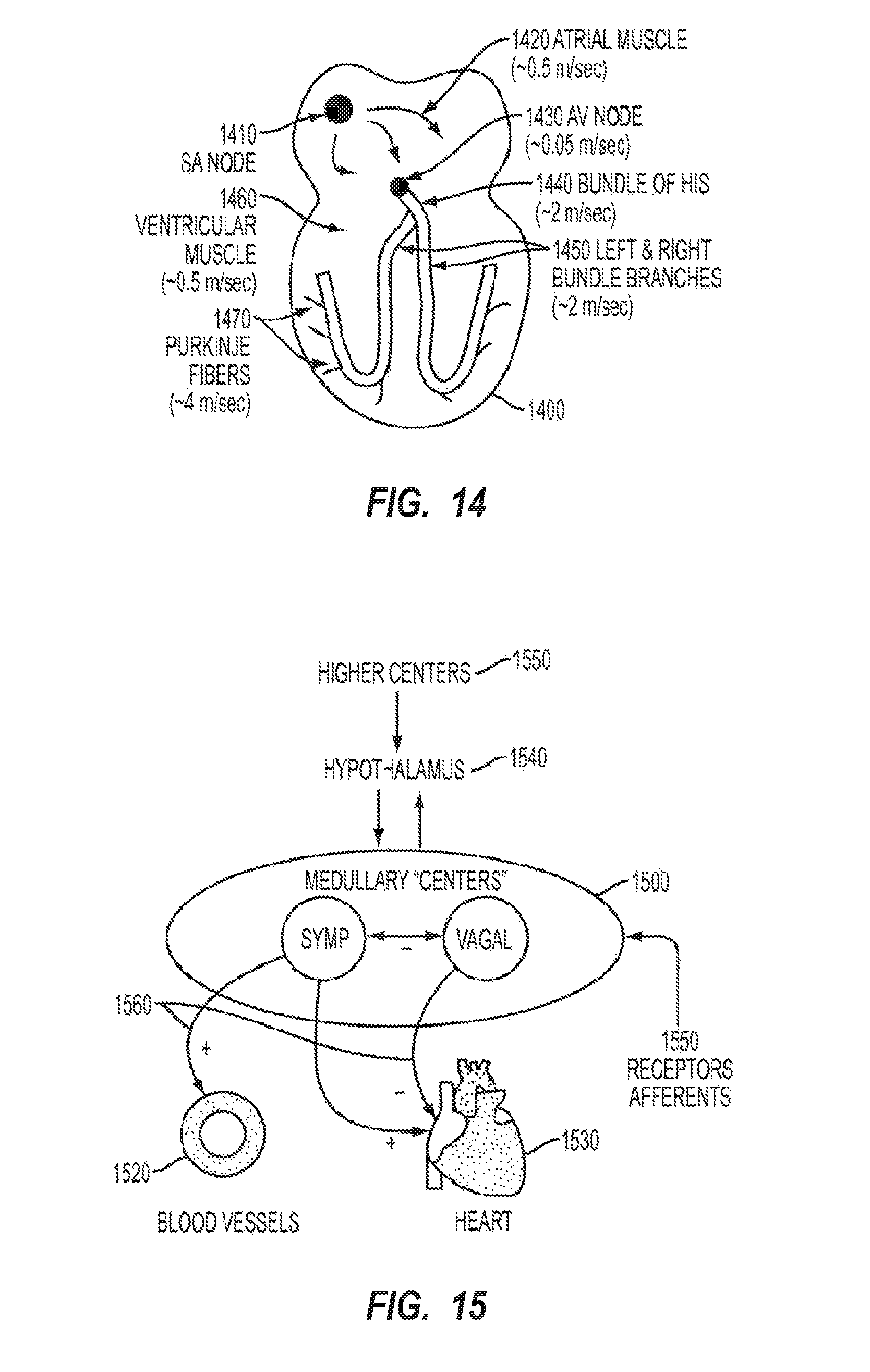
D00015

D00016

D00017

D00018
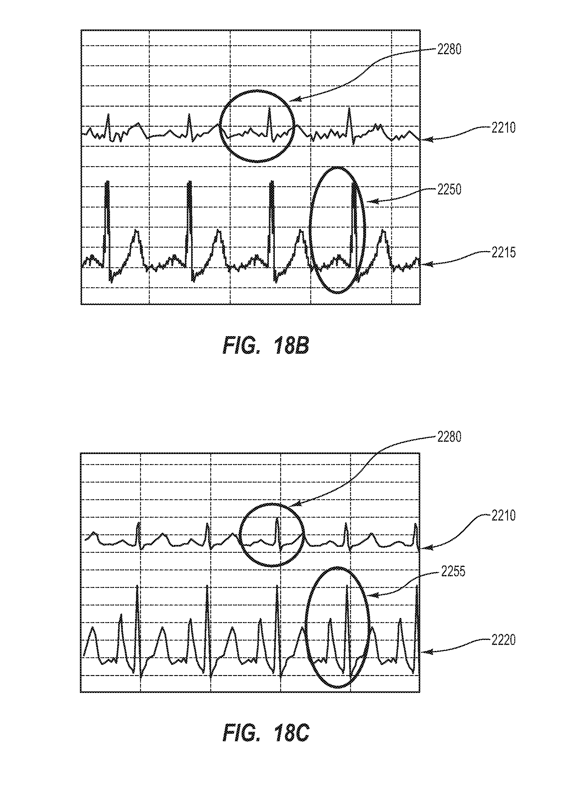
D00019

D00020
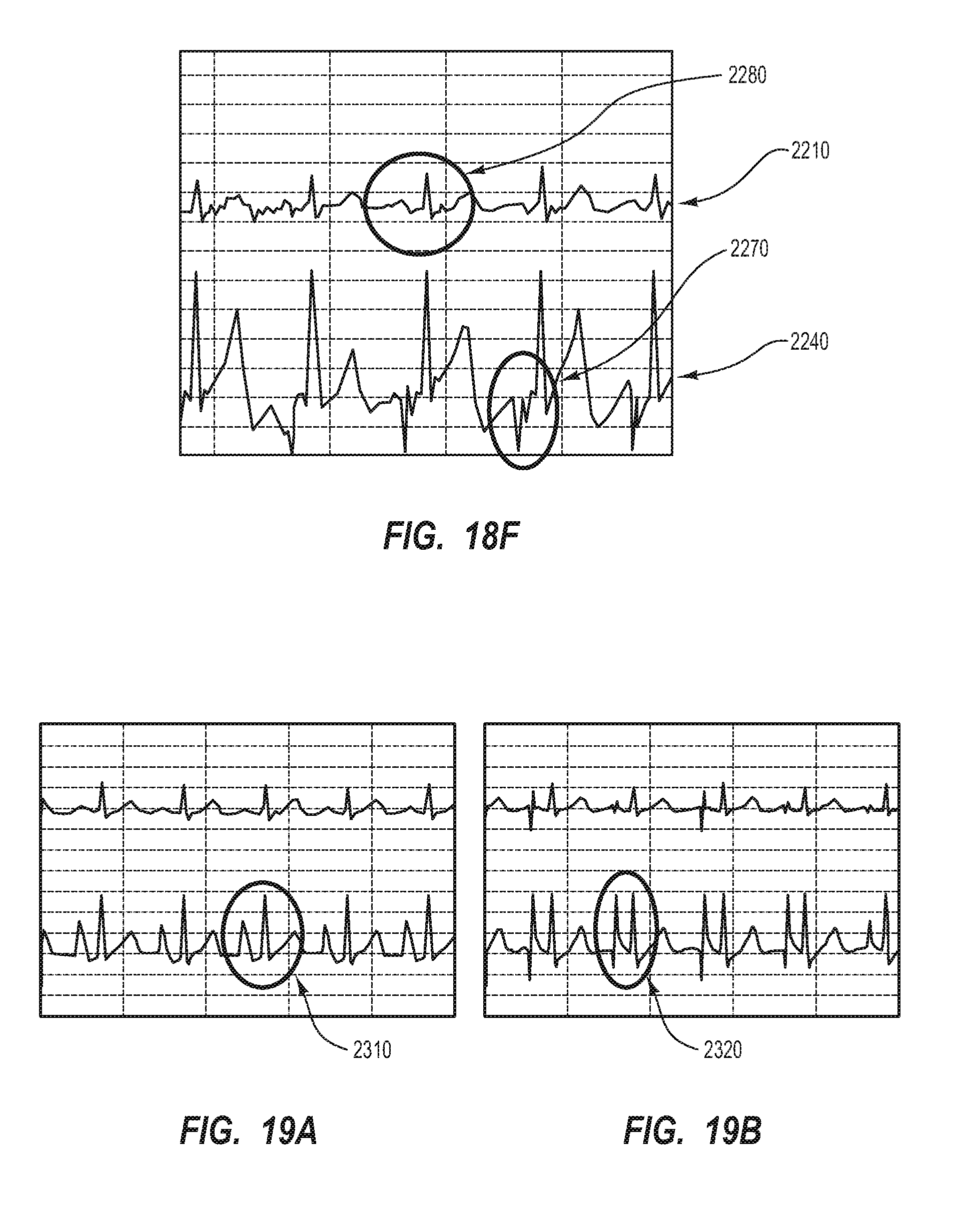
D00021

D00022
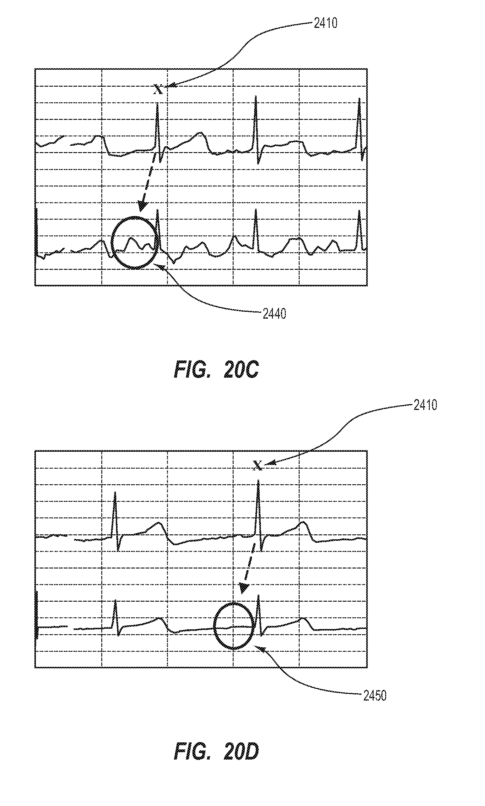
D00023

D00024
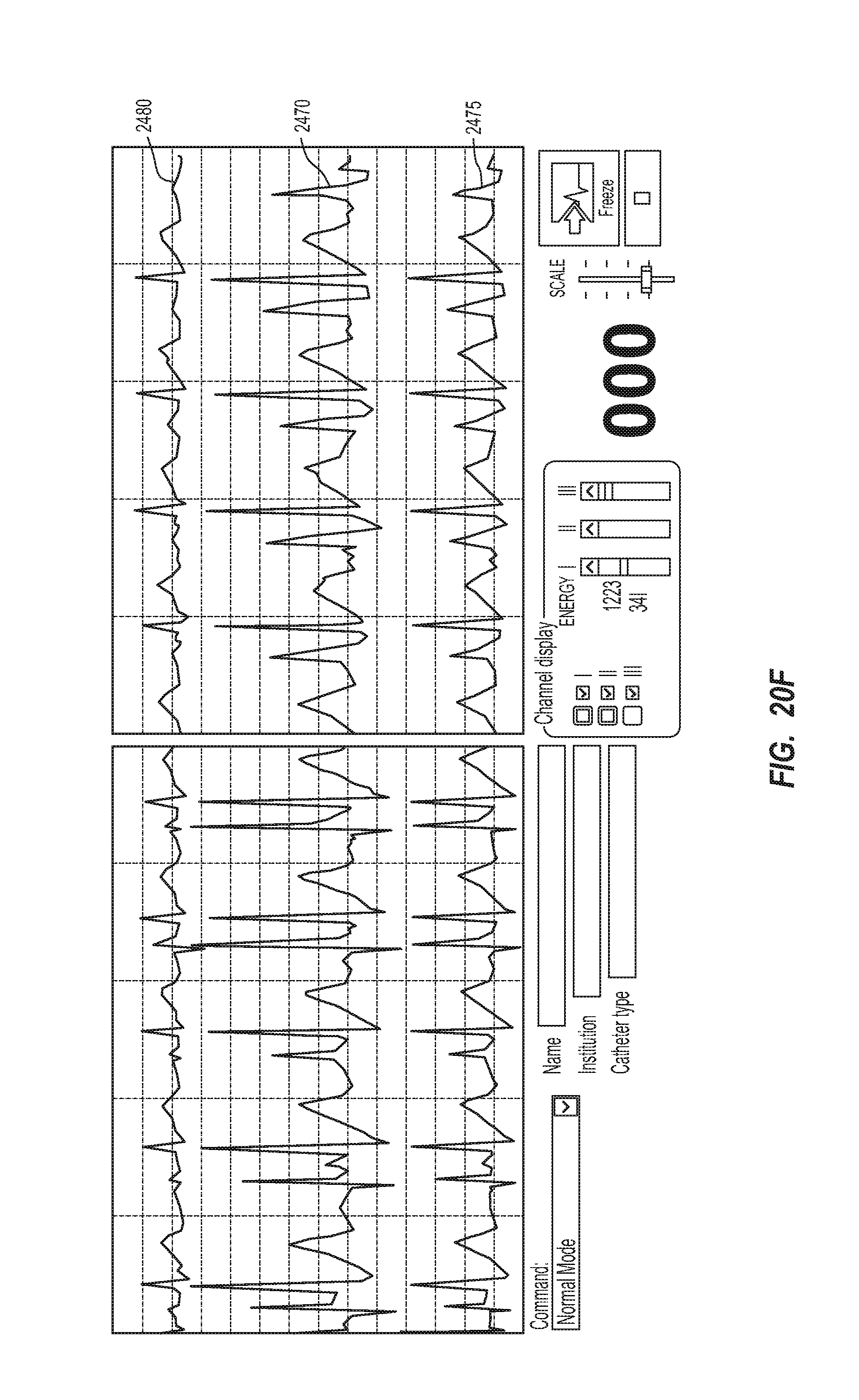
D00025

D00026
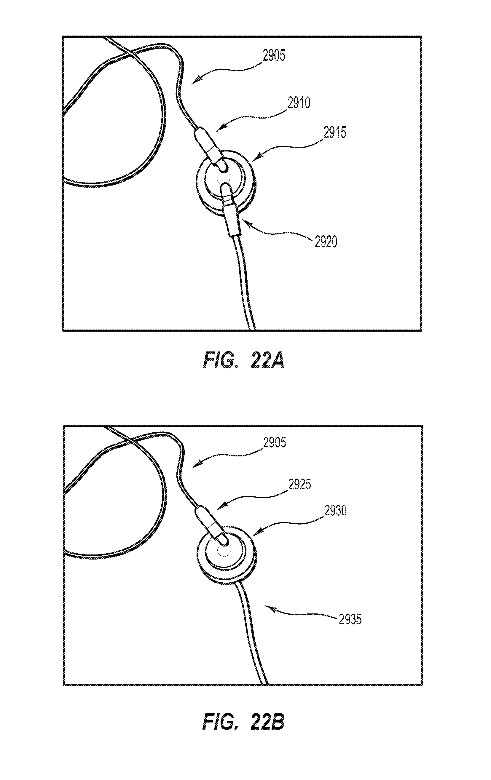
D00027

D00028

D00029

D00030

D00031

D00032

D00033
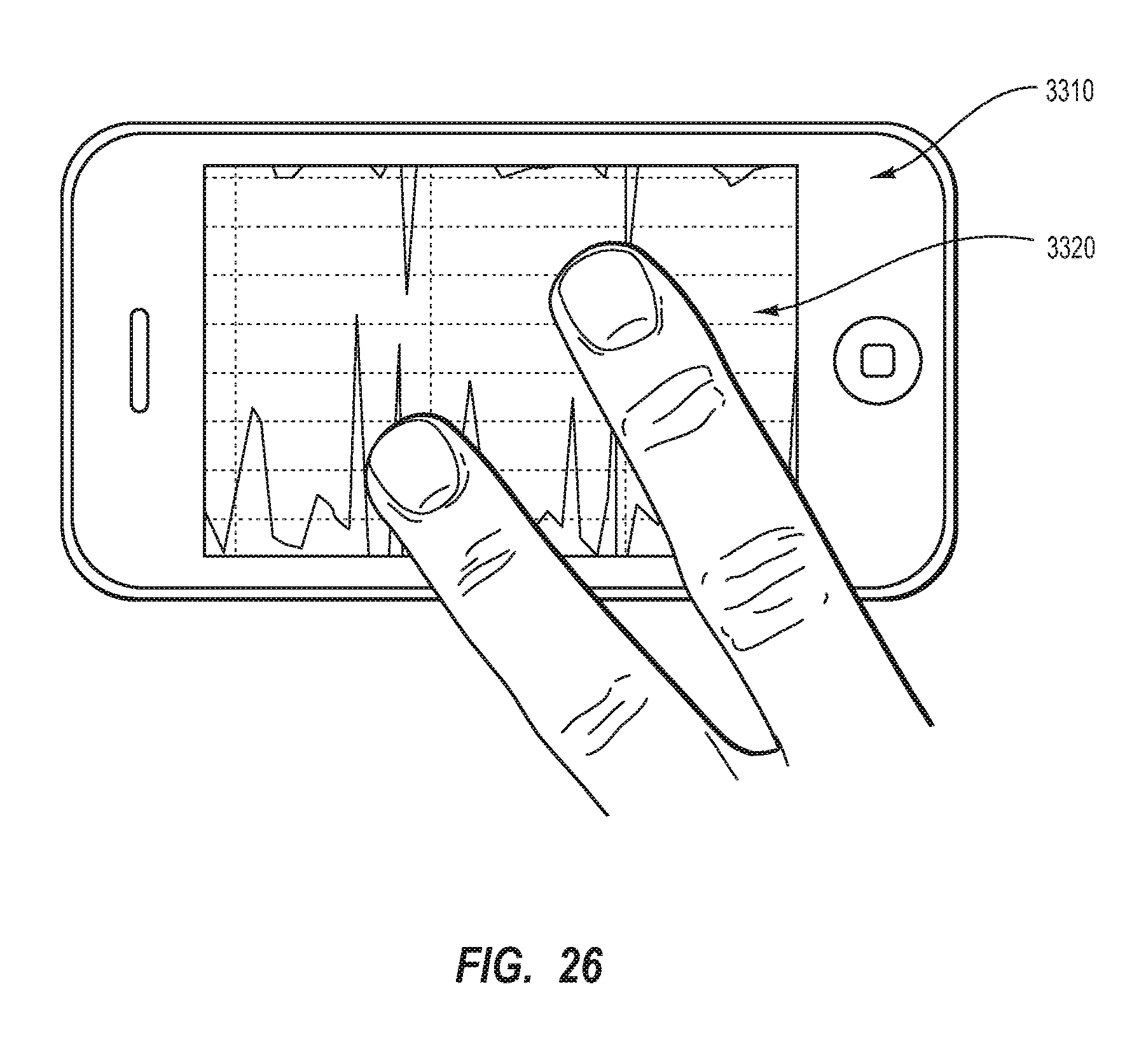
D00034

D00035

D00036

D00037

D00038
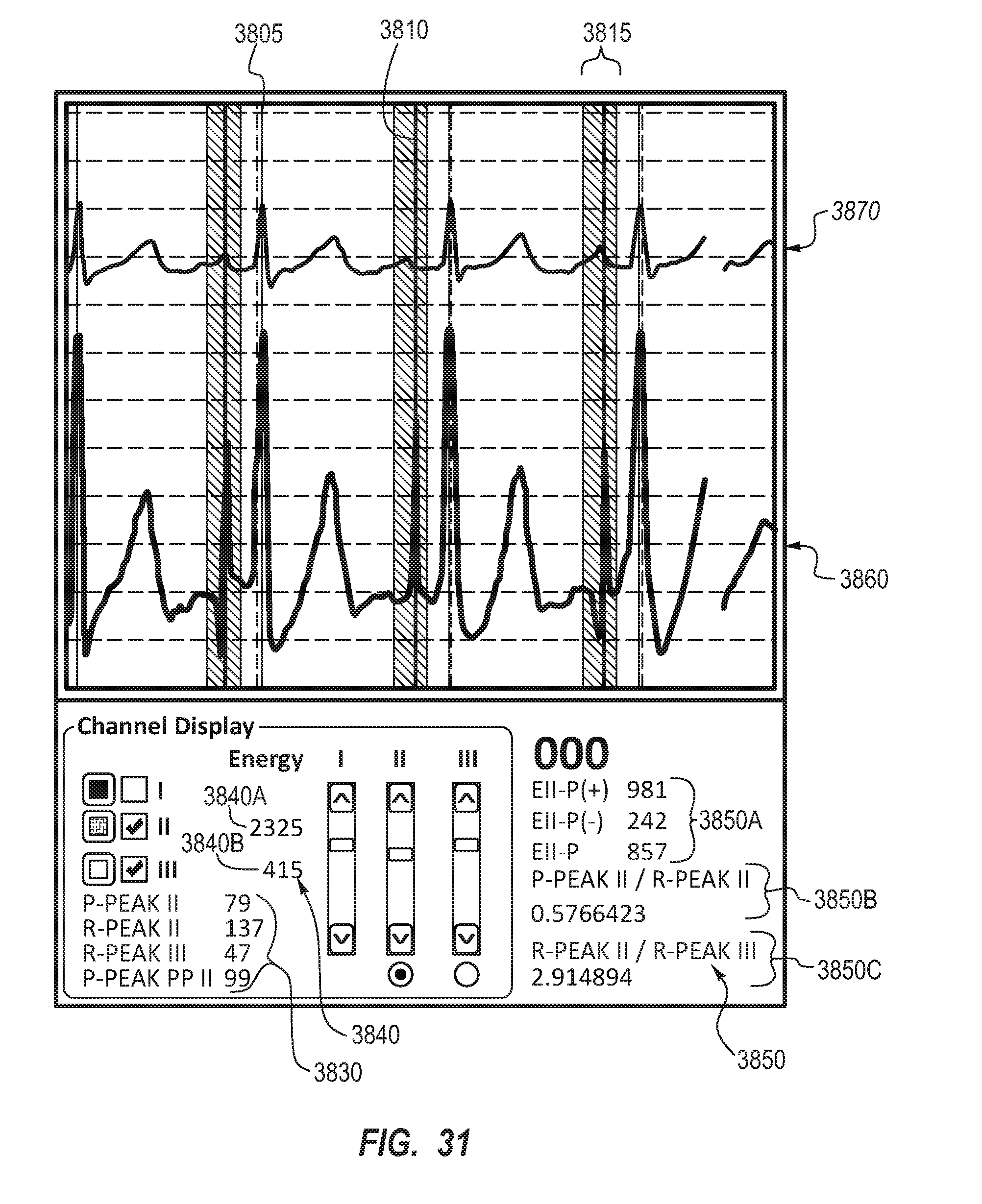
D00039

D00040
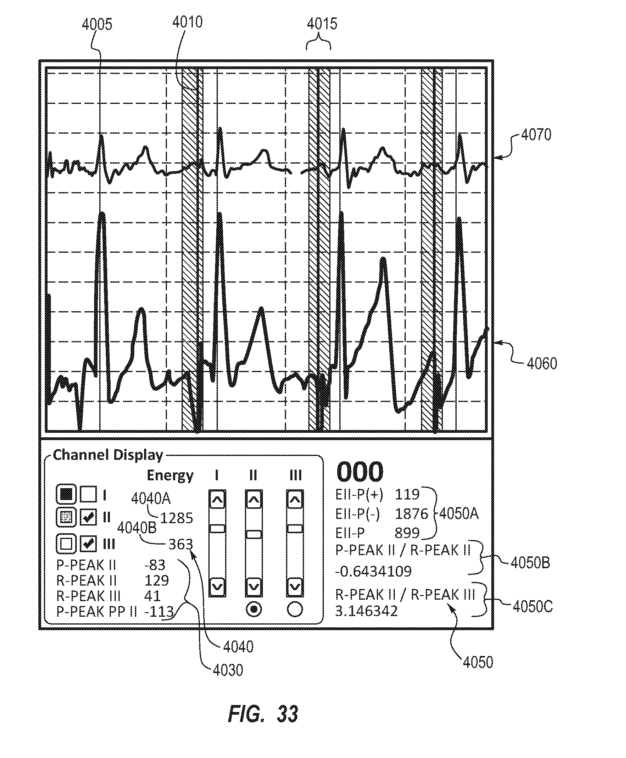
D00041

D00042

D00043

D00044

D00045

D00046

XML
uspto.report is an independent third-party trademark research tool that is not affiliated, endorsed, or sponsored by the United States Patent and Trademark Office (USPTO) or any other governmental organization. The information provided by uspto.report is based on publicly available data at the time of writing and is intended for informational purposes only.
While we strive to provide accurate and up-to-date information, we do not guarantee the accuracy, completeness, reliability, or suitability of the information displayed on this site. The use of this site is at your own risk. Any reliance you place on such information is therefore strictly at your own risk.
All official trademark data, including owner information, should be verified by visiting the official USPTO website at www.uspto.gov. This site is not intended to replace professional legal advice and should not be used as a substitute for consulting with a legal professional who is knowledgeable about trademark law.