Desk with combinative work surfaces
Lin
U.S. patent number 10,271,642 [Application Number 16/109,163] was granted by the patent office on 2019-04-30 for desk with combinative work surfaces. This patent grant is currently assigned to Hi-Max Innovation Co., Ltd., Yi-Chen Tseng. The grantee listed for this patent is HI-MAX INNOVATION CO., LTD., Yi-Chen Tseng. Invention is credited to Jhih-Fan Lin.


View All Diagrams
| United States Patent | 10,271,642 |
| Lin | April 30, 2019 |
Desk with combinative work surfaces
Abstract
A desk includes a base and a plurality of work surface assemblies mounted on the base. The base has a shaft and two stand connected to opposite ends of the shaft. Each of the work surface assemblies has a board and a leg having opposite ends connected to the board and the shaft of the base respectively. The shaft has a plurality of shaft sections connected in series. Whereby a user may pick a predetermined number of shaft sections in serial connection according to a number and a pattern of the work surface assemblies to be mounted on the shaft.
| Inventors: | Lin; Jhih-Fan (Taichung, TW) | ||||||||||
|---|---|---|---|---|---|---|---|---|---|---|---|
| Applicant: |
|
||||||||||
| Assignee: | Tseng; Yi-Chen (Taichung,
TW) Hi-Max Innovation Co., Ltd. (Taichung, TW) |
||||||||||
| Family ID: | 66248114 | ||||||||||
| Appl. No.: | 16/109,163 | ||||||||||
| Filed: | August 22, 2018 |
Related U.S. Patent Documents
| Application Number | Filing Date | Patent Number | Issue Date | ||
|---|---|---|---|---|---|
| 15906692 | Feb 27, 2018 | ||||
| Current U.S. Class: | 1/1 |
| Current CPC Class: | A47B 13/088 (20130101); A47B 13/023 (20130101); A47B 13/003 (20130101); A47B 2013/006 (20130101) |
| Current International Class: | A47B 13/08 (20060101); A47B 13/02 (20060101); A47B 13/00 (20060101) |
| Field of Search: | ;108/64,147.11,147,50.01,150 ;248/159,161 |
References Cited [Referenced By]
U.S. Patent Documents
| 3082712 | March 1963 | Johnson |
| 3339503 | September 1967 | Flodell |
| 3982785 | September 1976 | Ambasz |
| 4679510 | July 1987 | Veyhl |
| 4748913 | June 1988 | Favaretto |
| 5285987 | February 1994 | Gonzalez |
| 5522324 | June 1996 | van Gelder |
| 5794545 | August 1998 | McDaniel |
| 5943966 | August 1999 | Machado |
| 5967631 | October 1999 | Ko |
| 6161487 | December 2000 | Chang |
| 6267064 | July 2001 | Ostertag |
| 6283043 | September 2001 | Stern |
| 6431319 | August 2002 | Myers et al. |
| 6662734 | December 2003 | Chang |
| 6997114 | February 2006 | Chang |
| 7908981 | March 2011 | Agee |
| D719386 | December 2014 | Mueller |
| 8967054 | March 2015 | Henriott |
| 9655445 | May 2017 | Gammon |
| 2005/0274297 | December 2005 | Montague, III |
| 2007/0261614 | November 2007 | Weissenrieder |
| 2008/0289545 | November 2008 | Picchio |
| 2013/0256611 | October 2013 | Ruth sen. |
| 2014/0331903 | November 2014 | Massimini |
| 2014/0360413 | December 2014 | Schenk |
Attorney, Agent or Firm: Wang Law Firm, Inc.
Claims
What is claimed is:
1. A desk, comprising: a base having a shaft and two stands connected to opposite ends of the shaft; and a plurality of work surface assemblies mounted on the base, wherein each of the work surface assemblies has a board and a leg having opposite ends connected to the board and the shaft of the base respectively; wherein the shaft has a plurality of shaft sections removably connected in series; each of the shaft sections has a main body, a protrusion at an end of the main body, and a slot at an opposite end of the main body; a diameter of the slot is greater than an outer diameter of the protrusion, whereby the protrusion of the shaft section is able to be inserted into the slot of another one of the shaft sections to connect the shaft sections in series.
2. The desk of claim 1, wherein the shaft further has a sleeve member; the sleeve member has a hole to be fitted to the protrusion of the shaft section which is not inserted into the slot of the another one of the shaft sections.
3. The desk of claim 2, wherein an outer diameter of the sleeve member is substantially the same as an outer diameter of the main body of the shaft section.
4. The desk of claim 2, wherein the each of the stands has a bore; the opposite ends of the shaft are received in the bores of the stands respectively; and the sleeve member is received in the bore of one of the stands.
5. The desk of claim 1, wherein an overlapped portion is formed at a portion of the shaft where the protrusion of the shaft section is inserted into the slot of another one of the shaft sections, and the leg of the work surface assembly is connected to the overlapped portion.
6. The desk of claim 5, wherein the leg is provided with a connecting plate, and the connecting plate is fixed to the overlapped portion of the shaft.
7. The desk of claim 6, further comprising a fastener securing the connecting plate to the main body and the protrusion at the overlapped portion.
Description
BACKGROUND OF THE INVENTION
1. Technical Field
The present invention relates to a desk or a table, and more particularly to a desk with combinative work surfaces.
2. Description of Related Art
Typically, a conventional height adjustable desk has a work surface with a telescopic leg. For example, US 20130256611 and U.S. Pat. No. 6,431,319 provided a height adjustable desk with a scissor for lifting a work surface. U.S. Pat. No. 8,001,909 provided a lifting column for lifting a work surface.
These conventional height adjustable desks only provided a height adjustable work surface. There is no such a prior art, which have plural of adjustable work surfaces to be selected for combination. It may be a solution to have several desks for connection in a matrix. However, it takes a large space for sure. Besides, the complex structure may make it difficult to sit.
BRIEF SUMMARY OF THE INVENTION
In view of the above, the primary objective of the present invention is to provide a desk with combinative work surfaces, which has simple structure and takes less space.
In order to achieve the objective of the present invention, a desk includes a base and a plurality of work surface assemblies mounted on the base. The base has a shaft and two stand connected to opposite ends of the shaft. Each of the work surface assemblies has a board and a leg having opposite ends connected to the board and the shaft of the base respectively. The shaft has a plurality of shaft sections connected in series. Each of the shaft sections has main body, a protrusion at an end of the main body, and a slot at an opposite end of the main body. A diameter of the slot is greater than an outer diameter of the protrusion, whereby the protrusion of the shaft section is able to be inserted into the slot of another one of the shaft sections to connect the shaft sections in series.
Whereby a user may pick a predetermined number of shaft section in serial connection according to a number and a pattern of the work surface assemblies to be mounted on the shaft.
BRIEF DESCRIPTION OF THE SEVERAL VIEWS OF THE DRAWINGS
The present invention will be best understood by referring to the following detailed description of some illustrative embodiments in conjunction with the accompanying drawings, in which
FIG. 1 is a perspective view of a first preferred embodiment of the present invention;
FIG. 2 is a perspective view of a second preferred embodiment of the present invention;
FIG. 3 is a perspective view of a third preferred embodiment of the present invention, showing the work surface being lifted;
FIG. 4 is a perspective diagram of a fourth preferred embodiment of the present invention;
FIG. 5 is another perspective view of the second preferred embodiments of the present invention;
FIG. 6 is another perspective view of the third preferred embodiment of the present invention, showing three work surface assemblies being mounted;
FIG. 7 is a right view of the third preferred embodiment of the present invention;
FIG. 8 is a sketch diagram of the preferred embodiment of the present invention, showing users sitting by the desk;
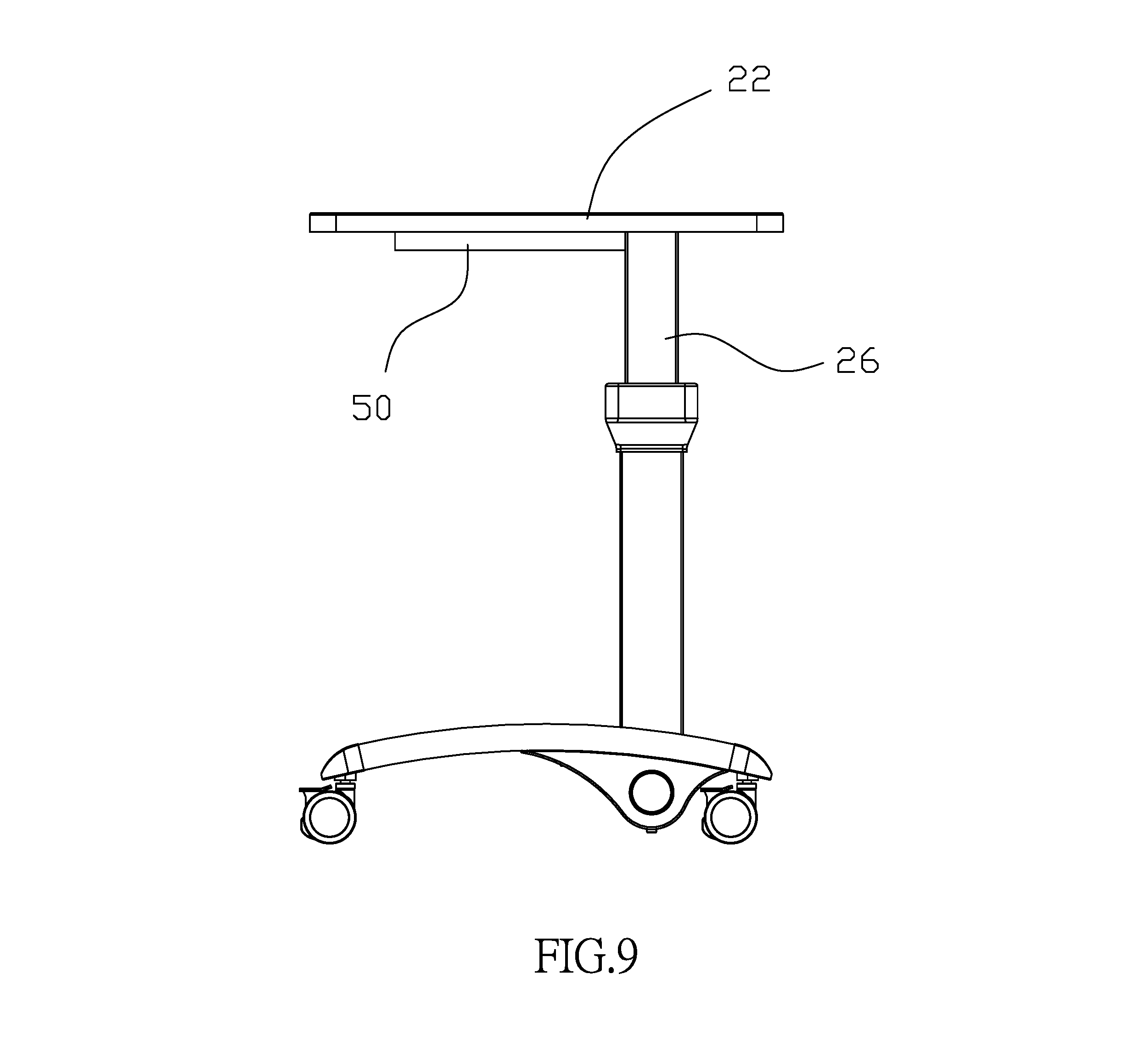
FIG. 9 is a right view of a fifth preferred embodiment of the present invention;
FIG. 10 is an exploded view of a sixth preferred embodiment of the present invention;
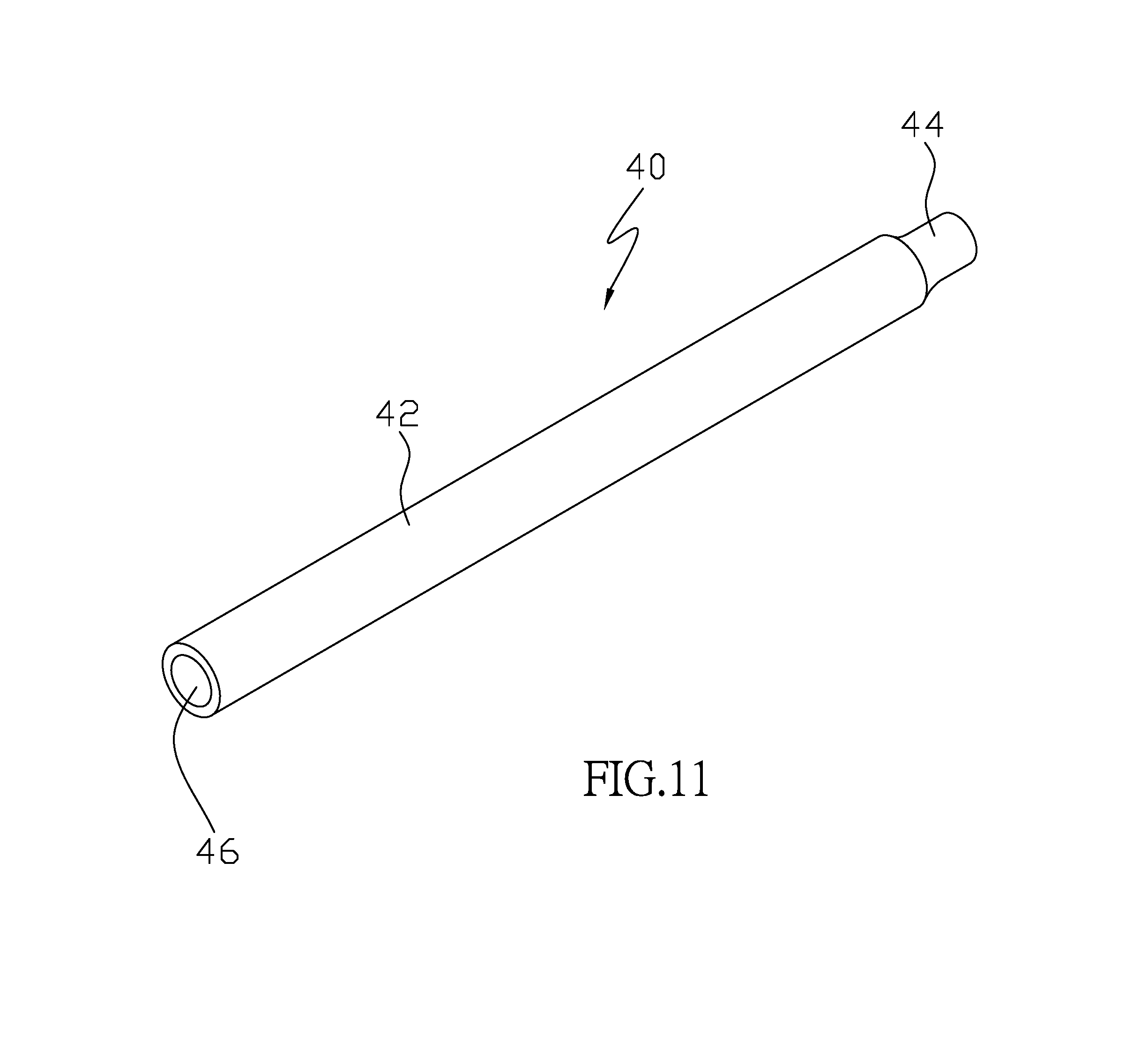
FIG. 11 is a perspective view of the shaft section of the sixth preferred embodiment of the present invention; and
FIG. 12 is a perspective view of the shaft section of the sixth preferred embodiment of the present invention.
DETAILED DESCRIPTION OF THE INVENTION
FIG. 1 shows a desk of the first preferred embodiment of the present invention, includes a base 10 and two work surface assemblies 20. The base 10, referring to FIG. 5 and FIG. 6, includes a shaft 12 and two stands 14 connected to opposite ends of the shaft 12. Each of the stands 14 is provided with two wheels 16. Each of the work surface assembly 20 includes a leg 24 and a board 22 connected to an end of the leg 24. The leg 24 has an opposite end connected to the shaft 12 of the base 10. The leg 24 has an inner tube 26, and the inner tube 26 has an inclined section 29 and a straight section 27 (FIG. 7). The leg 24 further has an outer tube 28, in which the straight section 27 of the inner tube 26 is inserted. The inner tube 26 is controllable to be moved relative to the outer tube 28. The inclined section 29 of the inner tube 26 is left out of the outer tube 28 and connected to a bottom of the board 22. In an embodiment, a pneumatic device (not shown) is mounted in the leg 24, so that the combination of the inner and the outer tubes 26, 28 and the pneumatic device work as a gas spring to lift or lower the board 22. It is noted that the board 22 may be lifted and lowered by manual operation or by electrical control.
The same structure may provide the desk of the present invention with more work surface assemblies. For example, FIG. 2 shows the desk of the second preferred embodiment of the present invention having three work surface assemblies 20 arranged in a row. In this matter, the inclined sections 29 of the inner tubes 24 of the work surface assemblies 20 lean toward the same direction (referring to FIG. 5). FIG. 3 shows the desk of the third preferred embodiment of the present invention having four work surface assemblies 20 arranged in two rows. In this matter, the inclined sections 29 of the boards 22 in the same column lean to opposite directions, and the outer tubes 28 arranged in a row (referring to FIG. 6). The same as above, FIG. 4 shows the desk of the fourth preferred embodiment of the present invention having six work surface assemblies 20 arranged in two rows.
Since the shaft 12 is straight, in spite of the boards 22 of the work surface assemblies 20 being arranged in one row or in two rows, the outer tubes 28 (or the straight sections 27) are lined in a row.
As shown in FIG. 7, the board 22 has a first end 30 and a second end 32 opposite to the first end 30. A distance (d) between the second end 32 and the outer tube 28 (or the straight section 27) is greater than a distance (D) between the first end 30 and the outer tube 28 (or the straight section 27).
As shown in FIG. 8, the first end 30 is designated to an end proximal to a person who sits by the desk of the present invention. Therefore, the desk of the present invention provides a large space under the board for legs of a person who sits by the desk. In addition, the inclined section 29 of the inner tube 26 is connected to a center of weight of the board, or close to the center of weight which provides the desk with a stable condition.
It is easy to understand that the present invention only provides a base, on which may mount one or more work surface assemblies in in a matrix of a row or two rows. It has a simple structure and takes less space. The height of the board 22 is adjustable to meet a height of a person who sits by the desk.
FIG. 9 shows a desk of the fifth preferred embodiment of the present invention, which is similar to above preferred embodiment, except that the leg 26 has a straight section only. In the fifth preferred embodiment, the leg 26 further has a reinforced rib 50 connected to the board 22.
As shown in FIG. 10, a desk of the sixth preferred embodiment of the present invention includes a base 10 and three work surface assemblies 20. The work surface assemblies 20 are the same as the above embodiments, so we do not describe the detail here. The base 10 includes a shaft 12 and two stands 14 connected to opposite ends of the shaft 12. The different part of the base 10 is that the shaft 12 has a plurality of shaft sections 40 and a sleeve member 50 connected in series.
As shown in FIG. 11, each of the shaft sections 40 has a main body 42, a protrusion 44 at an end of the main body 42, and a slot 46 at an opposite end of the main body 42. Precisely, the protrusion 44 is a shrunk portion of the main body 42, having an outer diameter smaller than an outer diameter of the main body 42 and a diameter of the slot 46. As a result, the protrusion 44 of the shaft section 40 is able to be inserted into the slot 46 of another shaft section 40 to connect the shaft sections 40 in series to form the shaft 12. It is noted that an overlapped portion 48 is defined at a portion of the protrusion 44 engaging the slot 46 of two connected shaft sections 40.
The sleeve member 50 is a ring-like member, having a hole at a center thereof. The sleeve member 50 has an outer diameter equal to the outer diameter of the main body 42 and an inner diameter slightly greater than outer diameter of protrusion. The sleeve member 50 is fitted to the protrusion 44 of the shaft sections 40, which is not inserted into the slot 46 of another shaft section 40. As a result, the shaft 12 has a constant outer diameter.
As shown in FIG. 12, each of the stands 14 has a bore 52, and opposite ends of the shaft 12 are received in the bores 52 of the stands 14 respectively. Precisely, the sleeve member 50 is received in the bore 52 of the stand 14. Because of the sleeve member 50, the entire shaft 12 has a constant outer diameter, so that the bores 52 of the stands 14 have the same diameters. Besides, connecting plates 54, which are fixed to the legs 24 of the work surface assemblies 20, are connected to the overlapped portions 48 of the shaft sections 40. Fasteners 56, such as bolts or screws, are provided to secure the connecting plate 54 to the main body 42 and the protrusion 44 of the connected shaft sections 40 in the overlapped portion 48.
In conclusion, the user may connect the shaft sections 40 to obtain the shaft with a predetermined length according to the number and pattern of the work surface assemblies 20. For example, it needs three shaft sections 40 for the desk of the first preferred embodiment (FIG. 1), four shaft sections 40 are needed for the desk of the second preferred embodiment (FIG. 2), three shaft sections 40 are needed for the desk of the third preferred embodiment (FIG. 3), and four shaft sections 40 are needed for the desk of the fourth preferred embodiment (FIG. 4).
It must be pointed out that the embodiments described above are only some preferred embodiments of the present invention. All equivalent structures which employ the concepts disclosed in this specification and the appended claims should fall within the scope of the present invention.
* * * * *
D00000
D00001
D00002
D00003
D00004
D00005
D00006
D00007
D00008
D00009
D00010
D00011
D00012

XML
uspto.report is an independent third-party trademark research tool that is not affiliated, endorsed, or sponsored by the United States Patent and Trademark Office (USPTO) or any other governmental organization. The information provided by uspto.report is based on publicly available data at the time of writing and is intended for informational purposes only.
While we strive to provide accurate and up-to-date information, we do not guarantee the accuracy, completeness, reliability, or suitability of the information displayed on this site. The use of this site is at your own risk. Any reliance you place on such information is therefore strictly at your own risk.
All official trademark data, including owner information, should be verified by visiting the official USPTO website at www.uspto.gov. This site is not intended to replace professional legal advice and should not be used as a substitute for consulting with a legal professional who is knowledgeable about trademark law.