Redundant array of independent discs and dispersed storage network system re-director
Grube , et al.
U.S. patent number 10,268,374 [Application Number 15/276,903] was granted by the patent office on 2019-04-23 for redundant array of independent discs and dispersed storage network system re-director. This patent grant is currently assigned to International Business Machines Corporation. The grantee listed for this patent is International Business Machines Corporation. Invention is credited to Gary W. Grube, Jason K. Resch.


| United States Patent | 10,268,374 |
| Grube , et al. | April 23, 2019 |
Redundant array of independent discs and dispersed storage network system re-director
Abstract
Systems and method for accessing data in a storage network include a processing module receives redundant array of independent disks (RAID) data to store determining which memories to utilize (e.g., a RAID memory, local and/or remote dispersed storage network (DSN) memory) based on one or more of the metadata, the RAID data, a vault lookup, a command, a message, a performance indicator, a predetermination, local DSN memory capabilities, remote DSN memory capabilities, RAID memory capabilities, and a comparison of requirements to capabilities of the RAID memory and local and/or DSN memory. The processing module saves the determination choice in a memory indicator that is stored in one or more of the RAID memory, the local DSN memory, the remote DSN memory, and a DSN user vault.
| Inventors: | Grube; Gary W. (Barrington Hills, IL), Resch; Jason K. (Chicago, IL) | ||||||||||
|---|---|---|---|---|---|---|---|---|---|---|---|
| Applicant: |
|
||||||||||
| Assignee: | International Business Machines
Corporation (Armonk, NY) |
||||||||||
| Family ID: | 57775018 | ||||||||||
| Appl. No.: | 15/276,903 | ||||||||||
| Filed: | September 27, 2016 |
Prior Publication Data
| Document Identifier | Publication Date | |
|---|---|---|
| US 20170017401 A1 | Jan 19, 2017 | |
Related U.S. Patent Documents
| Application Number | Filing Date | Patent Number | Issue Date | ||
|---|---|---|---|---|---|
| 15095637 | Apr 11, 2016 | 10049008 | |||
| 12983226 | Apr 12, 2016 | 9311184 | |||
| 61314166 | Mar 16, 2010 | ||||
| 61308938 | Feb 27, 2010 | ||||
| Current U.S. Class: | 1/1 |
| Current CPC Class: | G06F 11/0727 (20130101); G06F 3/0647 (20130101); G06F 3/0689 (20130101); G06F 3/0685 (20130101); G06F 3/0631 (20130101); H04L 67/1097 (20130101); G06F 3/065 (20130101); G06F 3/067 (20130101); G06F 3/0665 (20130101); G06F 3/068 (20130101); G06F 3/0619 (20130101); G06F 3/0614 (20130101); G06F 3/0604 (20130101); G06F 11/1076 (20130101); G06F 11/1461 (20130101); G06F 11/1456 (20130101); G06F 2211/1028 (20130101) |
| Current International Class: | G06F 11/00 (20060101); H04L 29/08 (20060101); G06F 3/06 (20060101); G06F 11/10 (20060101); G06F 11/07 (20060101) |
References Cited [Referenced By]
U.S. Patent Documents
| 4092732 | May 1978 | Ouchi |
| 5454101 | September 1995 | Mackay et al. |
| 5485474 | January 1996 | Rabin |
| 5774643 | June 1998 | Lubbers et al. |
| 5802364 | September 1998 | Senator et al. |
| 5809285 | September 1998 | Hilland |
| 5890156 | March 1999 | Rekieta et al. |
| 5987622 | November 1999 | Lo Verso et al. |
| 5991414 | November 1999 | Garay et al. |
| 6012159 | January 2000 | Fischer et al. |
| 6058454 | May 2000 | Gerlach et al. |
| 6128277 | October 2000 | Bruck et al. |
| 6175571 | January 2001 | Haddock et al. |
| 6192472 | February 2001 | Garay et al. |
| 6256688 | July 2001 | Suetaka et al. |
| 6272658 | August 2001 | Steele et al. |
| 6301604 | October 2001 | Nojima |
| 6356949 | March 2002 | Katsandres et al. |
| 6366995 | April 2002 | Vilkov et al. |
| 6374336 | April 2002 | Peters et al. |
| 6415373 | July 2002 | Peters et al. |
| 6418539 | July 2002 | Walker |
| 6449688 | September 2002 | Peters et al. |
| 6567948 | May 2003 | Steele et al. |
| 6571282 | May 2003 | Bowman-Amuah |
| 6609223 | August 2003 | Wolfgang |
| 6718361 | April 2004 | Basani et al. |
| 6760808 | July 2004 | Peters et al. |
| 6785768 | August 2004 | Peters et al. |
| 6785783 | August 2004 | Buckland |
| 6826711 | November 2004 | Moulton et al. |
| 6879596 | April 2005 | Dooply |
| 7003688 | February 2006 | Pittelkow et al. |
| 7024451 | April 2006 | Jorgenson |
| 7024609 | April 2006 | Wolfgang et al. |
| 7080101 | July 2006 | Watson et al. |
| 7103824 | September 2006 | Halford |
| 7103915 | September 2006 | Redlich et al. |
| 7111115 | September 2006 | Peters et al. |
| 7140044 | November 2006 | Redlich et al. |
| 7146644 | December 2006 | Redlich et al. |
| 7171493 | January 2007 | Shu et al. |
| 7222133 | May 2007 | Raipurkar et al. |
| 7240236 | July 2007 | Cutts et al. |
| 7272613 | September 2007 | Sim et al. |
| 7636724 | December 2009 | de la Torre et al. |
| 2002/0062422 | May 2002 | Butterworth et al. |
| 2002/0166079 | November 2002 | Ulrich et al. |
| 2003/0018927 | January 2003 | Gadir et al. |
| 2003/0037261 | February 2003 | Meffert et al. |
| 2003/0065617 | April 2003 | Watkins et al. |
| 2003/0084020 | May 2003 | Shu |
| 2004/0024963 | February 2004 | Talagala et al. |
| 2004/0122917 | June 2004 | Menon et al. |
| 2004/0123223 | June 2004 | Halford |
| 2004/0215998 | October 2004 | Buxton et al. |
| 2004/0228493 | November 2004 | Ma et al. |
| 2005/0100022 | May 2005 | Ramprashad |
| 2005/0114594 | May 2005 | Corbett et al. |
| 2005/0125593 | June 2005 | Karpoff et al. |
| 2005/0131993 | June 2005 | Fatula, Jr. |
| 2005/0132070 | June 2005 | Redlich et al. |
| 2005/0144382 | June 2005 | Schmisseur |
| 2005/0229069 | October 2005 | Hassner |
| 2006/0047907 | March 2006 | Shiga et al. |
| 2006/0136448 | June 2006 | Cialini et al. |
| 2006/0156059 | July 2006 | Kitamura |
| 2006/0224603 | October 2006 | Correll, Jr. |
| 2007/0079081 | April 2007 | Gladwin et al. |
| 2007/0079082 | April 2007 | Gladwin et al. |
| 2007/0079083 | April 2007 | Gladwin et al. |
| 2007/0088970 | April 2007 | Buxton et al. |
| 2007/0174192 | July 2007 | Gladwin et al. |
| 2007/0214285 | September 2007 | Au et al. |
| 2007/0234110 | October 2007 | Soran et al. |
| 2007/0283167 | December 2007 | Venters, III et al. |
| 2008/0065827 | March 2008 | Byrne |
| 2009/0094251 | April 2009 | Gladwin et al. |
| 2009/0094318 | April 2009 | Gladwin et al. |
| 2010/0023524 | January 2010 | Gladwin et al. |
| 2010/0266119 | October 2010 | Leggette |
| 2010/0266120 | October 2010 | Leggette |
| 2010/0268692 | October 2010 | Resch |
| 2010/0268877 | October 2010 | Resch |
| 2010/0268938 | October 2010 | Resch |
| 2010/0268966 | October 2010 | Leggette |
| 2010/0269008 | October 2010 | Leggette |
| 2011/0213929 | September 2011 | Baptist |
Other References
|
Shamir; How to Share a Secret; Communications of the ACM; vol. 22, No. 11; Nov. 1979; pp. 612-613. cited by applicant . Rabin; Efficient Dispersal of Information for Security, Load Balancing, and Fault Tolerance; Journal of the Association for Computer Machinery; vol. 36, No. 2; Apr. 1989; pp. 335-348. cited by applicant . Chung; An Automatic Data Segmentation Method for 3D Measured Data Points; National Taiwan University; pp. 1-8; 1998. cited by applicant . Plank, T1: Erasure Codes for Storage Applications; FAST2005, 4th Usenix Conference on File Storage Technologies; Dec. 13-16, 2005; pp. 1-74. cited by applicant . Wildi; Java iSCSi Initiator; Master Thesis; Department of Computer and Information Science, University of Konstanz; Feb. 2007; 60 pgs. cited by applicant . Legg; Lightweight Directory Access Protocol (LDAP): Syntaxes and Matching Rules; IETF Network Working Group; RFC 4517; Jun. 2006; pp. 1-50. cited by applicant . Zeilenga; Lightweight Directory Access Protocol (LDAP): Internationalized String Preparation; IETF Network Working Group; RFC 4518; Jun. 2006; pp. 1-14. cited by applicant . Smith; Lightweight Directory Access Protocol (LDAP): Uniform Resource Locator; IETF Network Working Group; RFC 4516; Jun. 2006; pp. 1-15. cited by applicant . Smith; Lightweight Directory Access Protocol (LDAP): String Representation of Search Filters; IETF Network Working Group; RFC 4515; Jun. 2006; pp. 1-12. cited by applicant . Zeilenga; Lightweight Directory Access Protocol (LDAP): Directory Information Models; IETF Network Working Group; RFC 4512; Jun. 2006; pp. 1-49. cited by applicant . Sciberras; Lightweight Directory Access Protocol (LDAP): Schema for User Applications; IETF Network Working Group; RFC 4519; Jun. 2006; pp. 1-33. cited by applicant . Harrison; Lightweight Directory Access Protocol (LDAP): Authentication Methods and Security Mechanisms; IETF Network Working Group; RFC 4513; Jun. 2006; pp. 1-32. cited by applicant . Zeilenga; Lightweight Directory Access Protocol (LDAP): Technical Specification Road Map; IETF Network Working Group; RFC 4510; Jun. 2006; pp. 1-8. cited by applicant . Zeilenga; Lightweight Directory Access Protocol (LDAP): String Representation of Distinguished Names; IETF Network Working Group; RFC 4514; Jun. 2006; pp. 1-15. cited by applicant . Sermersheim; Lightweight Directory Access Protocol (LDAP): The Protocol; IETF Network Working Group; RFC 4511; Jun. 2006; pp. 1-68. cited by applicant . Satran, et al.; Internet Small Computer Systems Interface (iSCSI); IETF Network Working Group; RFC 3720; Apr. 2004; pp. 1-257. cited by applicant . Xin, et al.; Evaluation of Distributed Recovery in Large-Scale Storage Systems; 13th IEEE International Symposium on High Performance Distributed Computing; Jun. 2004; pp. 172-181. cited by applicant . Kubiatowicz, et al.; OceanStore: An Architecture for Global-Scale Persistent Storage; Proceedings of the Ninth International Conference on Architectural Support for Programming Languages and Operating Systems (ASPLOS 2000); Nov. 2000; pp. 1-12. cited by applicant. |
Primary Examiner: Bonzo; Bryce P
Assistant Examiner: Arcos; Jeison C
Attorney, Agent or Firm: Garlick & Markison Markison; Timothy W. Tyson, Jr.; Harry S.
Parent Case Text
CROSS REFERENCE TO RELATED APPLICATIONS
The present U.S. Utility Patent Application claims priority pursuant to 35 U.S.C. .sctn. 120 as a continuation-in-part of U.S. Utility application Ser. No. 15/095,637, entitled "STORING RAID DATA AS ENCODED DATA SLICES IN A DISPERSED STORAGE NETWORK", filed Apr. 11, 2016, which is a continuation of U.S. Utility application Ser. No. 12/983,226, entitled "STORING RAID DATA AS ENCODED DATA SLICES IN A DISPERSED STORAGE NETWORK", filed Dec. 31, 2010, now U.S. Pat. No. 9,311,184, issued on Apr. 12, 2016, which claims priority pursuant to 35 U.S.C. .sctn. 119(e) to U.S. Provisional Application No. 61/308,938, entitled "MULTIPLE MEMORY TYPE STORAGE SYSTEM", filed Feb. 27, 2010; and U.S. Provisional Application No. 61/314,166, entitled "STORAGE AND RETRIEVAL IN A DISTRIBUTED STORAGE SYSTEM", filed Mar. 16, 2010, all of which are hereby incorporated herein by reference in their entirety and made part of the present U.S. Utility Patent Application for all purposes.
Claims
What is claimed is:
1. A method for accessing data in a storage network, the storage network including a redundant array of independent disk (RAID) memory and at least one dispersed storage network (DSN) memory, the method comprises: determining, based at least in part on metadata associated with first RAID data, whether to process the first RAID data using the RAID memory, the at least one DSN memory, or a combination of the RAID memory and the at least one DSN memory and producing a determination; and processing the first RAID data using the RAID memory, the at least one DSN memory, or a combination of the RAID memory and the at least one DSN memory based on the determination.
2. The method of claim 1, wherein processing the first RAID data using the RAID memory, the at least one DSN memory, or a combination of the RAID memory and the at least one DSN memory based on the determination further includes forwarding the first RAID data to, and retrieving the first RAID data from, the RAID memory, and storing selected second RAID data of the first RAID data in the at least one DSN memory.
3. The method of claim 2, wherein the selected second RAID data is selected based on a retrieval frequency of the selected second RAID data.
4. The method of claim 2, wherein determining whether to process first RAID data using the RAID memory, the at least one DSN memory, or a combination of the RAID memory and the at least one DSN memory and producing a determination occurs in response to one or more of an attempt to store the first RAID data in the RAID memory and a background task.
5. The method of claim 2, wherein processing the first RAID data using the RAID memory the at least one DSN memory, or a combination of the RAID memory and the at least one DSN memory based on the determination further includes retrieving the selected second RAID data from the at least one DSN memory to rebuild the first RAID data.
6. The method of claim 1, wherein determining whether to process first RAID data using the RAID memory, the at least one DSN memory, or a combination of the RAID memory and the at least one DSN memory, is further based on one or more of: the first RAID data, a vault lookup, a command, a message, a performance indicator, a predetermination, memory capabilities of the at least one DSN memory, memory capabilities of the RAID memory, or a comparison of requirements to capabilities of the RAID memory to the at least one DSN memory.
7. The method of claim 6, wherein the at least one DSN memory includes a local DSN memory and a remote DSN memory.
8. The method of claim 1, wherein the metadata includes at least one of: a user ID, a data type, a data object name, an expected access frequency, a requirement for priority, a requirement for security, a requirement for performance, or a requirement for when to backup based on access frequency.
9. The method of claim 1, wherein processing the first RAID data using the RAID memory the at least one DSN memory, or a combination of the RAID memory and the at least one DSN memory based on the determination further includes storing the first RAID data in the RAID memory and backing up the first RAID data from the RAID memory to the at least one DSN memory.
10. The method of claim 9, wherein the backing up of the first RAID data from the RAID memory to the at least one DSN memory is based on one or more of the metadata, a timer, or use activity information relating to the first RAID data.
11. A dispersed storage processing unit for accessing data in a storage network, the storage network including a redundant array of independent disk (RAID) memory and at least one dispersed storage network (DSN) memory, the dispersed storage processing unit comprising: a communications interface; a memory; and a processor; wherein the memory includes instructions for causing the processor to: determine whether to process first RAID data using the RAID memory, the at least one DSN memory, or a combination of the RAID memory and the at least one DSN memory and produce a determination; and process the first RAID data using the RAID memory, the at least one DSN memory, or a combination of the RAID memory and the at least one DSN memory, based on the determination.
12. The dispersed storage processing unit of claim 11, wherein the memory further includes instructions for causing the processor to forward the first RAID data to, and retrieve the first RAID data from, the RAID memory, and store selected second RAID data of the first RAID data in the at least one DSN memory.
13. The dispersed storage processing unit of claim 12, wherein the selected second RAID data is selected based on a retrieval frequency of the selected second RAID data.
14. The dispersed storage processing unit of claim 12, wherein the memory further includes instructions for causing the processor to determine whether to process first RAID data using the RAID memory, the at least one DSN memory, or a combination of the RAID memory and the at least one DSN memory and produce a determination in response to one or more of an attempt to store the first RAID data in the RAID memory and a background task.
15. The dispersed storage processing unit of claim 12, wherein the memory further includes instructions for causing the processor to retrieve the selected second RAID data from the at least one DSN memory to rebuild the first RAID data.
16. The dispersed storage processing unit of claim 11, wherein memory further includes instructions for causing the processor to determine whether to process first RAID data using the RAID memory, the at least one DSN memory, or a combination of the RAID memory and the at least one DSN memory and produce a determination based on one or more of metadata associated with the first RAID data, the first RAID data, a vault lookup, a command, a message, a performance indicator, a predetermination, memory capabilities of the at least one DSN memory, memory capabilities of the RAID memory, or a comparison of requirements to capabilities of the RAID memory to the at least one DSN memory.
17. The dispersed storage processing unit of claim 16, wherein the metadata includes at least one of: a user ID, a data type, a data object name, an expected access frequency, a requirement for priority, a requirement for security, a requirement for performance, or a requirement for when to backup based on access frequency.
18. The dispersed storage processing unit of claim 11, wherein the memory further includes instructions for causing the processor to store the first RAID data in the RAID memory and back up the first RAID data from the RAID memory to the at least one DSN memory.
19. The dispersed storage processing unit of claim 18, wherein memory further includes instructions for causing the processor to store the first RAID data in the RAID memory and back up the first RAID data from the RAID memory to the at least one DSN memory based on one or more of metadata associated with the first RAID data, a timer, or use activity information relating to the first RAID data.
20. A computer readable memory device for accessing data in a storage network, the storage network including a redundant array of independent disk (RAID) memory and at least one dispersed storage network (DSN) memory, the computer readable memory device comprises: a first storage section that stores operational instructions that, when executed by a computing device, causes the computing device to: determine whether to process first RAID data using the RAID memory, the at least one DSN memory, or a combination of the RAID memory and the at least one DSN memory and produce a determination; and process the first RAID data using the RAID memory, the at least one DSN memory, or a combination of the RAID memory and the at least one DSN memory, based on the determination.
Description
STATEMENT REGARDING FEDERALLY SPONSORED RESEARCH OR DEVELOPMENT
Not applicable.
INCORPORATION-BY-REFERENCE OF MATERIAL SUBMITTED ON A COMPACT DISC
Not applicable.
BACKGROUND OF THE INVENTION
Technical Field of the Invention
This invention relates generally to computer networks, and more particularly to dispersed or cloud storage.
Description of Related Art
Computers are known to communicate, process, and store data. Such computers range from wireless smart phones to data centers that support millions of web searches, stock trades, or on-line purchases every day. In general, a computing system generates data and/or manipulates data from one form into another. For instance, an image sensor of the computing system generates raw picture data and, using an image compression program (e.g., JPEG, MPEG, etc.), the computing system manipulates the raw picture data into a standardized compressed image.
With continued advances in processing speed and communication speed, computers are capable of processing real time multimedia data for applications ranging from simple voice communications to streaming high definition video. As such, general-purpose information appliances are replacing purpose-built communications devices (e.g., a telephone). For example, smart phones can support telephony communications but they are also capable of text messaging and accessing the internet to perform functions including email, web browsing, remote applications access, and media communications (e.g., telephony voice, image transfer, music files, video files, real time video streaming. etc.).
Each type of computer is constructed and operates in accordance with one or more communication, processing, and storage standards. As a result of standardization and with advances in technology, more and more information content is being converted into digital formats. For example, more digital cameras are now being sold than film cameras, thus producing more digital pictures. As another example, web-based programming is becoming an alternative to over the air television broadcasts and/or cable broadcasts. As further examples, papers, books, video entertainment, home video, etc. are now being stored digitally, which increases the demand on the storage function of computers.
A typical computer storage system includes one or more memory devices aligned with the needs of the various operational aspects of the computer's processing and communication functions. Generally, the immediacy of access dictates what type of memory device is used. For example, random access memory (RAM) memory can be accessed in any random order with a constant response time, thus it is typically used for cache memory and main memory. By contrast, memory device technologies that require physical movement such as magnetic disks, tapes, and optical discs, have a variable response time as the physical movement can take longer than the data transfer, thus they are typically used for secondary memory (e.g., hard drive, backup memory, etc.).
A computer's storage system will be compliant with one or more computer storage standards that include, but are not limited to, network file system (NFS), flash file system (FFS), disk file system (DFS), small computer system interface (SCSI), internet small computer system interface (iSCSI), file transfer protocol (FTP), and web-based distributed authoring and versioning (WebDAV). These standards specify the data storage format (e.g., files, data objects, data blocks, directories, etc.) and interfacing between the computer's processing function and its storage system, which is a primary function of the computer's memory controller.
Despite the standardization of the computer and its storage system, memory devices fail; especially commercial grade memory devices that utilize technologies incorporating physical movement (e.g., a disc drive). For example, it is fairly common for a disc drive to routinely suffer from bit level corruption and to completely fail after three years of use. One solution is to utilize a higher-grade disc drive, which adds significant cost to a computer.
Another solution is to utilize multiple levels of redundant disc drives to replicate the data into two or more copies. One such redundant drive approach is called redundant array of independent discs (RAID). In a RAID device, a RAID controller adds parity data to the original data before storing it across the array. The parity data is calculated from the original data such that the failure of a disc will not result in the loss of the original data. For example, RAID 5 uses three discs to protect data from the failure of a single disc. The parity data, and associated redundancy overhead data, reduces the storage capacity of three independent discs by one third (e.g., n-1=capacity). RAID 6 can recover from a loss of two discs and requires a minimum of four discs with a storage capacity of n-2.
While RAID addresses the memory device failure issue, it is not without its own failure issues that affect its effectiveness, efficiency and security. For instance, as more discs are added to the array, the probability of a disc failure increases, which increases the demand for maintenance. For example, when a disc fails, it needs to be manually replaced before another disc fails and the data stored in the RAID device is lost. To reduce the risk of data loss, data on a RAID device is typically copied on to one or more other RAID devices. While this addresses the loss of data issue, it raises a security issue since multiple copies of data are available, which increases the chances of unauthorized access. Further, as the amount of data being stored grows, the overhead of RAID devices becomes a non-trivial efficiency issue.
BRIEF DESCRIPTION OF THE SEVERAL VIEWS OF THE DRAWING(S)
FIG. 1 is a schematic block diagram of an embodiment of a computing system in accordance with the invention;
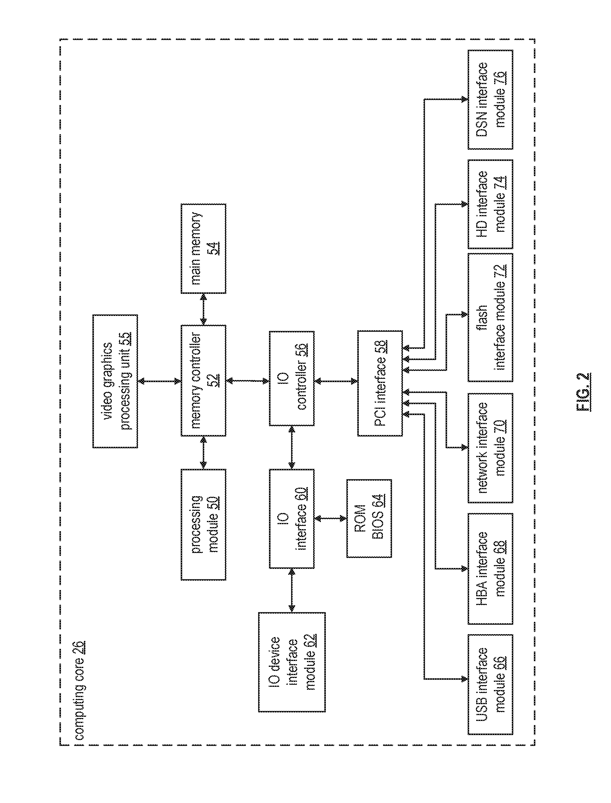
FIG. 2 is a schematic block diagram of an embodiment of a computing core in accordance with the invention;
FIG. 3 is a schematic block diagram of an example of dispersed storage error encoding of data in accordance with the present disclosure;
FIG. 4 is a schematic block diagram of a generic example of an error encoding function in accordance with the present disclosure;
FIG. 5 is a schematic block diagram of a specific example of an error encoding function in accordance with the present disclosure;
FIG. 6 is a schematic block diagram of an example of slice naming information for an encoded data slice (EDS) in accordance with the present disclosure;
FIG. 7 is a schematic block diagram of an example of dispersed storage error decoding of data in accordance with the present disclosure;
FIG. 8 is a schematic block diagram of a generic example of an error decoding function in accordance with the present disclosure;
FIG. 9 is a schematic block diagram of an example of a dispersed storage network in accordance with the present disclosure;
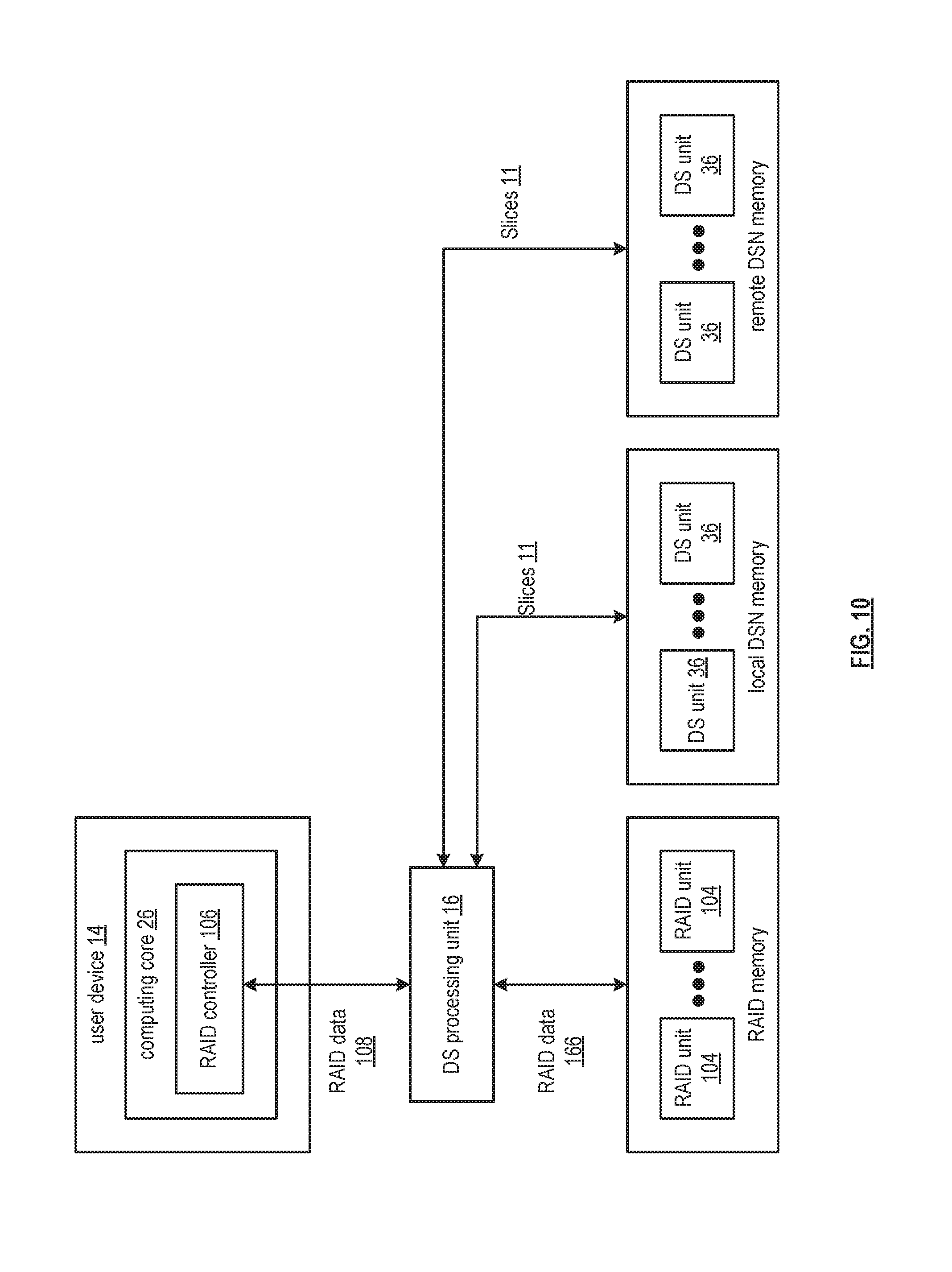
FIG. 10 is a schematic block diagram of another embodiment of a computing system in accordance with the invention;
FIG. 11 is a flowchart illustrating another example of storing data in accordance with the invention;
DETAILED DESCRIPTION OF THE INVENTION
FIG. 1 is a schematic block diagram of a computing system 10 that includes one or more of a first type of user devices 12, one or more of a second type of user devices 14, at least one distributed or dispersed storage (DS) processing unit 16, at least one DS managing unit 18, at least one storage integrity processing unit 20, and a distributed storage network (DSN) memory 22 coupled via a network 24. The network 24 may include one or more wireless and/or wire lined communication systems; one or more private intranet systems and/or public internet systems; and/or one or more local area networks (LAN) and/or wide area networks (WAN).
The DSN memory 22 includes a plurality of distributed storage (DS) units 36 for storing data of the system. Each of the DS units 36 includes a processing module and memory and may be located at a geographically different site than the other DS units (e.g., one in Chicago, one in Milwaukee, etc.). The processing module may be a single processing device or a plurality of processing devices. Such a processing device may be a microprocessor, micro-controller, digital signal processor, microcomputer, central processing unit, field programmable gate array, programmable logic device, state machine, logic circuitry, analog circuitry, digital circuitry, and/or any device that manipulates signals (analog and/or digital) based on hard coding of the circuitry and/or operational instructions. The processing module may have an associated memory and/or memory element, which may be a single memory device, a plurality of memory devices, and/or embedded circuitry of the processing module. Such a memory device may be a read-only memory, random access memory, volatile memory, non-volatile memory, static memory, dynamic memory, flash memory, cache memory, and/or any device that stores digital information. Note that if the processing module includes more than one processing device, the processing devices may be centrally located (e.g., directly coupled together via a wired and/or wireless bus structure) or may be distributedly located (e.g., cloud computing via indirect coupling via a local area network and/or a wide area network). Further note that when the processing module implements one or more of its functions via a state machine, analog circuitry, digital circuitry, and/or logic circuitry, the memory and/or memory element storing the corresponding operational instructions may be embedded within, or external to, the circuitry comprising the state machine, analog circuitry, digital circuitry, and/or logic circuitry. Still further note that, the memory element stores, and the processing module executes, hard coded and/or operational instructions corresponding to at least some of the steps and/or functions illustrated in FIGS. 1-11.
Each of the user devices 12-14, the DS processing unit 16, the DS managing unit 18, and the storage integrity processing unit 20 may be a portable computing device (e.g., a social networking device, a gaming device, a cell phone, a smart phone, a personal digital assistant, a digital music player, a digital video player, a laptop computer, a handheld computer, a video game controller, and/or any other portable device that includes a computing core) and/or a fixed computing device (e.g., a personal computer, a computer server, a cable set-top box, a satellite receiver, a television set, a printer, a fax machine, home entertainment equipment, a video game console, and/or any type of home or office computing equipment). Such a portable or fixed computing device includes a computing core 26 and one or more communications interfaces 30, 32, and/or 33. An embodiment of the computing core 26 will be described with reference to FIG. 2.
With respect to the interfaces, each of the interfaces 30, 32, and 33 includes software and/or hardware to support one or more communication links via the network 24 and/or directly. For example, interface 30 supports a communication link (wired, wireless, direct, via a LAN, via the network 24, etc.) between the first type of user device 14 and the DS processing unit 16. As another example, DSN interface 32 supports a plurality of communication links via the network 24 between the DSN memory 22 and the DS processing unit 16, the first type of user device 12, and/or the storage integrity processing unit 20. As yet another example, interface 33 supports a communication link between the DS managing unit 18 and any one of the other devices and/or units 12, 14, 16, 20, and/or 22 via the network 24.
In general, and with respect to data storage, the computing system 10 supports three primary functions: distributed network data storage management, distributed data storage and retrieval, and data storage integrity verification. In accordance with these three primary functions, data can be distributedly stored in a plurality of physically different locations and subsequently retrieved in a reliable and secure manner regardless of failures of individual storage devices, failures of network equipment, the duration of storage, the amount of data being stored, attempts at hacking the data, etc.
The DS managing unit 18 performs distributed network data storage management functions, which include establishing distributed data storage parameters, performing network operations, performing network administration, and/or performing network maintenance. The DS managing unit 18 establishes the distributed data storage parameters (e.g., allocation of virtual DSN memory space, distributed storage parameters, security parameters, billing information, user profile information, etc.) for one or more of the user devices 12-14 (e.g., established for individual devices, established for a user group of devices, established for public access by the user devices, etc.). For example, the DS managing unit 18 coordinates the creation of a vault (e.g., a virtual memory block) within the DSN memory 22 for a user device (for a group of devices, or for public access). The DS managing unit 18 also determines the distributed data storage parameters for the vault. In particular, the DS managing unit 18 determines a number of slices (e.g., the number that a data segment of a data file and/or data block is partitioned into for distributed storage) and a read threshold value (e.g., the minimum number of slices required to reconstruct the data segment).
As another example, the DS managing module 18 creates and stores, locally or within the DSN memory 22, user profile information. The user profile information includes one or more of authentication information, permissions, and/or the security parameters. The security parameters may include one or more of encryption/decryption scheme, one or more encryption keys, key generation scheme, and data encoding/decoding scheme.
As yet another example, the DS managing unit 18 creates billing information for a particular user, user group, vault access, public vault access, etc. For instance, the DS managing unit 18 tracks the number of times a user accesses a private vault and/or public vaults, which can be used to generate a per-access bill. In another instance, the DS managing unit 18 tracks the amount of data stored and/or retrieved by a user device and/or a user group, which can be used to generate a per-data-amount bill.
The DS managing unit 18 also performs network operations, network administration, and/or network maintenance. As at least part of performing the network operations and/or administration, the DS managing unit 18 monitors performance of the devices and/or units of the system 10 for potential failures, determines the devices' and/or units' activation status, determines the devices' and/or units' loading, and any other system level operation that affects the performance level of the computing system 10. For example, the DS managing unit 18 receives and aggregates network management alarms, alerts, errors, status information, performance information, and messages from the devices 12-14 and/or the units 16, 20, 22. For example, the DS managing unit 18 receives a simple network management protocol (SNMP) message regarding the status of the DS processing unit 16.
The DS managing unit 18 performs the network maintenance by identifying equipment within the computing system 10 that needs replacing, upgrading, repairing, and/or expanding. For example, the DS managing unit 18 determines that the DSN memory 22 needs more DS units 36 or that one or more of the DS units 36 needs updating.
The second primary function (i.e., distributed data storage and retrieval) begins and ends with a user device 12-14. For instance, if a second type of user device 14 has a data file 38 and/or data block 40 to store in the DSN memory 22, it sends the data file 38 and/or data block 40 to the DS processing unit 16 via its interface 30. As will be described in greater detail with reference to FIG. 2, the interface 30 functions to mimic a conventional operating system (OS) file system interface (e.g., network file system (NFS), flash file system (FFS), disk file system (DFS), file transfer protocol (FTP), web-based distributed authoring and versioning (WebDAV), etc.) and/or a block memory interface (e.g., small computer system interface (SCSI), internet small computer system interface (iSCSI), etc.). In addition, the interface 30 may attach a user identification code (ID) to the data file 38 and/or data block 40.
The DS processing unit 16 receives the data file 38 and/or data block 40 via its interface 30 and performs a distributed storage (DS) process 34 thereon (e.g., an error coding dispersal storage function). The DS processing 34 begins by partitioning the data file 38 and/or data block 40 into one or more data segments, which is represented as Y data segments. For example, the DS processing 34 may partition the data file 38 and/or data block 40 into a fixed byte size segment (e.g., 2.sup.1 to 2.sup.n bytes, where n=>2) or a variable byte size (e.g., change byte size from segment to segment, or from groups of segments to groups of segments, etc.).
For each of the Y data segments, the DS processing 34 error encodes (e.g., forward error correction (FEC), information dispersal algorithm, or error correction coding) and slices (or slices then error encodes) the data segment into a plurality of error coded (EC) data slices 42-48, which is represented as X slices per data segment. The number of slices (X) per segment, which corresponds to a number of pillars n, is set in accordance with the distributed data storage parameters and the error coding scheme. For example, if a Reed-Solomon (or other FEC scheme) is used in an n/k system, then a data segment is divided into n slices, where k number of slices is needed to reconstruct the original data (i.e., k is the threshold). As a few specific examples, the n/k factor may be 5/3; 6/4; 8/6; 8/5; 16/10.
For each EC slice 42-48, the DS processing unit 16 creates a unique slice name and appends it to the corresponding EC slice 42-48. The slice name includes universal DSN memory addressing routing information (e.g., virtual memory addresses in the DSN memory 22) and user-specific information (e.g., user ID, file name, data block identifier, etc.).
The DS processing unit 16 transmits the plurality of EC slices 42-48 to a plurality of DS units 36 of the DSN memory 22 via the DSN interface 32 and the network 24. The DSN interface 32 formats each of the slices for transmission via the network 24. For example, the DSN interface 32 may utilize an internet protocol (e.g., TCP/IP, etc.) to packetize the EC slices 42-48 for transmission via the network 24.
The number of DS units 36 receiving the EC slices 42-48 is dependent on the distributed data storage parameters established by the DS managing unit 18. For example, the DS managing unit 18 may indicate that each slice is to be stored in a different DS unit 36. As another example, the DS managing unit 18 may indicate that like slice numbers of different data segments are to be stored in the same DS unit 36. For example, the first slice of each of the data segments is to be stored in a first DS unit 36, the second slice of each of the data segments is to be stored in a second DS unit 36, etc. In this manner, the data is encoded and distributedly stored at physically diverse locations to improve data storage integrity and security. Further examples of encoding the data segments will be provided with reference to one or more of FIGS. 2-11.
Each DS unit 36 that receives an EC slice 42-48 for storage translates the virtual DSN memory address of the slice into a local physical address for storage. Accordingly, each DS unit 36 maintains a virtual to physical memory mapping to assist in the storage and retrieval of data.
The first type of user device 12 performs a similar function to store data in the DSN memory 22 with the exception that it includes the DS processing. As such, the device 12 encodes and slices the data file and/or data block it has to store. The device then transmits the slices 11 to the DSN memory via its DSN interface 32 and the network 24.
For a second type of user device 14 to retrieve a data file or data block from memory, it issues a read command via its interface 30 to the DS processing unit 16. The DS processing unit 16 performs the DS processing 34 to identify the DS units 36 storing the slices of the data file and/or data block based on the read command. The DS processing unit 16 may also communicate with the DS managing unit 18 to verify that the user device 14 is authorized to access the requested data.
Assuming that the user device is authorized to access the requested data, the DS processing unit 16 issues slice read commands to at least a threshold number of the DS units 36 storing the requested data (e.g., to at least 10 DS units for a 16/10 error coding scheme). Each of the DS units 36 receiving the slice read command, verifies the command, accesses its virtual to physical memory mapping, retrieves the requested slice, or slices, and transmits it to the DS processing unit 16.
Once the DS processing unit 16 has received a read threshold number of slices for a data segment, it performs an error decoding function and de-slicing to reconstruct the data segment. When Y number of data segments has been reconstructed, the DS processing unit 16 provides the data file 38 and/or data block 40 to the user device 14. Note that the first type of user device 12 performs a similar process to retrieve a data file and/or data block.
The storage integrity processing unit 20 performs the third primary function of data storage integrity verification. In general, the storage integrity processing unit 20 periodically retrieves slices 45, and/or slice names, of a data file or data block of a user device to verify that one or more slices have not been corrupted or lost (e.g., the DS unit failed). The retrieval process mimics the read process previously described.
If the storage integrity processing unit 20 determines that one or more slices is corrupted or lost, it rebuilds the corrupted or lost slice(s) in accordance with the error coding scheme. The storage integrity processing unit 20 stores the rebuild slice, or slices, in the appropriate DS unit(s) 36 in a manner that mimics the write process previously described.
FIG. 2 is a schematic block diagram of an embodiment of a computing core 26 that includes a processing module 50, a memory controller 52, main memory 54, a video graphics processing unit 55, an input/output (IO) controller 56, a peripheral component interconnect (PCI) interface 58, an IO interface 60, at least one IO device interface module 62, a read only memory (ROM) basic input output system (BIOS) 64, and one or more memory interface modules. The memory interface module(s) includes one or more of a universal serial bus (USB) interface module 66, a host bus adapter (HBA) interface module 68, a network interface module 70, a flash interface module 72, a hard drive interface module 74, and a DSN interface module 76. Note the DSN interface module 76 and/or the network interface module 70 may function as the interface 30 of the user device 14 of FIG. 1. Further note that the IO device interface module 62 and/or the memory interface modules may be collectively or individually referred to as IO ports.
The processing module 50 may be a single processing device or a plurality of processing devices. Such a processing device may be a microprocessor, micro-controller, digital signal processor, microcomputer, central processing unit, field programmable gate array, programmable logic device, state machine, logic circuitry, analog circuitry, digital circuitry, and/or any device that manipulates signals (analog and/or digital) based on hard coding of the circuitry and/or operational instructions. The processing module 50 may have an associated memory and/or memory element, which may be a single memory device, a plurality of memory devices, and/or embedded circuitry of the processing module 50. Such a memory device may be a read-only memory, random access memory, volatile memory, non-volatile memory, static memory, dynamic memory, flash memory, cache memory, and/or any device that stores digital information. Note that if the processing module 50 includes more than one processing device, the processing devices may be centrally located (e.g., directly coupled together via a wired and/or wireless bus structure) or may be distributedly located (e.g., cloud computing via indirect coupling via a local area network and/or a wide area network). Further note that when the processing module 50 implements one or more of its functions via a state machine, analog circuitry, digital circuitry, and/or logic circuitry, the memory and/or memory element storing the corresponding operational instructions may be embedded within, or external to, the circuitry comprising the state machine, analog circuitry, digital circuitry, and/or logic circuitry. Still further note that, the memory element stores, and the processing module 50 executes, hard coded and/or operational instructions corresponding to at least some of the steps and/or functions illustrated in the Figures referred to below.
FIG. 3 is a schematic block diagram of an example of dispersed storage error encoding of data. When a computing device 12 or 16 has data to store it disperse storage error encodes the data in accordance with a dispersed storage error encoding process based on dispersed storage error encoding parameters. The dispersed storage error encoding parameters include an encoding function (e.g., information dispersal algorithm, Reed-Solomon, Cauchy Reed-Solomon, systematic encoding, non-systematic encoding, on-line codes, etc.), a data segmenting protocol (e.g., data segment size, fixed, variable, etc.), and per data segment encoding values. The per data segment encoding values include a total, or pillar width, number (T) of encoded data slices per encoding of a data segment (i.e., in a set of encoded data slices); a decode threshold number (D) of encoded data slices of a set of encoded data slices that are needed to recover the data segment; a read threshold number (R) of encoded data slices to indicate a number of encoded data slices per set to be read from storage for decoding of the data segment; and/or a write threshold number (W) to indicate a number of encoded data slices per set that must be accurately stored before the encoded data segment is deemed to have been properly stored. The dispersed storage error encoding parameters may further include slicing information (e.g., the number of encoded data slices that will be created for each data segment) and/or slice security information (e.g., per encoded data slice encryption, compression, integrity checksum, etc.).
In the present example, Cauchy Reed-Solomon has been selected as the encoding function (a generic example is shown in FIG. 4 and a specific example is shown in FIG. 5); the data segmenting protocol is to divide the data object into fixed sized data segments; and the per data segment encoding values include: a pillar width of 5, a decode threshold of 3, a read threshold of 4, and a write threshold of 4. In accordance with the data segmenting protocol, the computing device 12 or 16 divides the data (e.g., a file (e.g., text, video, audio, etc.), a data object, or other data arrangement) into a plurality of fixed sized data segments (e.g., 1 through Y of a fixed size in range of Kilo-bytes to Tera-bytes or more). The number of data segments created is dependent of the size of the data and the data segmenting protocol.
The computing device 12 or 16 then disperse storage error encodes a data segment using the selected encoding function (e.g., Cauchy Reed-Solomon) to produce a set of encoded data slices. FIG. 4 illustrates a generic Cauchy Reed-Solomon encoding function, which includes an encoding matrix (EM), a data matrix (DM), and a coded matrix (CM). The size of the encoding matrix (EM) is dependent on the pillar width number (T) and the decode threshold number (D) of selected per data segment encoding values. To produce the data matrix (DM), the data segment is divided into a plurality of data blocks and the data blocks are arranged into D number of rows with Z data blocks per row. Note that Z is a function of the number of data blocks created from the data segment and the decode threshold number (D). The coded matrix is produced by matrix multiplying the data matrix by the encoding matrix.
FIG. 5 illustrates a specific example of Cauchy Reed-Solomon encoding with a pillar number (T) of five and decode threshold number of three. In this example, a first data segment is divided into twelve data blocks (D1-D12). The coded matrix includes five rows of coded data blocks, where the first row of X11-X14 corresponds to a first encoded data slice (EDS 1_1), the second row of X21-X24 corresponds to a second encoded data slice (EDS 2_1), the third row of X31-X34 corresponds to a third encoded data slice (EDS 3_1), the fourth row of X41-X44 corresponds to a fourth encoded data slice (EDS 4_1), and the fifth row of X51-X54 corresponds to a fifth encoded data slice (EDS 5_1). Note that the second number of the EDS designation corresponds to the data segment number. In the illustrated example, the value X11=aD1+bD5+cD9, X12=aD2+bD6+cD10, . . . X53=mD3+nD7+oD11, and X54=mD4+nD8+oD12.
Returning to the discussion of FIG. 3, the computing device also creates a slice name (SN) for each encoded data slice (EDS) in the set of encoded data slices. A typical format for a slice name 80 is shown in FIG. 6. As shown, the slice name (SN) 80 includes a pillar number of the encoded data slice (e.g., one of 1-T), a data segment number (e.g., one of 1-Y), a vault identifier (ID), a data object identifier (ID), and may further include revision level information of the encoded data slices. The slice name functions as at least part of a DSN address for the encoded data slice for storage and retrieval from the DSN memory 22.
As a result of encoding, the computing device 12 or 16 produces a plurality of sets of encoded data slices, which are provided with their respective slice names to the storage units for storage. As shown, the first set of encoded data slices includes EDS 1_1 through EDS 5_1 and the first set of slice names includes SN 1_1 through SN 5_1 and the last set of encoded data slices includes EDS 1_Y through EDS 5_Y and the last set of slice names includes SN 1_Y through SN 5_Y.
FIG. 7 is a schematic block diagram of an example of dispersed storage error decoding of a data object that was dispersed storage error encoded and stored in the example of FIG. 4. In this example, the computing device 12 or 16 retrieves from the storage units at least the decode threshold number of encoded data slices per data segment. As a specific example, the computing device retrieves a read threshold number of encoded data slices.
In order to recover a data segment from a decode threshold number of encoded data slices, the computing device uses a decoding function as shown in FIG. 8. As shown, the decoding function is essentially an inverse of the encoding function of FIG. 4. The coded matrix includes a decode threshold number of rows (e.g., three in this example) and the decoding matrix in an inversion of the encoding matrix that includes the corresponding rows of the coded matrix. For example, if the coded matrix includes rows 1, 2, and 4, the encoding matrix is reduced to rows 1, 2, and 4, and then inverted to produce the decoding matrix.
FIG. 9 is a diagram of an example of a dispersed storage network. The dispersed storage network includes a DS (dispersed storage) client module 34 (which may be in DS computing devices 12 and/or 16 of FIG. 1), a network 24, and a plurality of DS units 36-1 . . . 36-n (which may be storage units 36 of FIG. 1 and which form at least a portion of DS memory 22 of FIG. 1), a DSN managing unit (not shown--device 18 in FIG. 1), and a DS integrity verification module 20. The DS client module 34 includes an outbound DS processing section 81 and an inbound DS processing section 82. Each of the DS units 36-1 . . . 36-n includes a controller 86, a processing module 84 including a communications interface for communicating over network 24 (not shown), memory 88, a DT (distributed task) execution module 90, and a DS client module 34.
In an example of operation, the DS client module 34 receives data 92. The data 92 may be of any size and of any content, where, due to the size (e.g., greater than a few Terabytes), the content (e.g., secure data, etc.), and/or concerns over security and loss of data, distributed storage of the data is desired. For example, the data 92 may be one or more digital books, a copy of a company's emails, a large-scale Internet search, a video security file, one or more entertainment video files (e.g., television programs, movies, etc.), data files, and/or any other large amount of data (e.g., greater than a few Terabytes).
Within the DS client module 34, the outbound DS processing section 81 receives the data 92. The outbound DS processing section 81 processes the data 92 to produce slice groupings 96. As an example of such processing, the outbound DS processing section 81 partitions the data 92 into a plurality of data partitions. For each data partition, the outbound DS processing section 81 dispersed storage (DS) error encodes the data partition to produce encoded data slices and groups the encoded data slices into a slice grouping 96.
The outbound DS processing section 81 then sends, via the network 24, the slice groupings 96 to the DS units 36-1 . . . 36-n of the DSN memory 22 of FIG. 1. For example, the outbound DS processing section 81 sends slice group to DS storage unit 36-1. As another example, the outbound DS processing section 81 sends slice group #n to DS unit #n.
In one example of operation, the DS client module 34 requests retrieval of stored data within the memory of the DS units 36. In this example, the task 94 is retrieve data stored in the DSN memory 22. Accordingly, and according to one embodiment, the outbound DS processing section 81 converts the task 94 into a plurality of partial tasks 98 and sends the partial tasks 98 to the respective DS storage units 36-1 . . . 36-n.
In response to the partial task 98 of retrieving stored data, a DS storage unit 36 identifies the corresponding encoded data slices 99 and retrieves them. For example, DS unit #1 receives partial task #1 and retrieves, in response thereto, retrieved slices #1. The DS units 36 send their respective retrieved slices 99 to the inbound DS processing section 82 via the network 24.
The inbound DS processing section 82 converts the retrieved slices 99 into data 92. For example, the inbound DS processing section 82 de-groups the retrieved slices 99 to produce encoded slices per data partition. The inbound DS processing section 82 then DS error decodes the encoded slices per data partition to produce data partitions. The inbound DS processing section 82 de-partitions the data partitions to recapture the data 92.
The DSN and related processes described above in connection with FIGS. 1-9 can be used in conjunction with a redundant array of independent disks system as will be further explained with reference to FIGS. 10 and 11. FIG. 10 is a schematic block diagram of another embodiment of a computing system that includes at least one user device 14, at least one redundant array of independent disks (RAID) memory 102, at least one dispersed storage (DS) processing unit 16, at least one local dispersed storage network (DSN) memory 22, and at least one remote DSN memory 23. Note that the local DSN memory 22 and the remote DSN memory 23 include a plurality of dispersed storage (DS) units 36, wherein the DS units 36 of the local DSN memory 22 are deployed at one or more sites within local proximity (e.g., at a same site) to the DS processing unit 16 and/or the user device 14, and wherein the DS units 36 of the remote DSN memory 23 are deployed at one or more sites not within local proximity (e.g., not at the same site) to the DS processing unit 16 and/or the user device 14. User device 14 includes a computing core 26, wherein the computing core 26 includes a RAID controller 106. Alternatively, or in addition to, the user device 14 may include a DS processing as discussed previously. The RAID memory 102 includes a plurality of RAID units 104. The RAID controller 106 stores RAID data 108 in the RAID memory 102 as RAID data 166 via the DS processing unit 16 and/or RAID data 108 in the local DSN memory 22 and/or remote DSN memory 23 via the DS processing unit 16 as encoded data slices 11. RAID memory 102 includes two or more RAID units 104 (e.g. disk drives) where data and data stripes are stored with at least one RAID method.
The DS processing unit 16 facilitates at least three primary functions of the system. In a first primary function, the DS processing unit 16 facilitates storing RAID data 108 as encoded data slices 11 in the local DSN memory 22 and/or remote DSN memory 23 (e.g., in response to a RAID data storage request from the RAID controller 106) and/or as RAID data 166 in the RAID memory 102. In a second primary function, the DS processing unit 16 facilitates retrieving the encoded data slices 11 from the local DSN memory 22 and/or the remote DSN memory 23 and dispersed storage error decoding encoded slices to produce recovered RAID data, and/or retrieving RAID data 166 from the RAID memory 102 to produce retrieved RAID data. Next, the processing module sends the recovered RAID data and/or the retrieved RAID data as the RAID data 108 to the RAID controller 106 (e.g., in response to a RAID data retrieval request from the RAID controller 106). In a third primary function, the DS processing unit 16 facilitates migrating data between any of the RAID memory 102, the local DSN memory 22, and the remote DSN memory 23.
In an example of a data storing operation, the DS processing unit 16 receives RAID data 108 from the RAID controller 106, wherein the RAID data 108 includes a store RAID data command. The DS processing unit 16 determines which memories to utilize based on matching storage requirements to the storage capabilities of the RAID memory 102, the local DSN memory 22, and the remote DSN memory 23 and produces a determination. E.g. DS processing unit 16 can determine whether to process RAID data using RAID memory 102, DSN memory (including local DSN 22 and/or remote DSN 23) or both the RAID memory and one or more DSN memories. The DS processing unit 16 can then process the RAID data 108 based on the determination. The DS processing unit 16 saves the selected memory location as a memory indicator for subsequent use in a retrieval scenario. Next, the DS processing unit 16 determines a DS method when storing a portion of the RAID data 108 as encoded data slices. The DS processing unit 16 creates encoded data slices of the RAID data in accordance with the DS method when storing a portion of the RAID data 108 as encoded data slices. The DS processing unit 16 determines which of the local DSN memory 22 and the remote DSN memory 23 to utilize when storing encoded data slices in a DSN memory. The DS processing unit 16 sends the encoded data slices with a store command to the local DSN memory 22 and/or the remote DSN memory 23 for storage therein. The DS processing unit 16 stores at least a portion of the RAID data 108 as RAID data 166 in the RAID memory 102 when storing another portion of the RAID data 108 as RAID data. The method to store RAID data is discussed in greater detail with reference to FIG. 11.
In an example of data retrieval operation, the DS processing unit 16 receives RAID data 108 from the RAID controller 106, wherein the RAID data 108 includes a retrieve RAID data request. The DS processing unit 16 determines the memory locations of data associated with the retrieve RAID data request. For example, the processing module determines the encoded data slices 11 stored in the local DSN memory 22 corresponding to a portion of the requested RAID data based on where the desired data stored as indicated by the memory indicator. The DS processing unit 16 retrieves the encoded data slices from the local DSN memory 22 when the local DSN memory 22 stores at least a portion of the requested data. Next, the DS processing unit 16 determines the DS method and recovers RAID data from the retrieved encoded data slices in accordance with the DS method to produce recovered RAID data. The DS processing unit 16 retrieves a portion of the RAID data as retrieved RAID data 166 from the RAID memory 102 when the processing module determines that a portion of requested data is stored in the RAID memory 102. Next, the DS processing unit 16 aggregates the recovered RAID data from the local DSN memory 22 and the retrieved RAID data from the RAID memory 102 to produce RAID data. The DS processing unit 16 sends the RAID data as RAID data 108 to the RAID controller 106 in response to the RAID data retrieval request.
In an example of a data migration operation, the DS processing unit 16 sends RAID data 166 (e.g., including a retrieve RAID data request) to the RAID memory 102 to retrieve stored RAID data from the RAID memory 102 when the DS processing unit 16 determines to migrate RAID data from the RAID memory 102 to the local DSN memory 22 and/or the remote DSN memory 23 as encoded data slices. Next, the DS processing unit 16 receives RAID data 166 from the RAID memory 102. The DS processing unit 16 dispersed storage error encodes data of the RAID data 166 to produce encoded data slices. The DS processing unit 16 determines which of the local DSN memory 22 in the remote DSN memory 23 to utilize to store the encoded data slices. Next, the DS processing unit 16 sends the encoded data slices to the local DSN memory 22 and/or the remote DSN memory 23 for storage therein. As another example of data migration, the DS processing unit 16 retrieves encoded data slices from the remote DSN memory 23, dispersed storage error decodes the encoded data slices to produce data, transforms the data into RAID data, and sends the RAID data 166 to the RAID memory 102 for storage therein. As yet another example of data migration, the DS processing unit 16 retrieves encoded data slices from the local DSN memory 22 and sends the encoded data slices to the remote DSN memory 23 for storage therein.
Alternatively, or in addition to, the DS processing unit 16 may determine to delete one or more copies of RAID data from one or more of the RAID memory 102, the local DSN memory 22, and/or the remote DSN memory 23. Such a determination may be based on one or more of an access frequency, performance requirements, metadata, costs, and other factors to optimize the use of all of the memory types.
According to another example, the DS processing unit 16 forwards all traffic to and from RAID controller 106 and RAID memory 102 and may backup or store selected data in local DSN memory 22 and/or remote DSN memory 23. The selected data could be all or a subset of RAID data 108 and could be selected based on retrieval frequency. The backup of selected data, or more generally the determination, could occur in response to an attempt to store data to RAID memory 102 and/or as a background task sifting through RAID memory 102. As part of a retrieval process, a DS processing unit 16 can retrieve slices 11 (including RAID data) from local DSN memory 22 and/or remote DSN memory 23 when RAID memory fails, and may rebuild the RAID data 108 using the slices 22 retrieved from DSN memory.
According to another example, the DS processing unit 16 interfaces to RAID controller 106 to look like a RAID array. DS processing unit 1 stores slices to, and/or retrieves and/or deletes slices from, local DSN memory 22 and/or remote DSN memory 23, and/or RAID memory based on data stripes and/or metadata requirements. This can involve determining which DSN memories to use based on requirements and resources. One example DS processing method involves keeping track of the retrieval frequency of data and, based in part on the retrieval frequency, redistributing the storage location of the data from time to time.
According to another example, the DS processing unit 16 interfaces to RAID memory 102 to selectively backup the RAID array based on one or more of: meta data (e.g. a flag, data type, user ID, priority, security), a timer or timing (e.g., every day, every hour, every week . . . ), and data use activity (e.g. conduct backup more frequency for active data). This can involve determining which DSN memories to used being based on requirements and resources.
In one example, the local DSN memory 22 is co-located with RAID memory 102 for fast access and includes at least a read and write threshold number of DS units 36. In another example, remote DSN memory 23 has DS units 36 at at least one other site for improved reliability and may be used for a first or second backup copy of data. DS processing unit 16 may delete RAID memory 102 copy and/or local DSN memory 22 when fast access is no longer required (local DSN memory may be enough) based on use pattern, performance requirements, metadata, cost, etc.
FIG. 11 is a flowchart illustrating another example of storing data. The method begins with step 114 where a processing module receives redundant array of independent disks (RAID) data to store and then continues with step 138 to determine metadata. The method continues at step 246 where the processing module determines which memories (e.g., a RAID memory, local and/or remote dispersed storage network (DSN) memory) to utilize based on one or more of the metadata, the RAID data, a vault lookup, a command, a message, a performance indicator, a predetermination, local DSN memory capabilities, remote DSN memory capabilities, RAID memory capabilities, and a comparison of requirements to capabilities of the RAID memory and local and/or DSN memory. The processing module saves the determination choice in a memory indicator that is stored in one or more of the RAID memory, the local DSN memory, the remote DSN memory, and a DSN user vault. The RAID data to store may include: a data object name; a data object size; a data type; a data block; parity information; and drive information. Data blocks may be organized into stripes per drive. Metadata can include: a user ID, a data type, a data object name, an expected access frequency, a requirement for priority, a requirement for security, a requirement for performance and a requirement for when to backup based on access frequency. Step 138 (determine metadata) can be based on a vault lookup, a command message, a predetermination, a data object name, a data object size, a data type, a data block, parity information, drive information and stripes.
For example, the processing module determines to utilize the remote DSN memory when the performance indicator indicates that reliability is favored over low access latency and the remote DSN memory has a high reliability capability. As another example, the processing module determines to utilize the local RAID memory when the performance indicator indicates that low access latency is favored over reliability and the local RAID memory has a low access latency capability. As yet another example, the processing module determines to utilize both the local DSN memory and the RAID memory when the performance indicator indicates that both low access latency and good reliability is required and that the RAID memory has the capability of low access latency and the local DSN memory has the capability of good reliability. The method branches to the step 250 when the processing module determines to not utilize the RAID memory. The method continues to step 172 when the processing module determines to utilize the RAID memory. The method continues at step 172 where the processing module forwards the RAID data to the RAID memory. In another example, RAID memory is used for fast performance, local DSN memory for fast access requirements and remote DSN for higher reliability requirements.
The method continues at step 250 where the processing module determines whether to utilize the local DSN memory based on the previous memory determination. The method branches to step 256 when the processing module determines to not utilize the local DSN memory. The method continues to step 116 when the processing module determines to utilize the local DSN memory. The method continues with step 116 of to determine a DS method. The method continues at step 252 where the processing module determines local error coding dispersal storage function parameters (e.g., operational parameters). Such a determination may be based on one or more of a vault lookup, RAID memory configuration information, a performance indicator, a command, a message, a predetermination, a data object name, a data object, a data object size, a data type, a data block, parity information, a user ID, RAID unit information, disk drive information, address information, memory information, a command, and a request. For example, the processing module determines the local error coding dispersal storage function parameters to include a pillar width of 4 and a decode threshold of 3 to provide fast performance and moderate reliability in accordance with a local proximity of an associated local DSN memory. The method continues with step 120 to produce encoded data slices from the RAID data. The method continues at step 254 where the processing module sends the encoded data slices to the local DSN memory for storage therein.
The method continues at step 256 where the processing module determines whether to utilize the remote DSN memory based on the previous memory determination. The method ends at step 262 when the processing module determines not to utilize the remote DSN memory. The method continues to step 116 when the processing module determines to utilize the remote DSN memory. The method continues with step 116 to determine the DS method. The method continues at step 258 where the processing module determines remote error coding dispersal storage function parameters (e.g., operational parameters), which may be the same as or different from local operational parameters. Such a determination may be based on one or more of a vault lookup, local error coding dispersal storage function parameters, RAID memory configuration information, a performance indicator, a command, a message, a predetermination, a data object name, a data object, a data object size, a data type, a data block, parity information, a user ID, RAID unit information, disk drive information, address information, memory information, a command, and a request. For example, the processing module determines the remote error coding dispersal storage function parameters to include a pillar width of 32 and a decode threshold of 20 to provide high reliability in accordance with a remote proximity of an associated remote DSN memory. The method continues with step 120 to produce encoded data slices from the RAID data. The method continues at step 260 where the processing module sends the encoded data slices to one or more remote DSN memories for storage therein.
The methods and processes set out above could be embodied in a computer readable memory device having a storage section that stores operational instructions that, when executed by a computing device, causes the computing device to perform certain functions.
As may be used herein, the terms "substantially" and "approximately" provides an industry-accepted tolerance for its corresponding term and/or relativity between items. Such an industry-accepted tolerance ranges from less than one percent to fifty percent and corresponds to, but is not limited to, component values, integrated circuit process variations, temperature variations, rise and fall times, and/or thermal noise. Such relativity between items ranges from a difference of a few percent to magnitude differences. As may also be used herein, the term(s) "operably coupled to", "coupled to", and/or "coupling" includes direct coupling between items and/or indirect coupling between items via an intervening item (e.g., an item includes, but is not limited to, a component, an element, a circuit, and/or a module) where, for indirect coupling, the intervening item does not modify the information of a signal but may adjust its current level, voltage level, and/or power level. As may further be used herein, inferred coupling (i.e., where one element is coupled to another element by inference) includes direct and indirect coupling between two items in the same manner as "coupled to". As may even further be used herein, the term "operable to" or "operably coupled to" indicates that an item includes one or more of power connections, input(s), output(s), etc., to perform, when activated, one or more its corresponding functions and may further include inferred coupling to one or more other items. As may still further be used herein, the term "associated with", includes direct and/or indirect coupling of separate items and/or one item being embedded within another item. As may be used herein, the term "compares favorably", indicates that a comparison between two or more items, signals, etc., provides a desired relationship. For example, when the desired relationship is that signal 1 has a greater magnitude than signal 2, a favorable comparison may be achieved when the magnitude of signal 1 is greater than that of signal 2 or when the magnitude of signal 2 is less than that of signal 1.
The present invention has also been described above with the aid of method steps illustrating the performance of specified functions and relationships thereof. The boundaries and sequence of these functional building blocks and method steps have been arbitrarily defined herein for convenience of description. Alternate boundaries and sequences can be defined so long as the specified functions and relationships are appropriately performed. Any such alternate boundaries or sequences are thus within the scope and spirit of the claimed invention.
The present invention has been described, at least in part, in terms of one or more embodiments. An embodiment of the present invention is used herein to illustrate the present invention, an aspect thereof, a feature thereof, a concept thereof, and/or an example thereof. A physical embodiment of an apparatus, an article of manufacture, a machine, and/or of a process that embodies the present invention may include one or more of the aspects, features, concepts, examples, etc. described with reference to one or more of the embodiments discussed herein.
The present invention has been described above with the aid of functional building blocks illustrating the performance of certain significant functions. The boundaries of these functional building blocks have been arbitrarily defined for convenience of description. Alternate boundaries could be defined as long as the certain significant functions are appropriately performed. Similarly, flow diagram blocks may also have been arbitrarily defined herein to illustrate certain significant functionality. To the extent used, the flow diagram block boundaries and sequence could have been defined otherwise and still perform the certain significant functionality. Such alternate definitions of both functional building blocks and flow diagram blocks and sequences are thus within the scope and spirit of the claimed invention. One of average skill in the art will also recognize that the functional building blocks, and other illustrative blocks, modules and components herein, can be implemented as illustrated or by discrete components, application specific integrated circuits, processors executing appropriate software and the like or any combination thereof.
* * * * *
D00000
D00001
D00002
D00003
D00004
D00005
D00006
D00007
XML
uspto.report is an independent third-party trademark research tool that is not affiliated, endorsed, or sponsored by the United States Patent and Trademark Office (USPTO) or any other governmental organization. The information provided by uspto.report is based on publicly available data at the time of writing and is intended for informational purposes only.
While we strive to provide accurate and up-to-date information, we do not guarantee the accuracy, completeness, reliability, or suitability of the information displayed on this site. The use of this site is at your own risk. Any reliance you place on such information is therefore strictly at your own risk.
All official trademark data, including owner information, should be verified by visiting the official USPTO website at www.uspto.gov. This site is not intended to replace professional legal advice and should not be used as a substitute for consulting with a legal professional who is knowledgeable about trademark law.