Technique for preventing air lock through stuttered starting and air release slit for pumps
Lopes , et al.
U.S. patent number 10,267,317 [Application Number 13/917,970] was granted by the patent office on 2019-04-23 for technique for preventing air lock through stuttered starting and air release slit for pumps. This patent grant is currently assigned to Flow Control LLC.. The grantee listed for this patent is Flow Control LLC. Invention is credited to Jesus Estrada, Jeffrey Lopes, Kevin Teed.


| United States Patent | 10,267,317 |
| Lopes , et al. | April 23, 2019 |
Technique for preventing air lock through stuttered starting and air release slit for pumps
Abstract
Apparatus, including a pumping system, is provided featuring a pump and a control circuit. The pump has an impeller housing configured with a slit at the top for trapped air to leave the impeller housing once the pump has been submerged. The control circuit is configured to cycle the pump on and off for a predetermined number of cycles so that the trapped air will float to the top and be expelled out the slit when the pump is cycled off. The control circuit is configured to leave the pump on after the predetermined number of cycles.
| Inventors: | Lopes; Jeffrey (Gloucester, MA), Estrada; Jesus (Gloucester, MA), Teed; Kevin (Lawrence, MA) | ||||||||||
|---|---|---|---|---|---|---|---|---|---|---|---|
| Applicant: |
|
||||||||||
| Assignee: | Flow Control LLC. (Beverly,
MA) |
||||||||||
| Family ID: | 49756060 | ||||||||||
| Appl. No.: | 13/917,970 | ||||||||||
| Filed: | June 14, 2013 |
Prior Publication Data
| Document Identifier | Publication Date | |
|---|---|---|
| US 20130336763 A1 | Dec 19, 2013 | |
Related U.S. Patent Documents
| Application Number | Filing Date | Patent Number | Issue Date | ||
|---|---|---|---|---|---|
| 61659631 | Jun 14, 2012 | ||||
| Current U.S. Class: | 1/1 |
| Current CPC Class: | F04D 9/003 (20130101); F04D 13/086 (20130101); F04D 9/006 (20130101); F04D 15/0066 (20130101); F04D 15/0094 (20130101); F05D 2260/85 (20130101) |
| Current International Class: | F04D 15/00 (20060101); F04D 9/00 (20060101); F04D 13/08 (20060101) |
| Field of Search: | ;417/423.3,435,12,211.5,306,366 |
References Cited [Referenced By]
U.S. Patent Documents
| 2643615 | June 1953 | Murphy |
| 2910003 | October 1959 | Kaatz |
| 3021788 | February 1962 | Kaatz |
| 3227089 | January 1966 | Haarhuis |
| 3291058 | December 1966 | McFarlin |
| 3325657 | June 1967 | Corey |
| 3406295 | October 1968 | Corey |
| 3575521 | April 1971 | Porter |
| 3867071 | February 1975 | Hartley |
| 4087204 | May 1978 | Niedermeyer |
| 4087994 | May 1978 | Goodlaxson |
| 4592700 | June 1986 | Toguchi |
| 4787816 | November 1988 | Jensen |
| 4913620 | April 1990 | Kusiak et al. |
| 4981413 | January 1991 | Elonen et al. |
| 5209641 | May 1993 | Hoglund |
| 5324170 | June 1994 | Anastos et al. |
| 5400732 | March 1995 | Berge |
| 5545012 | August 1996 | Anastos |
| 5577890 | November 1996 | Nielsen |
| 5599171 | February 1997 | Horwitz |
| 5632220 | May 1997 | Vento |
| 5647329 | July 1997 | Bucci et al. |
| 5769603 | June 1998 | Fujiwara |
| 5856783 | January 1999 | Gibb |
| 6203282 | March 2001 | Morin |
| 6206632 | March 2001 | Gallus |
| 6254353 | July 2001 | Polo |
| 6350105 | February 2002 | Kobayashi et al. |
| 6390780 | May 2002 | Batchelder et al. |
| 6457940 | October 2002 | Lehman |
| 6481973 | November 2002 | Struthers |
| 6676382 | January 2004 | Leighton |
| 6684946 | February 2004 | Gay |
| 7131330 | November 2006 | Gurega |
| 7232288 | June 2007 | Tibban |
| 7798215 | September 2010 | Leuthen |
| 8133034 | March 2012 | Mehlhorn et al. |
| 8602743 | December 2013 | Stiles, Jr. |
| 8760302 | June 2014 | MacDonald |
| 9404500 | August 2016 | Stiles, Jr. |
| 2003/0065425 | April 2003 | Goodwin et al. |
| 2005/0226731 | October 2005 | Mehlhorn |
| 2008/0226467 | September 2008 | Vento |
| 2008/0288115 | November 2008 | Rusnak |
| 2009/0038696 | February 2009 | Levin |
| 2010/0028166 | February 2010 | Collins et al. |
| 2010/0068073 | March 2010 | Branecky |
| 2010/0080714 | April 2010 | Mehlhorn |
| 2010/0319116 | December 2010 | Schmidt et al. |
| 2011/0002792 | January 2011 | Bartos |
| 2012/0125624 | May 2012 | Dyer |
| 2013/0336763 | December 2013 | Lopes |
| 1076885 | May 1980 | CA | |||
| 2911253 | Jun 2007 | CN | |||
| 200943584 | Sep 2007 | CN | |||
| 200964943 | Oct 2007 | CN | |||
| 29522235 | Jan 2001 | DE | |||
| 2320087 | May 2011 | EP | |||
| 2320087 | May 2011 | EP | |||
| 61164097 | Jul 1986 | JP | |||
| 03160195 | Jul 1991 | JP | |||
| 60741483 | Mar 1994 | JP | |||
Other References
|
Homer, "Report on new Pumping a systems software on Pumping Instrumentation and Control Skids", Apr. 19, 2001, Technical report. cited by examiner . 200943584CN English Language Abstract 1 page. cited by applicant . 60741483JP English Language Abstract 1 page. cited by applicant . 03160195JP English Language Abstract 1 page. cited by applicant . CN2911253 English Language Abstract (1 page). cited by applicant . CN200964943 English Language Abstract (1 page). cited by applicant . English language abstract and translation of JPS61164097A. cited by applicant. |
Primary Examiner: Hamo; Patrick
Assistant Examiner: Herrmann; Joseph S.
Attorney, Agent or Firm: Ware, Fressola, Maguire & Barber LLP
Parent Case Text
CROSS-REFERENCE TO RELATED APPLICATION
This application claims benefit to provisional patent application Ser. No. 61/659,631, filed 14 Jun. 2012, which is hereby incorporated by reference in its entirety.
Claims
We claim:
1. A stutter start anti-air lock system comprising: a pump having an impeller housing configured with a slit at the top for trapped air to leave the pump once the pump has been submerged in a liquid and the impeller housing contains an air/liquid mixture; and a control circuit configured to initiate a start-up process upon powering the pump to provide signaling to implement an anti air-lock on/off start-up cycle to cycle the pump on and off for a predetermined number of cycles, wherein trapped air not previously expelled once the pump has been submerged will float to the top and be expelled out the slit when the pump is cycled off, the control circuit also configured, once the start-up process is complete, to leave the pump on after the predetermined number of cycles until the pump is powered off, wherein the pump is configured with a motor coupled to an impeller via a shaft; and wherein a discharge from the impeller housing is a tangential discharge, the tangential discharge extending away from the impeller housing below a central axis of the shaft.
2. The stutter start anti-air lock system according to claim 1, wherein the stutter start anti-air lock system comprises a relay arranged between the pump and the control circuit, the relay configured to respond to the signaling provided from the control circuit and provide relay signaling to cycle the pump on and off for the predetermined number of cycles.
3. The stutter start anti-air lock system according to claim 1, wherein the stutter start anti-air lock system is configured as a pumping system having a combination of the pump and the control circuit.
4. The stutter start anti-air lock system according to claim 1, wherein the pump is configured to contain the control circuit, so as to have the control circuit arranged therein.
5. The stutter start anti-air lock system according to claim 1, wherein the pump is configured as a centrifugal pump.
6. The stutter start anti-air lock system according to claim 1, wherein the slit is configured at the highest point of the impeller housing; and the control circuit is configured for implementing the anti air-lock on/off start-up cycle to cycle the pump on for some time and off for some corresponding time for the predetermined number of cycles, and also configured to turn on the pump after implementation of the anti air-lock on/off start-up cycle.
7. The stutter start anti-air lock system according to claim 1, wherein the control circuit is configured at start-up to repeatedly turn the pump: on to fill the impeller housing with liquid after some trapped air in the air/liquid mixture is expelled out of the slit, and off to allow further trapped air in the air/liquid mixture to float to the top of the impeller housing and be expelled out of the slit for each one of the predetermined number of cycles.
8. The stutter start anti-air lock system according to claim 1, wherein each one of the predetermined number of cycles to cycle the pump on and off comprises powering the motor on and powering the motor off.
9. The stutter start anti-air lock system according to claim 8, wherein the control circuit is configured to provide signaling to turn the motor on and off in order to cycle the pump on and off.
10. The stutter start anti-air lock system according to claim 1, wherein the pump further comprises an outlet hose configured to allow the flow of water out of the pump when a pressure from the impeller overcomes a back pressure from the outlet hose.
11. The stutter start anti-air lock system according to claim 1, wherein upon each time the pump is started, the control circuit is configured to cycle the pump on and off for the predetermined number of cycles and to leave the pump on after the predetermined number of cycles until the pump is manually powered off.
12. The stutter start anti-air lock system according to claim 1, wherein the control circuit is arranged outside the pump.
13. The stutter start anti-air lock system according to claim 1, wherein cycling the pump off during the anti air-lock on/off start-up cycle causes the liquid in the air/liquid mixture in the impeller housing to calm and allows the air of the air/liquid mixture in the impeller housing to seep out the slit.
14. The stutter start anti-air lock system according to claim 1, wherein the slit is arranged on an outer wall of the pump and is configured to expel trapped air from the impeller housing to the liquid in which the pump is submerged.
Description
BACKGROUND OF THE INVENTION
1. Field of the Invention
This invention relates to a pump; and more particularly, relates to a centrifugal pump.
2. Description of Related Art
It is known in the art that if, e.g., a centrifugal pump, is turned on prior to being submerged air can become trapped inside of the housings containing the impellers causing them to pump a gas/liquid mixture instead of the pure liquid mixture they were designed to pump. When this occurs the pump tends to fail to pump water and the air must be expelled or pushed out of the system before the pump can operate as intended. When the pump fails, this situation is known as air lock.
FIG. 1 shows an air locked pump that is known in the art having a motor and an impeller for pumping an air/water mixture. With air inside the impeller housing, the impellers cannot create enough pressure to overcome the back pressure from the outlet hose. As shown, the pressure from the impellers is overcome by the back pressure from the outlet hose, so there is no flow out the outlet hose.
There are known devices whose purpose and intention is to prevent such air lock in, e.g., centrifugal pumps.
By way of example, U.S. Pat. No. 5,545,012, entitled, "Soft Star Pump Control System" discloses a technique, having a system that detects the presence of air lock by measuring the current through the pump motor at any given time. Should the pump detect air lock it uses a switching circuit to the lower the motor voltage and slowly ramp it up from a low value to its full value. However, the system in U.S. Pat. No. 5,545,012 does not always clear the air lock and is more complex than the system proposed in this document. The system also relies on the amount of current going through the motor which can vary greatly depending on the degree of air lock that a centrifugal pump is experiencing or the amount of charge left on a battery powering the system.
U.S. Pat. No. 4,087,994 entitled, "Centrifugal pump with means for precluding airlock" discloses another technique, having a pump with an impeller that contains finger-like protrusions designed to mix the trapped air with the water in the pump so it can be centrifuged out with the water.
U.S. Pat. No. 4,913,620, entitled "Centrifugal water pump," discloses yet another technique, which consists of a pump whose impeller housing chamber has two walls. One of these walls has a radius close to the size of the impeller used in the pump and the other has a larger radius. There are also two terminal walls which direct the water flow to the outlet and break up any air and fills in any space where it could collect.
However, the techniques in U.S. Pat. Nos. 4,087,994 and 4,913,620 are both unnecessarily complex and because of this are cost prohibitive in many situations.
In view of this there is a need for a new, better and more cost effective way to prevent air lock, e.g., in centrifugal pumps.
SUMMARY OF THE INVENTION
According to some embodiments, the present invention may take the form of apparatus featuring a pump and a control circuit. The pump may include an impeller housing configured with a slit at the top for trapped air to leave the impeller housing once the pump has been submerged. The control circuit may be configured to cycle the pump on and off for a predetermined number of cycles so that the trapped air will float to the top and be expelled out the slit when the pump is cycled off.
According to some embodiments, the present invention may include one or more of the following features:
The control circuit may be configured to leave the pump on after the predetermined number of cycles.
The control circuit may be configured to provide signaling to cycle the pump on and off for the predetermined number of cycles so that the trapped air will float to the top and be expelled out the slit when the pump is cycled off.
The apparatus may be configured with a relay arranged between the pump and the control circuit, the relay configured to respond to the signaling provided from the control circuit and provides relay signaling to cycle the pump on and off for a predetermined number of cycles so that the trapped air will float to the top and be expelled out the slit when the pump is cycled off.
The apparatus may be configured as a pumping system having a combination of the pump and the control circuit.
The pump is configured to contain the control circuit, so as to have the control circuit arranged therein.
The pump is configured with a motor coupled to an impeller via a shaft.
The pump is configured as a centrifugal pump.
The Basic Operation
In operation, a so-called stutter start anti-air lock system may consist of two different mechanisms through which air lock in a pump is overcome. First, there is a small slit, hole or orifice which has been cut into the highest point of the impeller housing that allows air trapped inside the unit to escape from inside the impeller housing to outside the impeller housing. Secondly, there is a stuttered starting mechanism which cycles the pump on and off for a predetermined duration until the air lock has been cleared from inside the impeller housing.
By adding this anti air-lock slit, a place is provided for the trapped air to leave the impeller housing once the pump has been submerged. Even with the addition of the slit to the impeller housing, the pump can still become air locked. For example, even with the impeller constantly spinning the air does not necessarily seep out of the added slit and may remain inside the impeller housings. This is where the ON/OFF cycle provided by the control circuit may be implemented. By turning the pump off, the air will float to the top of the pump's impeller housing or internal chamber and be expelled out of the slit.
It is during these so-called "off" times that the air is expelled through the top of impeller housing and the pump fills with liquid. When the motors return to the "on" state, it will be filled with liquid and able to function as intended.
One advantage of the present invention is that it provides a new, better and more cost effective way to prevent air lock, e.g., in centrifugal pumps.
These and other features, aspects, and advantages of embodiments of the invention will become apparent with reference to the following description in conjunction with the accompanying drawing. It is to be understood, however, that the drawing is designed solely for the purposes of illustration and not as a definition of the limits of the invention.
BRIEF DESCRIPTION OF THE DRAWING
The drawing, which is not necessarily to scale, include the following Figures:
FIG. 1 shows a diagram of a known pump in the art that is air locked pump.
FIG. 2 is an illustration of apparatus, including a pumping system having a pump with an anti-air lock slit configured therein, according to some embodiments of the present invention.
FIG. 3 is a diagram showing an anti air-lock On/Off start-up cycle for the apparatus shown in FIG. 2 each time it is started, according to some embodiments of the present invention.
FIG. 4 is a diagram of a pump before the implementation of an anti air-lock on/off start-up cycle, according to some embodiments of the present invention.
FIG. 5 is a diagram of a pump when it is off during the implementation of an anti air-lock on/off start-up cycle, according to some embodiments of the present invention.
FIG. 6 is a diagram of a pump when it is on after the implementation of an anti air-lock on/off start-up cycle, according to some embodiments of the present invention.
FIG. 7 is a block diagram of apparatus, including a pumping system having a combination of a pump and a control circuit, according to some embodiments of the present invention.
In the following description of the exemplary embodiment, reference is made to the accompanying drawing, which form a part hereof, and in which is shown by way of illustration of an embodiment in which the invention may be practiced. It is to be understood that other embodiments may be utilized, as structural and operational changes may be made without departing from the scope of the present invention.
DETAILED DESCRIPTION OF THE INVENTION
Details of the Present Invention
FIGS. 2-7 shows the present invention in the form of apparatus generally indicated as 10, including a pumping system, featuring a pump 12 and a control circuit 20 (see FIG. 7).
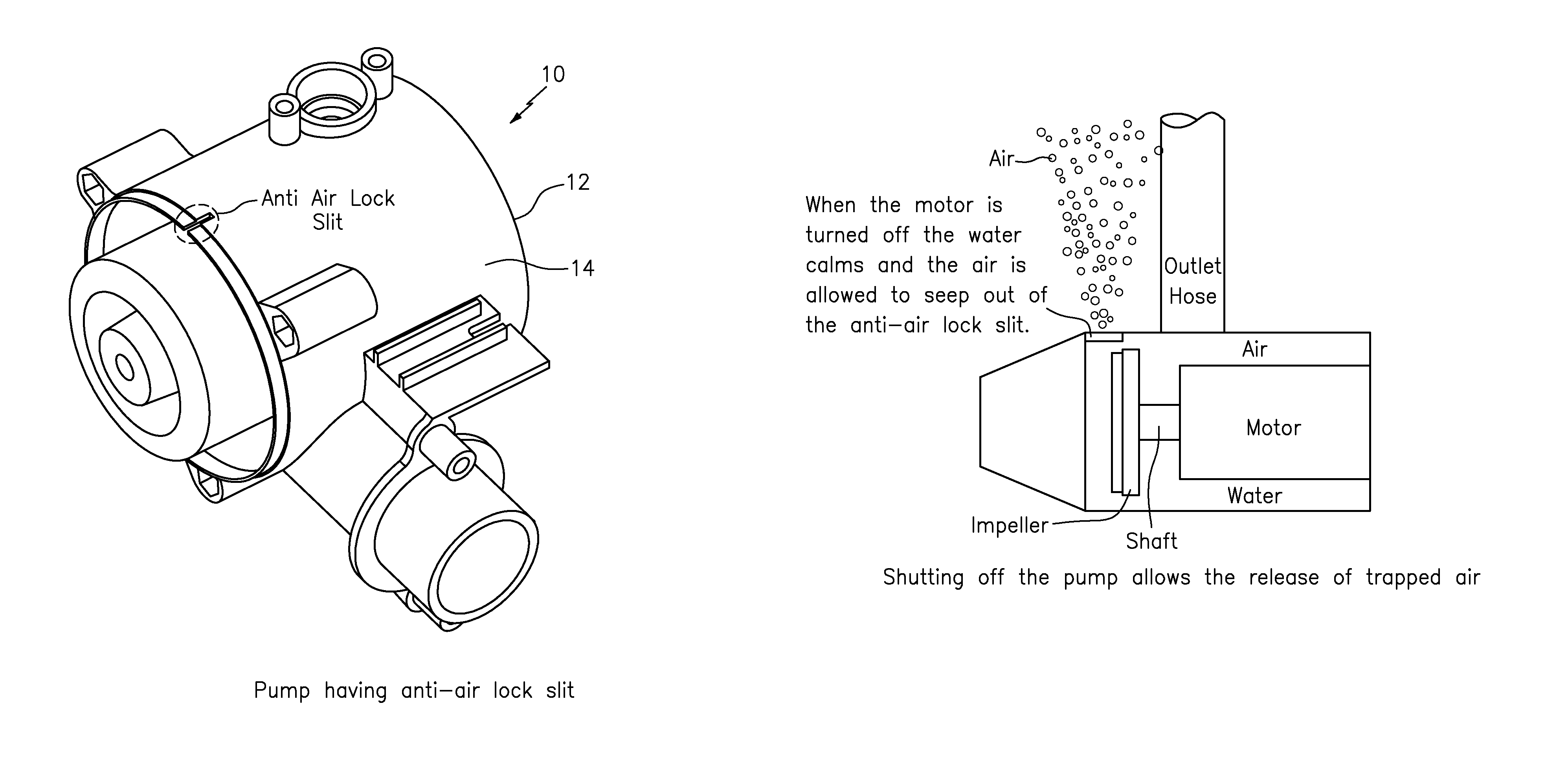
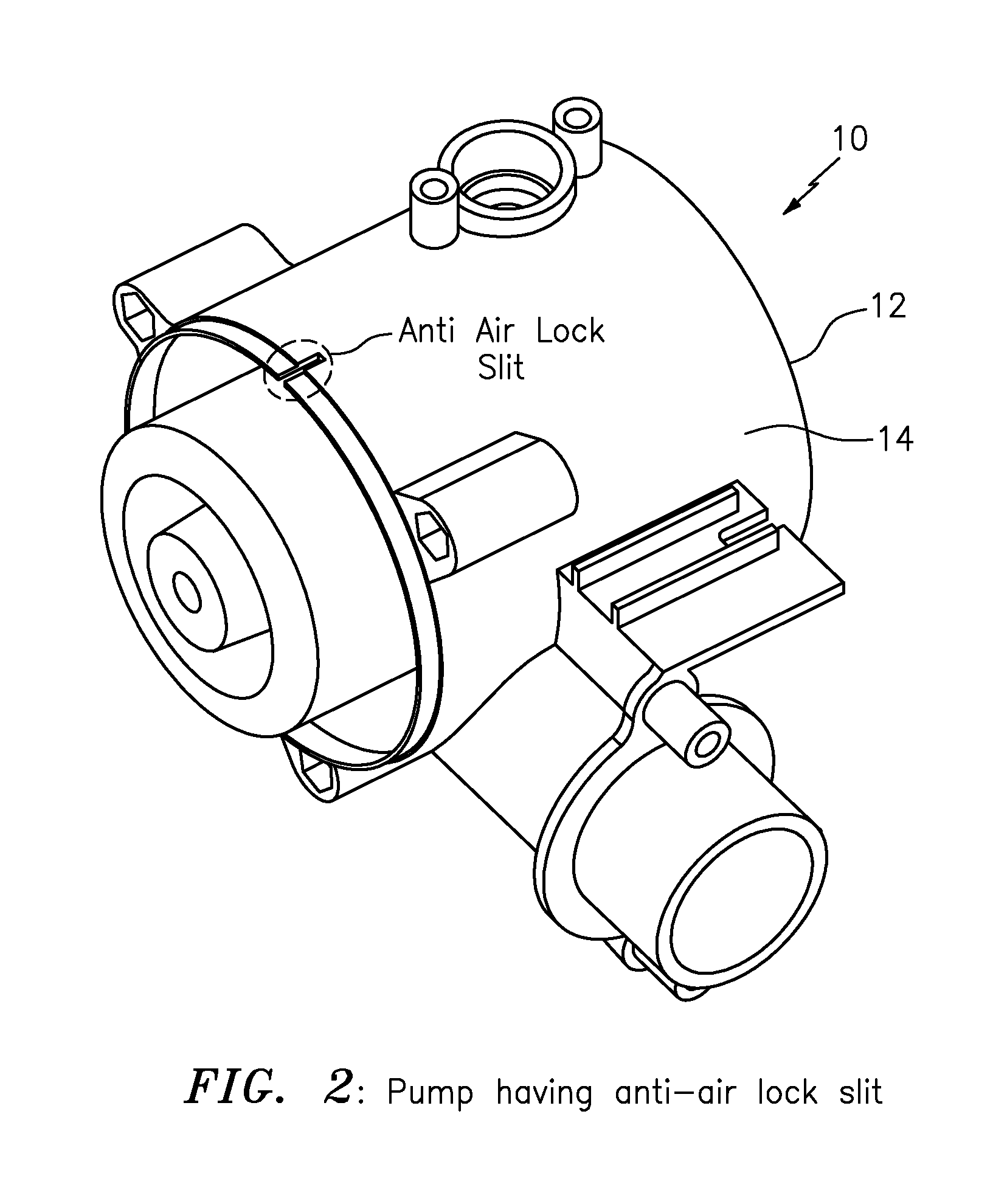
By way of example, FIG. 2 shows the pump 12 which may include an impeller housing 14 configured with at least one slit (aka "an anti air lock slit") at the top for trapped air to leave the impeller housing 14 once the pump 12 has been submerged. The pump 12 may take the form of a centrifugal pump, as well as other types or kinds of pumps either now known or later developed in the future. In FIG. 2, the slit may be configured substantially at the top of the impeller housing of the pump, although the scope of the invention is intended to include configuring the slit at other locations as long as trapped air can be released from inside the impeller housing 14. Moreover, the scope of the invention is not intended to be limited to any particular type, kind or configuration of the slit, or hole, as long as trapped air can leave or be released from the impeller housing once the pump has been submerged.
The control circuit 20 (see FIGS. 3 and 7) may be configured to cycle the pump 12 on and off for a predetermined number of cycles so that the trapped air will float to the top and be expelled out the slit when the pump 12 is cycled off. The cycling of the pump 12 on and off for a predetermined number of cycles at start-up is also known herein and referred to as either a stutter start anti-air lock start-up or system, and may also be referred to herein as an anti air-lock on/off start-up cycle. By way of example, the control circuit 20 (FIG. 7) may be arranged or configured inside or outside the pump 12 in FIG. 2, and the scope of the invention is not intended to be limited to the same.
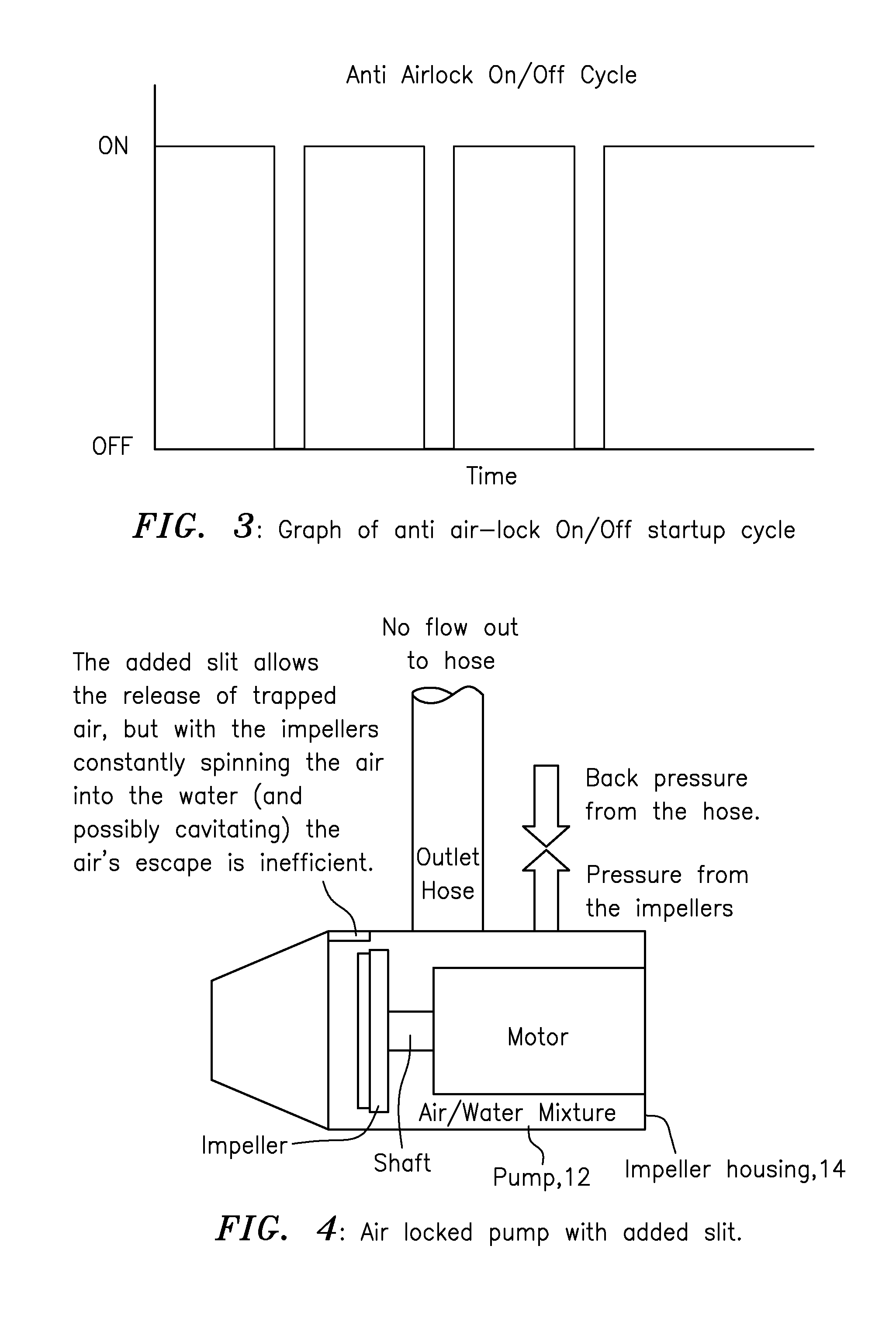
FIG. 3
By way of example, FIG. 3 shows a graph having an ON/OFF cycle for the pump 12 each time it is started. Upon powering the pump 12, the motor(s) will turn on for some time, and then off for some time, and this process may be repeated for a predetermined number of cycles after which the motor will remain on until the pump 12 is manually powered off. The scope of the invention is not intended to be limited to any particular number of ON/OFF cycles or the duration of the ON/OFF cycles. Based on that disclosed herein, a person skilled in the art, without undue experimentation, would be able configured the control circuit 20 to cycle the pump 12 on and off for a predetermined number of cycles so that the trapped air will float to the top and be expelled out the slit when the pump 12 is cycled off.
FIG. 4: Air Locked Pump with Added Slit
FIG. 4 shows the pumping system 10 according to some embodiment of the present invention, e.g., before the implementation of the anti air-lock on/off start-up cycle. In FIG. 4, the pump 12 is shown immersed in a fluid, such as water, indicated by a dark coloration in FIG. 4. The pump 12 has an added slit that may allow the release of trapped air, but with the impeller constantly spinning the air into the water (and possibly cavitating) so as to form an air/water mixture as shown as by a light gray coloring in FIG. 4, the escape of the air is inefficient. Similar to that shown in FIG. 1, and consistent with that shown in FIG. 4, the pressure from the impeller(s) is overcome by the back pressure from the outlet hose, so there is no meaningful flow, if any, out the outlet hose. In effect, the pumping system is, or may be considered, merely an air locked pump with an added slit.
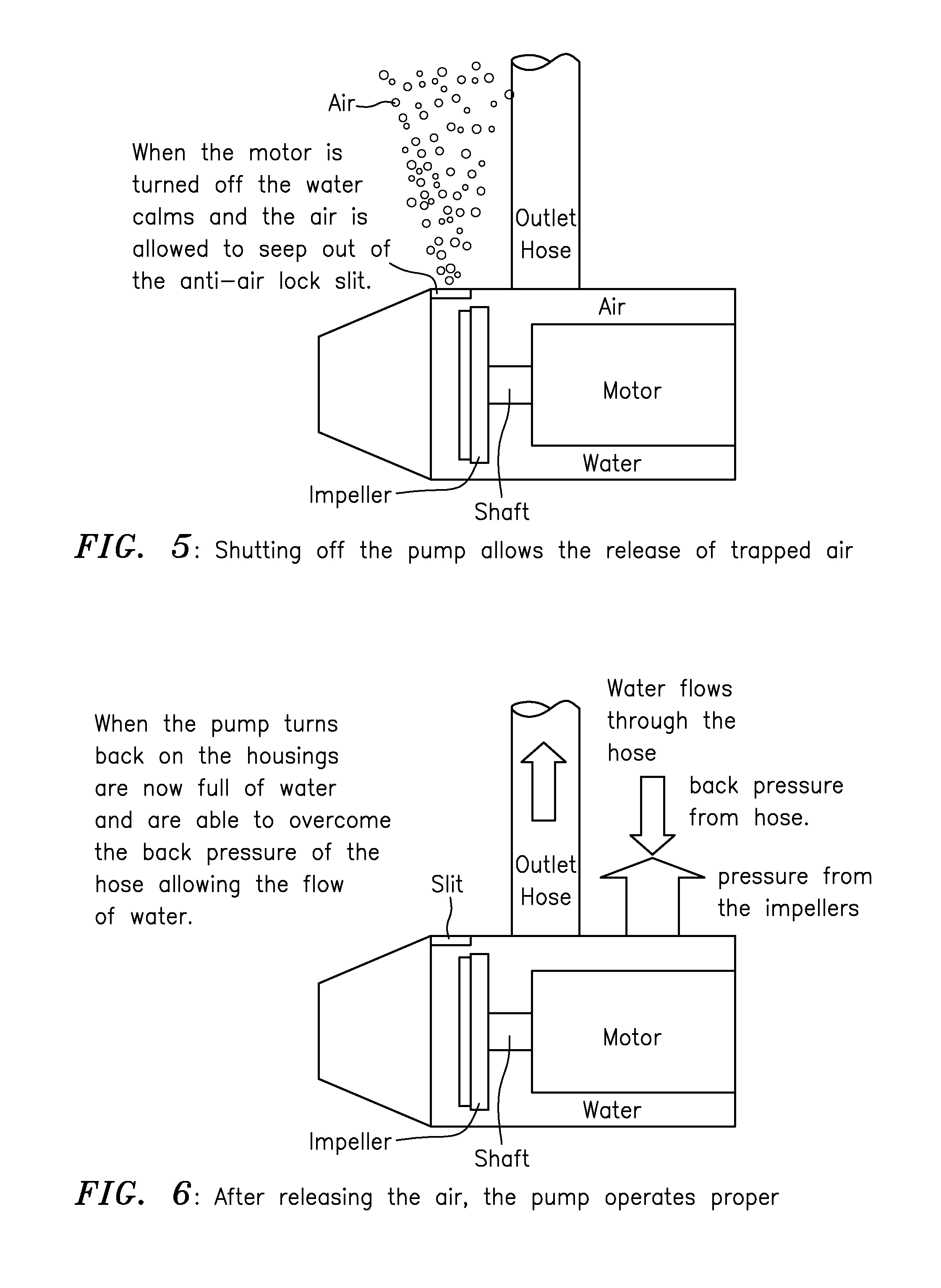
FIG. 5: Implementation of Anti Air-Lock On/Off Start-Up Cycle
In contrast to that in FIG. 4, FIG. 5 shows the pumping system 10 according to some embodiments of the present invention, e.g., when the pump 12 is turned off during the implementation of an anti air-lock on/off start-up cycle. In operation, when the motor is turned on, then turned off, the water (shown at the bottom of the impeller housing by a darker gray coloring) calms and the air (shown at the top of the impeller housing by a white coloring) is allowed to seep out of the anti air-lock slit. In effect, the turning on and shutting off of the pump allows the release of trapper air, which is shown as air bubbles floating to the top of the fluid in which the pump 12 is immersed.
FIG. 6: Pump Turned on After Anti Air-Lock On/Off Start-Up Cycle
FIG. 6 shows the pumping system 10 according to some embodiments of the present invention, e.g., when the pump is turned on after the implementation of the anti air-lock on/off start-up cycle, according to some embodiments of the present invention. When the pump turns back on, the housings are now full of water (as shown) and are able to overcome the back pressure of the hose allowing the flow of water. In contrast to that shown in FIG. 1, and consistent with that shown in FIG. 6, the pressure from the impellers overcomes the back pressure from the outlet hose, so there is water flow out and through the outlet hose. In effect, after releasing the air, the pump operates properly.
FIG. 7: Block Diagram of Pumping System
FIG. 7 shows the control circuit 20 that forms part of the pumping system generally indicated as 10 and that is arranged in relation to a power source 40. By way of example, the pumping system 10 may include a relay 30 coupled between the pump 12 and the control circuit 20, as shown. In operation, the control circuit 20 provides signaling to turn the relay 30 on/off in order to cycle the pump 12 on and off for the predetermined number of cycles so that the trapped air will float to the top and be expelled out the slit when the pump 12 is cycled off. By way of example, the relay 30 may be coupled directly to the motor of the pump 12, shown in FIGS. 4-6. Once the start-up process is complete, the control circuit 20 may be configured to leave the pump 12 on after the predetermined number of cycles.
Relays, and techniques for controlling and cycling such relays, are known in the art, and the scope of the invention is not intended to be limited to any particular type or kind thereof either now known or later developed in the future.
Embodiments are also envisioned in which the control circuit 20 is coupled directly to the motor of the pump 12 and to provide the signaling to turn the motor (see FIGS. 4-6) on/off in order to cycle the pump 12 on and off for the predetermined number of cycles so that the trapped air will float to the top and be expelled out the slit when the pump 12 is cycled off.
Implementation of the Functionality of the Control Circuit and Associated Signal Processor
The control circuit 20 may be implemented in, or form part of, a signal processor module having a signal processor, and/or a printed circuit board (PCB), or some combination thereof.
Printed circuit boards (PCBs) are known in the art, and the scope of the invention is not intended to be limited to any particular type or kind thereof either now known or later developed in the future for implementing the runtime on/off cycling functionality of the present invention.
By way of example, the functionality of the control circuit 20, the PCB, the associated signal processor, and/or any associated signal processing may be implemented using hardware, software, firmware, or a combination thereof, although the scope of the invention is not intended to be limited to any particular embodiment thereof. For example, in a typical software implementation, the signal processor may take the form of one or more microprocessor-based architectures having a processor or microprocessor, a random and/or read only access memory (RAM/ROM), where the RAM/ROM together forming at least part of the memory, input/output devices and control, data and address buses connecting the same. A person skilled in the art would be able to program such a microprocessor-based implementation with computer program code to perform the functionality described herein without undue experimentation. The scope of the invention is not intended to be limited to any particular implementation using technology either now known or later developed in the future. Moreover, the scope of the invention is intended to include the signal processor being a stand alone module, or in some combination with other circuitry for implementing another module. Moreover still, the scope of the invention is not intended to be limited to any particular type or kind of signal processor used to perform the signal processing functionality, or the manner in which the computer program code is programmed or implemented in order to make the signal processor operate. A person skilled in the art without undue experimentation would appreciate and understand how to develop or write a suitable software program or algorithm for running on, e.g., such a PCB-based control circuit, so as to implement the functionality set forth herein.
Such a PCB-based control circuit and/or the associated signal processor may include one or more other sub-modules for implementing other functionality that is known in the art, but does not form part of the underlying invention per se, and is not described in detail herein.
Centrifugal Pump
In one particular embodiment, the present invention may take the form of, or may be implemented in, a centrifugal pump encased in such a housing that directs the water projected from the pump's impeller into an exit tube. In the centrifugal pump, there exists, or may be configured, a small hole or slit formed in this casing or housing through which to expel the trapped air when the pump is submerged. The centrifugal pump and/or pumping system may include the control circuit like element 20 whose function is to cycle, e.g., the motor of the centrifugal pump on and off for some predetermined time upon powering of the unit or pumping system, consistent with that set forth herein.
The Pump 12
The pump 12, like that shown in FIGS. 2 and 4-7, may also include, e.g., other parts, elements, components, or circuits that do not form part of the underlying invention, including inlet ports, outlet ports, pressure transducers, wiring for coupling the motor to the control circuit 20, and are thus not identified and described in detail herein.
Moreover, pumps having motors and impeller arranged or configured thereon are known in the art, and the scope of the invention is not intended to be limited to any particular type or kind thereof either now known or later developed in the future.
Possible Applications
Possible applications are envisioned to include any type or kind of pump or rotary equipment that may be submerged and contain trapped air, e.g., in its housing or impeller housing, including but not limited to centrifugal pumps or other types or kinds of submersible pumps either now known or later developed in the future.
SCOPE OF THE INVENTION
Although described in the context of particular embodiments, it will be apparent to those skilled in the art that a number of modifications and various changes to these teachings may occur. Thus, while the invention has been particularly shown and described with respect to one or more preferred embodiments thereof, it will be understood by those skilled in the art that certain modifications or changes, in form and shape, may be made therein without departing from the scope and spirit of the invention as set forth above.
* * * * *
D00000
D00001
D00002
D00003
D00004
D00005
XML
uspto.report is an independent third-party trademark research tool that is not affiliated, endorsed, or sponsored by the United States Patent and Trademark Office (USPTO) or any other governmental organization. The information provided by uspto.report is based on publicly available data at the time of writing and is intended for informational purposes only.
While we strive to provide accurate and up-to-date information, we do not guarantee the accuracy, completeness, reliability, or suitability of the information displayed on this site. The use of this site is at your own risk. Any reliance you place on such information is therefore strictly at your own risk.
All official trademark data, including owner information, should be verified by visiting the official USPTO website at www.uspto.gov. This site is not intended to replace professional legal advice and should not be used as a substitute for consulting with a legal professional who is knowledgeable about trademark law.