Mechanical teleoperated device comprising an interchangeable distal instrument
Beira
U.S. patent number 10,265,129 [Application Number 15/116,509] was granted by the patent office on 2019-04-23 for mechanical teleoperated device comprising an interchangeable distal instrument. This patent grant is currently assigned to DistalMotion SA. The grantee listed for this patent is DistalMotion SA. Invention is credited to Ricardo Daniel Rita Beira.


| United States Patent | 10,265,129 |
| Beira | April 23, 2019 |
Mechanical teleoperated device comprising an interchangeable distal instrument
Abstract
Disclosed is a mechanical teleoperated device comprising i) a handle (30) placed in a proximal part of the device, having a plurality of handle links interconnected by respective handle joints, ii) an end effector (31) placed in a distal part of the device, having a plurality of end-effector links interconnected by respective end-effector joints, iii) a transmission system arranged to kinematically connect the end effector to the handle such that movements of the end effector correspond to movements of the handle, comprising at least one arrangement of a plurality of rotatable elements (41a-d) coaxially mounted together about an axis and arranged to rotate independently from each other, b) first transmission means comprising driving elements (62a-c) which are arranged to actuate in rotation of the plurality of rotatable elements (41a-d) based upon movements of the handle, c) second transmission means comprising driven elements (63a-c) which are arranged to be driven by rotation of the plurality of rotatable elements resulting in movement of the end effector links, wherein the transmission system is configured for removably coupling together the first and second transmission means wherein each driven element is removably coupled to one corresponding rotatable element.
| Inventors: | Beira; Ricardo Daniel Rita (Lausanne, CH) | ||||||||||
|---|---|---|---|---|---|---|---|---|---|---|---|
| Applicant: |
|
||||||||||
| Assignee: | DistalMotion SA (Epalinges,
CH) |
||||||||||
| Family ID: | 52423713 | ||||||||||
| Appl. No.: | 15/116,509 | ||||||||||
| Filed: | January 26, 2015 | ||||||||||
| PCT Filed: | January 26, 2015 | ||||||||||
| PCT No.: | PCT/EP2015/051473 | ||||||||||
| 371(c)(1),(2),(4) Date: | August 03, 2016 | ||||||||||
| PCT Pub. No.: | WO2015/113933 | ||||||||||
| PCT Pub. Date: | August 06, 2015 |
Prior Publication Data
| Document Identifier | Publication Date | |
|---|---|---|
| US 20160346053 A1 | Dec 1, 2016 | |
Foreign Application Priority Data
| Feb 3, 2014 [CH] | 138/14 | |||
| Mar 12, 2014 [EP] | 14159025 | |||
| Mar 18, 2014 [CH] | 408/14 | |||
| Current U.S. Class: | 1/1 |
| Current CPC Class: | A61B 34/35 (20160201); A61B 34/30 (20160201); A61B 34/37 (20160201); A61B 34/71 (20160201); A61B 2090/506 (20160201); A61B 2017/00477 (20130101) |
| Current International Class: | A61B 17/00 (20060101); A61B 34/00 (20160101); A61B 34/30 (20160101); A61B 34/35 (20160101); A61B 34/37 (20160101); A61B 90/50 (20160101) |
References Cited [Referenced By]
U.S. Patent Documents
| 2774488 | December 1956 | Goertz |
| 2846084 | August 1958 | Goertz et al. |
| 4756655 | July 1988 | Jameson |
| 5147357 | September 1992 | Rose et al. |
| 5207114 | May 1993 | Salisbury et al. |
| 5209747 | May 1993 | Knoepfler |
| 5304203 | April 1994 | El-Mallawany et al. |
| 5308358 | May 1994 | Bond et al. |
| 5330502 | July 1994 | Hassler et al. |
| 5368606 | November 1994 | Marlow et al. |
| 5383888 | January 1995 | Zvenyatsky et al. |
| 5484435 | January 1996 | Fleenor et al. |
| 5599151 | February 1997 | Daum et al. |
| 5603723 | February 1997 | Aranyi et al. |
| 5631973 | May 1997 | Green |
| 5649956 | July 1997 | Jensen et al. |
| 5710870 | January 1998 | Ohm et al. |
| 5716352 | February 1998 | Viola et al. |
| 5735874 | April 1998 | Measamer et al. |
| 5784542 | July 1998 | Ohm et al. |
| 5797900 | August 1998 | Madhani et al. |
| 5810716 | September 1998 | Mukherjee et al. |
| 5810805 | September 1998 | Sutcu et al. |
| 5828813 | October 1998 | Ohm |
| 5908436 | June 1999 | Cuschieri et al. |
| 5951587 | September 1999 | Qureshi et al. |
| 6026701 | February 2000 | Reboulet |
| 6197017 | March 2001 | Brock et al. |
| 6206903 | March 2001 | Ramans |
| 6233504 | May 2001 | Das et al. |
| 6281651 | August 2001 | Haanpaa et al. |
| 6358249 | March 2002 | Chen et al. |
| 6361534 | March 2002 | Chen et al. |
| 6364879 | April 2002 | Chen et al. |
| 6371952 | April 2002 | Madhani et al. |
| 6394998 | May 2002 | Wallace et al. |
| 6435794 | August 2002 | Springer |
| 6554844 | April 2003 | Lee et al. |
| 6786896 | September 2004 | Madhani et al. |
| 6788999 | September 2004 | Green |
| 6850817 | February 2005 | Green |
| 6852107 | February 2005 | Wang et al. |
| 6902560 | June 2005 | Morley et al. |
| 6951535 | October 2005 | Ghodoussi et al. |
| 6991627 | January 2006 | Madhani et al. |
| 6994708 | February 2006 | Manzo |
| 7090637 | August 2006 | Danitz et al. |
| 7101363 | September 2006 | Nishizawa et al. |
| 7204836 | April 2007 | Wagner et al. |
| 7232440 | June 2007 | Dumbauld et al. |
| 7306597 | December 2007 | Manzo |
| 7316681 | January 2008 | Madhani et al. |
| 7338513 | March 2008 | Lee et al. |
| 7364582 | April 2008 | Lee |
| 7398707 | July 2008 | Morley et al. |
| 7481824 | January 2009 | Boudreaux et al. |
| 7608039 | October 2009 | Todd |
| 7615002 | November 2009 | Rothweiler et al. |
| 7615067 | November 2009 | Lee et al. |
| 7674255 | March 2010 | Braun |
| 7699855 | April 2010 | Anderson et al. |
| 7819894 | October 2010 | Mitsuishi et al. |
| 7824401 | November 2010 | Manzo et al. |
| 7828798 | November 2010 | Buysse et al. |
| 7976458 | July 2011 | Stefanchik et al. |
| 8048084 | November 2011 | Schneid |
| 8105320 | January 2012 | Manzo |
| 8114017 | February 2012 | Bacher |
| 8137263 | March 2012 | Marescaux et al. |
| 8224485 | July 2012 | Unsworth |
| 8287469 | October 2012 | Stefanchik et al. |
| 8292889 | October 2012 | Cunningham et al. |
| 8306656 | November 2012 | Schaible et al. |
| 8308738 | November 2012 | Nobis et al. |
| 8332072 | December 2012 | Schaible et al. |
| 8336751 | December 2012 | Scirica |
| 8347754 | January 2013 | Veltri et al. |
| 8353898 | January 2013 | Lutze et al. |
| 8357161 | January 2013 | Mueller |
| 8382742 | February 2013 | Hermann et al. |
| 8403832 | March 2013 | Cunningham et al. |
| 8418904 | April 2013 | Wenchell et al. |
| 8496152 | July 2013 | Viola |
| 8523900 | September 2013 | Jinno et al. |
| 8540748 | September 2013 | Murphy et al. |
| 8562592 | October 2013 | Conlon et al. |
| 8568444 | October 2013 | Cunningham |
| 8579176 | November 2013 | Smith et al. |
| 8591397 | November 2013 | Berkelman et al. |
| 8603077 | December 2013 | Cooper et al. |
| 8617203 | December 2013 | Stefanchik et al. |
| 8663270 | March 2014 | Donnigan et al. |
| 8668689 | March 2014 | Dumbauld et al. |
| 8668702 | March 2014 | Awtar et al. |
| 8696666 | April 2014 | Sanai et al. |
| 8709000 | April 2014 | Madhani et al. |
| 8768509 | July 2014 | Unsworth |
| 8792688 | July 2014 | Unsworth |
| 8801752 | August 2014 | Fortier et al. |
| 8818560 | August 2014 | Kishi |
| 8821480 | September 2014 | Burbank |
| 8828046 | September 2014 | Stefanchik et al. |
| 8845517 | September 2014 | Russo |
| 8845622 | September 2014 | Paik et al. |
| 8870867 | October 2014 | Walberg et al. |
| 8887979 | November 2014 | Mastri et al. |
| 8894674 | November 2014 | Balanev et al. |
| 8930027 | January 2015 | Schaible et al. |
| 8945098 | February 2015 | Seibold et al. |
| 8961499 | February 2015 | Paik et al. |
| 8961514 | February 2015 | Garrison |
| 8968187 | March 2015 | Kleyman et al. |
| 8989844 | March 2015 | Cinquin et al. |
| 8992564 | March 2015 | Jaspers |
| 9023015 | May 2015 | Penna |
| 9033998 | May 2015 | Schaible et al. |
| 9044238 | June 2015 | Orszulak |
| 9084606 | July 2015 | Greep |
| 9113861 | August 2015 | Martin et al. |
| 9149339 | October 2015 | Unsworth |
| 9307894 | April 2016 | Von Grunberg et al. |
| 9480531 | November 2016 | Von Grunberg |
| 9696700 | July 2017 | Beira et al. |
| 2002/0040217 | April 2002 | Jinno |
| 2002/0049367 | April 2002 | Irion et al. |
| 2002/0072736 | June 2002 | Tierney et al. |
| 2003/0155747 | August 2003 | Bridges |
| 2003/0208186 | November 2003 | Moreyra |
| 2004/0049205 | March 2004 | Lee et al. |
| 2004/0236316 | November 2004 | Danitz et al. |
| 2004/0253079 | December 2004 | Sanchez |
| 2005/0096502 | May 2005 | Khalili |
| 2005/0204851 | September 2005 | Morley et al. |
| 2005/0240078 | October 2005 | Kwon et al. |
| 2006/0043698 | March 2006 | Bridges |
| 2006/0178559 | August 2006 | Kumar et al. |
| 2006/0183975 | August 2006 | Saadat et al. |
| 2006/0219065 | October 2006 | Jinno et al. |
| 2006/0235436 | October 2006 | Anderson et al. |
| 2006/0253109 | November 2006 | Chu |
| 2007/0088340 | April 2007 | Brock et al. |
| 2007/0137371 | June 2007 | Devengenzo et al. |
| 2007/0156123 | July 2007 | Moll et al. |
| 2007/0208375 | September 2007 | Nishizawa et al. |
| 2007/0299387 | December 2007 | Williams et al. |
| 2008/0046122 | February 2008 | Manzo et al. |
| 2008/0058776 | March 2008 | Jo et al. |
| 2008/0071208 | March 2008 | Voegele et al. |
| 2008/0103492 | May 2008 | Morley et al. |
| 2008/0177285 | July 2008 | Brock et al. |
| 2008/0243106 | October 2008 | Coe |
| 2008/0314181 | December 2008 | Schena |
| 2009/0036902 | February 2009 | Dimaio et al. |
| 2009/0198253 | August 2009 | Omori |
| 2009/0216249 | August 2009 | Jinno et al. |
| 2009/0247821 | October 2009 | Rogers |
| 2009/0248039 | October 2009 | Cooper et al. |
| 2009/0299141 | December 2009 | Downey et al. |
| 2010/0004508 | January 2010 | Naito et al. |
| 2010/0023025 | January 2010 | Zeiner et al. |
| 2010/0121347 | May 2010 | Jaspers |
| 2010/0160929 | June 2010 | Rogers et al. |
| 2010/0160940 | June 2010 | Lutze et al. |
| 2010/0170519 | July 2010 | Romo et al. |
| 2010/0305595 | December 2010 | Hermann |
| 2010/0318099 | December 2010 | Itkowitz et al. |
| 2010/0318101 | December 2010 | Choi |
| 2011/0087236 | April 2011 | Stokes et al. |
| 2011/0213346 | September 2011 | Morley et al. |
| 2011/0230867 | September 2011 | Hirschfeld et al. |
| 2011/0275901 | November 2011 | Shelton, IV |
| 2011/0276084 | November 2011 | Shelton, IV |
| 2011/0290854 | December 2011 | Timm et al. |
| 2011/0301419 | December 2011 | Craft et al. |
| 2012/0027762 | February 2012 | Schofield |
| 2012/0031114 | February 2012 | Mueller et al. |
| 2012/0095298 | April 2012 | Stefanchik et al. |
| 2012/0116163 | May 2012 | Lutze et al. |
| 2012/0132018 | May 2012 | Tang et al. |
| 2012/0143173 | June 2012 | Steege et al. |
| 2012/0158014 | June 2012 | Stefanchik et al. |
| 2012/0209292 | August 2012 | Devengenzo et al. |
| 2012/0253326 | October 2012 | Kleyman |
| 2012/0277762 | November 2012 | Lathrop et al. |
| 2012/0289973 | November 2012 | Prisco |
| 2012/0289974 | November 2012 | Rogers et al. |
| 2012/0296341 | November 2012 | Seibold et al. |
| 2013/0123805 | May 2013 | Park et al. |
| 2013/0144274 | June 2013 | Stefanchik et al. |
| 2013/0245643 | September 2013 | Woodard et al. |
| 2013/0245647 | September 2013 | Martin et al. |
| 2013/0282027 | October 2013 | Woodard et al. |
| 2013/0304083 | November 2013 | Kaercher et al. |
| 2014/0005681 | January 2014 | Gee et al. |
| 2014/0018447 | January 2014 | McGovern et al. |
| 2014/0018780 | January 2014 | Hirscheld |
| 2014/0076088 | March 2014 | Berkelman et al. |
| 2014/0114481 | April 2014 | Ogawa et al. |
| 2014/0142595 | May 2014 | Awtar et al. |
| 2014/0166023 | June 2014 | Kishi |
| 2014/0180308 | June 2014 | Von Grunberg |
| 2014/0188091 | July 2014 | Vidal et al. |
| 2014/0188159 | July 2014 | Steege |
| 2014/0200561 | July 2014 | Ingmanson et al. |
| 2014/0207150 | July 2014 | Rosa et al. |
| 2014/0230595 | August 2014 | Butt et al. |
| 2014/0249546 | September 2014 | Shvartsberg et al. |
| 2014/0263541 | September 2014 | Leimbach et al. |
| 2014/0263553 | September 2014 | Leimbach et al. |
| 2014/0276956 | September 2014 | Crainich et al. |
| 2014/0350570 | November 2014 | Lee |
| 2015/0057499 | February 2015 | Erden et al. |
| 2015/0057702 | February 2015 | Edmondson et al. |
| 2015/0060517 | March 2015 | Williams |
| 2015/0066018 | March 2015 | Doll et al. |
| 2015/0105821 | April 2015 | Ward et al. |
| 2015/0142018 | May 2015 | Sniffin et al. |
| 2015/0150575 | June 2015 | Hartoumbekis et al. |
| 2015/0250547 | September 2015 | Fukushima et al. |
| 2015/0265355 | September 2015 | Prestel et al. |
| 2016/0022365 | January 2016 | Jensen et al. |
| 2016/0051274 | February 2016 | Howell et al. |
| 2016/0151115 | June 2016 | Karguth et al. |
| 2016/0374766 | December 2016 | Schuh |
| 2017/0273749 | September 2017 | Grover |
| 2018/0055583 | March 2018 | Schuh |
| 101584594 | Nov 2009 | CN | |||
| 101637402 | Feb 2010 | CN | |||
| 101732093 | Jun 2010 | CN | |||
| 103717355 | Apr 2014 | CN | |||
| 43 03 311 | Aug 1994 | DE | |||
| 19652792 | May 1999 | DE | |||
| 10314827 | Apr 2004 | DE | |||
| 10314828 | Jul 2004 | DE | |||
| 10 2012 222 755 | Jun 2014 | DE | |||
| 10 2014 205 036 | Sep 2015 | DE | |||
| 10 2014 205 159 | Sep 2015 | DE | |||
| 0 595 291 | May 1994 | EP | |||
| 0 621 009 | Oct 1994 | EP | |||
| 0 677 275 | Oct 1995 | EP | |||
| 1 254 642 | Nov 2002 | EP | |||
| 1 279 371 | Dec 2004 | EP | |||
| 1 886 630 | Feb 2008 | EP | |||
| 1 889 579 | Feb 2008 | EP | |||
| 2 058 090 | May 2009 | EP | |||
| 1 977 677 | Aug 2009 | EP | |||
| 2 095 778 | Sep 2009 | EP | |||
| 1 889 583 | Apr 2011 | EP | |||
| 2 377 477 | May 2012 | EP | |||
| 2 473 119 | Jul 2012 | EP | |||
| 2 305 144 | Oct 2012 | EP | |||
| 2 044 893 | Jul 2013 | EP | |||
| 2 653 110 | Oct 2013 | EP | |||
| 2 679 192 | Jan 2014 | EP | |||
| 2 736 680 | Jun 2014 | EP | |||
| 2 777 561 | Sep 2014 | EP | |||
| 2 837 340 | Feb 2015 | EP | |||
| 2 837 354 | Feb 2015 | EP | |||
| 2 554 131 | Aug 2015 | EP | |||
| 2 979 657 | Feb 2016 | EP | |||
| 0 969 899 | Sep 1964 | GB | |||
| 2004-041580 | Feb 2004 | JP | |||
| 2007-290096 | Nov 2007 | JP | |||
| 2008-104620 | May 2008 | JP | |||
| 2009-018027 | Jan 2009 | JP | |||
| 20110032444 | Mar 2011 | KR | |||
| 20130031403 | Mar 2013 | KR | |||
| WO-82/00611 | Mar 1982 | WO | |||
| WO-03/067341 | Aug 2003 | WO | |||
| WO-03/086219 | Oct 2003 | WO | |||
| WO-2004/052171 | Jun 2004 | WO | |||
| WO-2005/009482 | Feb 2005 | WO | |||
| WO-2005/046500 | May 2005 | WO | |||
| WO-2006/086663 | Apr 2006 | WO | |||
| WO-2007/133065 | Nov 2007 | WO | |||
| WO-2008/130235 | Oct 2008 | WO | |||
| WO-2009/091497 | Jul 2009 | WO | |||
| WO-2009/095893 | Aug 2009 | WO | |||
| WO-2009/145572 | Dec 2009 | WO | |||
| WO-2009/157719 | Dec 2009 | WO | |||
| WO-2010/019001 | Feb 2010 | WO | |||
| WO-2010/030114 | Mar 2010 | WO | |||
| WO-2010/050771 | May 2010 | WO | |||
| WO-2010/083480 | Jul 2010 | WO | |||
| WO-2010/096580 | Aug 2010 | WO | |||
| WO-2010/130817 | Nov 2010 | WO | |||
| WO-2012/020386 | Feb 2012 | WO | |||
| WO-2012/049623 | Apr 2012 | WO | |||
| WO-2014/012780 | Jan 2014 | WO | |||
| WO-2014/018447 | Jan 2014 | WO | |||
| WO-2014/067804 | May 2014 | WO | |||
| WO-2014/094716 | Jun 2014 | WO | |||
| WO-2014/094717 | Jun 2014 | WO | |||
| WO-2014/094718 | Jun 2014 | WO | |||
| WO-2014/094719 | Jun 2014 | WO | |||
| WO-2014/145148 | Sep 2014 | WO | |||
| WO-2014/156221 | Oct 2014 | WO | |||
| WO-2014/201010 | Dec 2014 | WO | |||
| WO-2014/201538 | Dec 2014 | WO | |||
| WO-2015/081946 | Jun 2015 | WO | |||
| WO-2015/081947 | Jun 2015 | WO | |||
| WO-2015/088647 | Jun 2015 | WO | |||
| WO-2015/088655 | Jun 2015 | WO | |||
| WO-2015/111475 | Jul 2015 | WO | |||
| WO-2015/113933 | Aug 2015 | WO | |||
| WO-2015/129383 | Aug 2015 | WO | |||
| WO-2015/139674 | Sep 2015 | WO | |||
| WO-2016/083189 | Jun 2016 | WO | |||
| WO-01/6189284 | Dec 2016 | WO | |||
| WO-2016/189284 | Dec 2016 | WO | |||
| WO-2017/064301 | Apr 2017 | WO | |||
| WO-2017/064303 | Apr 2017 | WO | |||
| WO-2017/064305 | Apr 2017 | WO | |||
| WO-2017/064306 | Apr 2017 | WO | |||
Other References
|
Abbott, et al., "Design of an Endoluminal Notes Robotic System," IEEE/RSJ International Conference on Intelligent Robots and Systems, San Diego, CA, pp. 410-416 (2007). cited by applicant . Aesculap Surgical Technologies, Aesculap.RTM. Caiman.RTM., Advanced Bipolar Seal and Cut Technology Brochure, 6 pages (retrieved Aug. 31, 2015). cited by applicant . Arata, et al., "Development of a dexterous minimally-invasive surgical system with augmented force feedback capability," IEEE/RSJ International Conference on Intelligent Robots and Systems, pp. 3207-3212 (2005). cited by applicant . cavuo{hacek over (g)}lu, et al., "Laparoscopic Telesurgical Workstation," IEEE Transactions on Robotics and Automation,(15)4:728-739 (1999). cited by applicant . Dachs, et al., "Novel Surgical Robot Design: Minimizing the Operating Envelope Within the Sterile Field," 28th International Conference, IEEE Engineering in Medicine Biology Society, New York, pp. 1505-1508 (2006). cited by applicant . Dario, et al., "Novel Mechatronic Tool for Computer-Assisted Arthroscopy," IEEE Transactions on Information Technology in Biomedicine, 4(1):15-29 (Mar. 2000). cited by applicant . Focacci, et al., "Lightweight Hand-held Robot for Laparoscopic Surgery," IEEE International Conference on Robotics & Automation, Rome, Italy, pp. 599-604 (2007). cited by applicant . Guthart, et al., "The Intuitive.TM. Telesurgery System: Overview and Application," IEEE International Conference on Robotics & Automation, San Francisco, CA, pp. 618-621 (2000). cited by applicant . Ikuta, et al., "Development of Remote Microsurgery Robot and New Surgical Procedure for Deep and Narrow Space," IEEE International Conference on Robotics & Automation, Taipei, Taiwan, pp. 1103-1108 (2003). cited by applicant . Ikuta, et al., "Hyper Redundant Miniature Manipulator `Hyper Finger` for Remote Minimally Invasive Surgery in Deep Area," IEEE International Conference on Robotics & Automation, Taipei, Taiwan, pp. 1098-1102 (2003). cited by applicant . International Search Report & Written Opinion dated Feb. 2, 2017 in Int'l PCT Patent Appl. Serial No. PCT/IB2016/001286. cited by applicant . International Search Report & Written Opinion dated Jan. 18, 2013 in Int'l PCT Patent Appl Serial No. PCT/IB2012/053786. cited by applicant . International Search Report dated Jan. 18, 2013 in Int'l PCT Patent Appl Serial No. PCT/IB2012/053786. cited by applicant . International Search Report dated Mar. 23, 2012 in Int'l PCT Patent Appl Serial No. PCT/IB2011/054476. cited by applicant . Ishii, et al., "Development of a New Bending Mechanism and Its Application to Robotic Forceps Manipulator," IEEE International Conference on Robotics & Automation, Rome, Italy, pp. 238-243 (2007). cited by applicant . International Search Report & Written Opinion dated May 23, 2016 in Int'l PCT Patent Appl Serial No. PCT/IB2015/002524. cited by applicant . International Search Report & Written Opinion dated Mar. 30, 2015 in Int'l PCT Patent Appl Serial No. PCT/EP2015/051473. cited by applicant . International Search Report & Written Opinion dated Apr. 26, 2016 in Int'l PCT Patent Appl Serial No. PCT/IB2015/002512. cited by applicant . International Search Report & Written Opinion dated May 24, 2016 in Int'l PCT Patent Appl Serial No. PCT/IB2015/002487. cited by applicant . International Search Report & Written Opinion dated Jun. 10, 2016 in Int'l PCT Patent Appl Serial No. PCT/IB2015/002533. cited by applicant . International Search Report & Written Opinion dated Jun. 13, 2016 in Int'l PCT Patent Appl Serial No. PCT/IB2015/002493. cited by applicant . International Search Report & Written Opinion dated Aug. 25, 2016 in Int'l PCT Patent Appl Serial No. PCT/IB2016/000542. cited by applicant . International Search Report & Written Opinion dated Sep. 2, 2016 in Int'l PCT Patent Appl Serial No. PCT/IB2016/000543. cited by applicant . Kobayashi, et al., "Small Occupancy Robotic Mechanisms for Endoscopic Surgery," International Conference on Medical Image Computing and Computer assisted Interventions, pp. 75-82 (2002). cited by applicant . Mayer, et al., "The Endo[PA]R System for Minimally Invasive Robotic Surgery," IEEE/RSJ International Conference on Intelligent Robots and Systems, Sendai, Japan, pp. 3637-3642 (2004). cited by applicant . Mitsuishi, et al., "Development of a Remote Minimally Invasive Surgical System with Operational Environment Transmission Capability," IEEE International Conference on Robotics & Automation, Taipei, Taiwan, pp. 2663-2670 (2003). cited by applicant . Nakamura, et al., "Multi-DOF Forceps Manipulator System for Laparoscopic Surgery-Mechanism miniaturized & Evaluation of New Interface," 4th International Conference on Medical Image Computing and Computer assisted Interventions (MICCAI2001), pp. 606-613 (2001). cited by applicant . Peirs, et al., "Design of an advanced tool guiding system for robotic surgery," IEEE International Conference on Robotics & Automation, Taipei, Taiwan, pp. 2651-2656 (2003). cited by applicant . Salle, et al., "Optimal Design of High Dexterity Modular MIS Instrument for Coronary Artery Bypass Grafting," IEEE International Conference on Robotics & Automation, New Orleans, LA, pp. 1276-1281 (2004). cited by applicant . Seibold, et al., "Prototype of Instrument for Minimally Invasive Surgery with 6-Axis Force Sensing Capability," IEEE International Conference on Robotics & Automation, Barcelona, Spain, pp. 496-501 (2005). cited by applicant . Simaan et al., "Dexterous System for Laryngeal Surgery: Multi-Backbone Bending Snake-like Slaves for Teleoperated Dexterous Surgical Tool Manipulation," IEEE International Conference on Robotics & Automation, New Orleans, LA, pp. 351-357 (2004). cited by applicant . Stryker.RTM., Endoscopy, Take a Look Around, Ideal Eyes.TM. FFD122 HD, Articulating Laparoscope Brochure, 2 pages (2009). cited by applicant . Swiss Search Report dated Jun. 4, 2012 in Swiss Patent Application No. CH 00702/12. cited by applicant . Tavakoli, et al., "Force Reflective Master-Slave System for Minimally Invasive Surgery," IEEE/RSJ International Conference on Intelligent Robots and Systems, Las Vegas, NV, pp. 3077-3082 (2003). cited by applicant . Taylor, et al., "Steady-Hand Robotic System for Microsurgical Augmentation," The International Journal of Robotics Research, 18(12):1201-1210 (1999). cited by applicant . www.cttc.co/technologies/maestro-non-robotic-dexterous-laproscopic-instrum- ent-writs-providing-seven-degrees, "Maestro: Non-Robotic Dexterous Laproscopic Instrument With a Wrist Providing Seven Degrees of Freedom", accessed Nov. 12, 2015, 4 pages. cited by applicant . Yamashita, et al., "Development of Endoscopic Forceps Manipulator Using Multi-Slider Linkage Mechanisms," The 1st Asian Symposium on Computer Aided Surgery-Robotic and Image-Guided Surgery, Ibaraki, Japan, 4 pages (2005). cited by applicant . Zeus, "Robotic Surgical System" available at http://allaboutroboticsurgery.com/zeusrobot.html. cited by applicant. |
Primary Examiner: Boes; Terence
Attorney, Agent or Firm: Foley & Lardner LLP Bolten; Christopher C. Pisano; Nicola A.
Claims
The invention claimed is:
1. A mechanical teleoperated device comprising: a handle having a plurality of handle links interconnected by respective handle joints; an end effector spaced apart from the handle and having a plurality of end-effector links interconnected by respective end-effector joints; a transmission system that kinematically couples the end effector to the handle such that movements of the end effector correspond to movements of the handle, the transmission system comprising: a plurality of independently rotatable elements coaxially mounted about a single axis; a plurality of driving elements arranged to cause rotation of the plurality of independently rotatable elements responsive to movements of the handle; and a plurality of driven elements arranged to cause movement of the end effector links responsive to rotation of the plurality of independently rotatable elements, wherein the transmission system is configured for removably coupling the plurality of driving elements to the plurality of driven elements such that each one of the plurality of driven elements is removably coupled to a corresponding one of the plurality of independently rotatable elements.
2. The mechanical teleoperated device of claim 1, wherein a segment of each driven element is removably connected to a corresponding independently rotatable element such that each segment is guided along a path within a plane which is substantially perpendicular to the axis about which the corresponding independently rotatable element is arranged to rotate.
3. The mechanical teleoperated device of claim 2, wherein the path extends along a circular trajectory having a center point coincident with the single axis.
4. The mechanical teleoperated device of claim 1, wherein the single axis coincides with the axis of a joint of the mechanical teleoperated device.
5. The mechanical teleoperated device of claim 1, wherein each driven element is anchored to a mating receptacle pivotally mounted about the single axis, wherein each corresponding independently rotatable element comprises a complementary mating part configured to be removably mounted inside the mating receptacle.
6. The mechanical teleoperated device of claim 5, wherein each mating part is mounted on a support connected to a corresponding independently rotatable element.
7. The mechanical teleoperated device of claim 6, wherein the mating receptacles and corresponding mating parts are housed inside a first housing, the first housing comprising first and second complementary housing parts removably mounted together.
8. The mechanical teleoperated device of claim 7, wherein the mating receptacles are mounted inside the first complementary housing part and wherein the complementary mating parts are mounted inside the second complementary housing part.
9. The mechanical teleoperated device of claim 1, wherein the plurality of independently rotatable elements are arranged into two groups, wherein a first group of independently rotatable elements are coaxially mounted to rotate about a first axis of rotation and a second group of independently rotatable elements are coaxially mounted to rotate about a second axis of rotation.
10. The mechanical teleoperated device of claim 9, wherein each driving element is connected to an independently rotatable element of the first group and to a corresponding independently rotatable element of the second group.
11. The mechanical teleoperated device of claim 10, wherein the second axis is coincident with the axis of a joint of the mechanical teleoperated device.
12. The mechanical teleoperated device of claim 11, wherein the transmission system further comprises links kinematically connected to an actuable element of the handle.
13. The mechanical teleoperated device of claim 12, wherein a segment of each link is anchored to a corresponding rotatable element of the second group.
14. The mechanical teleoperated device of claim 1, wherein the mechanical teleoperated device has a master-slave configuration, comprising a slave unit, having a plurality of slave links interconnected by respective slave joints, and a master unit having a plurality of master links interconnected by respective master joints.
15. The mechanical teleoperated device of claim 14, wherein the kinematic model of plurality of slave links and respective slave joints of the slave unit is identical to the kinematic model of the plurality of master links and respective master joints of the mater unit.
Description
CROSS-REFERENCE TO RELATED APPLICATIONS
This application is a national phase of International PCT Patent Application No. PCT/EP2015/051473, filed Jan. 26, 2015, which claims priority to Switzerland Patent Application No. CH00408/14, filed Mar. 18, 2014, EPO Patent Application No. 14159025.7, filed Mar. 12, 2014, and Switzerland Patent Application No. CH00138/14, filed Feb. 3, 2014, the entire contents of each of which are incorporated herein by reference.
FIELD OF THE INVENTION
The present invention relates to the field of remotely actuated mechanical systems. In particular embodiments, the invention relates to a mechanical teleoperated device for use primarily in surgical procedures and comprising an interchangeable distal instrument. Certain embodiments have particular applicability in minimally invasive surgical procedures. The present invention is also suitable for any remotely actuated application requiring dexterous manipulation with high stiffness and precision along with force feedback. Examples of such applications include assembly manipulation, manipulation in narrow places, manipulation in dangerous or difficult environments, and manipulation in contaminated or clean-room environments.
BACKGROUND OF THE INVENTION
Numerous environments and applications call for remote actuation with mechanically teleoperated devices. These applications include fine manipulation in assembly tasks, manipulation in narrow places, manipulation in dangerous or contaminated environments, manipulation in clean-room or sterile environments and manipulation in surgical environments, whether open field or minimally invasive. While these applications vary along parameters such as precise tolerances and typical end user, each demands many of the same features from a mechanically teleoperated system, such as the ability to carry out dexterous manipulation with high stiffness and precision along with force feedback.
Surgical applications are now discussed in more detail as a representative example of an application for a mechanically teleoperated device system where known devices exist but significant shortcomings are evident in the current state of the art.
Open surgery is still the standard technique for most surgical procedures. It has been used by the medical community for several decades and consists of performing the surgical tasks by making a long incision in the abdomen or other area of the body, through which traditional surgical tools are inserted. However, due to the long incision, this approach is extremely invasive for patients, resulting in substantial blood loss during surgery and, typically, long and painful recovery periods in a hospital setting.
In order to reduce the invasiveness of open surgery, laparoscopy, a minimally invasive technique, was developed. Instead of a single long incision, several small incisions are made in the patient through which long and thin surgical instruments and endoscopic cameras are inserted. Because of the minimally invasive nature of the procedure, this technique reduces blood loss and pain and shortens hospital stays. When performed by experienced surgeons, this technique can attain clinical outcomes similar to open surgery. However, despite the above-mentioned advantages, laparoscopy requires extremely advanced surgical skill to manipulate the rigid and long instrumentation. The entry incision acts as a point of rotation, decreasing the freedom for positioning and orientating the instruments inside the patient. The movements of the surgeon's hand about this incision are inverted and scaled-up relative to the instrument tip ("fulcrum effect"), which reduces dexterity and sensitivity and magnifies the tremors of the surgeon hands. In addition, the long and straight instruments force the surgeon to work in an uncomfortable posture for hands, arms and body, which can be tremendously tiring during several hours of an operation. Therefore, due to these drawbacks of laparoscopic instrumentation, these minimally invasive techniques are mainly limited to use in simple surgeries, while only a small minority of surgeons is able to use them in complex procedures.
To overcome these limitations, surgical robotic systems were developed to provide an easier-to-use approach to complex minimally invasive surgeries. By means of a computerized robotic interface, these systems enable the performance of remote laparoscopy where the surgeon sits at a console manipulating two master manipulators to perform the operation through several small incisions. Like laparoscopy, the robotic approach is also minimally invasive, bringing the above-mentioned advantages over open surgery in terms of pain, blood loss, and recovery time. In addition, it also offers better ergonomy for the surgeon compared to open and laparoscopic techniques. However, although being technically easier, robotic surgery brings several negative aspects. A major disadvantage of these systems relates to the extremely high complexity of the existing robotic devices, which comprise complex mechatronic systems, leading to huge costs of acquisition and maintenance, which are not affordable for the majority of surgical departments worldwide. Another drawback of these systems comes from the fact that current surgical robots are large, competing for precious space within the operating room environment and significantly increasing preparation time. Access to the patient is thus impaired, which, together with a general lack of force-feedback, raises safety concerns.
WO9743942, WO9825666 and U.S.2010011900 disclose a robotic tele-operated surgical instrument, designed to replicate surgeons' hand movements inside the patient's body. By means of a computerized, robotic interface, it enables the performance of remote laparoscopy, wherein the surgeon sits at a console manipulating two joysticks to perform the operation through several small incisions. However, this system does not have autonomy or artificial intelligence, being essentially a sophisticated tool fully controlled by the surgeon. The control commands are transmitted between the robotic master and robotic slave by a complex computer-controlled mechatronic system, which is extremely costly to produce and maintain and difficult to use for the hospital staff.
WO2012049623 describes a mechanical manipulator for surgical instruments with a master-slave configuration and including remote actuation of a distal end effector. However, the system described therein does not provide for an interchangeable instrument.
WO2013014621 describes a mechanical teleoperated device for remote manipulation which comprises master-slave configuration including a slave unit driven by a kinematically equivalent master unit such that each part of the slave unit mimics the movement of each corresponding part of the master unit. Although the mechanical transmission system is well adapted to the device, cables passing through an axial joint are twisted when the device is operating, which can force the cables to rub against each other. This increases wear on the cables over time and increases friction in the overall mechanical transmission.
Accordingly, an aim of the present invention is to provide a mechanical teleoperated device comprising an interchangeable distal instrument. This device could be designed for use in a surgical environment such that the interchangeable distal instruments would be surgical instruments. However, one of skill in the art will realize that the device could also be deployed in other applications where complex, remote manipulation is required and wherein interchangeable instruments would be useful for different manipulation tasks.
Another aim of the present invention is to provide a mechanical teleoperated system with an improved transmission system. In such a system, the transmission system, and particularly the joints, would be designed such that cables do not rub against each other, thus reducing wear and tear.
SUMMARY OF THE INVENTION
These aims and other advantages are achieved through a mechanical teleoperated device for remote manipulation designed to naturally replicate the operator's hand movements in the distal area where the manipulation must occur. The mechanical teleoperated device may comprise a slave unit, configured to be driven by a master unit, which is preferably kinematically equivalent to the slave unit. The slave unit has a plurality of slave links interconnected by respective slave joints and comprises a proximal part and a distal part (also referred to as a distal instrument) connected distally to one of the slave joints, referred to as the interface slave joint. More particularly, this interface slave joint of the slave unit may have a coaxial configuration, connecting a proximal and a distal link of the slave unit in such a manner that these two adjoining links are axially rotatable with respect to each other about the axis of the coaxial joint. The master unit comprises a plurality of master links interconnected by respective master joints, and a corresponding interface master joint.
An articulated handle is connected to the master unit for operating the mechanical teleoperated device and an articulated end-effector is connected to the distal extremity of the distal instrument. The mechanical teleoperated device further comprises a transmission system arranged to kinematically connect the equivalent degrees-of-freedom of the master and slave units, including the degrees-of-freedom of the end-effector to the degrees-of-freedom of the handle such that said end-effector replicates the movements of the handle when the mechanical teleoperated device is operated.
The transmission system comprises (i) at least one arrangement of a plurality of rotatable elements coaxially mounted together and coaxial to the axis of the interface slave joint of the slave unit and arranged to rotate independently from each other; (ii) first transmission means integrated into the proximal part of the slave unit and comprising driving cables or the like which are arranged to actuate in rotation each one of the rotatable elements of the said at least one arrangement; and (iii) second transmission means integrated into the distal instrument and comprising driven cables or the like which are arranged to be driven by the rotation of each one of the corresponding rotatable elements of the at least one arrangement of a plurality of rotatable elements.
The transmission system according to the invention is advantageously configured for removably coupling together the first and second transmission means of the respective proximal and distal parts of the slave unit. In this arrangement, each driven cable of said second transmission means is removably connected, by means of additional elements, to one corresponding rotatable element of said at least one arrangement of a plurality of rotatable elements in order to provide a user-friendly interchangeable and modular tooling/instrument system for use with the mechanical teleoperated device.
According to one embodiment of the invention, a segment of each driven cable of the second transmission means is removably connected to one corresponding rotatable element of the at least one arrangement of a plurality of rotatable elements. Each of these segments is guided along a path within a plane which is substantially perpendicular to the axis about which the rotatable elements of the at least one arrangement of a plurality of rotatable elements are able to rotate. This path preferably extends along a circular trajectory, whose center point is coincident with the rotatable elements' axis.
According to another embodiment of the invention, each driven cable of said second transmission means is anchored to a mating receptacle pivotally mounted about the axis of the interface slave joint of the slave unit. Each corresponding rotatable element of the at least one arrangement of a plurality of rotatable elements comprises a complementary mating part removably mounted inside the corresponding mating receptacle.
According to a further embodiment of the invention, each complementary mating part is mounted on a pointer which is connected to one corresponding rotatable element. These pointers are able to rotate around the axis of the interface slave joint and may be angularly offset from each other so that their angular amplitude of movement allows the full-range actuation of the end-effector articulations.
According to a further embodiment of the invention, the mating receptacles and corresponding mating parts are housed inside a slave housing. The slave housing comprises two complementary housing parts removably mounted against each other. Said mating receptacles are mounted inside one complementary housing part which is connected to the distal part of the slave unit whereas said complementary mating parts are mounted inside the other complementary housing part which is connected to the proximal part of the slave unit.
According to another embodiment of the invention, the transmission system comprises two arrangements of a plurality of rotatable elements, wherein rotatable elements of the first arrangement are coaxially mounted together so that each one is able to rotate about the axis of an interface slave joint of the slave unit, and wherein rotatable elements of the second arrangement are coaxially mounted together to rotate about each other, being collinear with the axis of an interface master joint of the master unit. In this configuration, each driving cable of the first transmission means is connected to one rotatable element of the first arrangement of the slave unit and to one corresponding rotatable element of the second arrangement of the master unit such that rotation of each rotatable element of said second arrangement rotates the corresponding rotatable element of said first arrangement.
According to yet another embodiment of the invention, two or more teleoperated devices, as defined above, can be set to work together, enabling the user to perform bi-manual manipulation. In addition, two or more telemanipulators can be mounted on a movable and articulated station, so that they can be easily moved on the ground from one place to the other and their working position and orientation can be tuned in the 3D space.
BRIEF DESCRIPTION OF THE FIGURES
The invention will be better understood according to the following detailed description of several embodiments of the invention with reference to the attached figures, in which:
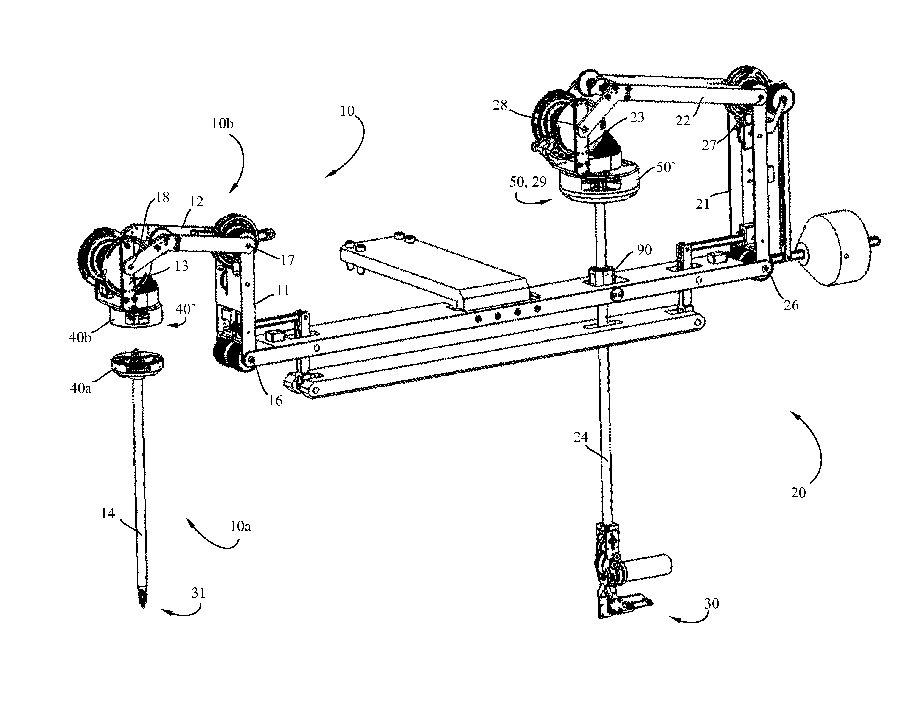
FIG. 1 shows a perspective view of a mechanical teleoperated device according to the invention;
FIG. 2 shows a schematic view of the transmission system of the mechanical teleoperated device of FIG. 1;
FIG. 3 shows a schematic view of the transmission system of FIG. 1 comprising first, second and third transmission means;
FIGS. 4, 5 and 6 show a schematic view of the transmission system for the transmission of each degree-of-freedom of the handle to the end-effector;
FIG. 7 shows a perspective view of a detachable distal instrument;
FIG. 8 shows a perspective view of a lower part of the slave housing of the first arrangement of the transmission system containing mating receptacles;
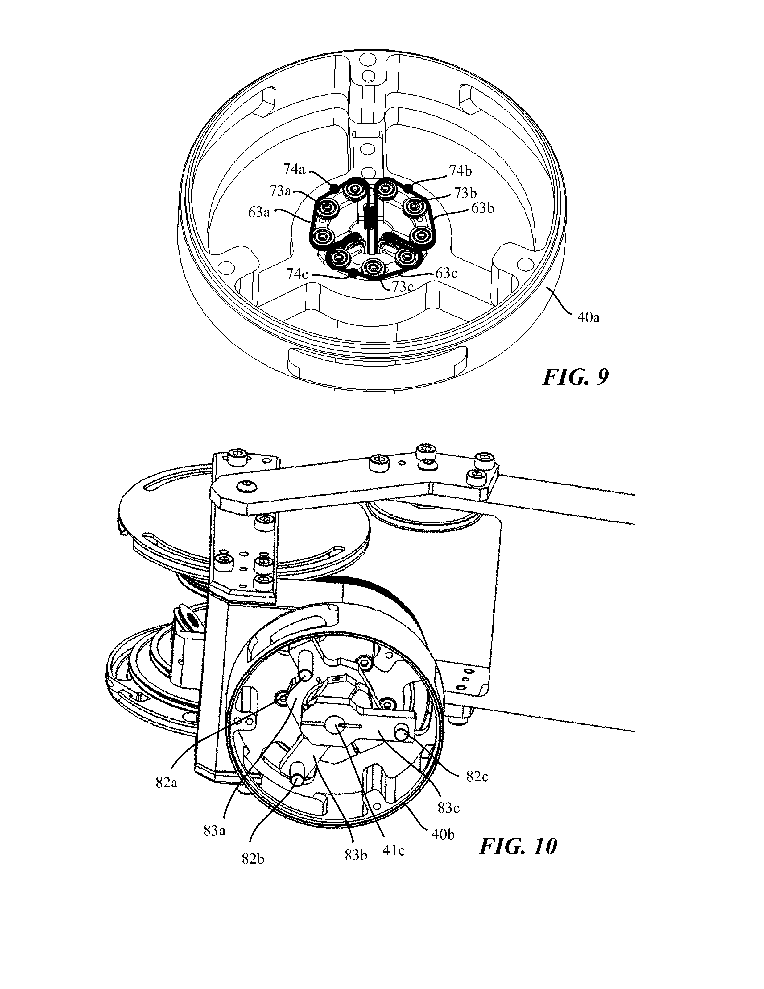
FIG. 9 shows a perspective view of the guiding means of the slave housing of FIG. 8;
FIG. 10 shows an upper part of the slave housing containing complementary mating parts arranged to be removably mounted inside the corresponding mating receptacle of FIG. 8;
FIGS. 11a, 11b and 11c show three different views of the distal part coupling with the proximal part of the slave unit of the mechanical teleoperated device of FIG. 1, and
FIG. 12 shows an exemplary embodiment comprising two identical mechanical teleoperated devices of FIG. 1 mounted on an articulated and movable station, namely a mechanical telemanipulator for surgical procedures.
DETAILED DESCRIPTION OF THE INVENTION
A mechanical telemanipulator, which may be used in minimally invasive surgical procedures or in other applications, constructed in accordance with an embodiment of the present invention, is described herein, and is seen generally in FIG. 12. This manipulator comprises preferably two identical mechanical teleoperated devices, as shown for example in FIG. 1, mounted on an articulated and movable station 110 (FIG. 12) and configured to be operated independently from the other. Each mechanical teleoperated device of FIG. 1, as conceptually described in WO2013/014621, comprises, on the one hand, a master-slave configuration, having a slave unit 10 driven by a kinematically equivalent master unit 20 and, on the other hand, mechanical constraint means 90 such that each part of the slave unit 10 mimics the movement of each corresponding part of the master unit 20 without deviating, during operation of the device, from a remote-center-of-motion (RCM) as shown in FIG. 3. However, in other embodiments of the current invention, the mechanical teleoperated device may not have a remote-center-of-motion (RCM). Given that the two mechanical teleoperated devices are structurally and functionally identical, the description hereafter will refer to one mechanical teleoperated device only as shown particularly in FIGS. 1 to 6.
Referring more particularly to FIG. 3, the slave unit 10 comprises a plurality of slave links 11, 12, 13, 14 interconnected by respective slave joints 16, 17, 18, 19. An articulated end-effector 31 is mounted at the distal end of the slave link 14 which is rotatably connected to the adjoining link 13 through an coaxial joint 19 such that the two adjoining links 13, 14 are coaxially rotatable with respect to each other about the axis of the axial joint 19. The remaining slave joints 16, 17, 18 of the slave unit 10 are of the type of so-called pivot-joint which connects two adjoining links (e.g. pivot joint 17 connecting link 12 with link 13) in order to be angularly actuable with respect to each other within a plane perpendicular to the axis of rotation of said pivot-joint. The master unit 20 comprises a structural and kinematic configuration identical to the slave unit 10. More particularly, the master unit 20 comprises a corresponding plurality of master links 21, 22, 23, 24 interconnected by respective master joints 26, 27, 28, 29. One of these joints is a coaxial joint 29 while the other joints are pivot-joints 26, 27, 28. An articulated handle 30 is connected at the distal end of a master link 24 of the master unit 20 for operating the mechanical teleoperated device.
Upward and downward movements applied to the handle 30 by the operator when the mechanical teleoperated device is in the neutral position of FIG. 3 translate the master link 24 along its longitudinal axis through the mechanical constraint means 90 whereas frontward and backward movements applied on the handle rotate the master link 24 about an axis parallel to the axis of each pivot-joint. Each one of these movements or a combination thereof generates angular displacement of the master joints 26, 27, 28, 29 of the master unit 20 wherein said angular displacement of each master joint causes, through mechanical transmission, an identical angular displacement of the corresponding slave joint 16, 17, 18, 19 of the slave unit 10. The kinematic connection between each pivot-joint 26, 27, 28 of the master unit 20 with the corresponding pivot joint 16, 17, 18 of the slave unit 10, is achieved by pulley-routed cables which are each arranged to be anchored to two corresponding pulleys rotatably mounted around a shaft whose axis is coincident with the axis the corresponding pivot-joint. Kinematic connections between each pivot-joint 16, 17, 18 of the slave unit 10 with the corresponding pivot-joint 26, 27, 28 of the master unit 20 are described in more details in the aforementioned PCT application (WO2013/014621). In this configuration, the kinematic model of the chain formed by the plurality of slave links 11, 12, 13, 14 and respective slave joints 16, 17, 18, 19 of the slave unit 10 is identical to the kinematic model of the chain formed by the plurality of master links 21, 22, 23, 24 and respective master joints 26, 27, 28, 29 of the mater unit 20.
As schematically shown in FIG. 2, the handle 30 is configured to actuate three degrees-of-freedom of the end effector 31 by a transmission system adapted to kinematically connect three pulleys 30a, 30b, 30c of the handle 30 with three corresponding pulley 31a, 31b, 31c of the end-effector 31. In this way, angular displacement of each pulley of the handle 30, when the teleoperated surgical device is operating, is replicated by the corresponding pulley of the end-effector 31. The latter is configured such that counter-rotation of both pulleys 31b, 31c in one direction rotates jaws 32a, 32b in opposite direction away from each other to open the grip of the jaws while counter-rotation of both pulleys 31b, 31c in the other direction rotates the jaws 32a, 32b in opposite directions toward each other to close the grip and maintain a gripping force of the jaws. The working tips of the jaws 32a, 32b have a surface for gripping and may be used, for example, in forceps or cautery applications. Alternately, "gripping" which closes the jaws may be a cutting action when the tips of the jaws 32a, 32b are blades that cooperatively cut as a scissors. Gripping can thus perform different functions depending the nature of the end-effector 31. This end-effector is further configured to pivot about the axis of its pulley 31a when the latter is actuated by the cable-driven system according to the invention.
Still referring to FIG. 2, the transmission system according to this preferred embodiment comprises a first arrangement 40 of three rotatable elements 41a, 41b, 41c coaxially mounted together about the axis 19a of the interface slave joint of the slave unit and a second arrangement 50 of three rotatable elements 51a, 51b, 51c coaxially mounted together about the axis 29a of the interface master joint of the master unit. The rotatable element 41d comprises the driven pulley that actuates the interface slave joint 19 of the slave unit 10, being rigidly attached to the slave link 14. The rotatable element 51d comprises the driving pulley that actuates the interface master joint 29 of the master unit 20, being rigidly attached to the master link 24. Rotatable elements 41a, 41b, 41c of the first arrangement 40 are partly housed inside a slave housing 40' while rotatable elements 51a, 51b, 51c of the second arrangement 50 are partly housed inside a master housing 50'. As shown in FIG. 1, the slave and master housings 40', 50' are connected respectively to a distal link 14 of the slave unit 10 and to a corresponding master link 24 of the master unit 20. The slave housing 40' is further connected to the rotatable element 41d whereas the master housing 50' is further connected to the corresponding rotatable element 51d.
The transmission system as shown in FIG. 2 further comprises first transmission means which have three cables 62a, 62b, 62c or similar structure which are each arranged to connect one rotatable element 51a, 51b, 51c of the second arrangement with one corresponding rotatable element 41a, 41b, 41c of first arrangement 40 such that rotation of each rotatable element 51a, 51b, 51c of second arrangement 50 actuates the corresponding cable which rotates in turn the equivalent rotatable element 41a, 41b, 41c of first arrangement 40.
Referring now to FIGS. 4 to 6, the transmission system comprises second transmission means which have three driven cables 63a, 63b, 63c or similar structures which are each arranged to be anchored on a corresponding pulley 31a, 31b, 31c of the end-effector 31 to enable angular displacement of these pulleys about their respective pivotal connection. These driven cables extends axially through the slave link 14 to be removably anchored to a corresponding rotatable element 41a, 41b, 41c of the first arrangement 40 of the slave unit 10. The removable connection of each driven cable to the corresponding rotatable element will be described in details subsequently.
The transmission system further comprises third transmission means which have three cables 61a, 61b, 61c or similar structures which are each arranged to be anchored on a corresponding pulley 30a, 30b, 30c of the handle 30 in order to be driven by angular displacement of these pulleys about their respective pivotal connection generated by the actuation of handle 30. Each of these cables 61a, 61b, 61c extends axially along the master link 24 to be anchored to a corresponding rotatable element 51a, 51b, 51c of the second arrangement 50 of the master unit 20. FIG. 2 partly shows in more details how this type of connection is achieved. Each cable 61a, 61b, 61c (only cables 61a and 61c are visible) are partially guided within a plane which is preferably perpendicular to the axis of the axial joint 29 of the master unit 20 and along a substantially circular path through an angle of less than 120 degrees (on the current embodiment). A segment 75a, 75c (75b is not visible in FIG. 2) of each cables is attached to a corresponding pointer 76a, 76b, 76c, wherein these pointers are coaxially mounted jointly with respective rotatable element 51a, 51b, 51c, and are superposed and angularly offset from each other.
According to the configuration of the transmission system, angular displacement of each pulley 30a, 30b, 30c of the handle 30 about their respective pivotal connection, during operation of the mechanical teleoperated device, drives the corresponding cable 61a, 61b, 61c of the third transmission means which causes the angular displacement of the corresponding rotatable element 51a, 51b, 51c of the second arrangement 50 about the axis of the interface slave joint 29 of the master unit 20. Rotation of each one of these rotatable elements 51a, 51b, 51c drives the corresponding cable 62a, 62b, 62c of the first transmission means which causes the angular displacement of the equivalent rotatable element 41a, 41b, 41c of the first arrangement 40 about the axis of the interface slave joint 19 of the slave unit 10. Rotation of each one of these rotatable elements 41a, 41b, 41c causes in turn the angular displacement of the corresponding pulley 31a, 31b, 31c of the end-effector 31 by means of the corresponding driven cable 63a, 63b, 63c of the second transmission means. The remaining two rotatable elements 41d, 51d of respective slave and master units 10, 20 are connected together by means of cable 62d such that axial rotation of the master link 24 rotates the corresponding slave link 14 about its longitudinal axis.
Due to this particular configuration, the transmission system is advantageously arranged to avoid twisting of the cables, when the master link 24 and the corresponding slave link 14 are coaxially rotating. Wear and tear of the cables resulting from prolonged use of the mechanical teleoperated device are therefore significantly reduced.
Referring now to FIGS. 8, 9 and 10, the transmission system according to the invention comprises a coupling/decoupling mechanism for removably connecting each driven cable 63a, 63b, 63c of the second transmission means with the corresponding cable 62a, 62b, 62c of the first transmission means in order to provide a user-friendly interchangeable and modular tooling system to the mechanical teleoperated device. To this end, lower and upper parts 40a, 40b of the slave housing 40' are removably secured against each other preferably by means of screws to allow the user to structurally disconnect the distal part 10a (FIG. 7) from the proximal part 10b of the slave unit 10 as particularly shown in FIG. 1.
With reference to FIG. 9, the coupling/decoupling device of the transmission system comprises guiding means 73a, 73b, 73c within the lower part 40a of the slave housing. Each of these guiding means 73a, 73b, 73c are preferably in the form of a series of rollers arranged to guide a segment 74a, 74b, 74c of each cable 63a, 63b, 63c of the second transmission means within a plane which is substantially perpendicular to the axis of the interface slave joint 19 of the slave unit 10 and along a substantially circular path through a certain angular range. In other embodiments of the same invention, instead of being composed by a series of rollers, the guiding means may comprise non-moving elements or surfaces in order to guide the segment 74a, 74b, 74c of each cable 63a, 63b, 63c of the second transmission means within their path. Each segment 74a, 74b, 74c of each one of these cables is anchored to a mating receptacle 81a, 81b, 81c pivotally mounted about the axis 19a of said interface slave joint 19 of the slave unit 10 as shown in FIG. 8. As can be seen in FIG. 10, a complementary mating part 82a, 82b, 82c, preferably in the form of a connecting pin, is mounted on respective supports 83a, 83b, 83c which are coaxially arranged jointly with respective rotatable element of the first arrangement. These supports 83a, 83b, 83c which are preferably in the form of pointers are superposed and angularly offset from each other. Each connecting pin 82a, 82b, 82c is adapted to be removably mounted inside the corresponding mating receptacle 81a, 81b, 81c as particularly shown in FIG. 11c.
According to the transmission system, the ratio of Rs/Rm (FIG. 2) equates to the ratio of Ds/Dm wherein: i) Rs is the radial distance between the axis of the interface slave joint 19 of the slave unit 10 and one anchored segment 73a, 73b, 73c of one driven cable 63a, 63b, 63c of the second transmission means; ii) Rm is the radial distance between the axis of the interface slave joint 29 of the master unit 20 and one anchored segment of one cable 61a, 61b, 61c of the third transmission means; iii) Ds is the diameter of one corresponding pulley 31, 31b, 31c of the end-effector 31; and iv) Dm is the diameter of one corresponding pulley 30a, 30b, 30c of the handle 30.
The configuration of the mechanical teleoperated device according to the invention allows the operator to easily remove the distal part 10a, comprising at its distal end the end-effector 31, and to replace it with another distal part comprising any type of end-effector such as scissors, scalpels, cutters, needle holders or any other surgical accessories.
Although the transmission system as disclosed in this preferred embodiment comprises cables, its particular configuration is not limited to this embodiment. For example, the present invention may also encompasses other flexible and non-flexible drive elements such as rods, linkages or the like which could be arranged to achieve the same functionality set forth herein.
Moreover, although the transmission system of the mechanical teleoperated device according to the preferred embodiment comprises first, second and third transmission means comprising each three cables to actuate three degrees of freedom of the end-effector when the handle is operated, the scope of the invention also covers configurations with first and second transmission means only such that their respective cables circumvents only joint 19 of the slave unit to allow detachment of the distal part 10a from the proximal part 10b of the slave unit 10. Transmission means in excess of three comprising each a distinct set of cables can also be envisaged to cover embodiments in which the master and slave units comprise each several coaxial joints.
While this invention has been particularly shown and described with references to particular embodiments thereof, it will be understood by those skilled in the art that various changes in form and details may be made therein without departing from the spirit and scope of the invention as defined by the appended claims. For example the scope of the invention includes configurations where at least the first and the third transmission means comprise N cables for the transmission of N degrees-of-freedom of the handle to the end-effector, where N can be for example 2, 4 or 5. In addition, the transmission system disclosed according to the embodiments described herein can be adapted to any teleoperated device which does not necessarily comprise a kinematically equivalent master-slave configuration.
* * * * *
References
D00000
D00001
D00002
D00003
D00004
D00005
D00006
D00007
D00008
P00001
XML
uspto.report is an independent third-party trademark research tool that is not affiliated, endorsed, or sponsored by the United States Patent and Trademark Office (USPTO) or any other governmental organization. The information provided by uspto.report is based on publicly available data at the time of writing and is intended for informational purposes only.
While we strive to provide accurate and up-to-date information, we do not guarantee the accuracy, completeness, reliability, or suitability of the information displayed on this site. The use of this site is at your own risk. Any reliance you place on such information is therefore strictly at your own risk.
All official trademark data, including owner information, should be verified by visiting the official USPTO website at www.uspto.gov. This site is not intended to replace professional legal advice and should not be used as a substitute for consulting with a legal professional who is knowledgeable about trademark law.