Tensionable constructs with multi-limb locking mechanism through single splice and methods of tissue repair
Dooney, Jr. , et al.
U.S. patent number 10,265,060 [Application Number 14/831,511] was granted by the patent office on 2019-04-23 for tensionable constructs with multi-limb locking mechanism through single splice and methods of tissue repair. This patent grant is currently assigned to Arthrex, Inc.. The grantee listed for this patent is Arthrex, Inc.. Invention is credited to Peter S. Borden, Thomas Dooney, Jr., Peter J. Dreyfuss, Alan M. Hirahara.


| United States Patent | 10,265,060 |
| Dooney, Jr. , et al. | April 23, 2019 |
Tensionable constructs with multi-limb locking mechanism through single splice and methods of tissue repair
Abstract
Systems and methods for soft tissue to bone repairs, without knot tying. Soft tissue repair systems include self-cinching constructs with a fixation device, a flexible strand with multiple flexible limbs, and a shuttle/pull device attached to the flexible strand to shuttle the multiple flexible limbs through the flexible strand and form a locking splice.
| Inventors: | Dooney, Jr.; Thomas (Naples, FL), Hirahara; Alan M. (Gold River, CA), Borden; Peter S. (Palos Verdes Estates, CA), Dreyfuss; Peter J. (Naples, FL) | ||||||||||
|---|---|---|---|---|---|---|---|---|---|---|---|
| Applicant: |
|
||||||||||
| Assignee: | Arthrex, Inc. (Naples,
FL) |
||||||||||
| Family ID: | 58156900 | ||||||||||
| Appl. No.: | 14/831,511 | ||||||||||
| Filed: | August 20, 2015 |
Prior Publication Data
| Document Identifier | Publication Date | |
|---|---|---|
| US 20170049432 A1 | Feb 23, 2017 | |
| Current U.S. Class: | 1/1 |
| Current CPC Class: | A61B 17/0487 (20130101); A61F 2/0811 (20130101); A61B 17/0401 (20130101); A61B 17/0485 (20130101); A61F 2002/0888 (20130101); A61B 2017/0427 (20130101); A61B 2017/0456 (20130101); A61B 2017/0464 (20130101); A61B 2017/0414 (20130101); A61B 2017/0412 (20130101); A61B 2017/0458 (20130101); A61B 2017/0445 (20130101); A61B 2017/0477 (20130101); A61B 2017/0496 (20130101) |
| Current International Class: | A61B 17/04 (20060101); A61F 2/08 (20060101) |
References Cited [Referenced By]
U.S. Patent Documents
| 330087 | November 1885 | Binns |
| 2698986 | January 1955 | Brown |
| 3176316 | April 1965 | Bodelll |
| 4099750 | July 1978 | McGrew |
| 4187558 | February 1980 | Dahlen et al. |
| 4301551 | November 1981 | Dore et al. |
| 4400833 | August 1983 | Kurland |
| 4776851 | October 1988 | Bruchman et al. |
| 4790850 | December 1988 | Dunn et al. |
| 4792336 | December 1988 | Hlavacek et al. |
| 4851005 | July 1989 | Hunt et al. |
| 4863471 | September 1989 | Mansat |
| 4917700 | April 1990 | Aikins |
| 4932972 | June 1990 | Dunn et al. |
| 5024669 | June 1991 | Peterson et al. |
| 5026398 | June 1991 | May et al. |
| 5062344 | November 1991 | Gerker |
| 5129902 | July 1992 | Goble et al. |
| 5156616 | October 1992 | Meadows et al. |
| 5171274 | December 1992 | Fluckiger et al. |
| 5211647 | May 1993 | Schmieding |
| 5217495 | June 1993 | Kaplan et al. |
| 5250053 | October 1993 | Snyder |
| 5263984 | November 1993 | Li et al. |
| 5266075 | November 1993 | Clark et al. |
| 5306301 | April 1994 | Graf et al. |
| 5320626 | June 1994 | Schmieding |
| 5397357 | March 1995 | Schmieding et al. |
| 5517542 | May 1996 | Huq |
| 5534011 | July 1996 | Greene, Jr. et al. |
| 5562669 | October 1996 | McGuire |
| 5575819 | November 1996 | Amis |
| 5628756 | May 1997 | Barker et al. |
| 5643266 | July 1997 | Li |
| 5645588 | July 1997 | Graf et al. |
| 5690676 | November 1997 | DiPoto et al. |
| 5699657 | December 1997 | Paulson |
| 5931869 | August 1999 | Boucher et al. |
| 5961520 | October 1999 | Beck et al. |
| 5964764 | October 1999 | West, Jr. et al. |
| 6056752 | May 2000 | Roger |
| 6099530 | August 2000 | Simonian et al. |
| 6099568 | August 2000 | Simonian et al. |
| 6110207 | August 2000 | Eichhorn et al. |
| 6159234 | December 2000 | Bonutti et al. |
| 6193754 | February 2001 | Seedhom |
| 6203572 | March 2001 | Johnson et al. |
| 6283996 | September 2001 | Chervitz et al. |
| 6296659 | October 2001 | Foerster |
| 6325804 | December 2001 | Wenstrom et al. |
| 6517578 | February 2003 | Hein |
| 6533802 | March 2003 | Bojarski et al. |
| 6592609 | July 2003 | Bonutti |
| 6991636 | January 2006 | Rose |
| 7097654 | August 2006 | Freedland |
| 7217279 | May 2007 | Reese et al. |
| 7261716 | August 2007 | Strobel et al. |
| 7320701 | January 2008 | Haut et al. |
| 7494506 | February 2009 | Brulez et al. |
| 7686838 | March 2010 | Wolf et al. |
| 7713286 | May 2010 | Singhatat |
| 7749250 | July 2010 | Stone et al. |
| 7776039 | August 2010 | Bernstein et al. |
| 7803173 | September 2010 | Burkhart et al. |
| 7819898 | October 2010 | Stone et al. |
| 7828855 | November 2010 | Ellis et al. |
| 7875052 | January 2011 | Kawaura et al. |
| 7875057 | January 2011 | Cook et al. |
| 7892256 | February 2011 | Grafton et al. |
| 7905903 | March 2011 | Stone et al. |
| 7914539 | March 2011 | Stone et al. |
| 7938847 | May 2011 | Fanton et al. |
| 8029536 | October 2011 | Sorensen et al. |
| 8088130 | January 2012 | Kaiser et al. |
| 8109965 | February 2012 | Stone et al. |
| 8118836 | February 2012 | Denham et al. |
| 8162997 | April 2012 | Struhl |
| 8206446 | June 2012 | Montgomery |
| 8231654 | July 2012 | Kaiser et al. |
| 8277484 | October 2012 | Barbieri et al. |
| 8460322 | June 2013 | Van Der Burg et al. |
| 8460340 | June 2013 | Sojka et al. |
| 8652171 | February 2014 | Stone et al. |
| 8652172 | February 2014 | Denham et al. |
| 8721684 | May 2014 | Denham et al. |
| 8758406 | June 2014 | Fanton et al. |
| 8771315 | July 2014 | Lunn et al. |
| 8814905 | August 2014 | Sengun et al. |
| 8821543 | September 2014 | Hernandez et al. |
| 8821545 | September 2014 | Sengun |
| 8932331 | January 2015 | Kaiser et al. |
| 8936621 | January 2015 | Denham et al. |
| 9017381 | April 2015 | Kaiser et al. |
| 9107653 | August 2015 | Sullivan |
| 2001/0041938 | November 2001 | Hein |
| 2002/0052629 | May 2002 | Morgan et al. |
| 2002/0161439 | October 2002 | Strobel et al. |
| 2003/0114929 | June 2003 | Knudsen et al. |
| 2004/0015171 | January 2004 | Bojarski et al. |
| 2004/0059415 | March 2004 | Schmieding |
| 2004/0073306 | April 2004 | Eichhorn et al. |
| 2004/0243235 | December 2004 | Goh et al. |
| 2004/0267360 | December 2004 | Huber |
| 2005/0004670 | January 2005 | Gebhardt et al. |
| 2005/0033363 | February 2005 | Bojarski et al. |
| 2005/0065533 | March 2005 | Magen et al. |
| 2005/0070906 | March 2005 | Clark et al. |
| 2005/0137704 | June 2005 | Steenlage |
| 2005/0149187 | July 2005 | Clark et al. |
| 2005/0171603 | August 2005 | Justin et al. |
| 2005/0203623 | September 2005 | Steiner et al. |
| 2005/0261766 | November 2005 | Chervitz et al. |
| 2006/0067971 | March 2006 | Story et al. |
| 2006/0095130 | May 2006 | Caborn et al. |
| 2006/0142769 | June 2006 | Collette |
| 2006/0265064 | November 2006 | Re et al. |
| 2007/0021839 | January 2007 | Lowe |
| 2007/0083236 | April 2007 | Sikora et al. |
| 2007/0118217 | May 2007 | Brulez et al. |
| 2007/0156148 | July 2007 | Fanton et al. |
| 2007/0162123 | July 2007 | Whittaker et al. |
| 2007/0162125 | July 2007 | LeBeau et al. |
| 2007/0179531 | August 2007 | Thornes |
| 2007/0185494 | August 2007 | Reese et al. |
| 2007/0203508 | August 2007 | White et al. |
| 2007/0225805 | September 2007 | Schmieding |
| 2007/0239209 | October 2007 | Fallman |
| 2007/0239275 | October 2007 | Willobee |
| 2007/0250163 | October 2007 | Cassani |
| 2007/0270857 | November 2007 | Lombardo et al. |
| 2008/0009904 | January 2008 | Bourque et al. |
| 2008/0046009 | February 2008 | Albertorio et al. |
| 2008/0109037 | May 2008 | Steiner et al. |
| 2008/0140092 | June 2008 | Stone et al. |
| 2008/0177302 | July 2008 | Shurnas |
| 2008/0188935 | August 2008 | Saylor et al. |
| 2008/0188936 | August 2008 | Ball et al. |
| 2008/0208252 | August 2008 | Holmes |
| 2008/0215150 | September 2008 | Koob et al. |
| 2008/0228271 | September 2008 | Stone et al. |
| 2008/0234819 | September 2008 | Schmieding et al. |
| 2008/0243248 | October 2008 | Stone et al. |
| 2008/0255613 | October 2008 | Kaiser et al. |
| 2008/0275553 | November 2008 | Wolf et al. |
| 2008/0275554 | November 2008 | Iannarone et al. |
| 2008/0300683 | December 2008 | Altman et al. |
| 2008/0312689 | December 2008 | Denham et al. |
| 2009/0018654 | January 2009 | Schmieding et al. |
| 2009/0030516 | January 2009 | Imbert |
| 2009/0054982 | February 2009 | Cimino |
| 2009/0062854 | March 2009 | Kaiser et al. |
| 2009/0069847 | March 2009 | Hashiba et al. |
| 2009/0082805 | March 2009 | Kaiser et al. |
| 2009/0187244 | July 2009 | Dross |
| 2009/0192546 | July 2009 | Schmieding et al. |
| 2009/0216326 | August 2009 | Hirpara et al. |
| 2009/0228017 | September 2009 | Collins |
| 2009/0234451 | September 2009 | Manderson |
| 2009/0265003 | October 2009 | Re et al. |
| 2009/0275950 | November 2009 | Sterrett et al. |
| 2009/0306776 | December 2009 | Murray |
| 2009/0306784 | December 2009 | Blum |
| 2009/0312776 | December 2009 | Kaiser et al. |
| 2010/0049258 | February 2010 | Dougherty |
| 2010/0049319 | February 2010 | Dougherty |
| 2010/0100182 | April 2010 | Barnes et al. |
| 2010/0145384 | June 2010 | Stone et al. |
| 2010/0145448 | June 2010 | Montes De Oca Balderas et al. |
| 2010/0211075 | August 2010 | Stone |
| 2010/0211173 | August 2010 | Bardos et al. |
| 2010/0249930 | September 2010 | Myers |
| 2010/0268273 | October 2010 | Albertorio et al. |
| 2010/0268275 | October 2010 | Stone et al. |
| 2010/0274355 | October 2010 | McGuire et al. |
| 2010/0274356 | October 2010 | Fening et al. |
| 2010/0292733 | November 2010 | Hendricksen et al. |
| 2010/0292792 | November 2010 | Stone et al. |
| 2010/0305709 | December 2010 | Metzger et al. |
| 2010/0312341 | December 2010 | Kaiser et al. |
| 2010/0318188 | December 2010 | Linares |
| 2010/0324676 | December 2010 | Albertorio et al. |
| 2010/0331975 | December 2010 | Nissan et al. |
| 2011/0022083 | January 2011 | DiMatteo |
| 2011/0040380 | February 2011 | Schmieding et al. |
| 2011/0046734 | February 2011 | Tobis et al. |
| 2011/0054609 | March 2011 | Cook et al. |
| 2011/0071545 | March 2011 | Pamichev et al. |
| 2011/0087283 | April 2011 | Donnelly et al. |
| 2011/0087284 | April 2011 | Stone et al. |
| 2011/0098727 | April 2011 | Kaiser et al. |
| 2011/0112640 | May 2011 | Amis et al. |
| 2011/0112641 | May 2011 | Justin et al. |
| 2011/0118838 | May 2011 | Delli-Santi et al. |
| 2011/0137416 | June 2011 | Myers |
| 2011/0184227 | July 2011 | Altman et al. |
| 2011/0196432 | August 2011 | Griffis, III |
| 2011/0196490 | August 2011 | Gadikota et al. |
| 2011/0218625 | September 2011 | Berelsman et al. |
| 2011/0238179 | September 2011 | Laurencin et al. |
| 2011/0270278 | November 2011 | Overes et al. |
| 2011/0276137 | November 2011 | Seedhom et al. |
| 2011/0288635 | November 2011 | Miller et al. |
| 2011/0301707 | December 2011 | Buskirk et al. |
| 2011/0301708 | December 2011 | Stone et al. |
| 2012/0046746 | February 2012 | Konicek |
| 2012/0046747 | February 2012 | Justin et al. |
| 2012/0053627 | March 2012 | Sojka et al. |
| 2012/0053630 | March 2012 | Denham et al. |
| 2012/0065732 | March 2012 | Roller et al. |
| 2012/0089143 | April 2012 | Martin et al. |
| 2012/0089193 | April 2012 | Stone et al. |
| 2012/0109299 | May 2012 | Li et al. |
| 2012/0123473 | May 2012 | Hernandez |
| 2012/0123474 | May 2012 | Zajac et al. |
| 2012/0123541 | May 2012 | Albertorio et al. |
| 2012/0130424 | May 2012 | Sengun et al. |
| 2012/0150297 | June 2012 | Denham et al. |
| 2012/0158051 | June 2012 | Foerster |
| 2012/0165867 | June 2012 | Denham et al. |
| 2012/0165938 | June 2012 | Denham et al. |
| 2012/0179199 | July 2012 | Hernandez et al. |
| 2012/0197271 | August 2012 | Astorino et al. |
| 2012/0239085 | September 2012 | Schlotterback et al. |
| 2012/0290003 | November 2012 | Dreyfuss |
| 2012/0296345 | November 2012 | Wack et al. |
| 2012/0330357 | December 2012 | Thal |
| 2013/0023928 | January 2013 | Dreyfuss |
| 2013/0023929 | January 2013 | Sullivan et al. |
| 2013/0072975 | March 2013 | Van Der Burg et al. |
| 2013/0085528 | April 2013 | DiMatteo et al. |
| 2013/0096611 | April 2013 | Sullivan |
| 2013/0123842 | May 2013 | Chan et al. |
| 2013/0131723 | May 2013 | Snell et al. |
| 2013/0144338 | June 2013 | Stone et al. |
| 2013/0165972 | June 2013 | Sullivan |
| 2013/0190819 | July 2013 | Norton |
| 2013/0345749 | December 2013 | Sullivan et al. |
| 2013/0345750 | December 2013 | Sullivan |
| 2014/0039551 | February 2014 | Donahue |
| 2014/0052179 | February 2014 | Dreyfuss et al. |
| 2014/0121700 | May 2014 | Dreyfuss et al. |
| 2014/0142627 | May 2014 | Hendricksen et al. |
| 2014/0188163 | July 2014 | Sengun |
| 2014/0188164 | July 2014 | Sengun |
| 2014/0257378 | September 2014 | Norton et al. |
| 2014/0257382 | September 2014 | McCartney |
| 2014/0257384 | September 2014 | Dreyfuss et al. |
| 2014/0276992 | September 2014 | Stone et al. |
| 2015/0045832 | February 2015 | Sengun |
| 2015/0245831 | September 2015 | Sullivan |
| 299 10 202 | Sep 1999 | DE | |||
| 201 01 791 | Jun 2001 | DE | |||
| 0 440 991 | Aug 1991 | EP | |||
| 1 108 401 | Jun 2001 | EP | |||
| 1 707 127 | Oct 2006 | EP | |||
| 2 572 648 | Mar 2013 | EP | |||
| WO 03/022161 | Mar 2003 | WO | |||
| WO 2006/037131 | Apr 2006 | WO | |||
| WO 2007/002561 | Jan 2007 | WO | |||
| WO 2007/109769 | Sep 2007 | WO | |||
| WO 2008/091690 | Jul 2008 | WO | |||
Attorney, Agent or Firm: Blank Rome LLP
Claims
What is claimed is:
1. A method of tissue repair, comprising the steps of: installing a fixation device in bone, the fixation device comprising a body, a flexible strand comprising an unsplit end and an opposite split end, the split end being split into a plurality of multiple limbs, the flexible strand extending through at least a portion of the body, and a passing device attached to the flexible strand; and forming, with each of the multiple limbs of the flexible strand and with the passing device, a knotless closed loop having adjustable perimeter, after the step of installing the fixation device in bone.
2. The method of claim 1, wherein the step of forming the knotless closed loops further comprises forming a locking splice within the flexible strand, the locking splice being located within the body of the fixation device.
3. The method of claim 1, wherein the step of forming the knotless closed loops further comprises forming a locking splice within the flexible strand, the locking splice being located outside of the body of the fixation device.
4. The method of claim 1, wherein the flexible strand extends through a cannulation of the body of the fixation device.
5. The method of claim 1, further comprising the step of adjusting the perimeters of the multiple knotless closed loops to approximate tissue to bone.
6. The method of claim 1, further comprising: passing the fixation device through tissue and installing the fixation device into the bone; passing the multiple limbs around or through tissue to be fixated, and then through an eyelet of the passing device; and pulling on the passing device to allow the multiple limbs to form a splice through the flexible strand, and provide tensioning of the tissue to be fixated relative to the bone.
7. The method of claim 6, wherein the splice is formed within the fixation device.
8. The method of claim 6, wherein the splice is formed outside the fixation device.
9. A method of tissue repair, comprising the steps of: providing a surgical device comprising a fixation device and a flexible construct extending through the fixation device, the flexible construct comprising a flexible strand with an unsplit end and an opposite split end, the split end being split into a plurality of limbs, and a shuttling/pulling device attached to the flexible strand; installing the fixation device into bone; passing the plurality of limbs around or through tissue to be fixated, and then through an eyelet of the shuttling/pulling device; and pulling on the shuttling/pulling device to allow the plurality of limbs to form a splice through the flexible strand, and pulling each of the plurality of suture limbs to provide tensioning of the tissue to be fixated relative to the bone.
10. The method of claim 9, further comprising the steps of: pre-loading the flexible strand onto the fixation device; securing the fixation device to a driver by tying the flexible strand to the driver; threading the shuttling/pulling device through the flexible strand; inserting the fixation device into a hole in the bone; passing the plurality of limbs through or around the tissue to be fixated; subsequently, threading the plurality of limbs through an eyelet of the shuttling/pulling device; and pulling on the shuttling/pulling device to allow the plurality of limbs to pass through the flexible strand and create the splice.
11. The method of claim 9, wherein the fixation device is a knotless anchor and the shuttling/pulling device is a suture passer.
12. A method of attaching tissue to bone using an anchor assembly including a driver and an anchor, the anchor comprising: an anchor body having a distal end, a proximal end, a longitudinal axis, and a surgical construct pre-loaded within the anchor body, the surgical construct comprising of a suture with an unsplit end and an opposite split end, the split end being split into a plurality of suture limbs and a suture passing instrument attached to the suture; the method comprising the steps of: providing an anchor pre-loaded with a suture, the suture extending within a cannulation of the anchor, the suture being secured by a knot at a most distal end of the anchor; securing the anchor pre-loaded with the suture to a driver by tying the suture to the driver; threading a suture passing instrument through a center of the suture; installing the anchor, pre-loaded with the suture and with the attached suture passing instrument, into the bone using the driver; removing the driver; passing the plurality of suture limbs around or through tissue to be fixated; threading the plurality of suture limbs through a closed loop or eyelet of the suture passing instrument; pulling the suture passing instrument to allow the plurality of suture limbs to pass through the suture and to form a splice; and removing the suture passing instrument and pulling on each of the plurality of suture limbs to approximate tissue to bone.
13. The method of claim 12, wherein the suture passing instrument has a tail and the closed eyelet or loop, and wherein the method further comprises passing the plurality of suture limbs, together with the tail and closed eyelet or loop of the suture passing instrument, around or through tissue to be fixated and, subsequently, threading the plurality of suture limbs through the closed eyelet or loop of the suture passing instrument.
14. The method of claim 13 further comprising passing the suture passing instrument back through the tissue to be fixated.
Description
BACKGROUND
The present invention relates to surgical devices and, in particular, to devices and methods for repair or fixation of soft tissue to bone without the need for knots.
SUMMARY
Surgical constructs, systems, and techniques for knotless soft tissue repair and fixation, such as fixation of soft tissue (ligament, tendon, graft, etc.) to bone are disclosed.
A surgical construct includes a tensionable construct in the form of a multi-limb locking construct formed through a single splice. A flexible strand is split into a plurality of limbs that are shuttled back through a flexible strand, to create a locking splice construct that is tensionable after insertion in bone. A surgical construct allows attached tissue to be brought proximate to bone and does not require tying of any knots. A flexible strand may be fixed to a fixation device and split into a plurality of limbs that are shuttled back through a flexible strand, to create a locking splice construct that is tensionable after insertion in bone.
In an embodiment, a surgical construct includes an anchor, a suture that is attached to the anchor and that splits into two or more limbs, and a suture shuttle with a looped end. A suture can be fixed within the anchor by a knot or similar construct. A suture shuttle is inserted into a center of a single suture with a plurality of suture limbs, to shuttle the suture limbs back through the suture, creating a multi-limb locking mechanism through a single locking splice.
BRIEF DESCRIPTION OF THE DRAWINGS
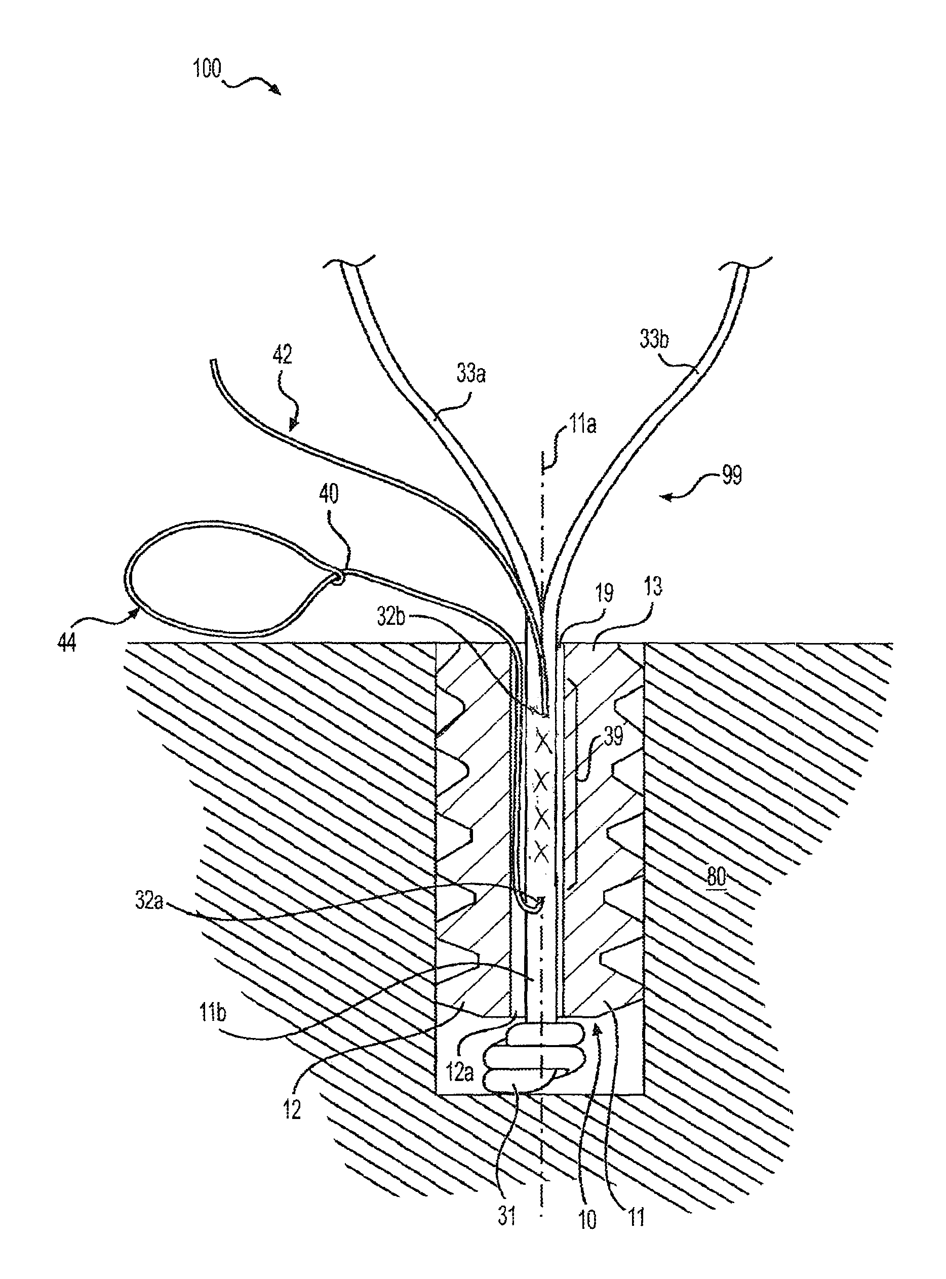
FIG. 1 illustrates a tensionable knotless construct according to an exemplary embodiment.
FIGS. 2 and 3 illustrate an exemplary method of tissue repair with the tensionable knotless construct of FIG. 1.
FIGS. 4 and 5 illustrate another exemplary method of tissue repair with the tensionable knotless construct of FIG. 1.
DETAILED DESCRIPTION
Surgical constructs, systems, and techniques for knotless soft tissue repair and fixation, such as fixation of soft tissue (ligament, tendon, graft, etc.) to bone are disclosed.
The surgical constructs comprise tensionable knotless anchors that are inserted into bone and are provided with a multi-limb suture locking mechanism through single splice (tensionable construct). The tensionable knotless anchor may be formed essentially of suture or suture-like material (i.e., a soft anchor without a solid body) or may be attached to a fixation device.
The multi-limb suture locking mechanism through single splice is formed of a flexible strand (a suture) and a shuttle/pull device (a suture passing instrument) attached to the flexible strand. A flexible strand includes an unsplit region or end (a single main limb of suture or main strand) and a plurality of limbs attached to the unsplit region (main strand). A shuttle/pull device attached to the unsplit region allows passing of the plurality of limbs through the tissue and then spliced back through the unsplit region. In this manner, multiple locking limbs with variable loop lengths are locked through just one splice. If a fixation device (such as a solid anchor, for example) is employed, a splice may be formed outside the body of the fixation device or inside the body of the fixation device. A multi-limb suture locking mechanism through single splice may be employed for tissue repairs.
In an embodiment, a flexible strand (for example, suture) is split into multiple strands or limbs. The strands are passed through the tissue and then spliced back through the single main limb of suture. The individual limbs can slide with variable tension and all could lock within the jacket.
In an embodiment, a surgical construct includes an anchor, a suture that is fixed to the anchor and that splits into two or more limbs, and a suture shuttle with a looped end. A suture can be fixed within the anchor by a knot at the end of the suture. A suture shuttle is inserted into a center of the single suture, and is designed to help shuttle the suture limbs back through the suture, creating a single locking splice. A locking splice may be formed outside an anchor body or inside an anchor body.
In another embodiment, a surgical construct comprises (i) a suture or suture-like material that has at least two regions: a first region or unsplit region; and a second region or split region that splits into two or more limbs; and (ii) a suture shuttle with a looped end. A suture shuttle can be pre-assembled to the first region of the suture or suture-like material. A suture shuttle may be inserted into a center of the first region (unsplit region) of the suture or suture-like material. A suture shuttle shuttles the suture limbs back through the suture or suture-like material, creating a single locking splice in the first region (unsplit region) and a plurality of multiple adjustable closed loops. Multiple adjustable closed loops may have adjustable perimeters, and the perimeters may be all similar or different, or at least one perimeter of one loop different than a perimeter of another loop. A surgical construct may consist essentially of (i) a suture or suture-like material that has at least two regions: a first region or unsplit region; and a second region or split region that splits into two or more limbs; and (ii) a suture shuttle with a looped end.
In another embodiment, a surgical construct includes (i) an anchor; (ii) a suture that is fixed to the anchor and that has at least two regions: a first region or unsplit region; and a second region or split region that splits into two or more limbs; and (iii) a suture shuttle with a looped end. A suture can be fixed within the anchor by a knot at the end of the suture. A suture shuttle can be pre-assembled to the first region of the suture. A suture shuttle may be inserted into a center of the first region (unsplit region) of the suture. A suture shuttle shuttles the suture limbs back through the suture, creating a single locking splice in the first region (unsplit region).
In an embodiment, a surgical system for tissue repairs includes a fixation device comprising a body, a longitudinal axis, a proximal end, and a distal end; and a tensionable construct pre-loaded on the fixation device. A tensionable construct may include a flexible strand with a plurality of limbs, and a shuttling device attached to the flexible strand. A flexible strand may have one end which terminates in a knot, and another end which is split into multiple flexible limbs.
Methods of soft tissue repair which do not require tying of knots and allow adjustment of both the tension of the suture and the location of the tissue with respect to the bone are also disclosed. An exemplary method of tissue repair comprises (i) installing a fixation device in bone, the fixation device comprising a body, a flexible strand split into a plurality of multiple flexible limbs, the flexible strand extending through at least a portion of the body of the fixation device, and a passing device attached to the flexible strand; and (ii) forming, with the multiple flexible limbs of the flexible strand and with the passing device, multiple knotless closed loops having adjustable perimeters, after the step of installing the fixation device in bone.
In one embodiment, two or more suture limbs extending from the split suture are passed through soft tissue. The limbs are then inserted into the suture shuttle loop. The tail of the suture shuttle is pulled, advancing the shuttle loop and two or more suture limbs through the locking splice. The ends of each of the two or more suture limbs are then independently advanced until the desired tension is achieved, creating simple stitches along the soft tissue.
In another embodiment, two or more suture limbs, as well as the suture shuttle loop and tail, are all passed through soft tissue. The limbs are then inserted into the suture shuttle loop. The suture shuttle loop and the two or more suture limbs loaded onto it are advanced through the locking splice by pulling the suture shuttle tail. The two or more suture limbs are then independently advanced until the desired tension is achieved, creating a mattress stitch on the soft tissue.
Another exemplary method of soft tissue repair comprises inter alia: (i) inserting a fixation device of a surgical construct into bone, the surgical construct comprising a fixation device (for example, an anchor) with a flexible strand (for example, suture) that is attached to the fixation device and that is split into multiple strands/limbs, and with a shuttle/pull device (a suture passing instrument) attached to the flexible strand; (ii) passing the multiple strands/limbs around or through tissue to be fixated (or reattached) to bone, and then through an eyelet/loop of the shuttle/pull device; and (iii) subsequently, pulling on the shuttle/pull device to allow the multiple strands/limbs to pass through the flexible strand and to form a locking splice. In an embodiment, individual multiple strands/limbs are each advanced until desired tension is achieved creating simple stitches along the tissue. In an embodiment, individual multiple strands/limbs may be sequentially advanced through the flexible strand.
According to another embodiment, a method of soft tissue repair comprises inter alia: (i) inserting a fixation device of a surgical construct into bone, the surgical construct comprising a fixation device (for example, an anchor) with a flexible strand (for example, suture) that is attached to the fixation device and that is split into multiple strands/limbs, and with a shuttle/pull device (a suture passing instrument) attached to the flexible strand; (ii) passing the multiple strands/limbs together with the shuttle/pull device around or through tissue to be fixated (or reattached) to bone; (iii) subsequently, passing the multiple strands/limbs through an eyelet/loop of the shuttle/pull device; and (iv) subsequently, pulling on the shuttle/pull device to allow the multiple strands/limbs to pass through the flexible strand and to form a locking splice. In an embodiment, individual multiple strands/limbs are each advanced until the desired tension is achieved creating a mattress stitch on the tissue. In an embodiment, individual multiple strands/limbs may be sequentially advanced through the flexible strand.
Referring now to the drawings, where like elements are designated by like reference numerals, FIGS. 1-5 illustrate device 100 (surgical construct, integrated system, surgical system, or assembly 100) which includes fixation device 10 assembled with construct 99 (tensionable construct 99) formed of flexible strand or flexible material 30 and shuttle/pull device 40 (suture passing instrument 40) attached to the flexible strand 30. Tensionable construct 99 may be pre-loaded on the fixation device 10. Although the embodiments below will be described with reference to construct 99 (tensionable construct 99) attached to at least a part of fixation device 10, the disclosure is not limited to these exemplary embodiments and contemplates embodiments wherein construct 99 (tensionable construct 99) acts as a soft anchor, i.e., without being attached to any fixation device such as fixation device 10.
In an exemplary embodiment, fixation device 10 is a tensionable knotless anchor having a solid anchor body 11 provided with a longitudinal axis 11a, a proximal end 13, a distal end 12, and a plurality of ribs or ridges 15 extending circumferentially around body 11. Cannulation 11b extends along the body 11 to allow passage of flexible strand 30 and of a suture passing device, as detailed below. Proximal end 13 of the anchor 10 may contain a socket 19 (FIG. 1) configured to securely engage a tip of a driver.
In an exemplary embodiment, fixation device 10 is an anchor 10 which may be a screw-in anchor or a push-in style anchor. Anchor 10 may be formed of metal, biocompatible plastic such as PEEK, or a bioabsorbable PLLA material. Socket 19 at the distal end 13 of the anchor 10 may have any shape adapted to receive a driver tip for pushing tap-in or screw-in style anchors. Anchor 10 may be made of one or more pieces (a multi-piece construct), or may be provided as an integrated device (a unitary device). Anchor 10 may have various sizes (various diameters and/or lengths) and may be formed of biocompatible materials such as PEEK, biocomposite materials, metals and/or metal alloys, or combination of such materials, among others.
In an embodiment, construct 99 (tensionable construct 99) may be formed of flexible strand 30 (flexible material, suture, or tie down suture 30) and shuttle/pull device 40 (suture passing instrument such as FiberLink.TM. 40, wire loop 40, or nitinol loop 40) attached to the flexible strand 30. In an exemplary embodiment, the flexible strand 30 is a suture strand 30 and the shuttle/pull device 40 is a suture passing device 40. The flexible strand 30 includes an end 32 (unsplit end, unsplit region, or unsplit suture 32) which terminates in knot 31, and another end which is split into multiple limbs 33a, 33b . . . 33n (where "n" may be any number greater than 2). For simplicity, FIGS. 1-5 illustrate flexible strand 30 split into two limbs 33a, 33b; however, the constructs detailed below encompass any number of multiple limbs (suture limbs). Knot 31 may be a static knot 31 which prevents suture 30 from passing through distal blind hole 12a.
Suture 30, which is typically braided or multi-filament or tape, may be preloaded onto the anchor by tying static knot 31 which prevents suture 30 from passing through distal blind hole 12a. The suture may also be preloaded by insert molding or by any other means known in the art. Suture 30 passes through cannulation 11b and terminates in limbs 33a, 33b exiting proximal end 13 of body 11. Tensionable knotless anchor 10 is loaded onto a driver (not shown in FIGS. 1-5), and suture 30 is secured to the driver (for example, wrapped around a cleft of the driver) to fasten tensionable knotless anchor 10 securely to the driver.
Prior to the fastening of the anchor 10 to the driver, suture passing device 40 (for example, a FiberLink.TM., a wire loop, or a nitinol loop) is threaded through suture 30 (i.e., attached to a center of the suture 30 through splice region 39 of unsplit end or region 32), as shown in FIG. 1. Suture passing device 40 includes closed eyelet/loop 44 for passing suture, and tail 42. Suture passing device 40 passes through an aperture 32a of suture 30, within the body of suture 30 and within the tensionable knotless anchor 10, and then exits an aperture 32b of suture 30. A distance between apertures 32a, 32b of suture 30 corresponds to splice or splice region 39. Tensionable knotless anchor 10 loaded with tensionable construct 99 (formed of suture 30 attached to the suture passing device 40) is then secured into bone 80 (for example, into a hole/socket/tunnel formed in bone 80) by using a driver.
FIGS. 2 and 3 depict exemplary repair 200 with tensionable knotless anchor 10 of construct 100 after it has been inserted into a drilled hole in bone 80, the suture released from the driver, and the driver removed. Suture limbs 33a, 33b are passed through (or around) tissue 50 which is to be moved to a desired location (for example, brought into proximity of a drilled hole or socket in bone 80, to be reattached, for example, to bone 80). Suture limbs 33a, 33b are subsequently passed through eyelet/loop 44 of the suture passing device 40. Tail 42 of suture passing device 40 is then pulled, thereby pulling suture limbs 33a, 33b towards tensionable knotless anchor 10, so that each of the suture limbs 33a, 33b is passed/advanced through locking splice 39 (splice region 39) of suture 30, i.e., each of the suture limbs 33a, 33b doubles on itself within suture 30 and inside tensionable knotless anchor 10, to form multiple adjustable tensionable loops 88a, 88b, . . . 88n (where "n" has any value greater than 2). For simplicity, FIGS. 2 and 3 show only two multiple adjustable loops 88a, 88b corresponding to respective multiple limbs 33a, 33b; however, the constructs disclosed herein contemplate any number of multiple adjustable tensionable loops (corresponding to the number of multiple limbs). The suture passing device 40 has also been further pulled through the splice region 39 of suture 30.
FIG. 3 illustrates surgical construct 100 with limbs 33a, 33b after the limbs have been pulled through themselves, creating locking splice 39 and tensionable loops 88a, 88b. The suture passing device (not visible) helps create single locking splice 39 within tensionable knotless anchor 10 by facilitating suture limbs 33a, 33b of suture 30 to pass through (shuttle back through) the unsplit end or unslpit suture 32. Locking splice 39 may be formed within body 11 of fixation device 10, or outside body 11 of fixation device 10. In an embodiment, locking splice 39 may be formed outside body 11 of fixation device 10 and within a bone tunnel formed within bone 80 (wherein construct 100 is inserted).
Once limbs 33a, 33b have been fully passed through suture 30, each of the limbs 33a, 33b may be pulled to reduce the perimeter of loops 88a, 88b and until tissue 50 has been moved to the desired location, such as near a drilled hole in bone 80. Once the desired tension and location is achieved, ends of limbs 33a, 33b may be clipped off to complete the soft tissue repair or fixation 200.
FIGS. 4 and 5 illustrate another exemplary method of soft tissue repair 300 which does not require tying of knots and allows adjustment of both tension of the suture limbs and the location of the tissue with respect to the bone. According to this embodiment, two or more suture limbs 33a, 33b, as well as the suture shuttle loop 44 and tail 42, are all passed through tissue 50. The limbs 33a, 33b are then inserted into the suture shuttle loop 44. The suture shuttle loop 44, together with the two or more suture limbs 33a, 33b loaded onto the suture shuttle loop 44, are advanced through the locking splice 39 by pulling the suture shuttle tail 42, to form adjustable tensionable loops 88a, 88b, as shown in FIG. 5. As in the previously-described embodiment, loops 88a, 88b are multiple adjustable tensionable loops 88a, 88b, each corresponding to a respective one of multiple limbs 33a, 33b. Loops 88a, 88b have an adjustable perimeter and are self-locking, tensionable constructs formed of a splice (spliced region) and a continuous adjustable closed loop attached to the splice. The two or more suture limbs 33a, 33b may be then independently advanced until the desired tension is achieved, creating a mattress stitch on the tissue 50 and completing repair 300. In an embodiment, the two or more suture limbs 33a, 33b may be sequentially or simultaneously advanced, and then independently tensioned so that desired tension is achieved and final repair completed.
Surgical construct 100 with the knotless anchor 10 and tensionable construct 99 may be employed in following exemplary repairs:
1) Used in subscapularis repair for simple partial tears: place anchor 10, pass sutures, shuttle using FiberLoop.RTM. (Arthrex, Inc., Naples, Fla.), and tighten.
2) Full rotator cuff (RC) tears (subscapularis, supraspinatus, infraspinatus). a. Same technique for single row fixation: this will allow for simple repairs passing only one limb of each suture separately through the RC, then shuttle with FiberLink.RTM. (Arthrex, Inc., Naples, Fla.), tighten. b. Single row fixation with horizontal mattress: pass sutures separately, pass FiberLink.RTM. through RC as well, shuttle sutures, tighten. c. Double row fixation with one anchor 10: pass sutures separately, pass FiberLink.RTM. through RC, shuttle sutures, tighten, and bring sutures to lateral row anchor(s). d. Double row fixation with multiple anchors 10: i. Pass sutures/FiberLink.RTM. up through RC either as unit or separately as desired; shuttle sutures into opposing anchor with opposing FiberLink.RTM. for interconnection medially. ii. Since multiple limbs are available, may also shuttle one suture into same anchor for individual anchor fixation. This would be a suture from same anchor/FiberLink.RTM. that was passed through RC separately from FiberLink.RTM.. This allows for SutureBridge.TM. fixation without knots. 1. All passes may be passed through the RC with both anchors done before shuttling sutures. 2. The technique could feature only two sutures per anchor with two anchors medially and two vented SwiveLock.RTM. (Arthrex, Inc., Naples, Fla.) anchors laterally.
3) Partial Articular-sided Supraspinatus Tendon Avulsion (PASTA) Repair: a. Pass anchor 10 through slit in RC or create a sheath to come through the RC easily, then fixate anchor into bone through tendon b. Pass sutures separately via Lasso or BirdBeak.RTM. (Arthrex, Inc., Naples, Fla.) c. Shuttle sutures back into FiberLink.RTM., or if hole too big, shuttle FiberLink.RTM. through RC as well into a different, smaller hole d. Tighten
4) A tape such as FiberTape.RTM. could be incorporated into anchor 10: a. This would allow for SpeedBridge.TM. plus repairs as above to get better fixation and take away that doctors want to "tie" sutures medially to "help with fixation." By interconnecting anchors 10 and passing a suture through the medial tissue, fixing it to its same anchor, surgeons get individual anchor fixation and construct fixation together. b. This would also decrease potential for suture cut-through.
5) InternalBrace.TM.--preferably employed with tape. InternalBrace.TM. may be employed with anchor 10 and interlock anchors across a joint. This would allow a surgeon to "dial in" how much tension to place on the construct. Instead of trying to fix the tension with the initial fixation with the proper length of the FiberTape.RTM. (Arthrex, Inc., Naples, Fla.), this technique would allow a surgeon to tighten sequentially. Any external ligament reconstruction or repair like medial collateral ligament (MCL), medial patella-femoral ligament (MPFL), lateral collateral ligament (LCL), anterior cruciate (AC), ankle, etc. would be appropriate. Any internal reconstruction or repair like anterior cruciate ligament (ACL) or posterior cruciate ligament (PCL) could potentially be internally braced with this anchor as well.
6) Any use of a SwiveLock.RTM. would be appropriate usage of anchor 10 in lieu of a free suture and vented SwiveLock.RTM. (VSL). a. This would include ankle or elbow or hip. b. SCR would be included in this list as a replacement for VSL. c. These could replace the VSL anchors In the SpeedBridge.TM. kit once the tapes were applied.
Although tensionable knotless anchor 10 has been depicted above having ridges 15, and thus designed to be pushed into bone 80, it could instead be fabricated with threads and thereby designed to be twisted or screwed into bone.
Surgical system 100 of FIGS. 1-5 (with knotless tensionable anchor 10, suture 30 with suture limbs 33a, 33b, and suture passing device 40 attached to suture 30) may be employed in exemplary methods of tissue repair such as a Bankart or SLAP repair, wherein the knotless suture anchor 10 (i.e., a modified knotless SutureTak.TM. with suture limbs) simplifies arthroscopic glenohumeral joint instability repair by combining a proven and reproducible suture anchor insertion procedure with knotless soft tissue fixation.
The knotless suture constructs and systems detailed above may be used in conjunction with any knotless fixation devices which can allow a flexible strand and attached suture passing device to form a single locking splice with attached multiple adjustable loops formed by multiple suture limbs. The knotless suture constructs and systems detailed above may be used in conjunction with any additional fixation devices (which may be similar to or different from construct 100) depending on the characteristics of the repair site.
A flexible strand may be a suture strand, a tape such as suture tape, or any suture-like material known in the art that could pass through tissue. A flexible strand may include a high-strength suture, such as an ultrahigh molecular weight polyethylene (UHMWPE) suture. High strength suture may be a FiberWire.RTM. suture (Arthrex). FiberWire.RTM. suture is formed of an advanced, high-strength fiber material, namely ultrahigh molecular weight polyethylene (UHMWPE), sold under the tradenames Spectra.RTM. (Honeywell International Inc., Colonial Heights, Va.) and Dyneema.RTM. (DSM N. V., Heerlen, the Netherlands), braided with at least one other fiber, natural or synthetic, to form lengths of suture material.
A flexible strand may be also formed of TigerWire.RTM. suture, or suture chain (such as FiberChain.RTM. disclosed in U.S. Pat. No. 7,803,173), or suture tape (such as FiberTape.RTM. disclosed in U.S. Pat. No. 7,892,256), the disclosures of which are all incorporated in their entireties herein.
At least one of a flexible strand and a shuttle/pull device may be made of any known suture material, such as UHMWPE material or the FiberWire.RTM. suture. The UHWMPE suture may be without a core to permit ease of splicing. The shuttle/pull device may be a shuttle/pull suture device such as a FiberLink.TM. or a Nitinol loop.
The limbs may also be formed of a flexible material, a stiff material, or combination of stiff and flexible materials, depending on the intended application. Both the limbs and the splice region may be also coated and/or provided in different colors. The knotless anchors of the present invention can be used with any type of flexible material or suture that forms a splice and a loop.
* * * * *
D00000
D00001
D00002
D00003
D00004
D00005
XML
uspto.report is an independent third-party trademark research tool that is not affiliated, endorsed, or sponsored by the United States Patent and Trademark Office (USPTO) or any other governmental organization. The information provided by uspto.report is based on publicly available data at the time of writing and is intended for informational purposes only.
While we strive to provide accurate and up-to-date information, we do not guarantee the accuracy, completeness, reliability, or suitability of the information displayed on this site. The use of this site is at your own risk. Any reliance you place on such information is therefore strictly at your own risk.
All official trademark data, including owner information, should be verified by visiting the official USPTO website at www.uspto.gov. This site is not intended to replace professional legal advice and should not be used as a substitute for consulting with a legal professional who is knowledgeable about trademark law.