Firearm handguard
Kincel , et al.
U.S. patent number 10,260,838 [Application Number 15/299,391] was granted by the patent office on 2019-04-16 for firearm handguard. This patent grant is currently assigned to Bravo Company MFG, Inc.. The grantee listed for this patent is Bravo Company MFG, Inc.. Invention is credited to Eric Stephen Kincel, Jeffrey James O'Brien.


View All Diagrams
| United States Patent | 10,260,838 |
| Kincel , et al. | April 16, 2019 |
Firearm handguard
Abstract
A firearm handguard is disclosed. The handguard comprises a first side section, a second side section coupled to the first side section by a plurality of interlocking fingers, and a bottom section coupled to the first side section and the second side section. The first side section and the second side section each contain at least one accessory mounting aperture. The first side section and the second side section are comprised of a polymer material having molded therein a reinforcement liner including at least one reinforcement aperture. The at least one accessory mounting aperture is aligned with the at least one reinforcement aperture.
| Inventors: | Kincel; Eric Stephen (Las Vegas, NV), O'Brien; Jeffrey James (Las Vegas, NV) | ||||||||||
|---|---|---|---|---|---|---|---|---|---|---|---|
| Applicant: |
|
||||||||||
| Assignee: | Bravo Company MFG, Inc.
(Hartland, WI) |
||||||||||
| Family ID: | 66098548 | ||||||||||
| Appl. No.: | 15/299,391 | ||||||||||
| Filed: | October 20, 2016 |
| Current U.S. Class: | 1/1 |
| Current CPC Class: | F41G 11/003 (20130101); F41C 23/18 (20130101); F41C 23/16 (20130101) |
| Current International Class: | F41A 17/00 (20060101); F41C 23/16 (20060101); F41G 11/00 (20060101); F41C 23/18 (20060101) |
| Field of Search: | ;42/71.01 |
References Cited [Referenced By]
U.S. Patent Documents
| 2078010 | April 1937 | Meepos |
| 2102964 | December 1937 | Mosseberg |
| 3066375 | December 1962 | Knowles et al. |
| 3177587 | April 1965 | Hart |
| 3512653 | May 1970 | Erismann |
| 3559940 | February 1971 | Kruzell |
| 3798818 | March 1974 | Casull |
| 3844627 | October 1974 | Gutner |
| 3861070 | January 1975 | Wild et al. |
| 4167884 | September 1979 | Santanna |
| 4663875 | May 1987 | Tatro |
| 4905396 | March 1990 | Bechtel |
| 4959908 | October 1990 | Weyrauch |
| 5078215 | January 1992 | Nau |
| 5590484 | January 1997 | Mooney et al. |
| 5603594 | February 1997 | Lincoln |
| 5632108 | May 1997 | Ruger et al. |
| 6609321 | August 2003 | Faifer |
| 6836990 | January 2005 | Shiloni |
| 6874269 | April 2005 | Chen et al. |
| 7216451 | May 2007 | Troy |
| 7325352 | February 2008 | Matthews et al. |
| 7430829 | October 2008 | Murello |
| 7464495 | December 2008 | Cahill |
| D613811 | April 2010 | Swan |
| 7712242 | May 2010 | Matthews et al. |
| 7716865 | May 2010 | Daniel et al. |
| 7770317 | August 2010 | Tankersley |
| 7793452 | September 2010 | Samson et al. |
| D636453 | April 2011 | Fitzpatrick et al. |
| D641450 | July 2011 | Ding |
| 7971384 | July 2011 | Lippard |
| 8006430 | August 2011 | Wang |
| 8051595 | November 2011 | Hochstrate et al. |
| 8141289 | March 2012 | Gomez et al. |
| 8201353 | June 2012 | Swan |
| 8245428 | August 2012 | Griffin |
| 8312668 | November 2012 | Kincel |
| 8438770 | May 2013 | Troy |
| 8490316 | July 2013 | Kincel et al. |
| 8539708 | September 2013 | Kenney et al. |
| 8578647 | November 2013 | Storch et al. |
| 8607490 | December 2013 | Zinsner |
| D703286 | April 2014 | Chen et al. |
| 8739448 | June 2014 | Kimmel et al. |
| 8752320 | June 2014 | Masters |
| D710964 | August 2014 | Chvala |
| 8819980 | September 2014 | Geissele |
| D717907 | November 2014 | Montes |
| D717908 | November 2014 | Montes |
| D720421 | December 2014 | Chen |
| 8904691 | December 2014 | Kincel |
| D721407 | January 2015 | Chu |
| 8925236 | January 2015 | Mayberry et al. |
| D722356 | February 2015 | Keller et al. |
| D725723 | March 2015 | Eddie |
| 9103625 | August 2015 | Masters |
| 9157697 | October 2015 | Leclair |
| D744054 | November 2015 | Peterson et al. |
| D746399 | December 2015 | Folkestad, II et al. |
| D746936 | January 2016 | Huang |
| 9239209 | January 2016 | Mayberry et al. |
| 9239210 | January 2016 | Mayberry et al. |
| D749181 | February 2016 | Hu |
| 9297599 | March 2016 | Underwood et al. |
| 9303949 | April 2016 | Oglesby |
| D755338 | May 2016 | Slank |
| D757201 | May 2016 | Meier |
| D757204 | May 2016 | Chow et al. |
| D757878 | May 2016 | Barfoot et al. |
| 9377274 | June 2016 | Kincel |
| 9383163 | July 2016 | Kincel et al. |
| 9389043 | July 2016 | Zhang |
| 9429388 | August 2016 | Mayberry et al. |
| D768800 | October 2016 | Willits |
| 9459078 | October 2016 | Kincel |
| 9464865 | October 2016 | Shea et al. |
| 9470472 | October 2016 | Kincel et al. |
| 9476672 | October 2016 | Wells et al. |
| D771216 | November 2016 | Dubois |
| 9523554 | December 2016 | Mayberry et al. |
| D779013 | February 2017 | Cheng et al. |
| D779014 | February 2017 | Cheng et al. |
| 9581412 | February 2017 | Cheng et al. |
| 9599439 | March 2017 | Sylvester |
| D783760 | April 2017 | Pavlick |
| D783761 | April 2017 | Pavlick |
| D785743 | May 2017 | Pavlick |
| 9696112 | July 2017 | Gottzmann et al. |
| 9709358 | July 2017 | Kincel |
| D795986 | August 2017 | Frederickson et al. |
| 9791239 | October 2017 | Kincel et al. |
| 2001/0045046 | November 2001 | Otteman |
| 2004/0009034 | January 2004 | Miller |
| 2005/0268513 | December 2005 | Battaglia |
| 2006/0191183 | August 2006 | Griffin |
| 2008/0092422 | April 2008 | Daniel et al. |
| 2008/0301994 | December 2008 | Langevin |
| 2009/0000175 | January 2009 | Potterfield et al. |
| 2009/0100734 | April 2009 | Swan et al. |
| 2009/0178325 | July 2009 | Veilleux |
| 2010/0122485 | May 2010 | Kincel |
| 2010/0242332 | September 2010 | Teetzel et al. |
| 2010/0319231 | December 2010 | Stone et al. |
| 2011/0032694 | February 2011 | Swan et al. |
| 2011/0126443 | June 2011 | Sirois |
| 2011/0192066 | August 2011 | Kimmel et al. |
| 2012/0042557 | February 2012 | Gomez et al. |
| 2012/0097807 | April 2012 | Rees |
| 2012/0124880 | May 2012 | Leclair |
| 2012/0167434 | July 2012 | Masters |
| 2012/0180359 | July 2012 | Fitzpatrick et al. |
| 2012/0186123 | July 2012 | Troy et al. |
| 2012/0311908 | December 2012 | Kenney et al. |
| 2013/0031820 | February 2013 | Deros |
| 2013/0036646 | February 2013 | Rubac et al. |
| 2013/0104441 | May 2013 | Kincel |
| 2013/0133238 | May 2013 | Quetschke |
| 2013/0276341 | October 2013 | Wells et al. |
| 2013/0318848 | December 2013 | Kincel |
| 2014/0000142 | January 2014 | Patel |
| 2014/0026459 | January 2014 | Yan et al. |
| 2014/0041273 | February 2014 | Masters |
| 2014/0082990 | March 2014 | Lee |
| 2014/0115938 | May 2014 | Jarboe |
| 2014/0115939 | May 2014 | Troy et al. |
| 2014/0115940 | May 2014 | Bonelli et al. |
| 2014/0130390 | May 2014 | Geissele |
| 2014/0204566 | July 2014 | Kay |
| 2014/0373419 | December 2014 | Leclair |
| 2015/0000171 | January 2015 | Roberts |
| 2015/0198408 | July 2015 | Kincel et al. |
| 2015/0219422 | August 2015 | Kincel |
| 2015/0267993 | September 2015 | Cheng et al. |
| 2015/0285583 | October 2015 | Mayberry et al. |
| 2015/0285584 | October 2015 | Mayberry et al. |
| 2015/0285585 | October 2015 | Hewes et al. |
| 2015/0316347 | November 2015 | Shea et al. |
| 2015/0369555 | December 2015 | Daniel et al. |
| 2015/0369558 | December 2015 | Gottzmann |
| 2016/0010946 | January 2016 | Gibbons et al. |
| 2016/0025120 | January 2016 | Swan et al. |
| 2016/0091277 | March 2016 | Mayberry et al. |
| 2016/0169617 | June 2016 | Daley, Jr. |
| 2016/0187100 | June 2016 | Mayberry et al. |
| 2016/0349011 | December 2016 | Jen |
| 2017/0016695 | January 2017 | Willits |
| 2017/0067718 | March 2017 | Mayberry et al. |
| 2017/0205183 | July 2017 | Ding et al. |
| 2017/0261276 | September 2017 | Morris |
| 2017/0307328 | October 2017 | Shelton et al. |
| 2018/0023919 | January 2018 | Kincel et al. |
| 1832835 | Sep 2007 | EP | |||
| 2013010515 | Jan 2013 | WO | |||
Other References
|
http://b5systems.com/keymod-hand-guard-mid-length/, Dec. 20, 2016, 2 pages. cited by applicant . http://www.recoilweb.com/b5-systems-color-wheels-39707.html, Dec. 20, 2016, 4 pages. cited by applicant . http://www.evike.com/images/large/HG_MP_PTSMOE2.jpg, Dec. 20, 2016, 1 page. cited by applicant . http://ww.evike.com/products/30805/, Dec. 20, 2016, 3 pages. cited by applicant . Co-pending U.S. Appl. No. 15/885,071, filed Jan. 21, 2018. cited by applicant . Co-pending U.S. Appl. No. 29/581,693, filed Oct. 20, 2016. cited by applicant . Co-pending U.S. Appl. No. 15/788,720, filed Oct. 19, 2017. cited by applicant. |
Primary Examiner: Eldred; J. Woodrow
Attorney, Agent or Firm: Michael Best & Friedrich LLP
Claims
What is claimed is:
1. A firearm handguard, the handguard comprising: a first side section; a second side section coupled to the first side section by a plurality of interlocking fingers; and a bottom section coupled to the first side section and the second side section, wherein: the first side section and the second side section each contain at least one accessory mounting aperture, and the first side section and the second side section are comprised of a polymer material, the polymer material having molded therein a reinforcement liner including at least one reinforcement aperture, and wherein the at least one accessory mounting aperture is aligned with the at least one reinforcement aperture.
2. The firearm handguard of claim 1, wherein the reinforcement liner is comprised of metal.
3. The firearm handguard of claim 2, wherein the metal is stainless steel.
4. The firearm handguard of claim 1, wherein the at least one accessory mounting aperture is a KeyMod aperture.
5. The firearm handguard of claim 1, further comprising a round handguard retaining cap.
6. The firearm handguard of claim 1, further comprising a Picatinny rail.
7. The firearm handguard of claim 1, wherein one of the first side section or the second side section additionally comprises at least one ventilation aperture.
8. The firearm handguard of claim 1, further comprising a heat shield coupled to the bottom section.
9. A firearm comprising: an upper receiver; and a handguard coupled to the upper receiver, the handguard comprising: a first side section, a second side section coupled to the first side section by a plurality of interlocking fingers, and a bottom section coupled to the first side section and the second side section, and wherein: the first side section and the second side section each contain at least one accessory mounting aperture, and the first side section and the second side section are comprised of a polymer material, the polymer material having molded therein a reinforcement liner including at least one reinforcement aperture, and wherein the at least one accessory mounting aperture is aligned with the at least one reinforcement aperture.
10. The firearm of claim 9, wherein the reinforcement liner is comprised of metal.
11. The firearm claim 10, wherein the metal is stainless steel.
12. The firearm of claim 9, wherein the at least one accessory mounting aperture is a KeyMod aperture.
13. The firearm of claim 9, wherein the firearm is an AR-10 with a carbine-length gas system.
14. The firearm of claim 9, wherein the firearm is an AR-15 with a mid-length gas system.
15. The firearm of claim 9, wherein the handguard further comprises a round handguard retaining cap.
16. The firearm of claim 9, wherein the handguard further comprises a Picatinny rail.
17. The firearm of claim 9, wherein one of the first side section or the second side section of the handguard additionally comprises at least one ventilation aperture.
18. The firearm of claim 9, wherein the handguard further comprises a heat shield coupled to the bottom section.
19. A firearm handguard, the handguard comprising: a plurality of molded polymer sections; wherein a first section includes a reinforcement liner molded into the polymer and an accessory mounting aperture; wherein at least a portion of the reinforcement liner is not covered by the polymer and is exposed.
20. The firearm handguard of claim 19, wherein the reinforcement liner includes an aperture in the reinforcement liner aligned with the accessory mounting aperture.
21. The firearm handguard of claim 1, wherein at least a portion of the reinforcement liner is not covered by the polymer material and is exposed.
22. The firearm of claim 9, wherein at least a portion of the reinforcement liner is not covered by the polymer material and is exposed.
Description
TECHNICAL FIELD
The present invention generally concerns firearm equipment. More particularly, the present invention relates to a firearm handguard.
BACKGROUND OF THE INVENTION
The two-piece, non-aluminum handguard design was first prototyped for early AR-10s, after which the first AR-15 designs utilized a two-piece handguard system made of Bakelite-type material (early synthetic plastics). These two-piece handguard systems utilized two side halves rather than a top-half and bottom-half design. The first two-piece handguards with a top and bottom design was introduced with the CAR-15, also known as the XM-177/GAU-5 series carbine. This design led to the two-piece handguards for the M16A2 rifle in the 1980s.
Since the introduction of these earlier handguards, a number of manufacturers have developed improved polymer handguards. For example, many modern equivalents of those early handguards offer ergonomics (for the forward gripping hand) and mounting interfaces for firearm accessories. With traditional handguard systems, it was difficult to incorporate both of these advantageous features because the only mounting interface that was available was the Military Standard 1913 Picatinny rail. The Picatinny rail is considered by many to be extremely uncomfortable to handle, unless the railed areas are covered with rail panels. With rail panels installed, however, the overall size of the handguard is too large. To solve this problem, two-piece handguards were developed that utilize a different accessory mounting interfaces. Examples include the KeyMod handguard by B5 and the MOE handguard by Magpul.
Most polymer handguards are injection-molded and manufactured in two pieces, including an upper half and a lower half. Although injection molding is a preferred method of manufacture because it is relatively inexpensive, precise, and versatile, polymer materials are weaker than the traditional aluminum handguard.
The present invention is aimed at one or more of the problems identified above.
BRIEF DESCRIPTION OF THE DRAWINGS
Other advantages of the present invention will be readily appreciated as the same becomes better understood by reference to the following detailed description when considered in connection with the accompanying drawings wherein:
FIG. 1A illustrates a perspective view of an exemplary handguard according to a first embodiment;
FIG. 1B illustrates a top view of the side sections of the handguard of FIG. 1A;
FIG. 1C illustrates an exploded perspective view of the assembled side sections and the bottom section of the handguard of FIG. 1A;
FIG. 1D illustrates a side view of a reinforcement liner for use in the handguard of FIG. 1A;
FIG. 1E illustrates a cutaway view of a side section with reinforcement liner of the handguard of FIG. 1A;
FIG. 1F illustrates a magnified view of an aperture of the handguard of FIG. 1A;
FIG. 1G illustrates a front view of the assembled handguard of FIG. 1A;
FIG. 2 illustrates a perspective view of the handguard of FIG. 1A on a cutaway view of an exemplary firearm;
FIG. 3A illustrates a perspective view of an exemplary handguard according to a second embodiment;
FIG. 3B illustrates a top view of the side sections of the handguard of FIG. 3A;
FIG. 3C illustrates an exploded perspective view of the assembled side sections and the bottom section of the handguard of FIG. 3A;
FIG. 3D illustrates a side view of a reinforcement liner for use in the handguard of FIG. 3A;
FIG. 3E illustrates a cutaway view of a side section with reinforcement liner of the handguard of FIG. 3A;
FIG. 3F illustrates a magnified view of an aperture of the handguard of FIG. 3A;
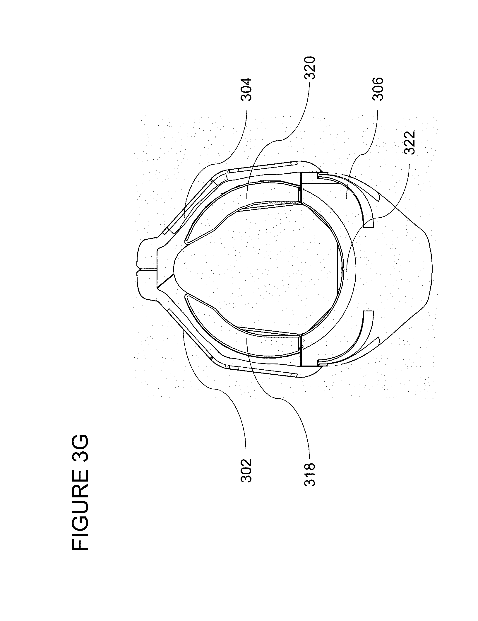
FIG. 3G illustrates a front view of the assembled handguard of FIG. 3A;
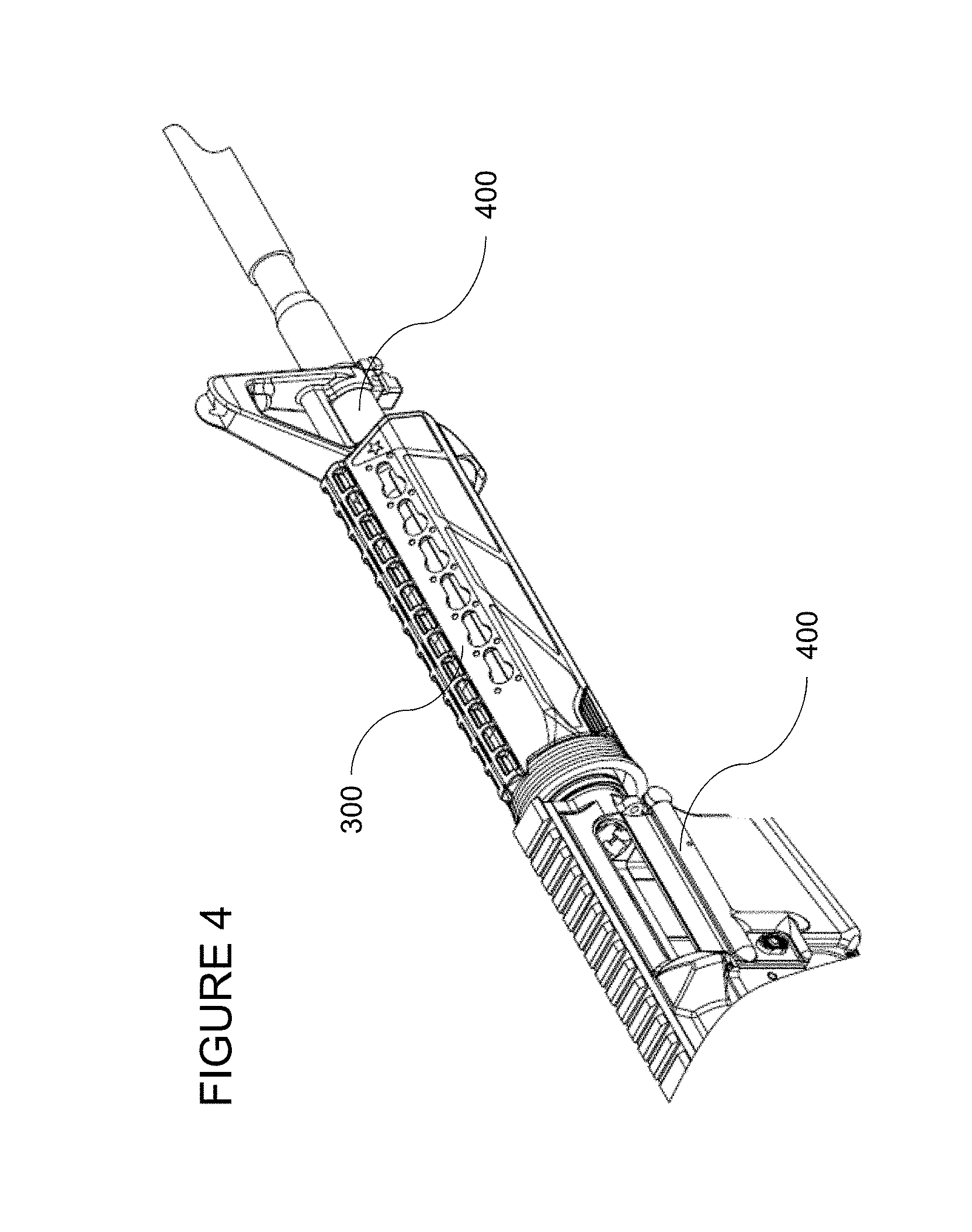
FIG. 4 illustrates a perspective view of the handguard of FIG. 3A on a cutaway view of an exemplary firearm; and
FIG. 5 illustrates front views of inserts for retaining caps for use with the handguard of FIG. 1A.
Corresponding reference characters indicate corresponding parts throughout the drawings.
SUMMARY OF THE INVENTION
In one embodiment of the present invention, a firearm handguard is disclosed. The handguard comprises a first side section, a second side section coupled to the first side section by a plurality of interlocking fingers, and a bottom section coupled to the first side section and the second side section. The first side section and the second side section each contain at least one accessory mounting aperture. The first side section and the second side section are comprised of a polymer material having molded therein a reinforcement liner including at least one reinforcement aperture. The at least one accessory mounting aperture is aligned with the at least one reinforcement aperture.
In an alternate embodiment of the present invention, a firearm is disclosed. The firearm includes an upper receiver and a handguard coupled to the upper receiver. The handguard comprises a first side section, a second side section coupled to the first side section by a plurality of interlocking fingers, and a bottom section coupled to the first side section and the second side section. The first side section and the second side section each contain at least one accessory mounting aperture. The first side section and the second side section are comprised of a polymer material having molded therein a reinforcement liner including at least one reinforcement aperture. The at least one accessory mounting aperture is aligned with the at least one reinforcement aperture.
In yet another embodiment of the present invention, a firearm handguard is disclosed. The firearm handguard includes a plurality of molded polymer sections. A first section of the plurality of molded polymer sections includes a reinforcement liner and an accessory mounting aperture.
DETAILED DESCRIPTION OF THE INVENTION
With reference to the drawings and in operation, the present invention overcomes at least some of the disadvantages of known handguards. The present invention introduces a three-piece, injection-molded handguard design with an added metal reinforcement liner.
Embodiments of the present invention provide a handguard assembly and system and method of mounting the assembly to a firearm. Persons of ordinary skill in the art will realize that the following description of the presently invention is illustrative only and not in any way limiting. Other embodiments of the invention will readily suggest themselves to such skilled persons.
Referring now to FIG. 1A, illustrating a perspective view of an exemplary handguard according to a first embodiment, a handguard 100 is comprised of a first side section 102, a second side section 104, and a bottom section 106.
It is contemplated that any handguard assembly system may be used in connection with the present invention to mount the handguard to the firearm. In a preferred embodiment, the assembly system disclosed in U.S. Pat. No. 8,904,691 entitled "Firearm Handguard Assembly", issued to Eric Kincel on Dec. 9, 2014, and incorporated herein by reference, is used (not shown).
It is also contemplated that the handguard may contain any suitable accessory mounting interface, including, without limitation, a KeyMod interface, a Picatinny rail, an M-LOK interface (by Magpul), a GAMA System interface (by Gibbz Arms), or any combination thereof, though no accessory mounting interface is required for the handguard to function in connection with the present invention. The handguard of the present invention may additionally or alternatively include apertures of any shape or size simply for ventilation. Referring again to FIG. 1A, handguard 100 includes exemplary KeyMod apertures, one of which is labeled 108.
Referring now to FIG. 1B, illustrating a top view of side sections of the handguard of FIG. 1A, first side section 102 and second side section 104 each contains a plurality of interlocking fingers, two of which are labeled 110. Interlocking fingers 110 may be aligned and snapped into place by applying downward force, such that first section 102 and second section 104 are in a locked position. By applying outward pressure to the bottom of each of first side section 102 and second side section 104 and pulling in opposition directions, interlocking fingers 110 may be easily disconnected, placing first side section 102 and second side section 104 into an unlocked position for maintenance or service.
Referring now to FIG. 1C, illustrating a perspective view of the handguard of FIG. 1A, first side section 102 and second side section 104 are shown in an assembled (locked) position. Bottom section 106 includes heat shield 112. First handguard insert 118, second handguard insert 120, and third handguard insert 122 are also shown (described in more detail below with reference to FIG. 1G and FIG. 5).
Reaming now to FIG. 1D, a reinforcement liner for use in the handguard of FIG. 1A is shown. Reinforcement liner 114 is molded into the polymer material of handguard 100, which provides additional strength to the accessory mounting interface (e.g., the KeyMod interface of FIG. 1A) that normal polymer material would not provide on its own. Reinforcement liner 114 may be made of metal, such as stainless steel, aluminum, or titanium. Reinforcement liner 114 may also be made of any other suitably durable material, such as but not limited to fiber reinforced polymers, etc. During the injection molding process, reinforcement liner 114 may be hand-loaded into each of the first side section 102 and second side section 104, which allows for a straight-shot injection molding process. Reinforcement liner 114 may include a plurality of apertures, such as KeyMod apertures, one of which is labeled 116.
Referring now to FIG. 1E, a cutaway view of a side section with reinforcement liner of the handguard of FIG. 1A is shown. Reinforcement liner 114 is molded into second side section 104. Apertures 116 of reinforcement liner 114 align with KeyMod apertures 108. Optionally, reinforcement liner 114 may include additional apertures, other than accessory-mounting apertures, around its perimeter to improve molding (by avoiding delamination) and reduce the weight of reinforcement liner 114.
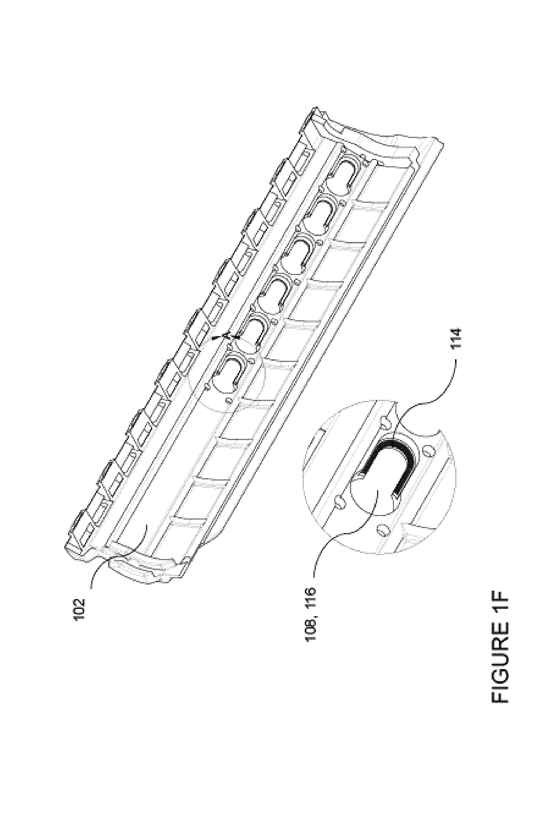
Referring now to FIG. 1F, a magnified view of an aperture of the handguard of FIG. 1A is shown. Reinforcement liner 114 (shaded) is shown in the exposed edges of KeyMod aperture 108, 116. Reinforcement liner 114 is shown in FIG. 1F as partially exposed on the interior of handguard 100 (closest to the barrel). However, it will be understood that reinforcement liner 114 could alternatively be partially exposed on the exterior of handguard 100. In yet another embodiment, no part of reinforcement liner 114 may be exposed.
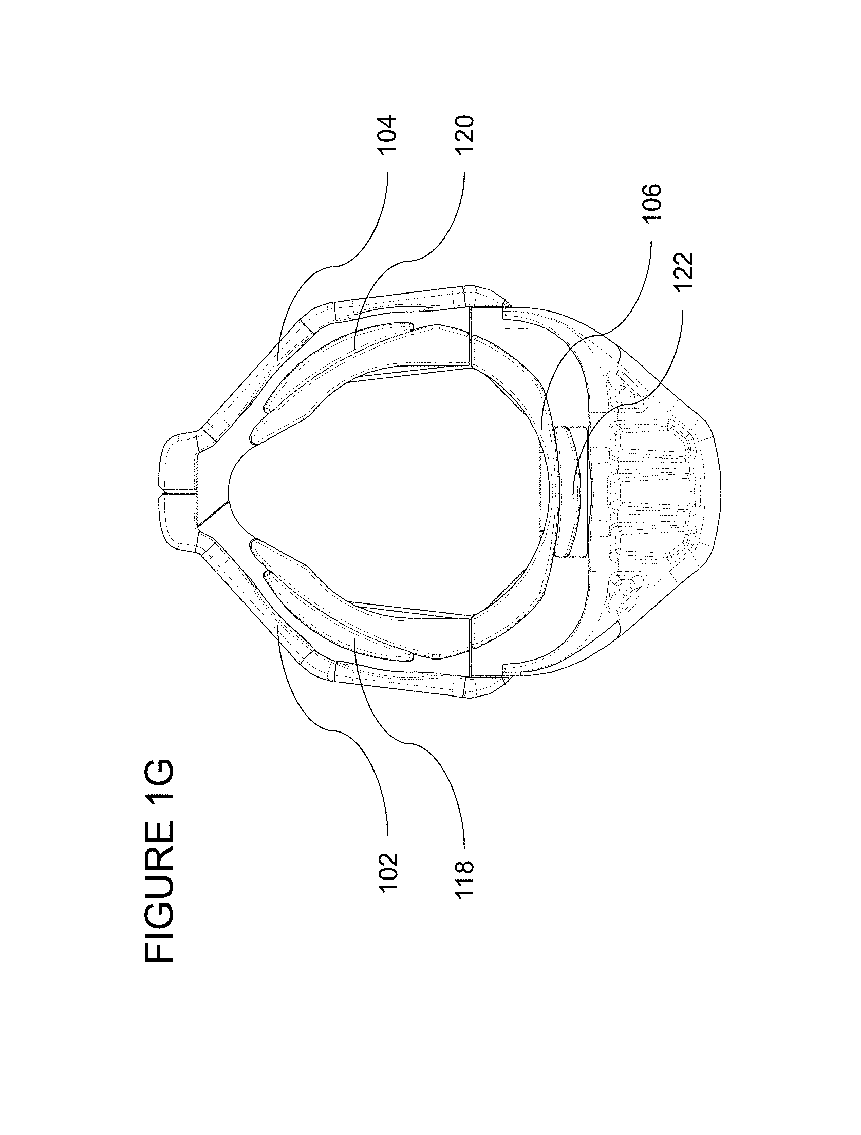
Referring now to FIG. 1G, a front view of the assembled handguard of FIG. 1A is shown. First section 102 and second section 104, in a locked position, may be mounted to bottom section 106 to complete handguard 100. Due to its triangulated structure, when handguard 100 is fully assembled and installed on a firearm (not shown, see FIG. 2), its strength rivals the strength of a one-piece handguard. When in use, first handguard insert 118 may interface with first section 102, second handguard insert 120 may interface with second section 104, and third handguard insert 122 may interface with bottom section 106. First handguard insert 118, second handguard insert 120, and third handguard insert 122 are described in more detail below with reference to FIG. 5.
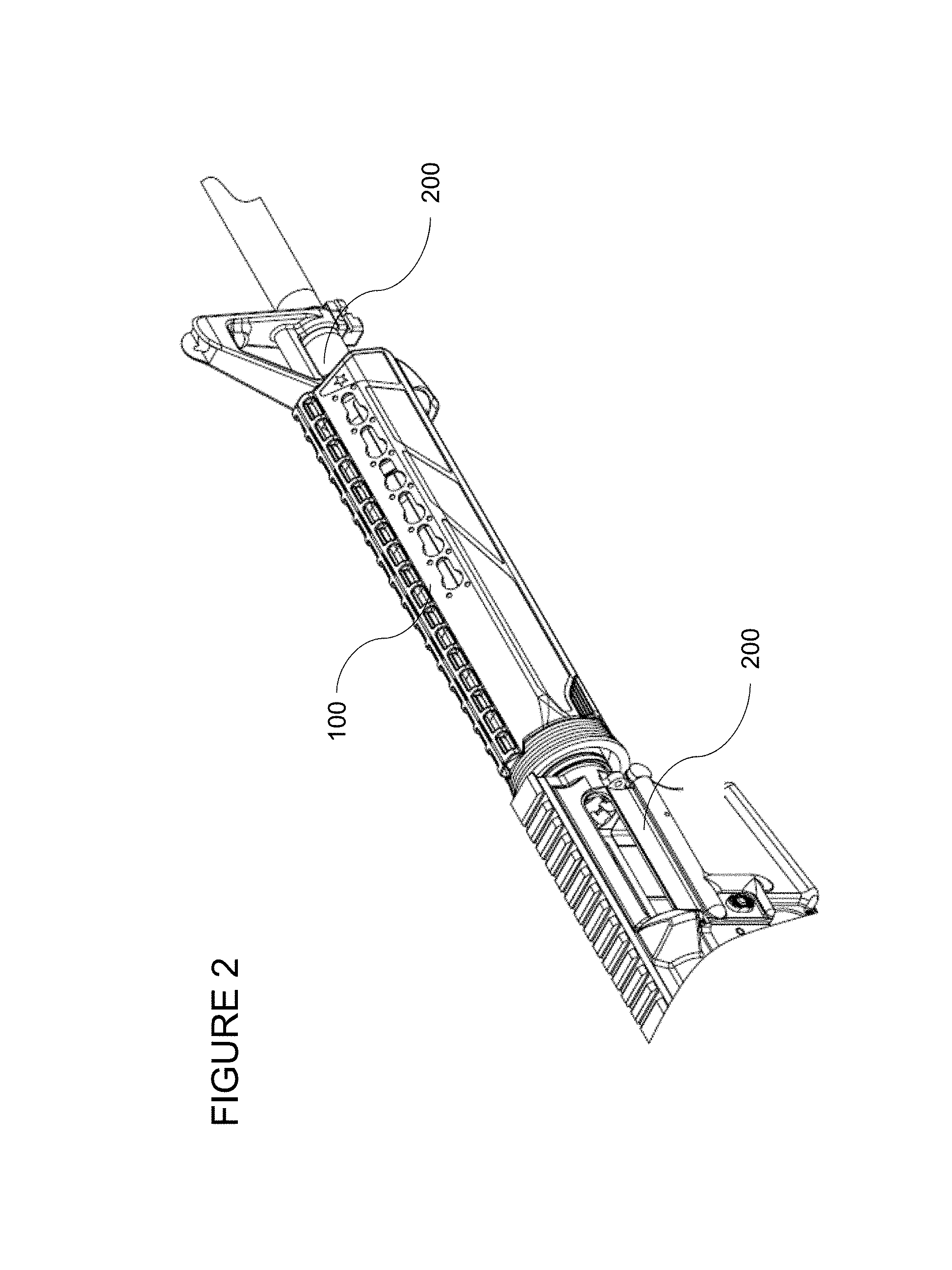
Referring now to FIG. 2, a perspective view of the handguard of FIG. 1A on a cutaway view of an exemplary firearm is illustrated. Handguard 100 is fully assembled and mounted on an exemplary firearm 200. Firearm 200 may be an AR-15 with a mid-length gas system or other firearms.
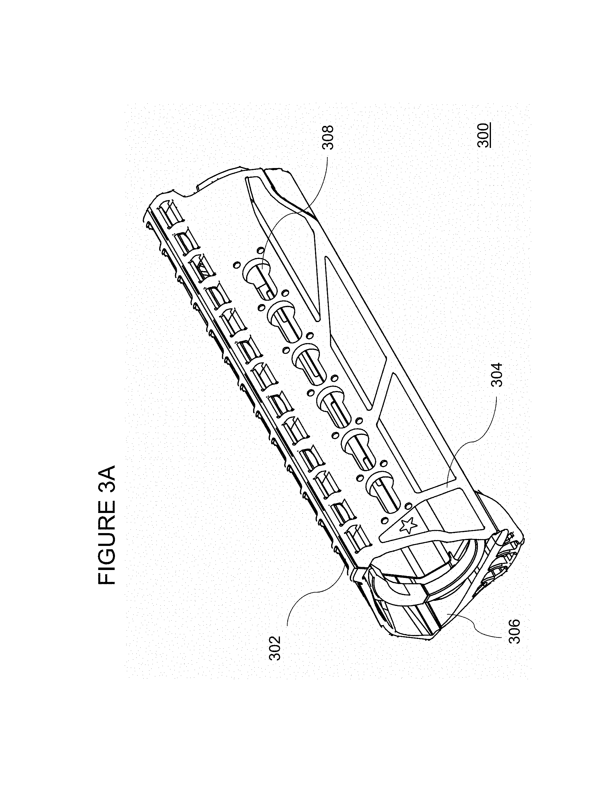
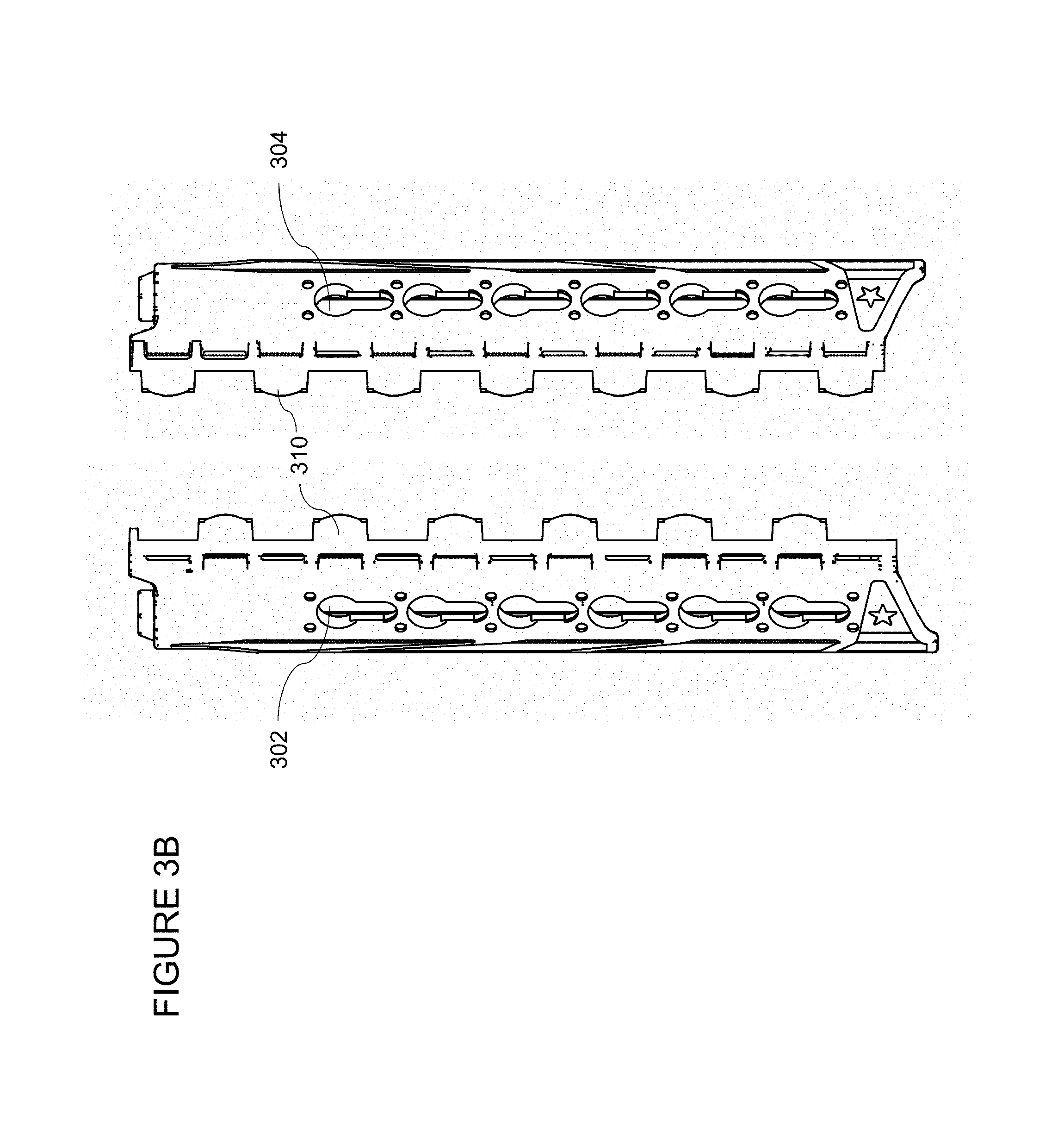
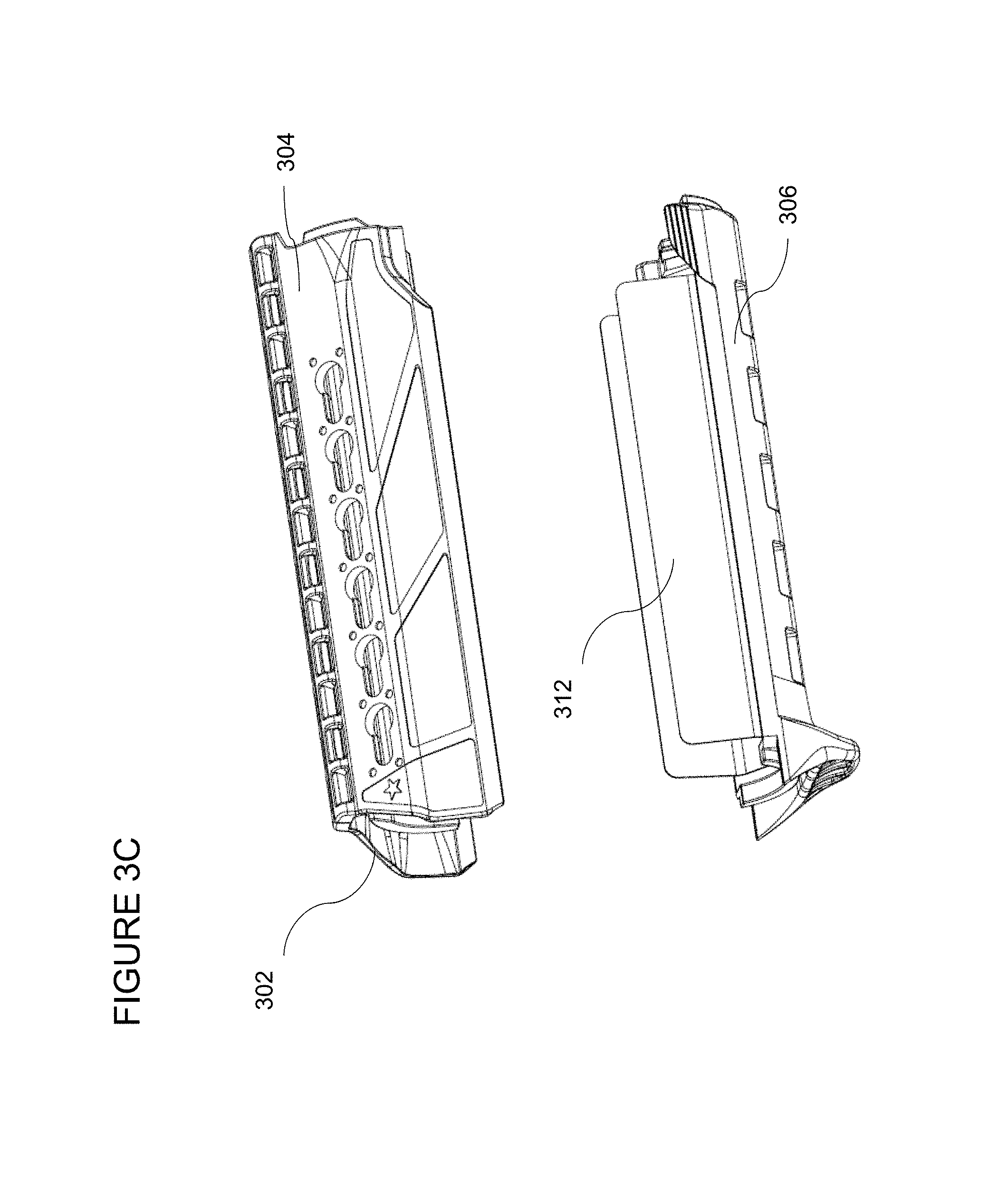
Referring now to FIG. 3A, illustrating a perspective view of an exemplary handguard according to a first embodiment, a handguard 300 is comprised of a first side section 302, a second side section 304, and a bottom section 306.
It is contemplated that the handguard may contain any suitable accessory mounting interface, including, without limitation, a KeyMod interface, a Picatinny rail, an M-LOK interface (by Magpul), a GAMA System interface (by Gibbz Arms), or any combination thereof, though no accessory mounting interface is required for the handguard to function in connection with the present invention. The handguard of the present invention may additionally or alternatively include apertures of any shape or size simply for ventilation. Referring again to FIG. 3A, handguard 300 includes exemplary KeyMod apertures, one of which is labeled 308.
Referring now to FIG. 3B, illustrating a top view of side sections of the handguard of FIG. 3A, first side section 302 and second side section 304 each contains a plurality of interlocking fingers, two of which are labeled 310. Interlocking fingers 310 may be aligned and snapped into place by applying downward force, such that first section 302 and second section 304 are in a locked position. By applying outward pressure to the bottom of each of first side section 302 and second side section 304 and pulling in opposition directions, interlocking fingers 310 may be easily disconnected, placing first side section 302 and second side section 304 into an unlocked position for maintenance or service.
Referring now to FIG. 3C, illustrating a perspective view of the handguard of FIG. 3A, first side section 302 and second side section 304 are shown in an assembled (locked) position. Bottom section 306 includes heat shield 312.
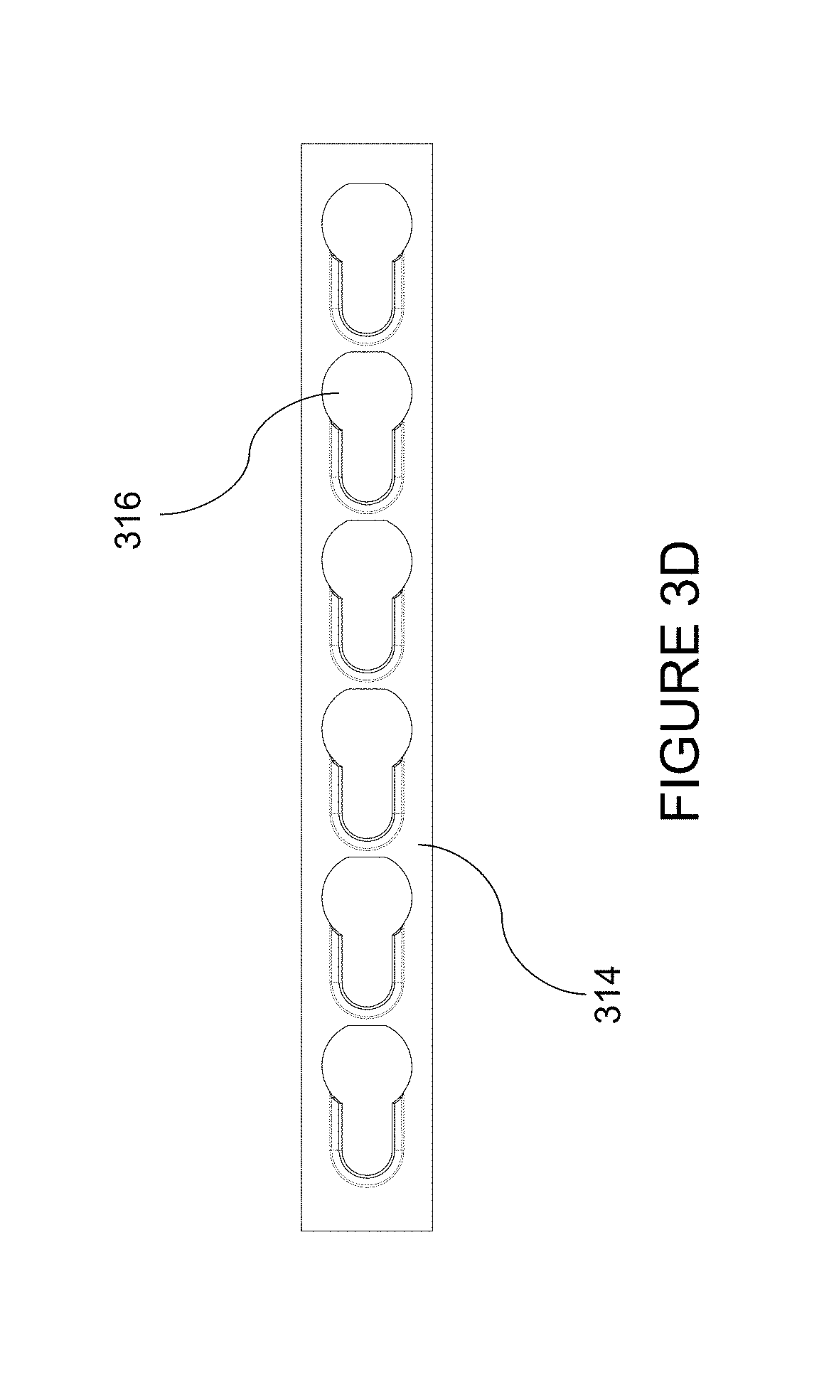
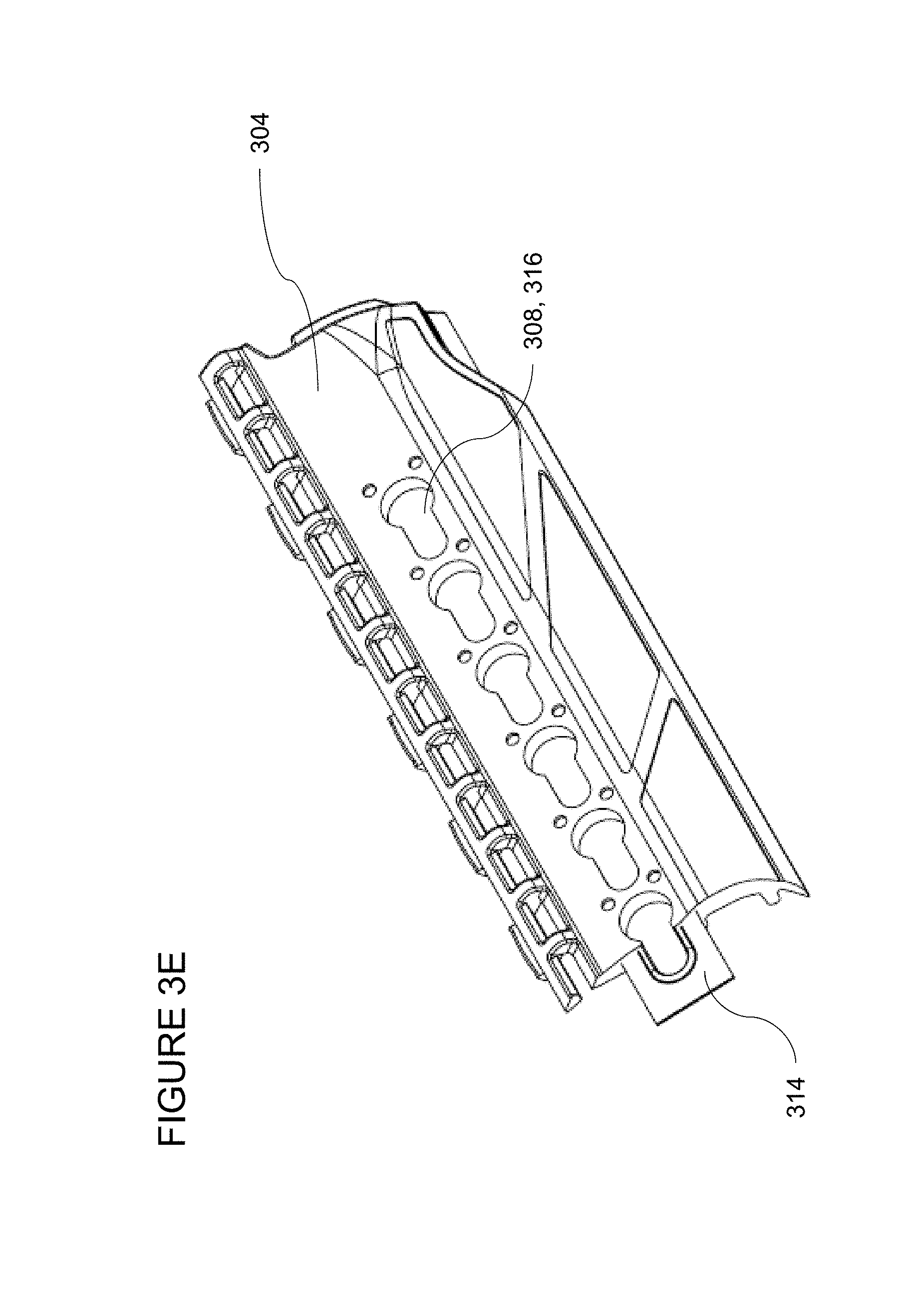
Referring now to FIG. 3D, a reinforcement liner for use in the handguard of FIG. 3A is shown. Reinforcement liner 314 is molded into the polymer material of handguard 300, which provides additional strength to the accessory mounting interface (e.g., the KeyMod interface of FIG. 3A) that normal polymer material would not provide on its own. Reinforcement liner 314 may be made of metal, such as stainless steel, aluminum, or titanium. Reinforcement liner 314 may also be made of any other suitably durable material, such as but not limited to fiber reinforced polymers, etc. During the injection molding process, reinforcement liner 314 may be hand-loaded into each of the first side section 302 and second side section 304, which allows for a straight-shot injection molding process. Reinforcement liner 314 may include a plurality of apertures, such as KeyMod apertures, one of which is labeled 316. Optionally, reinforcement liner 314 may include additional apertures, other than accessory-mounting apertures, around its perimeter to improve molding (by avoiding delamination) and reduce the weight of reinforcement liner 314.
Referring now to FIG. 3E, a cutaway view of a side section with reinforcement liner of the handguard of FIG. 3A is shown. Reinforcement liner 314 is molded into second side section 304. Apertures 316 of reinforcement liner 314 align with KeyMod apertures 308.
Referring now to FIG. 3F, a magnified view of an aperture of the handguard of FIG. 3A is shown. Reinforcement liner 314 (shaded) is shown in the exposed edges of KeyMod aperture 308, 316. Reinforcement liner 314 is shown in FIG. 3F as partially exposed on the interior of handguard 300 (closest to the barrel). However, it will be understood that reinforcement liner 314 could alternatively be partially exposed on the exterior of handguard 300. In yet another embodiment, no part of reinforcement liner 314 may be exposed.
Referring now to FIG. 3G, a front view of the assembled handguard of FIG. 3A is shown. First section 302 and second section 304, in a locked position, may be mounted to bottom section 306 to complete handguard 300. Due to its triangulated structure, when handguard 300 is fully assembled and installed on a firearm (not shown, see FIG. 4), its strength rivals the strength of a one-piece handguard.
Referring now to FIG. 4, a perspective view of the handguard of FIG. 3A on a cutaway view of an exemplary firearm is illustrated. Handguard 300 is fully assembled and mounted on an exemplary firearm 400. Firearm 400 may be an AR-10 with a carbine-length gas system or other firearms.
Referring now to FIG. 5, front views of inserts for retaining caps for use with the handguards of FIG. 1A and FIG. 3A are illustrated. The AR-15 uses two different forward handguard retaining caps, a round retaining cap 500 typically used on shorter (e.g., carbine-length) gas system handguards, such as handguard 300 of FIG. 3A, and a triangular retaining cap 502, typically used on longer (e.g., mid-length) gas system handguards, such as handguard 100 of FIG. 1A. Although round retaining caps are typically used on carbine-length gas systems and triangular retaining caps are traditionally used on mid-length gas systems, some manufacturers use both round retaining caps and triangular retaining caps on handguards for mid-length gas systems. First handguard insert 118, second handguard insert 120, and third handguard insert 122 may be optionally used with the front portion of handguard 100 (mid-length gas system handguard) (see, e.g., FIG. 1C)carbine-length gsh to allow the handguard to interface with round retaining cap 500. When not in use, the handguard will only interface with triangular retaining cap 502, if handguard was originally configured to interface with triangular retaining cap 502.
If needed, the front portion of handguard 300 (carbine-length gas system handguard) may also be made to accept first handguard insert 118, second handguard insert 120, and third handguard insert 122 to adapt to both style of handguard retaining caps 500 and 502.
The above description is illustrative and not restrictive. Many variations of the invention will become apparent to those of skill in the art upon review of this disclosure. While the present invention has been described in connection with a variety of embodiments, these descriptions are not intended to limit the scope of the invention to the particular forms set forth herein. To the contrary, the present descriptions are intended to cover alternatives, modifications, and equivalents as may be included within the spirit and scope of the invention as defined by the appended claim and otherwise appreciated by one of ordinary skill in the art.
* * * * *
References
D00000
D00001
D00002
D00003
D00004
D00005
D00006
D00007
D00008
D00009
D00010
D00011
D00012
D00013
D00014

D00015
D00016
D00017

XML
uspto.report is an independent third-party trademark research tool that is not affiliated, endorsed, or sponsored by the United States Patent and Trademark Office (USPTO) or any other governmental organization. The information provided by uspto.report is based on publicly available data at the time of writing and is intended for informational purposes only.
While we strive to provide accurate and up-to-date information, we do not guarantee the accuracy, completeness, reliability, or suitability of the information displayed on this site. The use of this site is at your own risk. Any reliance you place on such information is therefore strictly at your own risk.
All official trademark data, including owner information, should be verified by visiting the official USPTO website at www.uspto.gov. This site is not intended to replace professional legal advice and should not be used as a substitute for consulting with a legal professional who is knowledgeable about trademark law.