Smart register apparatus and method
Zakaria
U.S. patent number 10,260,765 [Application Number 14/675,285] was granted by the patent office on 2019-04-16 for smart register apparatus and method. This patent grant is currently assigned to Afero, Inc.. The grantee listed for this patent is AFERO, INC.. Invention is credited to Omar Zakaria.


View All Diagrams
| United States Patent | 10,260,765 |
| Zakaria | April 16, 2019 |
Smart register apparatus and method
Abstract
A smart register is described. For example, one embodiment of the smart register apparatus comprises: a set of dampers which enable or restrict airflow from an heating, ventilation, air conditioning (HVAC) system when opened and closed, respectively; a motor to control the opening and closing of the dampers; a battery to provide power to the motor; and register control logic to determine a threshold temperature based on a desired temperature set by a user and to read a current temperature from a temperature sensor, the control logic to automatically open or close the dampers to enable or restrict airflow from the HVAC system based on differences between the threshold temperature and the current temperature.
| Inventors: | Zakaria; Omar (Santa Clara, CA) | ||||||||||
|---|---|---|---|---|---|---|---|---|---|---|---|
| Applicant: |
|
||||||||||
| Assignee: | Afero, Inc. (Los Altos,
CA) |
||||||||||
| Family ID: | 57017497 | ||||||||||
| Appl. No.: | 14/675,285 | ||||||||||
| Filed: | March 31, 2015 |
Prior Publication Data
| Document Identifier | Publication Date | |
|---|---|---|
| US 20160291615 A1 | Oct 6, 2016 | |
| Current U.S. Class: | 1/1 |
| Current CPC Class: | F24F 11/30 (20180101); G05F 1/66 (20130101); F24F 11/0001 (20130101); G05D 23/1934 (20130101); F24F 13/082 (20130101); F24F 2011/0002 (20130101); F24F 2110/10 (20180101) |
| Current International Class: | F24F 11/00 (20180101); G05B 15/02 (20060101); F24F 13/08 (20060101); F24F 11/30 (20180101); G05D 23/19 (20060101); G05F 1/66 (20060101) |
References Cited [Referenced By]
U.S. Patent Documents
| 7168627 | January 2007 | Kates |
| 8020777 | September 2011 | Kates |
| 8249731 | August 2012 | Tran |
| 8550370 | October 2013 | Barrett |
| 9103555 | August 2015 | Zou |
| 9812926 | November 2017 | Rodriguez |
| 2006/0071087 | April 2006 | Kates |
| 2010/0163633 | July 2010 | Barrett |
| 2014/0000861 | January 2014 | Barrett |
| 2014/0312126 | October 2014 | Ramini |
| 2014/0330438 | November 2014 | Haines |
| 2015/0288681 | October 2015 | Park |
| 2016/0182459 | June 2016 | Britt |
| 2016/0259351 | September 2016 | Barrett |
Attorney, Agent or Firm: Nicholson De Vos Webster & Elliott LLP
Claims
What is claimed is:
1. A smart register apparatus comprising: a set of dampers which enable or restrict airflow from a heating, ventilation, or air conditioning (HVAC) system when opened and closed, respectively; a motor to control the opening and closing of the dampers; a battery to provide power to the motor; a wireless communication interface to couple the smart register to an Internet of Things (IoT) hub, the IoT hub to send a desired temperature set by a user to the smart register, the desired temperature set by the user via an app or browser installed on a user device; and register control logic circuitry to determine a threshold temperature based on the desired temperature received from the IOT hub and to read a current temperature from a temperature sensor, the register control logic circuitry to automatically open or close the dampers to enable or restrict airflow from the HVAC system based on differences between the threshold temperature and the current temperature.
2. The smart register apparatus as in claim 1 wherein the threshold temperature comprises an offset from the desired temperature.
3. The smart register apparatus as in claim 1 wherein the battery comprises a rechargeable battery.
4. The smart register apparatus as in claim 3 further comprising a power source to generate power using air flowing through the dampers to charge the battery.
5. The smart register apparatus as in claim 4 wherein the power source comprises a miniature set of wind turbines and an induction generator may be used to convert the kinetic energy of air flowing through the dampers into electrical energy to charge the battery.
6. The smart register apparatus as in claim 3 further comprising a solar power source to generate power electromagnetic radiation to charge the battery.
7. The smart register apparatus as in claim 1 wherein the IoT hub comprises temperature control logic circuitry to receive the current temperature from a temperature sensor and to provide the current temperature to the smart register.
8. The smart register apparatus as in claim 1 wherein the wireless communication interface comprises a Bluetooth Low Energy (BTLE) interface.
9. A system comprising: an Internet of Things (IoT) hub comprising a first wireless interface to receive current temperature data from a set of one or more temperature sensors; one or more smart registers, each comprising a set of dampers which enable or restrict airflow from a heating, ventilation, air conditioning (HVAC) system when opened and closed, respectively; a motor to control the opening and closing of the dampers; a battery to provide power to the motor; and a second wireless interface to establish a communication channel with the IoT hub; and temperature control logic circuitry implemented within the IoT hub to determine a threshold temperature based on a desired temperature set by a user and to send a command to the smart register to cause register control logic circuitry within the smart register to open or close the dampers to enable or restrict airflow from the HVAC system based on differences between the threshold temperature and the current temperature.
10. The system as in claim 9 wherein the threshold temperature comprises an offset from the desired temperature.
11. The system as in claim 9 wherein the battery comprises a rechargeable battery.
12. The system as in claim 11 further comprising a power source to generate power using air flowing through the dampers to charge the battery.
13. The system as in claim 12 wherein the power source comprises a miniature set of wind turbines and an induction generator may be used to convert the kinetic energy of air flowing through the dampers into electrical energy to charge the battery.
14. The system as in claim 11 further comprising a solar power source to generate power electromagnetic radiation to charge the battery.
15. The system as in claim 9 wherein the first and second wireless interfaces comprise Bluetooth Low Energy (BTLE) interfaces.
16. A system as in claim 9 wherein a first smart register is to be used in a first room in a home and a second smart register is to be used in a second room in the home, wherein the temperature control logic circuitry is to send a first command to the first smart register to cause the register control logic circuitry within the first smart register to close its dampers while the HVAC system is running and while the dampers within the second smart register remain open.
17. The system as in claim 16 wherein the temperature control logic circuitry is to send the first command to the first smart register to cause the register control logic circuitry within the first smart register to close its dampers while the HVAC system is running when the current temperature provided by a sensor in the same room as the first smart register is equal to the threshold temperature.
18. The system as in claim 17 wherein the temperature control logic circuitry is to send a second command to the second smart register to cause the register control logic circuitry within the second smart register to close its dampers when the current temperature provided by a sensor in the same room as the second smart register is equal to the threshold temperature.
Description
BACKGROUND
Field of the Invention
This invention relates generally to the field of computer systems. More particularly, the invention relates to a smart register apparatus and method which may be implemented within the context of an Internet of Things system.
Description of the Related Art
1. Internet of Things (IoT)
The "Internet of Things" refers to the interconnection of uniquely-identifiable embedded devices within the Internet infrastructure. Ultimately, IoT is expected to result in new, wide-ranging types of applications in which virtually any type of physical thing may provide information about itself or its surroundings and/or may be controlled remotely via client devices over the Internet.
IoT development and adoption has been slow due to issues related to connectivity, power, and a lack of standardization. For example, one obstacle to IoT development and adoption is that no standard platform exists to allow developers to design and offer new IoT devices and services. In order enter into the IoT market, a developer must design the entire IoT platform from the ground up, including the network protocols and infrastructure, hardware, software and services required to support the desired IoT implementation. As a result, each provider of IoT devices uses proprietary techniques for designing and connecting the IoT devices, making the adoption of multiple types of IoT devices burdensome for end users. Another obstacle to IoT adoption is the difficulty associated with connecting and powering IoT devices. Connecting appliances such as refrigerators, garage door openers, environmental sensors, home security sensors/controllers, etc, for example, requires an electrical source to power each connected IoT device, and such an electrical source is often not conveniently located.
2. Systems for Improving HVAC Efficiency
Current systems for improving the efficiency of HVAC (heating ventilation and air conditioning) are capable of detecting when users are away from home (e.g., using a motion sensor) and, in response, turning off or modifying the desired temperature. These systems are also capable of maintaining a history of temperature settings specified by the end user and responsively determining a temperature schedule based on the recorded history. One example of such a system is the Nest.TM. thermostat which includes a motion sensor to detect periods of time when users are away from the home and which automatically sets a schedule based on a history of user-specified temperature settings.
One problem with current HVAC systems, however, is that in a common household where there are two or more rooms, certain rooms will be more difficult to heat or cool than other rooms. For example, a bedroom which only has one wall exposed to the outside of the home may reach a desired temperature quickly and hold the desired temperature for a longer period of time. By contrast, a bedroom which has three walls exposed to the outside of the home may take longer to heat or cool and may drift from the desired temperature more quickly. Consequently, users will often increase the temperature reading on the thermostat above or below the desired temperature (i.e., over- or under-shooting by a certain amount) so that the room which is harder to heat or cool reaches and maintains the desired temperature, while the other rooms achieve a temperature which is either higher or lower, respectively, than the desired temperature. The end result is a significant amount of wasted energy heating or cooling the home.
BRIEF DESCRIPTION OF THE DRAWINGS
A better understanding of the present invention can be obtained from the following detailed description in conjunction with the following drawings, in which:
FIGS. 1A-B illustrates different embodiments of an IoT system architecture;
FIG. 2 illustrates an IoT device in accordance with one embodiment of the invention;
FIG. 3 illustrates an IoT hub in accordance with one embodiment of the invention;
FIG. 4A-B illustrate embodiments of the invention for controlling and collecting data from IoT devices, and generating notifications;
FIG. 5 illustrates embodiments of the invention for collecting data from IoT devices and generating notifications from an IoT hub and/or IoT service;
FIG. 6 illustrates one embodiment of a smart duct implemented within the context of an Internet of Things (IoT) system;
FIG. 7 illustrates a smart duct in accordance with one embodiment of the invention;
FIG. 8 illustrates a method in accordance with one embodiment of the invention;
FIG. 9 illustrates a method in accordance with another embodiment of the invention;
FIG. 10 illustrates a high level view of one embodiment of a security architecture;
FIG. 11 illustrates one embodiment of an architecture in which a subscriber identity module (SIM) is used to store keys on IoT devices;
FIG. 12A illustrates one embodiment in which IoT devices are registered using barcodes or QR codes;
FIG. 12B illustrates one embodiment in which pairing is performed using barcodes or QR codes;
FIG. 13 illustrates one embodiment of a method for programming a SIM using an IoT hub;
FIG. 14 illustrates one embodiment of a method for registering an IoT device with an IoT hub and IoT service; and
FIG. 15 illustrates one embodiment of a method for encrypting data to be transmitted to an IoT device.
DETAILED DESCRIPTION
In the following description, for the purposes of explanation, numerous specific details are set forth in order to provide a thorough understanding of the embodiments of the invention described below. It will be apparent, however, to one skilled in the art that the embodiments of the invention may be practiced without some of these specific details. In other instances, well-known structures and devices are shown in block diagram form to avoid obscuring the underlying principles of the embodiments of the invention.
One embodiment of the invention comprises an Internet of Things (IoT) platform which may be utilized by developers to design and build new IoT devices and applications. In particular, one embodiment includes a base hardware/software platform for IoT devices including a predefined networking protocol stack and an IoT hub through which the IoT devices are coupled to the Internet. In addition, one embodiment includes an IoT service through which the IoT hubs and connected IoT devices may be accessed and managed as described below. In addition, one embodiment of the IoT platform includes an IoT app or Web application (e.g., executed on a client device) to access and configured the IoT service, hub and connected devices. Existing online retailers and other Website operators may leverage the IoT platform described herein to readily provide unique IoT functionality to existing user bases.
FIG. 1A illustrates an overview of an architectural platform on which embodiments of the invention may be implemented. In particular, the illustrated embodiment includes a plurality of IoT devices 101-105 communicatively coupled over local communication channels 130 to a central IoT hub 110 which is itself communicatively coupled to an IoT service 120 over the Internet 220. Each of the IoT devices 101-105 may initially be paired to the IoT hub 110 (e.g., using the pairing techniques described below) in order to enable each of the local communication channels 130. In one embodiment, the IoT service 120 includes an end user database 122 for maintaining user account information and data collected from each user's IoT devices. For example, if the IoT devices include sensors (e.g., temperature sensors, accelerometers, heat sensors, motion detectore, etc), the database 122 may be continually updated to store the data collected by the IoT devices 101-105. The data stored in the database 122 may then be made accessible to the end user via the IoT app or browser installed on the user's device 135 (or via a desktop or other client computer system) and to web clients (e.g., such as websites 130 subscribing to the IoT service 120).
The IoT devices 101-105 may be equipped with various types of sensors to collect information about themselves and their surroundings and provide the collected information to the IoT service 120, user devices 135 and/or external Websites 130 via the IoT hub 110. Some of the IoT devices 101-105 may perform a specified function in response to control commands sent through the IoT hub 110. Various specific examples of information collected by the IoT devices 101-105 and control commands are provided below. In one embodiment described below, the IoT device 101 is a user input device designed to record user selections and send the user selections to the IoT service 120 and/or Website.
In one embodiment, the IoT hub 110 includes a cellular radio to establish a connection to the Internet 220 via a cellular service 115 such as a 4G (e.g., Mobile WiMAX, LTE) or 5G cellular data service. Alternatively, or in addition, the IoT hub 110 may include a WiFi radio to establish a WiFi connection through a WiFi access point or router 116 which couples the IoT hub 110 to the Internet (e.g., via an Internet Service Provider providing Internet service to the end user). Of course, it should be noted that the underlying principles of the invention are not limited to any particular type of communication channel or protocol.
In one embodiment, the IoT devices 101-105 are ultra low-power devices capable of operating for extended periods of time on battery power (e.g., years). To conserve power, the local communication channels 130 may be implemented using a low-power wireless communication technology such as Bluetooth Low Energy (LE). In this embodiment, each of the IoT devices 101-105 and the IoT hub 110 are equipped with Bluetooth LE radios and protocol stacks.
As mentioned, in one embodiment, the IoT platform includes an IoT app or Web application executed on user devices 135 to allow users to access and configure the connected IoT devices 101-105, IoT hub 110, and/or IoT service 120. In one embodiment, the app or web application may be designed by the operator of a Website 130 to provide IoT functionality to its user base. As illustrated, the Website may maintain a user database 131 containing account records related to each user.
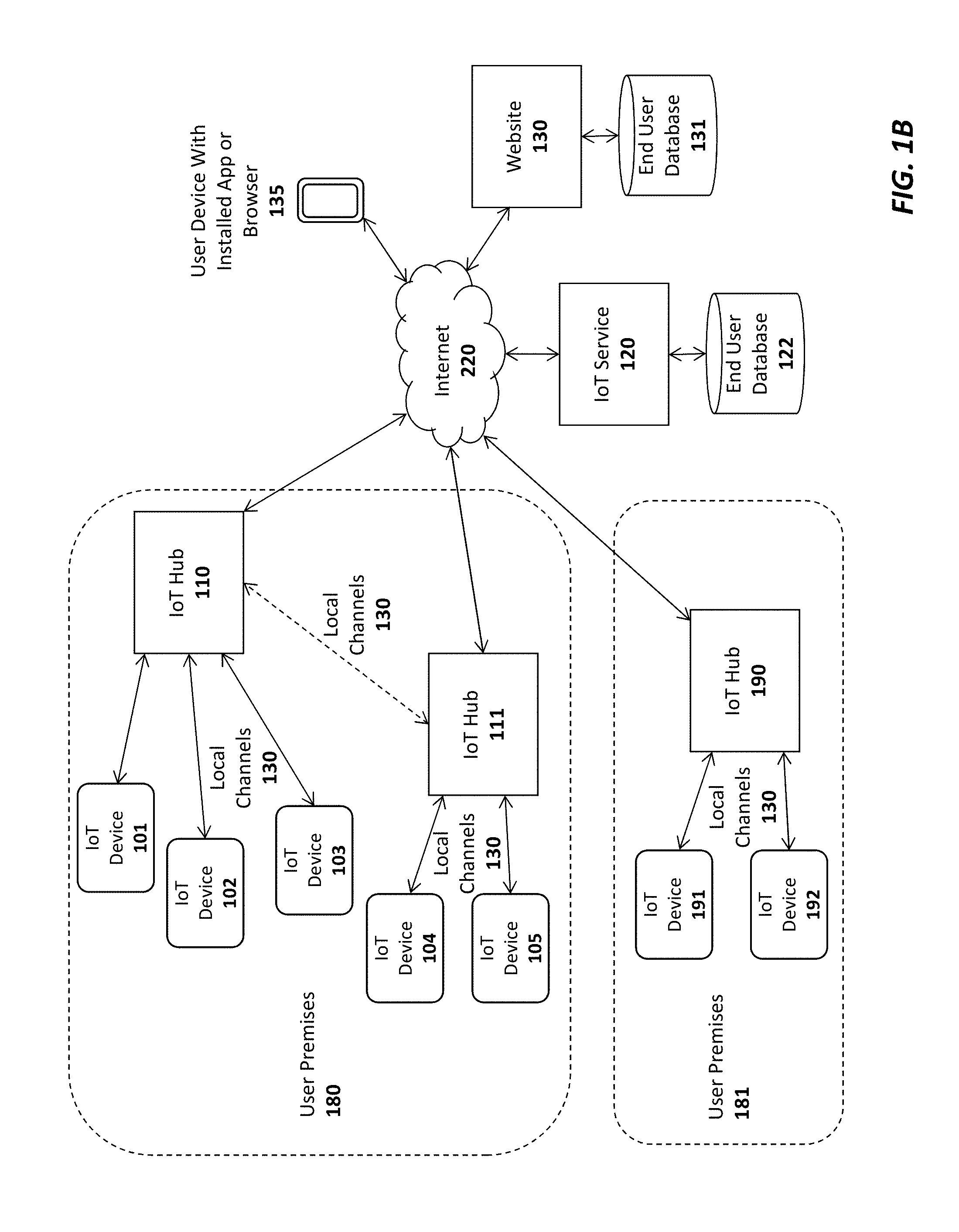
FIG. 1B illustrates additional connection options for a plurality of IoT hubs 110-111, 190 In this embodiment a single user may have multiple hubs 110-111 installed onsite at a single user premises 180 (e.g., the user's home or business). This may be done, for example, to extend the wireless range needed to connect all of the IoT devices 101-105. As indicated, if a user has multiple hubs 110, 111 they may be connected via a local communication channel (e.g., Wifi, Ethernet, Power Line Networking, etc). In one embodiment, each of the hubs 110-111 may establish a direct connection to the IoT service 120 through a cellular 115 or WiFi 116 connection (not explicitly shown in FIG. 1B). Alternatively, or in addition, one of the IoT hubs such as IoT hub 110 may act as a "master" hub which provides connectivity and/or local services to all of the other IoT hubs on the user premises 180, such as IoT hub 111 (as indicated by the dotted line connecting IoT hub 110 and IoT hub 111). For example, the master IoT hub 110 may be the only IoT hub to establish a direct connection to the IoT service 120. In one embodiment, only the "master" IoT hub 110 is equipped with a cellular communication interface to establish the connection to the IoT service 120. As such, all communication between the IoT service 120 and the other IoT hubs 111 will flow through the master IoT hub 110. In this role, the master IoT hub 110 may be provided with additional program code to perform filtering operations on the data exchanged between the other IoT hubs 111 and IoT service 120 (e.g., servicing some data requests locally when possible).
Regardless of how the IoT hubs 110-111 are connected, in one embodiment, the IoT service 120 will logically associate the hubs with the user and combine all of the attached IoT devices 101-105 under a single comprehensive user interface, accessible via a user device with the installed app 135 (and/or a browser-based interface).
In this embodiment, the master IoT hub 110 and one or more slave IoT hubs 111 may connect over a local network which may be a WiFi network 116, an Ethernet network, and/or a using power-line communications (PLC) networking (e.g., where all or portions of the network are run through the user's power lines). In addition, to the IoT hubs 110-111, each of the IoT devices 101-105 may be interconnected with the IoT hubs 110-111 using any type of local network channel such as WiFi, Ethernet, PLC, or Bluetooth LE, to name a few.
FIG. 1B also shows an IoT hub 190 installed at a second user premises 181. A virtually unlimited number of such IoT hubs 190 may be installed and configured to collect data from IoT devices 191-192 at user premises around the world. In one embodiment, the two user premises 180-181 may be configured for the same user. For example, one user premises 180 may be the user's primary home and the other user premises 181 may be the user's vacation home. In such a case, the IoT service 120 will logically associate the IoT hubs 110-111, 190 with the user and combine all of the attached IoT devices 101-105, 191-192 under a single comprehensive user interface, accessible via a user device with the installed app 135 (and/or a browser-based interface).
As illustrated in FIG. 2, an exemplary embodiment of an IoT device 101 includes a memory 210 for storing program code and data 201-203 and a low power microcontroller 200 for executing the program code and processing the data. The memory 210 may be a volatile memory such as dynamic random access memory (DRAM) or may be a non-volatile memory such as Flash memory. In one embodiment, a non-volatile memory may be used for persistent storage and a volatile memory may be used for execution of the program code and data at runtime. Moreover, the memory 210 may be integrated within the low power microcontroller 200 or may be coupled to the low power microcontroller 200 via a bus or communication fabric. The underlying principles of the invention are not limited to any particular implementation of the memory 210.
As illustrated, the program code may include application program code 203 defining an application-specific set of functions to be performed by the IoT device 201 and library code 202 comprising a set of predefined building blocks which may be utilized by the application developer of the IoT device 101. In one embodiment, the library code 202 comprises a set of basic functions required to implement an IoT device such as a communication protocol stack 201 for enabling communication between each IoT device 101 and the IoT hub 110. As mentioned, in one embodiment, the communication protocol stack 201 comprises a Bluetooth LE protocol stack. In this embodiment, Bluetooth LE radio and antenna 207 may be integrated within the low power microcontroller 200. However, the underlying principles of the invention are not limited to any particular communication protocol.
The particular embodiment shown in FIG. 2 also includes a plurality of input devices or sensors 210 to receive user input and provide the user input to the low power microcontroller, which processes the user input in accordance with the application code 203 and library code 202. In one embodiment, each of the input devices include an LED 209 to provide feedback to the end user.
In addition, the illustrated embodiment includes a battery 208 for supplying power to the low power microcontroller. In one embodiment, a non-chargeable coin cell battery is used. However, in an alternate embodiment, an integrated rechargeable battery may be used (e.g., rechargeable by connecting the IoT device to an AC power supply (not shown)).
A speaker 205 is also provided for generating audio. In one embodiment, the low power microcontroller 299 includes audio decoding logic for decoding a compressed audio stream (e.g., such as an MPEG-4/Advanced Audio Coding (AAC) stream) to generate audio on the speaker 205. Alternatively, the low power microcontroller 200 and/or the application code/data 203 may include digitally sampled snippets of audio to provide verbal feedback to the end user as the user enters selections via the input devices 210.
In one embodiment, one or more other/alternate I/O devices or sensors 250 may be included on the IoT device 101 based on the particular application for which the IoT device 101 is designed. For example, an environmental sensor may be included to measure temperature, pressure, humidity, etc. A security sensor and/or door lock opener may be included if the IoT device is used as a security device. Of course, these examples are provided merely for the purposes of illustration. The underlying principles of the invention are not limited to any particular type of IoT device. In fact, given the highly programmable nature of the low power microcontroller 200 equipped with the library code 202, an application developer may readily develop new application code 203 and new I/O devices 250 to interface with the low power microcontroller for virtually any type of IoT application.
In one embodiment, the low power microcontroller 200 also includes a secure key store for storing encryption keys for encrypting communications and/or generating signatures. Alternatively, the keys may be secured in a subscriber identify module (SIM).
A wakeup receiver 207 is included in one embodiment to wake the IoT device from an ultra low power state in which it is consuming virtually no power. In one embodiment, the wakeup receiver 207 is configured to cause the IoT device 101 to exit this low power state in response to a wakeup signal received from a wakeup transmitter 307 configured on the IoT hub 110 as shown in FIG. 3. In particular, in one embodiment, the transmitter 307 and receiver 207 together form an electrical resonant transformer circuit such as a Tesla coil. In operation, energy is transmitted via radio frequency signals from the transmitter 307 to the receiver 207 when the hub 110 needs to wake the IoT device 101 from a very low power state. Because of the energy transfer, the IoT device 101 may be configured to consume virtually no power when it is in its low power state because it does not need to continually "listen" for a signal from the hub (as is the case with network protocols which allow devices to be awakened via a network signal). Rather, the microcontroller 200 of the IoT device 101 may be configured to wake up after being effectively powered down by using the energy electrically transmitted from the transmitter 307 to the receiver 207.
As illustrated in FIG. 3, the IoT hub 110 also includes a memory 317 for storing program code and data 305 and hardware logic 301 such as a microcontroller for executing the program code and processing the data. A wide area network (WAN) interface 302 and antenna 310 couple the IoT hub 110 to the cellular service 115. Alternatively, as mentioned above, the IoT hub 110 may also include a local network interface (not shown) such as a WiFi interface (and WiFi antenna) or Ethernet interface for establishing a local area network communication channel. In one embodiment, the hardware logic 301 also includes a secure key store for storing encryption keys for encrypting communications and generating/verifying signatures. Alternatively, the keys may be secured in a subscriber identify module (SIM).
A local communication interface 303 and antenna 311 establishes local communication channels with each of the IoT devices 101-105. As mentioned above, in one embodiment, the local communication interface 303/antenna 311 implements the Bluetooth LE standard. However, the underlying principles of the invention are not limited to any particular protocols for establishing the local communication channels with the IoT devices 101-105. Although illustrated as separate units in FIG. 3, the WAN interface 302 and/or local communication interface 303 may be embedded within the same chip as the hardware logic 301.
In one embodiment, the program code and data includes a communication protocol stack 308 which may include separate stacks for communicating over the local communication interface 303 and the WAN interface 302. In addition, device pairing program code and data 306 may be stored in the memory to allow the IoT hub to pair with new IoT devices. In one embodiment, each new IoT device 101-105 is assigned a unique code which is communicated to the IoT hub 110 during the pairing process. For example, the unique code may be embedded in a barcode on the IoT device and may be read by the barcode reader 106 or may be communicated over the local communication channel 130. In an alternate embodiment, the unique ID code is embedded magnetically on the IoT device and the IoT hub has a magnetic sensor such as an radio frequency ID (RFID) or near field communication (NFC) sensor to detect the code when the IoT device 101 is moved within a few inches of the IoT hub 110.
In one embodiment, once the unique ID has been communicated, the IoT hub 110 may verify the unique ID by querying a local database (not shown), performing a hash to verify that the code is acceptable, and/or communicating with the IoT service 120, user device 135 and/or Website 130 to validate the ID code. Once validated, in one embodiment, the IoT hub 110 pairs the IoT device 101 and stores the pairing data in memory 317 (which, as mentioned, may include non-volatile memory). Once pairing is complete, the IoT hub 110 may connect with the IoT device 101 to perform the various IoT functions described herein.
In one embodiment, the organization running the IoT service 120 may provide the IoT hub 110 and a basic hardware/software platform to allow developers to easily design new IoT services. In particular, in addition to the IoT hub 110, developers may be provided with a software development kit (SDK) to update the program code and data 305 executed within the hub 110. In addition, for IoT devices 101, the SDK may include an extensive set of library code 202 designed for the base IoT hardware (e.g., the low power microcontroller 200 and other components shown in FIG. 2) to facilitate the design of various different types of applications 101. In one embodiment, the SDK includes a graphical design interface in which the developer needs only to specify input and outputs for the IoT device. All of the networking code, including the communication stack 201 that allows the IoT device 101 to connect to the hub 110 and the service 120, is already in place for the developer. In addition, in one embodiment, the SDK also includes a library code base to facilitate the design of apps for mobile devices (e.g., iPhone and Android devices).
In one embodiment, the IoT hub 110 manages a continuous bi-directional stream of data between the IoT devices 101-105 and the IoT service 120. In circumstances where updates to/from the IoT devices 101-105 are required in real time (e.g., where a user needs to view the current status of security devices or environmental readings), the IoT hub may maintain an open TCP socket to provide regular updates to the user device 135 and/or external Websites 130. The specific networking protocol used to provide updates may be tweaked based on the needs of the underlying application. For example, in some cases, where may not make sense to have a continuous bi-directional stream, a simple request/response protocol may be used to gather information when needed.
In one embodiment, both the IoT hub 110 and the IoT devices 101-105 are automatically upgradeable over the network. In particular, when a new update is available for the IoT hub 110 it may automatically download and install the update from the IoT service 120. It may first copy the updated code into a local memory, run and verify the update before swapping out the older program code. Similarly, when updates are available for each of the IoT devices 101-105, they may initially be downloaded by the IoT hub 110 and pushed out to each of the IoT devices 101-105. Each IoT device 101-105 may then apply the update in a similar manner as described above for the IoT hub and report back the results of the update to the IoT hub 110. If the update is successful, then the IoT hub 110 may delete the update from its memory and record the latest version of code installed on each IoT device (e.g., so that it may continue to check for new updates for each IoT device).
In one embodiment, the IoT hub 110 is powered via A/C power. In particular, the IoT hub 110 may include a power unit 390 with a transformer for transforming A/C voltage supplied via an A/C power cord to a lower DC voltage.
FIG. 4A illustrates one embodiment of the invention for performing universal remote control operations using the IoT system. In particular, in this embodiment, a set of IoT devices 101-103 are equipped with infrared (IR) and/or radio frequency (RF) blasters 401-403, respectively, for transmitting remote control codes to control various different types of electronics equipment including air conditioners/heaters 430, lighting systems 431, and audiovisual equipment 432 (to name just a few). In the embodiment shown in FIG. 4A, the IoT devices 101-103 are also equipped with sensors 404-406, respectively, for detecting the operation of the devices which they control, as described below.
For example, sensor 404 in IoT device 101 may be a temperature and/or humidity sensor for sensing the current temperature/humidity and responsively controlling the air conditioner/heater 430 based on a current desired temperature. In this embodiment, the air conditioner/heater 430 is one which is designed to be controlled via a remote control device (typically a remote control which itself has a temperature sensor embedded therein). In one embodiment, the user provides the desired temperature to the IoT hub 110 via an app or browser installed on a user device 135. Control logic 412 executed on the IoT hub 110 receives the current temperature/humidity data from the sensor 404 and responsively transmits commands to the IoT device 101 to control the IR/RF blaster 401 in accordance with the desired temperature/humidity. For example, if the temperature is below the desired temperature, then the control logic 412 may transmit a command to the air conditioner/heater via the IR/RF blaster 401 to increase the temperature (e.g., either by turning off the air conditioner or turning on the heater). The command may include the necessary remote control code stored in a database 413 on the IoT hub 110. Alternatively, or in addition, the IoT service 421 may implement control logic 421 to control the electronics equipment 430-432 based on specified user preferences and stored control codes 422.
IoT device 102 in the illustrated example is used to control lighting 431. In particular, sensor 405 in IoT device 102 may photosensor or photodetector configured to detect the current brightness of the light being produced by a light fixture 431 (or other lighting apparatus). The user may specify a desired lighting level (including an indication of ON or OFF) to the IoT hub 110 via the user device 135. In response, the control logic 412 will transmit commands to the IR/RF blaster 402 to control the current brightness level of the lights 431 (e.g., increasing the lighting if the current brightness is too low or decreasing the lighting if the current brightness is too high; or simply turning the lights ON or OFF).
IoT device 103 in the illustrated example is configured to control audiovisual equipment 432 (e.g., a television, A/V receiver, cable/satellite receiver, AppleTV.TM., etc). Sensor 406 in IoT device 103 may be an audio sensor (e.g., a microphone and associated logic) for detecting a current ambient volume level and/or a photosensor to detect whether a television is on or off based on the light generated by the television (e.g., by measuring the light within a specified spectrum). Alternatively, sensor 406 may include a temperature sensor connected to the audiovisual equipment to detect whether the audio equipment is on or off based on the detected temperature. Once again, in response to user input via the user device 135, the control logic 412 may transmit commands to the audiovisual equipment via the IR blaster 403 of the IoT device 103.
It should be noted that the foregoing are merely illustrative examples of one embodiment of the invention. The underlying principles of the invention are not limited to any particular type of sensors or equipment to be controlled by IoT devices.
In an embodiment in which the IoT devices 101-103 are coupled to the IoT hub 110 via a Bluetooth LE connection, the sensor data and commands are sent over the Bluetooth LE channel. However, the underlying principles of the invention are not limited to Bluetooth LE or any other communication standard.
In one embodiment, the control codes required to control each of the pieces of electronics equipment are stored in a database 413 on the IoT hub 110 and/or a database 422 on the IoT service 120. As illustrated in FIG. 4B, the control codes may be provided to the IoT hub 110 from a master database of control codes 422 for different pieces of equipment maintained on the IoT service 120. The end user may specify the types of electronic (or other) equipment to be controlled via the app or browser executed on the user device 135 and, in response, a remote control code learning module 491 on the IoT hub may retrieve the required IR/RF codes from the remote control code database 492 on the IoT service 120 (e.g., identifying each piece of electronic equipment with a unique ID).
In addition, in one embodiment, the IoT hub 110 is equipped with an IR/RF interface 490 to allow the remote control code learning module 491 to "learn" new remote control codes directly from the original remote control 495 provided with the electronic equipment. For example, if control codes for the original remote control provided with the air conditioner 430 is not included in the remote control database, the user may interact with the IoT hub 110 via the app/browser on the user device 135 to teach the IoT hub 110 the various control codes generated by the original remote control (e.g., increase temperature, decrease temperature, etc). Once the remote control codes are learned they may be stored in the control code database 413 on the IoT hub 110 and/or sent back to the IoT service 120 to be included in the central remote control code database 492 (and subsequently used by other users with the same air conditioner unit 430).
In one embodiment, each of the IoT devices 101-103 have an extremely small form factor and may be affixed on or near their respective electronics equipment 430-432 using double-sided tape, a small nail, a magnetic attachment, etc. For control of a piece of equipment such as the air conditioner 430, it would be desirable to place the IoT device 101 sufficiently far away so that the sensor 404 can accurately measure the ambient temperature in the home (e.g., placing the IoT device directly on the air conditioner would result in a temperature measurement which would be too low when the air conditioner was running or too high when the heater was running). In contrast, the IoT device 102 used for controlling lighting may be placed on or near the lighting fixture 431 for the sensor 405 to detect the current lighting level.
In addition to providing general control functions as described, one embodiment of the IoT hub 110 and/or IoT service 120 transmits notifications to the end user related to the current status of each piece of electronics equipment. The notifications, which may be text messages and/or app-specific notifications, may then be displayed on the display of the user's mobile device 135. For example, if the user's air conditioner has been on for an extended period of time but the temperature has not changed, the IoT hub 110 and/or IoT service 120 may send the user a notification that the air conditioner is not functioning properly. If the user is not home (which may be detected via motion sensors or based on the user's current detected location), and the sensors 406 indicate that audiovisual equipment 430 is on or sensors 405 indicate that the lights are on, then a notification may be sent to the user, asking if the user would like to turn off the audiovisual equipment 432 and/or lights 431. The same type of notification may be sent for any equipment type.
Once the user receives a notification, he/she may remotely control the electronics equipment 430-432 via the app or browser on the user device 135. In one embodiment, the user device 135 is a touchscreen device and the app or browser displays an image of a remote control with user-selectable buttons for controlling the equipment 430-432. Upon receiving a notification, the user may open the graphical remote control and turn off or adjust the various different pieces of equipment. If connected via the IoT service 120, the user's selections may be forwarded from the IoT service 120 to the IoT hub 110 which will then control the equipment via the control logic 412. Alternatively, the user input may be sent directly to the IoT hub 110 from the user device 135.
In one embodiment, the user may program the control logic 412 on the IoT hub 110 to perform various automatic control functions with respect to the electronics equipment 430-432. In addition to maintaining a desired temperature, brightness level, and volume level as described above, the control logic 412 may automatically turn off the electronics equipment if certain conditions are detected. For example, if the control logic 412 detects that the user is not home and that the air conditioner is not functioning, it may automatically turn off the air conditioner. Similarly, if the user is not home, and the sensors 406 indicate that audiovisual equipment 430 is on or sensors 405 indicate that the lights are on, then the control logic 412 may automatically transmit commands via the IR/RF blasters 403 and 402, to turn off the audiovisual equipment and lights, respectively.
FIG. 5 illustrates additional embodiments of IoT devices 104-105 equipped with sensors 503-504 for monitoring electronic equipment 530-531. In particular, the IoT device 104 of this embodiment includes a temperature sensor 503 which may be placed on or near a stove 530 to detect when the stove has been left on. In one embodiment, the IoT device 104 transmits the current temperature measured by the temperature sensor 503 to the IoT hub 110 and/or the IoT service 120. If the stove is detected to be on for more than a threshold time period (e.g., based on the measured temperature), then control logic 512 may transmit a notification to the end user's device 135 informing the user that the stove 530 is on. In addition, in one embodiment, the IoT device 104 may include a control module 501 to turn off the stove, either in response to receiving an instruction from the user or automatically (if the control logic 512 is programmed to do so by the user). In one embodiment, the control logic 501 comprises a switch to cut off electricity or gas to the stove 530. However, in other embodiments, the control logic 501 may be integrated within the stove itself.
FIG. 5 also illustrates an IoT device 105 with a motion sensor 504 for detecting the motion of certain types of electronics equipment such as a washer and/or dryer. Another sensor that may be used is an audio sensor (e.g., microphone and logic) for detecting an ambient volume level. As with the other embodiments described above, this embodiment may transmit notifications to the end user if certain specified conditions are met (e.g., if motion is detected for an extended period of time, indicating that the washer/dryer are not turning off). Although not shown in FIG. 5, IoT device 105 may also be equipped with a control module to turn off the washer/dryer 531 (e.g., by switching off electric/gas), automatically, and/or in response to user input.
In one embodiment, a first IoT device with control logic and a switch may be configured to turn off all power in the user's home and a second IoT device with control logic and a switch may be configured to turn off all gas in the user's home. IoT devices with sensors may then be positioned on or near electronic or gas-powered equipment in the user's home. If the user is notified that a particular piece of equipment has been left on (e.g., the stove 530), the user may then send a command to turn off all electricity or gas in the home to prevent damage. Alternatively, the control logic 512 in the IoT hub 110 and/or the IoT service 120 may be configured to automatically turn off electricity or gas in such situations.
In one embodiment, the IoT hub 110 and IoT service 120 communicate at periodic intervals. If the IoT service 120 detects that the connection to the IoT hub 110 has been lost (e.g., by failing to receive a request or response from the IoT hub for a specified duration), it will communicate this information to the end user's device 135 (e.g., by sending a text message or app-specific notification).
Smart Register Apparatus and Method
To improve the efficiency of current HVAC systems, one embodiment of the invention includes a smart register apparatus which responsively controls the amount of air flowing through the register based on the desired temperature. In particular, the smart register includes control logic to read the current temperature in a room and responsively open or close the dampers of the register to enable or restrict airflow, respectively. This may be accomplished using a small motor such as an actuator which is powered by rechargeable battery. In one embodiment, the battery is recharged using air power collected from the airflow through the register or using a different power source such as solar power. In contrast to current systems, once the current room temperature is equal to the desired temperature (or equal to some offset from the desired temperature based on a hysteresis calculation), the control logic within the smart register will cause the motor to close the dampers of the duct, thereby restricting the airflow into the room. As a result, more air pressure will be provided to the room(s) which have not yet reached the desired temperature, thereby heating or cooling these rooms more quickly.
FIG. 6 illustrates one embodiment in which smart registers 601-603 are inserted in HVAC ducts within a plurality of rooms in a home 651-653. While only three rooms/ducts are shown in FIG. 6 for simplicity, it will be appreciated that the underlying principles of the invention are not limited to any particular number of registers. In one embodiment, the smart registers 601-603 are configured using standard register sizes so that they can be readily inserted in place of existing registers (e.g., 10''.times.6'', 10''.times.4'', 12''.times.8'', etc). Temperature sensors 621-623 may also be placed in each room and configured to report the current temperature back to the IoT hub device 110 and/or the smart registers 601-603.
In one embodiment, temperature control logic 611 within the IoT hub 110 uses the temperature from each of the temperature sensors 621-623 and a current desired temperature provided from a thermostat device 610 to control each of the smart registers 601-603. For example, in response to detecting that the temperature reported by temperature sensor 621 in room 651 has reached the desired temperature (or some offset from the desired temperature), the temperature control logic 611 may send a command to the smart register 601 to close its dampers. At the same time, air may continue to flow through the other smart registers 602-603 until a desired temperature (or offset) is reached in their respective rooms 652-653.
In an alternate embodiment, rather than sending an open/close command, the temperature control logic 611 may send each smart register 601-603 the desired temperature and the current temperature of its respective room. Each smart register 601-603 may then independently close its dampers when the desired temperature (or offset therefrom) has been reached. Moreover, in one embodiment, rather than reporting the current room temperature through the IoT hub 110, each temperature sensor 621-623 may report the current temperature directly back to its smart register 601-603, respectively (e.g., using a wired or wireless communication channel). In fact, in one embodiment, the temperature sensors 621-623 may be integrated on the smart registers 601-603. In addition, while the thermostat 610 is illustrated separately from the IoT hub 110 in FIG. 6, in one embodiment, the thermostat 610 is integrated within the IoT hub 110 (i.e., in a single device which is both an IoT hub and a thermostat).
In one embodiment, all the communication between the temperature sensors 621-623, smart registers 601-603, IoT hub 110, and thermostat 610 occurs using a low power wireless communication standard such as Bluetooth Low Energy (BTLE). Alternatively, or in addition, wireless technologies such as WiFi (e.g., 802.11ac) may be employed. In other embodiments, certain devices may communicate over wired connections such as Ethernet. Note, however, that the underlying principles of the invention are not limited to any particular form of network communications technology.
FIG. 7 illustrates an exemplary smart register 601 which includes a wireless communication interface 705 for establishing a wireless communication channel such as a BTLE channel with an IoT hub, thermostat and/or temperature sensors (depending on the implementation). As mentioned above, in one embodiment, the wireless communication interface 705 receives an indication of the current and desired temperatures from an IoT hub or thermostat. Alternatively, or in addition, the wireless communication interface receives damper control commands from the IoT hub or thermostat (e.g., open/close commands). In either case, the temperatures and/or commands are provided to register control logic 701 which responsively controls a low power register motor 702 to open/close or otherwise adjust a set of dampers 706. For example, the register control 701 may keep the dampers open (allowing air to flow) until the current temperature is equal to the desired temperature or an offset from the desired temperature (e.g., a 1 or 2 degree offset for hysteresis). If the temperature calculations are performed by temperature control logic 611 on the IoT hub 110, then the register control 701 may simply keep the dampers 706 open until it receives a "close" command from the temperature control logic 611 via the wireless interface 701.
Regardless of which implementation is used, the register motor 702 may be powered by a rechargeable battery 703 integrated within the smart register 601. Any form of rechargeable battery technology may be used such as lead-acid, nickel cadmium (NiCd), nickel metal hydride (NiMH), lithium-ion (Li-ion), and lithium-ion polymer (Li-ion polymer). In one embodiment, the rechargeable battery 703 is charged using the air flowing through the smart register 601. For example, a small device comprising a miniature set of wind turbines and an induction generator may be used to convert the kinetic energy of the air into electrical energy to charge the battery 703. In particular, the air causes the miniature wind turbines to rotate a shaft within the induction generator which responsively generates voltage/current to charge the battery 703. A low power wireless communication standard may be used for wireless interface (e.g., BTLE), a low power ASIC or programmable microcontroller may be used for the register control 701 and a low power motor 702 may be used to ensure that the power collected from the air is sufficient to maintain a sufficient charge on the battery 703.
Alternatively, or in addition, the smart register 601 may include a solar power device to provide power to the rechargeable battery 703. For example, a photovoltaic device may be configured on the front surface of each smart register 601 to convert light into energy which is then used to power the rechargeable battery 703.
It should be noted, however, that a rechargeable battery 703 is not required for complying with the underlying principles of the invention. For example, in one embodiment, a non-rechargeable battery may be used and a receptacle may be provided for the user to replace the battery when it runs out of energy.
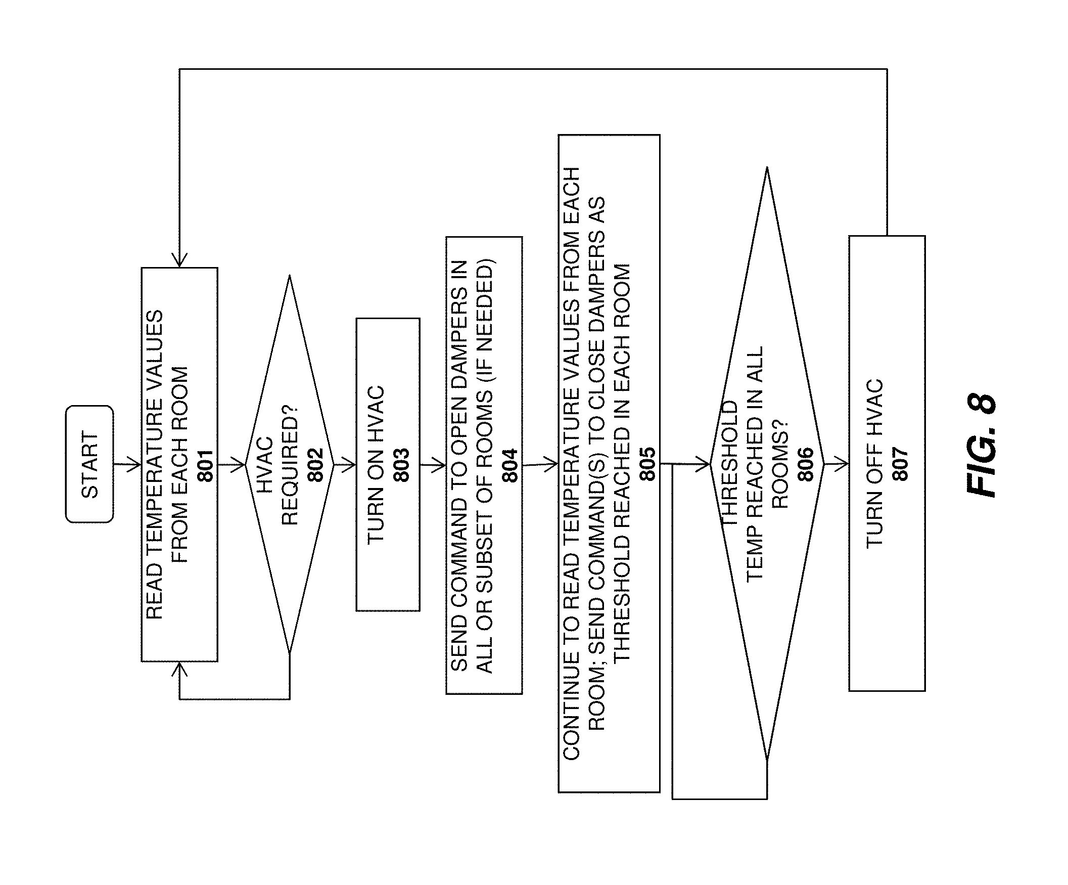
A method in accordance with one embodiment of the invention is illustrated in FIG. 8. The method may be implemented within the context of the system architectures described above, but is not limited to any particular system architecture.
At 801, temperatures are read from the temperature sensors in each room and at 802 a determination is made as to whether the HVAC system is required. For example, if the temperature in a particular room as dropped below or risen above a specified threshold, then the HVAC system may be turned on at 803. At 804, a command is sent to all or a subset of the smart registers to open their dampers. For example, if only a subset of rooms are showing a temperature above or below the desired threshold, then only the dampers for those rooms may need to be opened. Of course, in one embodiment, if the dampers are already opened in these rooms, then no command is required.
Once the HVAC system has been running for a period of time, the temperatures will rise (if heating is used) or fall (if air conditioning is used). At 805, the temperature values are collected from each room and commands are sent to close dampers of smart registers in those rooms where a specified temperature threshold has been reached. In one embodiment, the temperature threshold is an offset from the desired temperature. For example, if the user has indicated a desired temperature of 70 degrees F. then for heating, the temperature threshold may be set at 71 degrees F. As the dampers of each smart register are closed, the air pressure in the smart registers with dampers open will increase, thereby causing the heating/cooling to operate more efficiently. When the threshold temperature has been reached in all rooms, determined at 806, the HVAC system is turned off at 807 and the process returns to 801.
FIG. 9 illustrates an embodiment in which the decision to open/close dampers is made at each individual smart register. Like the method of FIG. 8, this method may be implemented within the context of the system architectures described above, but is not limited to any particular system architecture.
At 901 temperatures are read from the temperature sensors in each room and at 902 a determination is made as to whether the HVAC system is required. For example, if the temperature in a particular room as dropped below or risen above a specified threshold, then the HVAC system may be turned on at 903.
At 904, the current and desired temperatures are sent to the smart registers. In one embodiment, the temperatures are transmitted to the smart registers via the IoT hub or IoT thermostat. In an alternate embodiment, the current temperatures are provided directly from the temperature sensors to the smart registers. At 905, each smart register makes a decision to open/close its dampers in accordance with the desired temperature and measured current temperature. For example, if the desired temperature is 70 degrees F. and the current temperature in a room is 68 degrees F., then the smart register in that room will leave its dampers open (or open them if they are closed). As the temperature threshold is reached in each room (e.g., 71 degrees for heating), the smart register in that room will close its dampers, thereby increasing pressure in the remaining rooms and speeding the overall heating/cooling process. When the threshold temperature has been reached in all of the rooms, determined at 906, the HVAC system is turned off at 907.
Using the techniques described above will allow for significantly more efficient HVAC operation because the overall time for running the HVAC system will be decreased. This is in part due to the increased pressure in the rooms with dampers open and due to the fact that users will not set the temperature higher or lower than the desired temperatures given the insulation differences between each of the rooms in the user's home.
While the embodiments are discussed above within the context of an IoT system with an IoT hub and thermostat, the same underlying principles may be applied to a stand-alone smart register unit that fits in an existing duct and provides a mechanism for the user to select a desired temperature (e.g., using a simple dial or scroll wheel). In such a case, the smart register will read the current temperature via a temperature sensor and keep the dampers open until the desired temperature (or an offset from the desired temperature) is reached, without any interaction with the IoT hub or thermostat.
Embodiments for Improved Security
In one embodiment, the low power microcontroller 200 of each IoT device 101 and the low power logic/microcontroller 301 of the IoT hub 110 include a secure key store for storing encryption keys used by the embodiments described below (see, e.g., FIGS. 10-15 and associated text). Alternatively, the keys may be secured in a subscriber identify module (SIM) as discussed below.
FIG. 10 illustrates a high level architecture which uses public key infrastructure (PKI) techniques and/or symmetric key exchange/encryption techniques to encrypt communications between the IoT Service 120, the IoT hub 110 and the IoT devices 101-102.
Embodiments which use public/private key pairs will first be described, followed by embodiments which use symmetric key exchange/encryption techniques. In particular, in an embodiment which uses PKI, a unique public/private key pair is associated with each IoT device 101-102, each IoT hub 110 and the IoT service 120. In one embodiment, when a new IoT hub 110 is set up, its public key is provided to the IoT service 120 and when a new IoT device 101 is set up, it's public key is provided to both the IoT hub 110 and the IoT service 120. Various techniques for securely exchanging the public keys between devices are described below. In one embodiment, all public keys are signed by a master key known to all of the receiving devices (i.e., a form of certificate) so that any receiving device can verify the validity of the public keys by validating the signatures. Thus, these certificates would be exchanged rather than merely exchanging the raw public keys.
As illustrated, in one embodiment, each IoT device 101, 102 includes a secure key storage 1001, 1003, respectively, for security storing each device's private key. Security logic 1002, 1304 then utilizes the securely stored private keys to perform the encryption/decryption operations described herein. Similarly, the IoT hub 110 includes a secure storage 1011 for storing the IoT hub private key and the public keys of the IoT devices 101-102 and the IoT service 120; as well as security logic 1012 for using the keys to perform encryption/decryption operations. Finally, the IoT service 120 may include a secure storage 1021 for security storing its own private key, the public keys of various IoT devices and IoT hubs, and a security logic 1013 for using the keys to encrypt/decrypt communication with IoT hubs and devices. In one embodiment, when the IoT hub 110 receives a public key certificate from an IoT device it can verify it (e.g., by validating the signature using the master key as described above), and then extract the public key from within it and store that public key in it's secure key store 1011.
By way of example, in one embodiment, when the IoT service 120 needs to transmit a command or data to an IoT device 101 (e.g., a command to unlock a door, a request to read a sensor, data to be processed/displayed by the IoT device, etc) the security logic 1013 encrypts the data/command using the public key of the IoT device 101 to generate an encrypted IoT device packet. In one embodiment, it then encrypts the IoT device packet using the public key of the IoT hub 110 to generate an IoT hub packet and transmits the IoT hub packet to the IoT hub 110. In one embodiment, the service 120 signs the encrypted message with it's private key or the master key mentioned above so that the device 101 can verify it is receiving an unaltered message from a trusted source. The device 101 may then validate the signature using the public key corresponding to the private key and/or the master key. As mentioned above, symmetric key exchange/encryption techniques may be used instead of public/private key encryption. In these embodiments, rather than privately storing one key and providing a corresponding public key to other devices, the devices may each be provided with a copy of the same symmetric key to be used for encryption and to validate signatures. One example of a symmetric key algorithm is the Advanced Encryption Standard (AES), although the underlying principles of the invention are not limited to any type of specific symmetric keys.
Using a symmetric key implementation, each device 101 enters into a secure key exchange protocol to exchange a symmetric key with the IoT hub 110. A secure key provisioning protocol such as the Dynamic Symmetric Key Provisioning Protocol (DSKPP) may be used to exchange the keys over a secure communication channel (see, e.g., Request for Comments (RFC) 6063). However, the underlying principles of the invention are not limited to any particular key provisioning protocol.
Once the symmetric keys have been exchanged, they may be used by each device 101 and the IoT hub 110 to encrypt communications. Similarly, the IoT hub 110 and IoT service 120 may perform a secure symmetric key exchange and then use the exchanged symmetric keys to encrypt communications. In one embodiment a new symmetric key is exchanged periodically between the devices 101 and the hub 110 and between the hub 110 and the IoT service 120. In one embodiment, a new symmetric key is exchanged with each new communication session between the devices 101, the hub 110, and the service 120 (e.g., a new key is generated and securely exchanged for each communication session). In one embodiment, if the security module 1012 in the IoT hub is trusted, the service 120 could negotiate a session key with the hub security module 1312 and then the security module 1012 would negotiate a session key with each device 120. Messages from the service 120 would then be decrypted and verified in the hub security module 1012 before being re-encrypted for transmission to the device 101.
In one embodiment, to prevent a compromise on the hub security module 1012 a one-time (permanent) installation key may be negotiated between the device 101 and service 120 at installation time. When sending a message to a device 101 the service 120 could first encrypt/MAC with this device installation key, then encrypt/MAC that with the hub's session key. The hub 110 would then verify and extract the encrypted device blob and send that to the device.
In one embodiment of the invention, a counter mechanism is implemented to prevent replay attacks. For example, each successive communication from the device 101 to the hub 110 (or vice versa) may be assigned a continually increasing counter value. Both the hub 110 and device 101 will track this value and verify that the value is correct in each successive communication between the devices. The same techniques may be implemented between the hub 110 and the service 120. Using a counter in this manner would make it more difficult to spoof the communication between each of the devices (because the counter value would be incorrect). However, even without this a shared installation key between the service and device would prevent network (hub) wide attacks to all devices.
In one embodiment, when using public/private key encryption, the IoT hub 110 uses its private key to decrypt the IoT hub packet and generate the encrypted IoT device packet, which it transmits to the associated IoT device 101. The IoT device 101 then uses its private key to decrypt the IoT device packet to generate the command/data originated from the IoT service 120. It may then process the data and/or execute the command. Using symmetric encryption, each device would encrypt and decrypt with the shared symmetric key. If either case, each transmitting device may also sign the message with it's private key so that the receiving device can verify it's authenticity.
A different set of keys may be used to encrypt communication from the IoT device 101 to the IoT hub 110 and to the IoT service 120. For example, using a public/private key arrangement, in one embodiment, the security logic 1002 on the IoT device 101 uses the public key of the IoT hub 110 to encrypt data packets sent to the IoT hub 110. The security logic 1012 on the IoT hub 110 may then decrypt the data packets using the IoT hub's private key. Similarly, the security logic 1002 on the IoT device 101 and/or the security logic 1012 on the IoT hub 110 may encrypt data packets sent to the IoT service 120 using the public key of the IoT service 120 (which may then be decrypted by the security logic 1013 on the IoT service 120 using the service's private key). Using symmetric keys, the device 101 and hub 110 may share a symmetric key while the hub and service 120 may share a different symmetric key.
While certain specific details are set forth above in the description above, it should be noted that the underlying principles of the invention may be implemented using various different encryption techniques. For example, while some embodiments discussed above use asymmetric public/private key pairs, an alternate embodiment may use symmetric keys securely exchanged between the various IoT devices 101-102, IoT hubs 110, and the IoT service 120. Moreover, in some embodiments, the data/command itself is not encrypted, but a key is used to generate a signature over the data/command (or other data structure). The recipient may then use its key to validate the signature.
As illustrated in FIG. 11, in one embodiment, the secure key storage on each IoT device 101 is implemented using a programmable subscriber identity module (SIM) 1101. In this embodiment, the IoT device 101 may initially be provided to the end user with an un-programmed SIM card 1101 seated within a SIM interface 1100 on the IoT device 101. In order to program the SIM with a set of one or more encryption keys, the user takes the programmable SIM card 1101 out of the SIM interface 500 and inserts it into a SIM programming interface 1102 on the IoT hub 110. Programming logic 1125 on the IoT hub then securely programs the SIM card 1101 to register/pair the IoT device 101 with the IoT hub 110 and IoT service 120. In one embodiment, a public/private key pair may be randomly generated by the programming logic 1125 and the public key of the pair may then be stored in the IoT hub's secure storage device 411 while the private key may be stored within the programmable SIM 1101. In addition, the programming logic 525 may store the public keys of the IoT hub 110, the IoT service 120, and/or any other IoT devices 101 on the SIM card 1401 (to be used by the security logic 1302 on the IoT device 101 to encrypt outgoing data). Once the SIM 1101 is programmed, the new IoT device 101 may be provisioned with the IoT Service 120 using the SIM as a secure identifier (e.g., using existing techniques for registering a device using a SIM). Following provisioning, both the IoT hub 110 and the IoT service 120 will securely store a copy of the IoT device's public key to be used when encrypting communication with the IoT device 101.
The techniques described above with respect to FIG. 11 provide enormous flexibility when providing new IoT devices to end users. Rather than requiring a user to directly register each SIM with a particular service provider upon sale/purchase (as is currently done), the SIM may be programmed directly by the end user via the IoT hub 110 and the results of the programming may be securely communicated to the IoT service 120. Consequently, new IoT devices 101 may be sold to end users from online or local retailers and later securely provisioned with the IoT service 120.
While the registration and encryption techniques are described above within the specific context of a SIM (Subscriber Identity Module), the underlying principles of the invention are not limited to a "SIM" device. Rather, the underlying principles of the invention may be implemented using any type of device having secure storage for storing a set of encryption keys. Moreover, while the embodiments above include a removable SIM device, in one embodiment, the SIM device is not removable but the IoT device itself may be inserted within the programming interface 1102 of the IoT hub 110.
In one embodiment, rather than requiring the user to program the SIM (or other device), the SIM is pre-programmed into the IoT device 101, prior to distribution to the end user. In this embodiment, when the user sets up the IoT device 101, various techniques described herein may be used to securely exchange encryption keys between the IoT hub 110/IoT service 120 and the new IoT device 101.
For example, as illustrated in FIG. 12A each IoT device 101 or SIM 401 may be packaged with a barcode or QR code 1501 uniquely identifying the IoT device 101 and/or SIM 1001. In one embodiment, the barcode or QR code 1201 comprises an encoded representation of the public key for the IoT device 101 or SIM 1001. Alternatively, the barcode or QR code 1201 may be used by the IoT hub 110 and/or IoT service 120 to identify or generate the public key (e.g., used as a pointer to the public key which is already stored in secure storage). The barcode or QR code 601 may be printed on a separate card (as shown in FIG. 12A) or may be printed directly on the IoT device itself. Regardless of where the barcode is printed, in one embodiment, the IoT hub 110 is equipped with a barcode reader 206 for reading the barcode and providing the resulting data to the security logic 1012 on the IoT hub 110 and/or the security logic 1013 on the IoT service 120. The security logic 1012 on the IoT hub 110 may then store the public key for the IoT device within its secure key storage 1011 and the security logic 1013 on the IoT service 120 may store the public key within its secure storage 1021 (to be used for subsequent encrypted communication).
In one embodiment, the data contained in the barcode or QR code 1201 may also be captured via a user device 135 (e.g., such as an iPhone or Android device) with an installed IoT app or browser-based applet designed by the IoT service provider. Once captured, the barcode data may be securely communicated to the IoT service 120 over a secure connection (e.g., such as a secure sockets layer (SSL) connection). The barcode data may also be provided from the client device 135 to the IoT hub 110 over a secure local connection (e.g., over a local WiFi or Bluetooth LE connection).
The security logic 1002 on the IoT device 101 and the security logic 1012 on the IoT hub 110 may be implemented using hardware, software, firmware or any combination thereof. For example, in one embodiment, the security logic 1002, 1012 is implemented within the chips used for establishing the local communication channel 130 between the IoT device 101 and the IoT hub 110 (e.g., the Bluetooth LE chip if the local channel 130 is Bluetooth LE). Regardless of the specific location of the security logic 1002, 1012, in one embodiment, the security logic 1002, 1012 is designed to establish a secure execution environment for executing certain types of program code. This may be implemented, for example, by using TrustZone technology (available on some ARM processors) and/or Trusted Execution Technology (designed by Intel). Of course, the underlying principles of the invention are not limited to any particular type of secure execution technology.
In one embodiment, the barcode or QR code 1501 may be used to pair each IoT device 101 with the IoT hub 110. For example, rather than using the standard wireless pairing process currently used to pair Bluetooth LE devices, a pairing code embedded within the barcode or QR code 1501 may be provided to the IoT hub 110 to pair the IoT hub with the corresponding IoT device.
FIG. 12B illustrates one embodiment in which the barcode reader 206 on the IoT hub 110 captures the barcode/QR code 1201 associated with the IoT device 101. As mentioned, the barcode/QR code 1201 may be printed directly on the IoT device 101 or may be printed on a separate card provided with the IoT device 101. In either case, the barcode reader 206 reads the pairing code from the barcode/QR code 1201 and provides the pairing code to the local communication module 1280. In one embodiment, the local communication module 1280 is a Bluetooth LE chip and associated software, although the underlying principles of the invention are not limited to any particular protocol standard. Once the pairing code is received, it is stored in a secure storage containing pairing data 1285 and the IoT device 101 and IoT hub 110 are automatically paired. Each time the IoT hub is paired with a new IoT device in this manner, the pairing data for that pairing is stored within the secure storage 685. In one embodiment, once the local communication module 1280 of the IoT hub 110 receives the pairing code, it may use the code as a key to encrypt communications over the local wireless channel with the IoT device 101.
Similarly, on the IoT device 101 side, the local communication module 1590 stores pairing data within a local secure storage device 1595 indicating the pairing with the IoT hub. The pairing data 1295 may include the pre-programmed pairing code identified in the barcode/QR code 1201. The pairing data 1295 may also include pairing data received from the local communication module 1280 on the IoT hub 110 required for establishing a secure local communication channel (e.g., an additional key to encrypt communication with the IoT hub 110).
Thus, the barcode/QR code 1201 may be used to perform local pairing in a far more secure manner than current wireless pairing protocols because the pairing code is not transmitted over the air. In addition, in one embodiment, the same barcode/QR code 1201 used for pairing may be used to identify encryption keys to build a secure connection from the IoT device 101 to the IoT hub 110 and from the IoT hub 110 to the IoT service 120.
A method for programming a SIM card in accordance with one embodiment of the invention is illustrated in FIG. 13. The method may be implemented within the system architecture described above, but is not limited to any particular system architecture.
At 1301, a user receives a new IoT device with a blank SIM card and, at 1602, the user inserts the blank SIM card into an IoT hub. At 1303, the user programs the blank SIM card with a set of one or more encryption keys. For example, as mentioned above, in one embodiment, the IoT hub may randomly generate a public/private key pair and store the private key on the SIM card and the public key in its local secure storage. In addition, at 1304, at least the public key is transmitted to the IoT service so that it may be used to identify the IoT device and establish encrypted communication with the IoT device. As mentioned above, in one embodiment, a programmable device other than a "SIM" card may be used to perform the same functions as the SIM card in the method shown in FIG. 13.
A method for integrating a new IoT device into a network is illustrated in FIG. 14. The method may be implemented within the system architecture described above, but is not limited to any particular system architecture.
At 1401, a user receives a new IoT device to which an encryption key has been pre-assigned. At 1402, the key is securely provided to the IoT hub. As mentioned above, in one embodiment, this involves reading a barcode associated with the IoT device to identify the public key of a public/private key pair assigned to the device. The barcode may be read directly by the IoT hub or captured via a mobile device via an app or browser. In an alternate embodiment, a secure communication channel such as a Bluetooth LE channel, a near field communication (NFC) channel or a secure WiFi channel may be established between the IoT device and the IoT hub to exchange the key. Regardless of how the key is transmitted, once received, it is stored in the secure keystore of the IoT hub device. As mentioned above, various secure execution technologies may be used on the IoT hub to store and protect the key such as Secure Enclaves, Trusted Execution Technology (TXT), and/or Trustzone. In addition, at 803, the key is securely transmitted to the IoT service which stores the key in its own secure keystore. It may then use the key to encrypt communication with the IoT device. One again, the exchange may be implemented using a certificate/signed key. Within the hub 110 it is particularly important to prevent modification/addition/removal of the stored keys.
A method for securely communicating commands/data to an IoT device using public/private keys is illustrated in FIG. 15. The method may be implemented within the system architecture described above, but is not limited to any particular system architecture.
At 1501, the IoT service encrypts the data/commands using the IoT device public key to create an IoT device packet. It then encrypts the IoT device packet using IoT hub's public key to create the IoT hub packet (e.g., creating an IoT hub wrapper around the IoT device packet). At 1502, the IoT service transmits the IoT hub packet to the IoT hub. At 1503, the IoT hub decrypts the IoT hub packet using the IoT hub's private key to generate the IoT device packet. At 1504 it then transmits the IoT device packet to the IoT device which, at 1505, decrypts the IoT device packet using the IoT device private key to generate the data/commands. At 1506, the IoT device processes the data/commands.
In an embodiment which uses symmetric keys, a symmetric key exchange may be negotiated between each of the devices (e.g., each device and the hub and between the hub and the service). Once the key exchange is complete, each transmitting device encrypts and/or signs each transmission using the symmetric key before transmitting data to the receiving device.
Embodiments of the invention may include various steps, which have been described above. The steps may be embodied in machine-executable instructions which may be used to cause a general-purpose or special-purpose processor to perform the steps. Alternatively, these steps may be performed by specific hardware components that contain hardwired logic for performing the steps, or by any combination of programmed computer components and custom hardware components.
As described herein, instructions may refer to specific configurations of hardware such as application specific integrated circuits (ASICs) configured to perform certain operations or having a predetermined functionality or software instructions stored in memory embodied in a non-transitory computer readable medium. Thus, the techniques shown in the figures can be implemented using code and data stored and executed on one or more electronic devices (e.g., an end station, a network element, etc.). Such electronic devices store and communicate (internally and/or with other electronic devices over a network) code and data using computer machine-readable media, such as non-transitory computer machine-readable storage media (e.g., magnetic disks; optical disks; random access memory; read only memory; flash memory devices; phase-change memory) and transitory computer machine-readable communication media (e.g., electrical, optical, acoustical or other form of propagated signals--such as carrier waves, infrared signals, digital signals, etc.). In addition, such electronic devices typically include a set of one or more processors coupled to one or more other components, such as one or more storage devices (non-transitory machine-readable storage media), user input/output devices (e.g., a keyboard, a touchscreen, and/or a display), and network connections. The coupling of the set of processors and other components is typically through one or more busses and bridges (also termed as bus controllers). The storage device and signals carrying the network traffic respectively represent one or more machine-readable storage media and machine-readable communication media. Thus, the storage device of a given electronic device typically stores code and/or data for execution on the set of one or more processors of that electronic device. Of course, one or more parts of an embodiment of the invention may be implemented using different combinations of software, firmware, and/or hardware.
Throughout this detailed description, for the purposes of explanation, numerous specific details were set forth in order to provide a thorough understanding of the present invention. It will be apparent, however, to one skilled in the art that the invention may be practiced without some of these specific details. In certain instances, well known structures and functions were not described in elaborate detail in order to avoid obscuring the subject matter of the present invention. Accordingly, the scope and spirit of the invention should be judged in terms of the claims which follow.
* * * * *
D00000
D00001
D00002
D00003
D00004
D00005
D00006
D00007
D00008
D00009
D00010
D00011
D00012

D00013
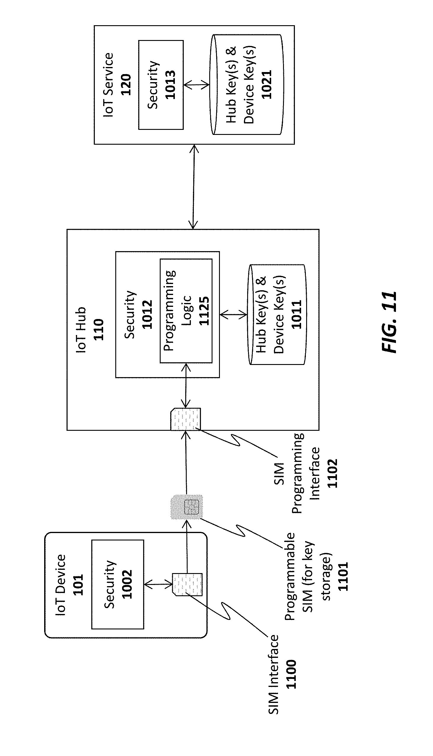
D00014

D00015
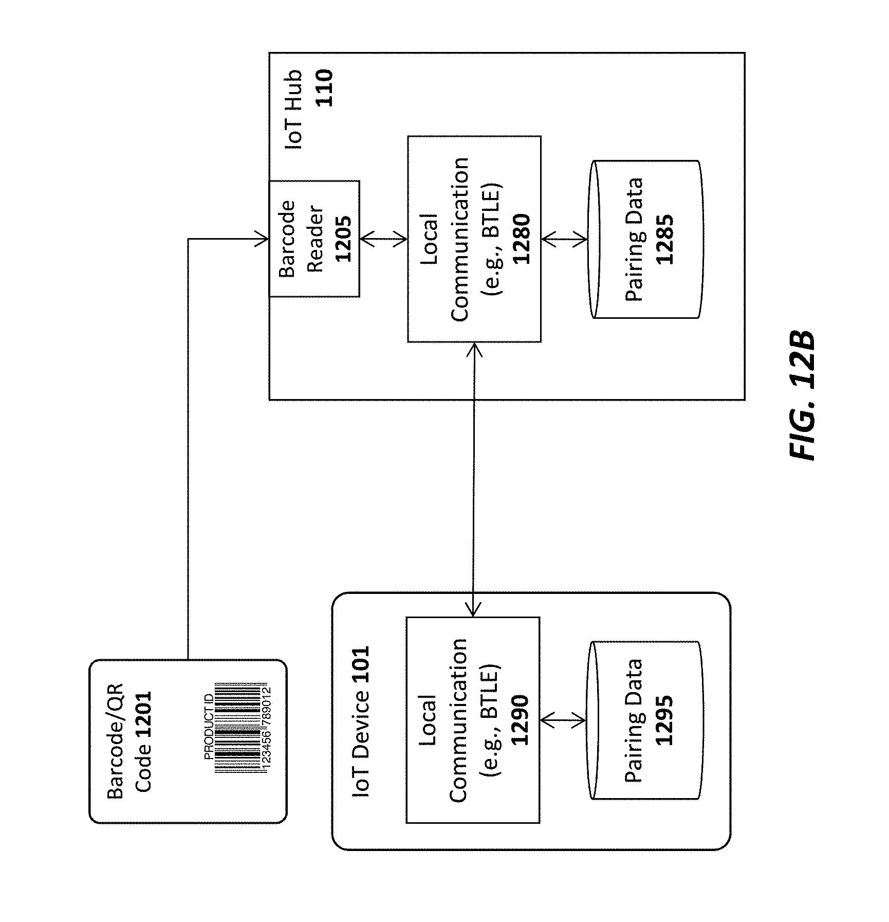
D00016

D00017

D00018

XML
uspto.report is an independent third-party trademark research tool that is not affiliated, endorsed, or sponsored by the United States Patent and Trademark Office (USPTO) or any other governmental organization. The information provided by uspto.report is based on publicly available data at the time of writing and is intended for informational purposes only.
While we strive to provide accurate and up-to-date information, we do not guarantee the accuracy, completeness, reliability, or suitability of the information displayed on this site. The use of this site is at your own risk. Any reliance you place on such information is therefore strictly at your own risk.
All official trademark data, including owner information, should be verified by visiting the official USPTO website at www.uspto.gov. This site is not intended to replace professional legal advice and should not be used as a substitute for consulting with a legal professional who is knowledgeable about trademark law.